

Page 1

PremierWave XN
Intelligent Gateway User Guide
Part Number 900-606
Revision F October 2016
Page 2

Intellectual Property
© 2016 Lantronix, Inc. All rights reserved. No part of the contents of this publication may be
transmitted or reproduced in any form or by any means without the written permission of Lantronix.
Lantronix and PremierWave are registered trademarks of Lantronix, Inc. in the United States and
other countries. DeviceInstaller is a trademark of Lantronix, Inc.
Patented: patents.lantronix.com
Windows and Internet Explorer are registered trademarks of Microsoft Corporation. Mozilla and
Firefox are registered trademarks of the Mozilla Foundation. Chrome is a trademark of Google Inc.
Opera is a trademark of Opera Software ASA Corporation Norway. Safari is a registered
trademark of Apple Inc. Wi-Fi is a trademark of Wi-Fi Alliance Corporation. Python is a trademark
of Python Software Foundation. All other trademarks and trade names are the property of their
respective holders.
Open Source Software
Some applications are Open Source software licensed under the Berkeley Software Distribution
(BSD) license, the GNU General Public License (GPL) as published by the Free Software
Foundation (FSF), or the Python Software Foundation (PFS) License Agreement for Python 2.7.3
(Python License). Lantronix grants you no right to receive source code to the Open Source
software; however, in some cases, rights and access to source code for certain Open Source
software may be available directly from Lantronix’ licensors. Your use of each Open Source
component or software is subject to the terms of the applicable license. The BSD license is
available at http://opensource.org/licenses. The GNU General Public License is available at
http://www.gnu.org/licenses/
Docs/license.html. Your use of each Open Source component or software is subject to the terms
of the applicable license.
OPEN SOURCE SOFTWARE IS DISTRIBUTED WITHOUT ANY WARRANTY, INCLUDING ANY
IMPLIED WARRANTY OF MERCHANTABILITY OR FITNESS FOR A PARTICULAR PURPOSE.
SEE THE APPLICABLE LICENSE AGREEMENT FOR ADDITIONAL INFORMATION.
; additional patents pending.
. The Python License is available at http://cmpt165.csil.sfu.ca/Python-
Warranty
For details on the Lantronix warranty policy, please go to our web site at
www.lantronix.com/support/warranty
.
Contacts
Lantronix, Inc.
7535 Irvine Center Drive
Suite 100
Irvine, CA 92618, USA
Toll Free: 800-526-8766
Phone: 949-453-3990
Fax: 949-453-3995
Technical Support
Online: www.lantronix.com/support
PremierWave® XN Intelligent Gateway User Guide 2
Page 3

Sales Offices
For a current list of our domestic and international sales offices, go to the Lantronix web site at
www.lantronix.com/about/contact
Disclaimer
All information contained herein is provided “AS IS.” Lantronix undertakes no obligation to
update the information in this publication. Lantronix does not make, and specifically disclaims,
all warranties of any kind (express, implied or otherwise) regarding title, non-infringement, fitness,
quality, accuracy, completeness, usefulness, suitability or performance of the information provided
herein. Lantronix shall have no liability whatsoever to any user for any damages, losses and
causes of action (whether in contract or in tort or otherwise) in connection with the user’s access or
usage of any of the information or content contained herein. The information and specifications
contained in this document are subject to change without notice.
Revision History
Date Rev. Comments
February 2012 A Initial document for firmware release 7.3.0.0.
December 2012 B Updated pinout and LED information.
August 2013 C Updated dimension drawing and directions for uploading firmware.
October 2014 D Updated document to firmware release 7.9.0.0.
September 2015 E Updated signal LED descriptions, email subject default behavior, and
October 2016 F Updated document to firmware release 8.0.0.0R19. Changes include:
.
updated compliance information.
Added Modbus, IPv6, and Initial Send content.
Updated Flash and SNMP information.
Removed Query Port content.
PremierWave® XN Intelligent Gateway User Guide 3
Page 4

Table of Contents
Intellectual Property ________________________________________________________2
Open Source Software ______________________________________________________2
Warranty _________________________________________________________________2
Contacts _________________________________________________________________2
Disclaimer ________________________________________________________________3
Revision History ___________________________________________________________3
List of Figures ____________________________________________________________11
List of Tables ____________________________________________________________12
1: Using This Guide 15
Purpose and Audience _____________________________________________________15
Summary of Chapters ______________________________________________________15
Additional Documentation ___________________________________________________16
2: Introduction 17
Key Features _____________________________________________________________17
Applications ______________________________________________________________17
Protocol Support _________________________________________________________18
Troubleshooting Capabilities _________________________________________________18
Configuration Methods _____________________________________________________18
Addresses and Port Numbers ________________________________________________19
Hardware Address _____________________________________________________19
IP Address ___________________________________________________________19
Port Numbers _________________________________________________________19
Product Information Label ___________________________________________________19
3: Installation of the PremierWave XN Device 21
Package Contents _________________________________________________________21
User-Supplied Items _______________________________________________________21
Hardware Components _____________________________________________________22
Front/Top Panel _______________________________________________________22
Back Panel ___________________________________________________________26
Wi-Fi Protected Setup (WPS) _____________________________________________27
To Start WPS _________________________________________________________27
To Cancel WPS _______________________________________________________27
To Show WPS Status ___________________________________________________27
Installing the PremierWave XN Device _________________________________________28
PremierWave® XN Intelligent Gateway User Guide 4
Page 5

4: Device Discovery and Quick Setup 30
Accessing the PremierWave XN Device Using UPnP _____________________________30
Accessing the PremierWave XN Device Using DeviceInstaller ______________________31
Device Detail Summary _____________________________________________________31
5: Configuration Using Web Manager 33
Accessing Web Manager ___________________________________________________33
Device Status Page ________________________________________________________34
Web Manager Components _________________________________________________35
Navigating Web Manager ___________________________________________________36
6: Network Settings 38
Network 1 Status __________________________________________________________38
Network 1 (eth0) Interface Settings ____________________________________________38
To Configure Network 1 Interface Settings ___________________________________40
Network 1 (eth0) Link Settings _______________________________________________41
To Configure Network 1 Link Settings ______________________________________41
Network 1 (eth0) QoS ______________________________________________________41
To Configure Network 1 QoS Settings ______________________________________42
Network 1 (eth0) Failover ___________________________________________________43
To Configure Network 1 Failover Settings ___________________________________43
Network 2 Status __________________________________________________________43
Network 2 (wlan0) Interface Settings __________________________________________44
To Configure Network 2 Interface Settings ___________________________________45
SmartRoam __________________________________________________________45
Network 2 (wlan0) Link Settings ______________________________________________46
To Configure Network 2 Link Settings ______________________________________46
Network 2 (wlan0) QoS _____________________________________________________47
To Configure Network 2 QoS Settings ______________________________________48
WLAN Link Status and Scan Commands ____________________________________48
To View WLAN Link Scan and Status Information _____________________________50
Network 2 (wlan0) Failover __________________________________________________50
To Configure Network 2 Failover Settings ___________________________________51
WLAN Profiles ____________________________________________________________51
To Configure WLAN Profiles _____________________________________________51
To Configure WLAN Profile Basic Settings ___________________________________52
To Configure WLAN Profile Advanced Settings _______________________________53
WLAN Profile Security Settings ___________________________________________54
To Configure WLAN Profile Security Settings ________________________________55
WLAN Profile WEP Settings ______________________________________________56
To Configure WLAN Profile WEP Settings ___________________________________57
WLAN Profile WPA and WPA2/IEEE802.11i Settings __________________________57
PremierWave® XN Intelligent Gateway User Guide 5
Page 6

To Configure WLAN Profile WPA and WPA/IEEE802.11i Settings ________________ 59
WLAN Quick Connect ______________________________________________________60
To Configure WLAN Quick Connect ________________________________________60
Gateway ________________________________________________________________61
Status _______________________________________________________________61
WAN ________________________________________________________________61
WAN MAC Address Filters _______________________________________________62
To Configure Gateway WAN Settings ______________________________________62
Port Forwarding _______________________________________________________62
To Configure Gateway Port Forwarding Settings ______________________________63
Static Routes _________________________________________________________63
To Configure Gateway Static Route Settings _________________________________64
DHCP Server _________________________________________________________64
To Configure Gateway DHCP Server Settings ________________________________ 65
Routing Protocols ______________________________________________________65
To Configure Gateway Routing Protocol Settings _____________________________66
Virtual IP _____________________________________________________________66
To Configure Gateway Virtual IP __________________________________________66
DDNS __________________________________________________________________67
To Configure Gateway WAN Settings ______________________________________67
VPN ____________________________________________________________________67
To Configure VPN Settings ______________________________________________69
GRE Settings ____________________________________________________________70
To Configure Tunnel Serial Settings ________________________________________70
7: Action Settings 71
Alarms and Reports _______________________________________________________71
Actions _________________________________________________________________71
To Configure Action Settings _____________________________________________72
Python __________________________________________________________________73
IDE _________________________________________________________________73
Applications ______________________________________________________________74
To Configure Application Settings _________________________________________75
8: Line and Tunnel Settings 76
Line Statistics ____________________________________________________________76
Line Settings _____________________________________________________________76
To Configure Line Settings _______________________________________________76
To Configure Line Command Mode ________________________________________79
Tunnel Statistics __________________________________________________________79
To View Tunnel Statistics ________________________________________________79
Tunnel Settings ___________________________________________________________80
Serial Settings ________________________________________________________80
PremierWave® XN Intelligent Gateway User Guide 6
Page 7

To Configure Tunnel Serial Settings ________________________________________80
Packing Mode _________________________________________________________81
To Configure Tunnel Packing Mode Settings _________________________________81
Accept Mode __________________________________________________________82
To Configure Tunnel Accept Mode Settings __________________________________84
Connect Mode ________________________________________________________84
Connecting Multiple Hosts _______________________________________________87
Host List Promotion ____________________________________________________87
Disconnect Mode ______________________________________________________87
To Configure Tunnel Disconnect Mode Settings ______________________________88
Modem Emulation ______________________________________________________88
To Configure Tunnel Modem Emulation Settings ______________________________89
9: Terminal and Host Settings 90
Terminal Settings _________________________________________________________90
To Configure the Terminal Network Connection _______________________________91
To Configure the Terminal Line Connection __________________________________91
Host Configuration ________________________________________________________91
To Configure Host Settings ______________________________________________92
10: Maintenance and Diagnostics Settings 93
Filesystem Settings ________________________________________________________93
Statistics _____________________________________________________________93
To View Statistics ______________________________________________________93
File Display ___________________________________________________________93
To Display Files _______________________________________________________94
File Modification _______________________________________________________94
File Transfer __________________________________________________________94
To Transfer or Modify Filesystem Files ______________________________________95
Protocol Stack Settings _____________________________________________________95
IP Settings ___________________________________________________________95
To Configure IP Protocol Stack Settings ____________________________________96
ICMP Settings _________________________________________________________96
To Configure ICMP Protocol Stack Settings __________________________________96
ARP Settings _________________________________________________________96
To Configure ARP Network Stack Settings __________________________________97
Diagnostics ______________________________________________________________97
Hardware ____________________________________________________________97
To View Hardware Information ____________________________________________97
IP Sockets ___________________________________________________________97
To View the List of IP Sockets ____________________________________________97
Ping ________________________________________________________________98
To Ping a Remote Host _________________________________________________98
PremierWave® XN Intelligent Gateway User Guide 7
Page 8

Traceroute ___________________________________________________________98
To Perform a Traceroute ________________________________________________99
Log _________________________________________________________________99
To Configure the Diagnostic Log Output ____________________________________99
Memory _____________________________________________________________100
To View Memory Usage ________________________________________________100
Processes ___________________________________________________________100
To View Process Information ____________________________________________100
Threads ____________________________________________________________100
To View Thread Information _____________________________________________100
Clock __________________________________________________________________101
To Specify Clock Setting Method _________________________________________101
System Settings _________________________________________________________102
To Reboot or Restore Factory Defaults ____________________________________102
11: Management Interface Settings 103
Command Line Interface Settings ____________________________________________103
Basic CLI Settings ____________________________________________________103
To View and Configure Basic CLI Settings __________________________________103
Telnet Settings _______________________________________________________104
To Configure Telnet CLI Settings _________________________________________104
SSH CLI Settings _____________________________________________________104
To Configure SSH Settings _____________________________________________105
XML Settings ____________________________________________________________105
XML: Export Configuration ______________________________________________105
To Export Configuration in XML Format ____________________________________106
XML: Export Status ____________________________________________________106
To Export in XML Format _______________________________________________106
XML: Import Configuration ______________________________________________107
To Import Configuration in XML Format ____________________________________108
12: Bridging 109
Bridging Configuration _____________________________________________________109
To configure and enable bridging: ________________________________________109
Bridging Operation _______________________________________________________110
Bridge Configuration ______________________________________________________110
To View or Configure Bridge Settings _____________________________________110
13: Security Settings 112
Public Key Infrastructure ___________________________________________________112
TLS (SSL) ______________________________________________________________112
Digital Certificates ________________________________________________________113
PremierWave® XN Intelligent Gateway User Guide 8
Page 9

Trusted Authorities _______________________________________________________113
Obtaining Certificates _____________________________________________________113
Self-Signed Certificates ____________________________________________________113
Certificate Formats _______________________________________________________113
OpenSSL _______________________________________________________________114
Steel Belted RADIUS _____________________________________________________114
Free RADIUS ___________________________________________________________114
SSH Settings ____________________________________________________________115
SSH Server Host Keys _________________________________________________115
SSH Client Known Hosts _______________________________________________116
SSH Server Authorized Users ___________________________________________116
SSH Client Users _____________________________________________________ 117
To Configure SSH Settings _____________________________________________118
SSL Settings ____________________________________________________________118
Certificate and Key Generation __________________________________________118
To Create a New Credential _____________________________________________119
Certificate Upload Settings ______________________________________________120
To Configure an Existing SSL Credential ___________________________________120
Trusted Authorities ____________________________________________________121
14: Modbus 122
Serial Transmission Mode __________________________________________________122
Modbus Statistics ________________________________________________________123
To View Modbus Statistics ____________________________________________123
Modbus Configuration _____________________________________________________123
To View and Configure the Modbus Server: ______________________________123
15: Updating Firmware 124
Obtaining Firmware _______________________________________________________124
Loading New Firmware through Web Manager _________________________________124
Loading New Firmware through FTP _________________________________________126
16: Network Services 127
DNS Settings ____________________________________________________________127
To View or Configure DNS Settings: ______________________________________127
FTP Settings ____________________________________________________________128
To Configure FTP Settings ______________________________________________128
Syslog Settings __________________________________________________________128
To View or Configure Syslog Settings _____________________________________129
HTTP Settings ___________________________________________________________129
To Configure HTTP Settings ____________________________________________130
To Configure HTTP Authentication ________________________________________131
PremierWave® XN Intelligent Gateway User Guide 9
Page 10

RSS Settings ____________________________________________________________131
To Configure RSS Settings _____________________________________________132
SNMP Settings __________________________________________________________132
To Configure SNMP Settings ____________________________________________133
Discovery ______________________________________________________________133
To Configure Discovery ________________________________________________133
SMTP Settings __________________________________________________________134
To Configure SMTP Settings ____________________________________________134
Email Settings ___________________________________________________________134
To View, Configure and Send Email _______________________________________135
17: Branding the PremierWave XN Device 136
Web Manager Customization _______________________________________________136
Short and Long Name Customization _________________________________________137
To Customize Short or Long Names ______________________________________137
Appendix A: Lantronix Technical Support 138
Appendix B: Binary to Hexadecimal Conversions 139
Converting Binary to Hexadecimal ___________________________________________139
Conversion Table _____________________________________________________139
Scientific Calculator ___________________________________________________139
Appendix C: Compliance 141
PremierWave® XN Intelligent Gateway User Guide 10
Page 11

List of Figures
Figure 2-1 PremierWave XN Unit Product Label ________________________________________20
Figure 3-1 PremierWave XN Unit ____________________________________________________22
Figure 3-5 PremierWave XN Male DB9 DTE Serial Ports _________________________________24
Figure 3-6 PremierWave XN Pinout Configuration for RS-232______________________________24
Figure 3-7 PremierWave XN Pinout Configuration for Full Duplex RS-422/485 (4-wire) __________24
Figure 3-8 PremierWave XN Pinout Configuration for Half Duplex RS-422/485 (2-wire) __________24
Figure 3-14 PremierWave XN Bottom/Back Panel View___________________________________26
Figure 3-15 PremierWave XN WPS Button ____________________________________________27
Figure 3-16 PremierWave XN Unit Dimensions in Inches (in) and Centimeters (cm)_____________29
Figure 5-1 Device Status Page ______________________________________________________34
Figure 5-2 Components of the Web Manager Page ______________________________________35
Figure 15-1 Uploading New Firmware _______________________________________________125
PremierWave® XN Intelligent Gateway User Guide 11
Page 12

List of Tables
Table 3-2 PremierWave XN LEDs and Descriptions_____________________________________ 22
Table 3-3 Fault Conditions Indicated by Blink Patterns __________________________________ 23
Table 3-4 WPS Status Indicator ____________________________________________________ 23
Table 3-9 Left Ethernet LED _______________________________________________________ 25
Table 3-10 Right Ethernet LED_____________________________________________________ 25
Table 3-11 WLAN Signal Strength Indicator at 2.4 GHz__________________________________ 25
Table 3-12 WLAN Signal Strength Indicator for 5 GHz___________________________________ 25
Table 3-13 WPS Status Indicator ___________________________________________________ 26
Table 5-3 Web Manager Pages ____________________________________________________ 36
Table 6-1 Network Interface Settings ________________________________________________ 38
Table 6-2 Network 1 (eth0) Link Settings _____________________________________________ 41
Table 6-3 Network 1 (eth0) QoS Settings _____________________________________________ 42
Table 6-4 Network 1 (eth0) Failover Settings __________________________________________ 43
Table 6-5 Network 2 (wlan0) Interface Settings ________________________________________ 44
Table 6-6 Network 2 (wlan0) Link Settings ____________________________________________ 46
Table 6-7 Network 2 (wlan0) QoS Settings____________________________________________ 47
Table 6-8 Adding or Deleting Network 2 (wlan0) QoS Settings ____________________________ 47
Table 6-9 Network 2 Link Scan_____________________________________________________ 48
Table 6-10 Network 2 Link Scan Results on Web Manager _______________________________ 49
Table 6-11 Network 2 Link Status___________________________________________________ 49
Table 6-12 Network 2 (wlan0) Failover Settings ________________________________________ 50
Table 6-13 Creating, Deleting or Enabling WLAN Profiles ________________________________ 52
Table 6-14 WLAN Profile Basic Settings______________________________________________ 52
Table 6-15 WLAN Profile Advanced Settings __________________________________________ 53
Table 6-16 WLAN Profile Security Settings ___________________________________________ 54
Table 6-17 Additional WEP Settings for WLAN Profile. __________________________________ 56
Table 6-18 WLAN Profile WPA and WPA2/IEEE802.11i Settings __________________________ 57
Table 6-19 WLAN Quick Connect___________________________________________________ 60
Table 6-20 WAN Configuration _____________________________________________________ 61
Table 6-21 Adding a New MAC Address Filters ________________________________________ 62
Table 6-22 Port Forwarding Rules List _______________________________________________ 62
Table 6-23 Adding a New Port Forwarding Rule________________________________________ 63
Table 6-24 Static Route Setting Routes ______________________________________________ 63
Table 6-25 Adding a New Static Route _______________________________________________ 64
Table 6-26 DHCP Settings ________________________________________________________ 64
PremierWave® XN Intelligent Gateway User Guide 12
Page 13

Table 6-27 Routing Protocol Settings ________________________________________________ 65
Table 6-28 Virtual IP Settings ______________________________________________________ 66
Table 6-29 DDNS Configuration ____________________________________________________ 67
Table 6-30 VPN Configuration _____________________________________________________ 67
Table 6-31 GRE Settings _________________________________________________________ 70
Table 7-1 Action Settings _________________________________________________________ 71
Table 7-2 Script Settings__________________________________________________________ 74
Table 8-1 Line Configuration Settings________________________________________________ 77
Table 8-2 Line Command Mode Settings _____________________________________________ 78
Table 8-3 Tunnel Serial Settings____________________________________________________ 80
Table 8-4 Tunnel Packing Mode Settings _____________________________________________ 81
Table 8-5 Tunnel Accept Mode Settings______________________________________________ 82
Table 8-6 Tunnel Connect Mode Settings_____________________________________________ 84
Table 8-7 Tunnel Disconnect Mode Settings __________________________________________ 87
Table 8-8 Tunnel Modem Emulation Settings__________________________________________ 88
Table 9-1 Terminal on Network and Line Settings ______________________________________ 90
Table 9-2 Host Configuration ______________________________________________________ 91
Table 10-1 File Statistics__________________________________________________________ 93
Table 10-2 File Display Settings ____________________________________________________ 93
Table 10-3 File Modification Settings ________________________________________________ 94
Table 10-4 File Transfer Settings ___________________________________________________ 94
Table 10-5 IP Protocol Stack Settings _______________________________________________ 95
Table 10-6 ICMP Protocol Stack Settings_____________________________________________ 96
Table 10-7 ARP Protocol Stack Settings _____________________________________________ 96
Table 10-8 Ping Settings__________________________________________________________ 98
Table 10-9 Traceroute Settings_____________________________________________________ 98
Table 10-10 Log Settings _________________________________________________________ 99
Table 10-11 Clock Settings_______________________________________________________ 101
Table 10-12 System Settings _____________________________________________________ 102
Table 11-1 CLI Configuration Settings ______________________________________________ 103
Table 11-2 Telnet Settings _______________________________________________________ 104
Table 11-3 SSH Settings_________________________________________________________ 104
Table 11-4 XML Exporting Configuration ____________________________________________ 105
Table 11-5 Exporting Status ______________________________________________________ 106
Table 11-6 Import Configuration from Filesystem Settings ______________________________ 107
Table 12-1 Bridge Settings _______________________________________________________ 110
Table 13-1 SSH Server Host Keys _________________________________________________ 115
Table 13-2 SSH Client Known Hosts _______________________________________________ 116
PremierWave® XN Intelligent Gateway User Guide 13
Page 14

Table 13-3 SSH Server Authorized Users ___________________________________________ 116
Table 13-4 SSH Client Users _____________________________________________________ 117
Table 13-5 Certificate and Key Generation Settings____________________________________ 118
Table 13-6 Upload Certificate Settings ______________________________________________ 120
Table 13-7 Trusted Authority Settings_______________________________________________ 121
Table 14-1 Byte Header of Modbus Application Protocol ________________________________ 122
Table 14-2 Modbus Transmission Modes____________________________________________ 122
Table 14-3 Modbus Configuration__________________________________________________ 123
Table 16-1 DNS Settings ________________________________________________________ 127
Table 16-2 FTP Settings _________________________________________________________ 128
Table 16-3 Syslog Settings _______________________________________________________ 128
Table 16-4 HTTP Settings________________________________________________________ 129
Table 16-5 HTTP Authentication Settings ____________________________________________ 131
Table 16-6 RSS Settings_________________________________________________________ 131
Table 16-7 SNMP Settings _______________________________________________________ 132
Table 16-8 Discovery Settings ____________________________________________________ 133
Table 16-9 SMTP Settings _______________________________________________________ 134
Table 16-10 Email Configuration___________________________________________________ 134
Table 17-1 Short and Long Name Settings___________________________________________ 137
PremierWave® XN Intelligent Gateway User Guide 14
Page 15

1: Using This Guide
Purpose and Audience
This guide provides the information needed to configure, use, and update the Lantronix
PremierWave® XN intelligent gateway and application server. It is intended for software
developers and system integrators who are installing this product into their designs.
Summary of Chapters
The remaining chapters in this guide include:
Chapter Description
2: Introduction Main features of the product and the protocols it supports. Includes
3: Installation of the PremierWave
XN Device
4: Device Discovery and Quick
Setup
5: Configuration Using Web
Manager
6: Network Settings Instructions for configuring network settings.
7: Action Settings Instructions for configuring alarm settings.
8: Line and Tunnel Settings Instructions for configuring line and tunnel settings.
9: Terminal and Host Settings Instructions for configuring terminal and host settings.
10: Maintenance and Diagnostics
Settings
11: Management Interface Settings Instructions for configuring CLI and XML settings.
12: Bridging Instructions for bridging configuration.
13: Security Settings Instructions for configuring SSL security settings.
14: Modbus Instructions for configuring modbus.
15: Updating Firmware Instructions for obtaining and updating the latest firmware for the
16: Network Services Instructions for configuring DNS, FTP, HTTP and Syslog settings.
17: Branding the PremierWave XN
Device
Appendix A: Lantronix Technical
Support
Appendix B: Binary to Hexadecimal
Conversions
Appendix C: Compliance Lantronix compliance information.
technical specifications.
Instructions for installing the PremierWave XN device.
Instructions for viewing the device and configuration using UPnP and
the DeviceInstaller utility.
Instructions for accessing Web Manager and using it to configure
settings for the device.
Instructions to view statistics, files, and diagnose problems.
PremierWave device.
Instructions on how to brand your device.
Instructions for contacting Lantronix Technical Support.
Instructions for converting binary values to hexadecimals.
PremierWave® XN Intelligent Gateway User Guide 15
Page 16

Additional Documentation
Visit the Lantronix Web site at www.lantronix.com/support/documentation for the latest
documentation and the following additional documentation.
Document Description
PremierWave XN Intelligent
Gateway Command Reference
PremierWave XN Intelligent
Gateway Quick Start
DeviceInstaller™ Utility Online
Help
Com Port Redirector Quick Start
and Online Help
1: Using This Guide
Instructions for accessing Command Mode (the command line
interface) using a Telnet connection, SSH connection or through the
serial port. Detailed information about the commands. Also provides
details for XML configuration and status.
Instructions for getting the PremierWave XN device up and running.
Instructions for using the Windows operating system-based utility to
locate the intelligent gateway and to view its current settings.
Instructions for using the Windows operating system-based utility to
create virtual com ports.
Secure Com Port Redirector
User Guide
Instructions for using the Windows operating system-based utility to
create secure virtual com ports.
PremierWave® XN Intelligent Gateway User Guide 16
Page 17

2: Introduction
The PremierWave XN intelligent gateway is a dual-port intelligent gateway offering high
performance, Ethernet-to-wireless bridging connectivity that allows remote access and easy
management of machines or equipment over the network and across the Internet. PremierWave
XN provides bullet-proof security by offering robust data encryption and authentication options
including AES, SSH and SSL. Remote configuration over a network is possible using Telnet, SSH,
or web browser (HTTP and HTTPS).
Key Features
Power Supply: Flexible power options and input voltage range (one barrel connector for 9-30
VDC power source, one terminal block connector for 9-30 VDC power source).
Controller: 32-bit ARM9 microprocessor running at 400 megahertz (Mhz) with 32 Kilobyte
(KB) Configurable Cache and 32 Kilobytes (KB) internally based around the PremierWave XN
intelligent gateway.
Memory: 64 MB SDRAM, 256 MB Flash, and 8 MB serial SPI Flash.
Ethernet: Wired 802.3 Ethernet networking
Wireless: 802.11 a/b/g/n wireless networking
Serial Ports: Two 300 to 921 kbaud, RS-232/422/485 serial ports
USB Ports: Two USB 2.0 full speed interfaces
Configuration via CLI, XML and HTTP.
Ethernet to wireless tunneling
Lantronix SmartRoam™ technology
Built-in site survey tool
Temperature Range: Operates over a temperature range of -40°C to +70°C (-40°F to 158°F).
The storage temperature range is -40°C to 85°C (-40°F to 185°F).
Applications
The PremierWave XN intelligent gatewayis very suitable for these application scenarios:
Patient Monitoring Devices
Glucose Analyzers
Infusion Pumps
PremierWave® XN Intelligent Gateway User Guide 17
Page 18

Protocol Support
The PremierWave PremierWave XN intelligent gateway contains a full-featured IP networking
stack:
ARP, UDP, TCP, ICMP,DHCP, Auto IP, Telnet, DNS, FTP, TFTP, SSH, SSL and Syslog for
network communications and management.
TCP, UDP, SSH, SSL and telnet tunneling to the serial port.
TFTP for uploading/downloading files.
FTP and HTTP for firmware upgrades and uploading/downloading files.
Troubleshooting Capabilities
The PremierWave XN device server offers a comprehensive diagnostic toolset that lets you
troubleshoot problems quickly and easily. Available from the CLI or Web Manager, the diagnostic
tools let you:
View critical hardware, memory, buffer pool, IP socket information and routing table
Perform ping and traceroute operations
2: Introduction
Conduct forward or reverse DNS lookup operations
View all processes currently running on the PremierWave XN intelligent gateway including
CPU utilization
View system log messages
Configuration Methods
After installation, the PremierWave XN unit requires configuration. For the unit to operate correctly
on a network, it must have a unique IP address on the network. There are four basic methods for
logging into the PremierWave XN intelligent gateway and assigning IP addresses and other
configurable settings:
Web Manager: View and configure all settings easily through a web browser using the
Lantronix Web Manager. (See Configuration Using Web Manager on page 33.)
DeviceInstaller: Configure the IP address and related settings and view current settings on
the PremierWave XN intelligent gateway using a Graphical User Interface (GUI) on a PC
attached to a network. You will need the latest version of the Lantronix® DeviceInstaller™
utility. (See Accessing the PremierWave XN Device Using DeviceInstaller on page 31.)
Command Mode: There are a few methods for accessing Command Mode (CLI): making a
Telnet connection, or connecting a PC or other host running a terminal emulation program to
the unit’s port. (See the PremierWave XN Intelligent Gateway Command Reference for
instructions and available commands.)
XML: The PremierWave XN intelligent gateway supports XML-based configuration and setup
records that make device configuration transparent to users and administrators. XML is easily
editable with a standard text or XML editor. (See the PremierWave XN Intelligent Gateway
Command Reference for instructions and commands).
PremierWave® XN Intelligent Gateway User Guide 18
Page 19

Addresses and Port Numbers
Note: The hardware address on the label is
also the product serial number. The hardware
address on the label is the address for the
Ethernet (eth0) interface. The WLAN (wlan0)
interface uses the Ethernet address "+1". For
example, if the product label hardware address
is 00-80-A3-14-1B-18, then the Ethernet
address is 00-80-A3-14-1B-18 and the WLAN
address is 00-80-A3-14-1B-19.
Hardware Address
The hardware address is also referred to as the Ethernet address, physical address, or MAC
address. The first three bytes of the Ethernet address are fixed and identify the unit as a Lantronix
product. The fourth, fifth, and sixth bytes are unique numbers assigned to each unit. Sample
hardware address:
00---14-1B-18
00:::14:1B:18
IP Address
Every device connected to an IP network must have a unique IPv4 address. This address
references the specific unit.
Port Numbers
Every TCP connection and every UDP datagram is defined by a destination and source IP
address, and a destination and source port number. For example, a Telnet server commonly uses
TCP port number 23.
2: Introduction
The following is a list of the default server port numbers running on the PremierWave XN
intelligent gateway:
TCP Port 22: SSH Server (Command Mode configuration)
TCP Port 23: Telnet Server (Command Mode configuration)
TCP Port 80: HTTP (Web Manager Configuration)
TCP Port 21: FTP
UDP Port 30718: LDP (Lantronix Discovery Protocol) port
TCP/UDP Port 10001: Tunnel 1 (see note below)
Note: Additional TCP/UDP ports and tunnels will be available, depending on the product
type. The default numbering of each additional TCP/UDP port and corresponding tunnel
will increase sequentially (i.e., TCP/UDP Port 1000X: Tunnel X).
Product Information Label
The product information label on the unit contains the following information about the specific unit:
Part Number
Serial Number (MAC Address)
Country of Origin
Product Revision
PremierWave® XN Intelligent Gateway User Guide 19
Manufacturing Date Code
Page 20

Figure 2-1 PremierWave XN Unit Product Label
Bar Code
Serial Number
Part Number
Country of Origin
& Manufacture
Revision
Manufacturing
Date Code
2: Introduction
PremierWave® XN Intelligent Gateway User Guide 20
Page 21

3: Installation of the PremierWave XN Device
This chapter describes how to install the PremierWave XN intelligent gateway. It contains the
following sections:
Package Contents
User-Supplied Items
Hardware Components
Wi-Fi Protected Setup (WPS)
Installing the PremierWave XN Device
Package Contents
The PremierWave XN package includes the following items:
PremierWave XN intelligent gateway
RJ-45 Ethernet Straight CAT5 cable, 1.5 meter
Two External antennas
RP with an SMA connector
One Power Supply 12 VDC with international adapters
Mounting components (DIN rail mounting adapter, cover plates, and rubber feet)
PremierWave XN Quick Start Guide
User-Supplied Items
To complete your installation, you need the following items:
RS-232/422/485 serial devices that require network connectivity
-
A serial cable, as listed below, for each serial device. One end of the cable must have a
female DB9 connector for the serial port.
-
A null modem cable to connect the serial port to another DTE device.
-
A straight-through modem cable to connect the serial port to a DCE device.
An available connection to your Ethernet network and an Ethernet cable.
A working AC power outlet if the unit will be powered from an AC outlet using the included 12
VDC power supply
PremierWave® XN Intelligent Gateway User Guide 21
Page 22

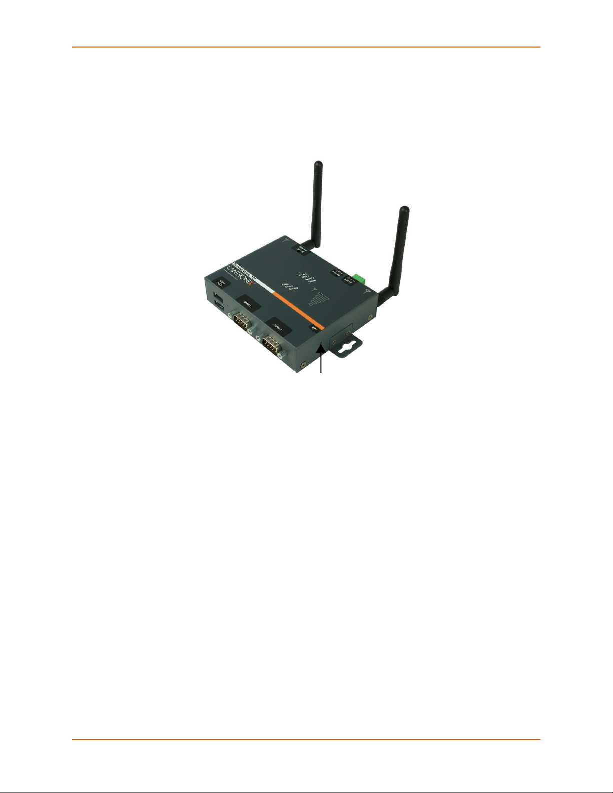
Hardware Components
Signal
Strength
LEDs
WPS
Button
(pin hole)
Front/Top Panel
Figure 3-1 shows the top panel view of the PremierWave XN unit. Table 3-11, Table 3-12,
Table 3-2, Table 3-3, Table 3-4 and Table 3-13 list and explain the behavior of the LEDs on the top
panel.
3: Installation of the PremierWave XN Device
Figure 3-1 PremierWave XN Unit
Table 3-2 PremierWave XN LEDs and Descriptions
LED Description
Power
WLAN
Serial 1
Serial 2
USB 1
USB 2
Fault/Diagnostic See Table 3-3 for diagnostic indications.
PremierWave® XN Intelligent Gateway User Guide 22
GREEN - displays a solid light when power is properly supplied
OFF - no power supplied
AMBER - flashes when the RX/TX packets are detected on the WLAN interface.
OFF - indicates WLAN interface is inactive or disabled
GREEN - flashes when Serial port 2 is transmitting data
AMBER - flashes when Serial port 2 is receiving data
OFF - when no data is being transmitted or received through Serial port 2
GREEN - flashes when Serial port 2 is transmitting data
AMBER - flashes when Serial port 2 is receiving data
OFF - when no data is being transmitted or received through Serial port 2
GREEN - displays a solid light when a USB device is connected to USB 1 Host
port and is functioning properly
OFF- when no USB device is connected to USB 1 Host port
GREEN - displays a solid light when a USB device is connected to USB 2 Host
port and is functioning properly.
OFF- when no USB device is connected to USB 2 Host port.
Page 23

3: Installation of the PremierWave XN Device
LED (continued) Description
Signal Strength Indicates WLAN signal strength when connection is established During WPS
negotiation and connection establishment, it reports status of WPS transaction.
When indicating the WLAN signal strength, see Table 3-12 for signal strength
information for connections in 5 GHz band or Table 3-11 for signal strength
information for connections in 2.4 GHz band.
For WPS status indications, see Table 3-4.
Table 3-3 Fault Conditions Indicated by Blink Patterns
Note: The fault LED blink patterns in this table are listed in order of priority.
Fault Conditions Blink Pattern
No Ethernet link detected. Long, long, short, short, 2 seconds off
(pattern repeats)
No IP obtained from Ethernet network when eth0
interface is enabled.
No WLAN link (no BSSIDSIM detected) Long, long, long, short, short, 2 seconds off
No IP obtained from WLAN network when wlan0
interface is enabled.
When the internal device temperature is above
operating limit.
When the internal device temperature is below
operating limit.
Primary power source (barrel connector) is undervolt (below 9 volts).
Secondary power source (terminal) is under-volt
(below 9 volts).
Long, long, short, short, short, 2 seconds off (pattern
repeats)
(pattern repeats)
Long, long, long, short, short, short, 2 seconds off
(pattern repeats)
Short, short, short, short, 2 seconds off
(pattern repeats)
Short, short, short, short, short, 2 seconds off
(pattern repeats)
Long, short, short (pattern repeats)
Long, short, short, short (pattern repeats)
Table 3-4 WPS Status Indicator
When the signal strength indicator is used to indicate WPS status, only one amber LED will be used.
WPS Status Blink Pattern
WPS is enabled and on Short, continuous
WPS has a profile error Long, long, long, short, short, 2 seconds off, continuous
WPS has a timeout error Long, long, long, short, short, short, short, 2 seconds off, continuous
Notes:
For Table 3-3 above, a “long” blink is 0.7 seconds of light followed by 0.3 seconds of no
light. A “short” blink is a light that is on for only 0.2 seconds and followed by 0.2 seconds
of no light.
The diagnostic blink patterns reflect the highest priority fault condition. Also, the
Diagnostic LED will give an initial, identifying blink pattern to indicate the type of diagnostic
information it will display. All power and other non-network related diagnostic patterns
begin with one long blink. All wired LAN related diagnostics patterns begin with two long
blinks. All WLAN-related diagnostics patterns begin with three long blinks.
PremierWave® XN Intelligent Gateway User Guide 23
Page 24

3: Installation of the PremierWave XN Device
2 USB Reset Serial 1 Serial 2
Ports Button
The PremierWave device has two male DB9 serial ports that support RS-232/422/485. Figure 3-5
shows the front view of the device. The default serial port settings are 9600 baud, 8 bits, no parity,
1 stop bit, no flow control.
Figure 3-5 PremierWave XN Male DB9 DTE Serial Ports
Figure 3-6 PremierWave XN Pinout Configuration for RS-232
Figure 3-7 PremierWave XN Pinout Configuration for Full Duplex RS-422/485 (4-wire)
Figure 3-8 PremierWave XN Pinout Configuration for Half Duplex RS-422/485 (2-wire)
PremierWave® XN Intelligent Gateway User Guide 24
Page 25

3: Installation of the PremierWave XN Device
Ethernet LEDs
The Ethernet port (see Figure 3-14) has two LEDs that indicate the status of the connection as
described in the Table 3-9 and Table 3-10 below:
Table 3-9 Left Ethernet LED
Color/Status Solid Light Blinking Pattern
Green 100 Mbps Link 100 Mbps Activity
Amber 10 Mbps Link 10 Mbps Activity
Table 3-10 Right Ethernet LED
Color/Status Solid Light
Green Full Duplex
OFF Half Duplex
The Ethernet port can connect to an Ethernet (10 Mbps) or Fast Ethernet (100 Mbps) network.
Table 3-11 WLAN Signal Strength Indicator at 2.4 GHz
Signal Strength Color & Number of LED Signal Bars
Greater than or equal to -60 dBm 5 Green
Greater than or equal to -65 dBm and less than -60 dBm 4 Green
Greater than or equal to -70 dBm and less than -65 dBm 3 Green
Greater than or equal to -75 dBm and less than -70 dBm 2 Amber
Greater than or equal to -80 dBm and less than -75 1 Amber
Less than -80 dBm All Off
Table 3-12 WLAN Signal Strength Indicator for 5 GHz
Signal Strength Color & Number of LED Signal Bars
Greater than or equal to -60 dBm 5 Green
Greater than or equal to -65 dBm and less than -60 dBm 4 Green
Greater than or equal to -70 dBm and less than -65 dBm 3 Green
Greater than or equal to -75 dBm and less than -70 dBm 2 Amber
Greater than or equal to -80 dBm and less than -75 1 Amber
Less than -80 dBm All Off
PremierWave® XN Intelligent Gateway User Guide 25
Page 26

3: Installation of the PremierWave XN Device
Antenna Terminal Barrel Ethernet Antenna
Block Plug
Power Power
(3-pin)
V-
V+
Table 3-13 WPS Status Indicator
When the signal strength indicator is used to indicate the WPS status, only one amber LED will be
used.
WPS Status Blink Pattern
WPS is enabled and on Short, continuous
WPS has a profile error Long, long, long, short, short, 2 seconds off, continuous
WPS has a timeout error Long, long, long, short, short, short, short, 2 seconds off, continuous
For Table 3-13 above, a “long” blink is 0.7 seconds of light followed by 0.3 seconds of
no light. A “short” blink is a light that is on for only 0.2 seconds and followed by 0.2
seconds of no light.
The diagnostic blink patterns reflect the highest priority fault condition. Also, the
Diagnostic LED will give an initial, identifying blink pattern to indicate the type of
diagnostic information it will display. All power and other non-network related
diagnostic patterns begin with one long blink. All wired LAN related diagnostics
patterns begin with two long blinks. All WLAN-related diagnostics patterns begin with
three long blinks.
Reset Button
You can reset the PremierWave XN intelligent gateway to factory defaults, including clearing the
network settings. The IP address, gateway, and netmask are set to 00s. To reset the unit to factory
defaults, perform the following steps.
1. Place the end of a paper clip or similar object into the reset opening (see Figure 3-5) and press
and hold down micro switch during a power cycle for 10-15 seconds.
2. Remove the paper clip to release the button. The unit will continue the boot process restoring
it back to the original factory default settings.
Back Panel
On the PremierWaveXN device is a 1 plug, 3-Pin Terminal Connector for Backup Power, and RJ45 Ethernet port as shown in Figure 3-14.
Figure 3-14 PremierWave XN Bottom/Back Panel View
PremierWave® XN Intelligent Gateway User Guide 26
Page 27
3: Installation of the PremierWave XN Device
WPS Button
(pin hole opening)
Antenna 2
Antenna 1
Wi-Fi Protected Setup (WPS)
Using WPS, you have the option of connecting to PremierWave XN devices with a router or
access point in a single operation instead of manually creating a profile with a network name
(SSID), setting up wireless security parameters and updating the choice list.
Figure 3-15 PremierWave XN WPS Button
To Start WPS
Using the Device
1. Place the end of a paper clip or similar object into the WPS opening (see Figure 3-15) and
press and hold down for a minimum of 5 seconds.
2. Remove the paper clip to release the button. The unit will start Wi-Fi protected setup.
Using the CLI
To enter the command level: enable -> config -> if 2 -> link
To Cancel WPS
Using the CLI
To enter the command level: enable -> config -> if 2 -> link
To Show WPS Status
Using the CLI
To enter the command level: enable -> config -> if 2 -> link
PremierWave® XN Intelligent Gateway User Guide 27
Page 28

Installing the PremierWave XN Device
Be sure to place or mount the device securely on a flat horizontal or vertical surface. The device
comes with brackets for mounting it, for example, on a wall. If using AC power, do not use outlets
controlled by a wall switch.
Observe the following guidelines when connecting the serial devices:
The PremierWave XN unit serial ports support RS-232/422/485.
Use a null modem cable to connect the serial port to another DTE device. Use a straight-
though (modem) cable to connect the serial port to a DCE device.
Connect your RJ-45 Ethernet cable to the RJ-45 port of the unit.
The PremierWave XN device supports a power range of 9 to 30 VDC. You can power up the
device with barrel-power connector and/or the 3-pin terminal connector for backup power supply.
Note: As soon as you plug the device into power, the device powers up automatically,
the self-test begins, and LEDs would indicate the device's status
Perform the following steps to install your device:
1. Connect PremierWave XN device to the serial ports.
3: Installation of the PremierWave XN Device
2. Connect an RJ-45 Ethernet cable between the unit and your Ethernet network.
3. Connect the antennas to the SMA connector on the backside. Do note that the safe distance
due to RF exposure from antenna is 23 cm.
Note: Antennas must be installed prior to powering on the unit. Do not remove or
connect the antennas while the unit power is on.
PremierWave® XN Intelligent Gateway User Guide 28
Page 29
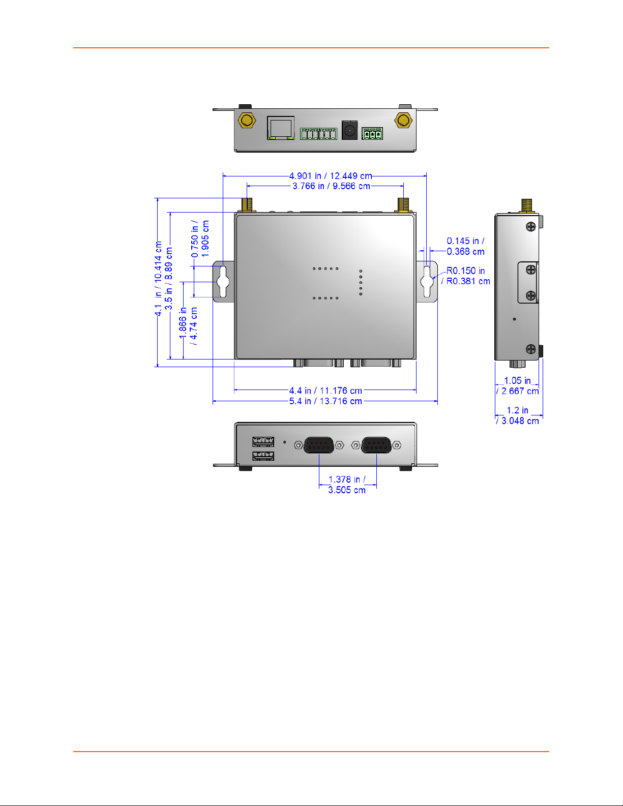
3: Installation of the PremierWave XN Device
Figure 3-16 PremierWave XN Unit Dimensions in Inches (in) and Centimeters (cm)
PremierWave® XN Intelligent Gateway User Guide 29
Page 30

4: Device Discovery and Quick Setup
Software embedded within the PremierWave XN intelligent gateway enables the device to be
easily discovered via the Ethernet network without any knowledge of the IP address or default
network configuration of the device.
The two methods supported are:
1. Accessing the PremierWave XN Device Using UPnP
2. Accessing the PremierWave XN Device Using DeviceInstaller
Accessing the PremierWave XN Device Using UPnP
This section covers the steps for locating a PremierWave XN unit and viewing its properties and
device details using UPnP (Network Discovery). You may also use the DeviceInstaller utility to
discover PremierWave XN units. See Accessing the PremierWave XN Device Using
DeviceInstaller on page 31.
The PremierWave XN units can be discovered automatically from Microsoft Windows® platforms
using UPnP (Network Discovery). UPnP enables devices to be discovered and a refreshed list of
devices available under "Network Places" within Windows Explorer as devices come online or go
offline.
Using the operations described below, it becomes a "plug and play" mechanism to reach the
device's Web UI (Web Manager) and complete the rest of the configuration.
Note: There is no new software to install as UPnP support is built-into Windows
operating systems, however it must be enabled on the Windows PC. Please see notes on
enabling UPnP (Network Discovery) on Windows XP and Windows 7 operating systems.
To search devices on Windows XP operating system:
1. Click Start->My Network Places. Lantronix PremierWave XN devices will be listed like other
network devices.
2. Double-click your device to view the device web page.
To search devices on Windows 7 operating system:
1. Click Start->Computer->Network. Lantronix PremierWave XN devices will be listed like other
network devices.
2. Double-click or right click your device and select "View device webpage " to view the device
web page.
To view device properties on Windows XP operating system:
1. Click Start->My Network Places. Lantronix PremierWave XN devices will be listed like other
network devices.
2. Right click your device and select Properties to view the device properties.
To search device properties on Windows 7 operating system:
1. Click Start->Computer->Network. Lantronix PremierWave XN devices will be listed like
other network devices.
2. Right click your device and select Properties to view the device properties.
PremierWave® XN Intelligent Gateway User Guide 30
Page 31

4: Device Discovery and Quick Setup
Accessing the PremierWave XN Device Using DeviceInstaller
This section covers the steps for locating a PremierWave XN unit and viewing its properties and
device details. The DeviceInstaller application is a free utility program provided by Lantronix that
discovers, configures, upgrades and manages Lantronix device servers.
Notes:
For instructions on using the DeviceInstaller utility to configure the IP address and
related settings or for more advanced features, see the DeviceInstaller Online Help.
Auto IP generates a random IP address in the range of 169.254.0.1 to
169.254.255.254, with a netmask of 255.255.0.0, if no BOOTP or DHCP server is
found. These addresses are not routable.
Accessing the PremierWave XN Device Using UPnP on page 30
Make note of the MAC address. It may be needed to perform various functions in
DeviceInstaller.
To use the DeviceInstaller utility, first install the latest version from the downloads page on the
Lantronix web site www.lantronix.com/downloads
1. Run the executable to start the installation process and respond to the installation wizard
prompts. (If prompted to select an installation type, select Typical.)
.
2. Click Start -> All Programs -> Lantronix -> DeviceInstaller 4.4 -> DeviceInstaller.
3. When DeviceInstaller starts, it will perform a network device search. To perform another
search, click Search.
4. Expand the PremierWave folder by clicking the + symbol next to the folder icon. The list of
available Lantronix PremierWave devices appears.
5. Select the PremierWave unit by expanding its entry and clicking on its IP address to view its
configuration.
6. On the right page, click the Device Details tab. The current PremierWave device
configuration appears. This is only a subset of the full configuration; the full configuration may
be accessed via Web Manager, CLI or XML.
Device Detail Summary
Note: The settings are Display Only in this table unless otherwise noted
Current Settings Description
Name Shows the PremierWave XN device name.
DHCP Device Name
Group Configurable field. Enter a group to categorize the PremierWave XN unit.
Displays one of the names the PremierWave XN device unit will send to the
DHCP server if it is configured to obtain an address in this manner.
Double-click the field, type in the value, and press Enter to complete. This
group name is local to this PC and is not visible on other PCs or laptops
using DeviceInstaller.
PremierWave® XN Intelligent Gateway User Guide 31
Page 32

4: Device Discovery and Quick Setup
Current Settings Description
Comments Configurable field. Enter comments for the PremierWave XN unit. Double-
click the field, type in the value, and press Enter to complete. This
description or comment is local to this PC and is not visible on other PCs or
laptops using DeviceInstaller.
Device Family Shows the PremierWave XN device family type as “PremierWave”.
Short Name Shows ”premierwave_xn” by default.
Long Name Shows “Lantronix PremierWave XN” by default.
Type
ID Shows the “PremierWave XN“ ID embedded within the unit.
Hardware Address Shows the PremierWave XN hardware (MAC) address.
Firmware Version Shows the firmware currently installed on the PremierWave XN unit.
Extended Firmware Version Provides additional information on the firmware version.
Online Status Shows the PremierWave XN unit status as Online, Offline, Unreachable
IP Address Shows the PremierWave XN current IP address. To change the IP address,
IPV6 Link Local Address Shows the PremierWave XN current IPv6 link local address.
IPV6 Global Address Shows the PremierWave XN current IPv6 global address.
IP Address was Obtained Appears “Dynamically” if the PremierWave XN device automatically
Subnet Mask Shows the subnet mask specifying the network segment on which the
Gateway Shows the IP address of the router of this network.
Interfaces Shows information about the Ethernet (eth0) and wireless (wlan0)
Number of Serial Ports Shows the number of serial ports on unit.
Supports Configurable Pins Shows False, indicating configurable pins are not available on the
Supports Email Triggers Shows True, indicating email triggers are available on the PremierWave XN
Telnet Supported Indicates whether Telnet is enabled on this PremierWave XN unit.
Telnet Port Shows the PremierWave XN port for Telnet sessions.
Web Port
Firmware Upgradeable Shows True, indicating the PremierWave XN firmware is upgradeable as
Shows the device type as “PremierWave
XN”.
(the PremierWave XN is on a different subnet), or Busy (the PremierWave
XN is currently performing a task).
click the Assign IP button on the DeviceInstaller menu bar.
received an IP address (e.g., from DHCP). Appears “Statically” if the IP
address was configured manually.
If the IP address was assigned dynamically, the following fields appear:
Obtain via DHCP with values of True or False.
Obtain via BOOTP with values of True or False.
PremierWave XN unit resides.
There is no default.
interfaces for your PremierWave XN unit. Click the + sign beside eth0 or
wlan0, and then the Status and Configuration subcategories to view status
and configuration information on these interfaces.
PremierWave XN unit.
unit
Shows the PremierWave XN port for Web Manager configuration (if Web
Enabled field is True).
newer versions become available.
PremierWave® XN Intelligent Gateway User Guide 32
Page 33

5: Configuration Using Web Manager
This chapter describes how to configure the PremierWave XN intelligent gateway using Web
Manager, the Lantronix browser-based configuration tool. The unit’s configuration is stored in nonvolatile memory and is retained without power. All changes take effect immediately, unless
otherwise noted. It contains the following sections:
Accessing Web Manager
Device Status Page
Web Manager Components
Navigating Web Manager
Accessing Web Manager
Note: You can also access the Web Manager by selecting the Web Configuration tab on
the DeviceInstaller application window.
To access Web Manager, perform the following steps:
1. Open a standard web browser. Lantronix supports the latest versions of Internet Explorer,
Mozilla Firefox, Safari, Opera or Chrome web browsers.
2. Enter the IP address or hostname of the PremierWave XN unit in the address bar. The IP
address may have been assigned manually using DeviceInstaller (see the PremierWave XN
Intelligent Gateway Quick Start Guide) or automatically by DHCP.
3. Enter your username and password. The factory-default username is “admin” and “PASS” is
the default password. The Device Status web page displays configurations including network
settings, line settings, tunneling settings, and product information.
PremierWave® XN Intelligent Gateway User Guide 33
Page 34

Device Status Page
Note: The Logout
button is available on
any web page. Logging
out of the web page
forces re-authentication
the next time the web
page is accessed.
The page is the first to appear after you log into Web Manager. The Device Status page also
appears when you click Status in the menu bar in Web Manager.
5: Configuration Using Web Manager
Figure 5-1 Device Status Page
PremierWave® XN Intelligent Gateway User Guide 34
Page 35

Web Manager Components
Menu Bar
Links to
subpages
Items to
configure
Information
and Help Area
Header
Configuration and/or Status Area
Footer
The layout of a typical Web Manager page is below.
Figure 5-2 Components of the Web Manager Page
5: Configuration Using Web Manager
Web Manager pages have these sections:
The menu bar always appears at the left side of the page, regardless of the page shown. The
menu bar lists the names of the pages available in the Web Manager. To bring up a page, click it in
the menu bar.
PremierWave® XN Intelligent Gateway User Guide 35
Page 36

5: Configuration Using Web Manager
The main area of the page has these additional sections:
Links near the top of many pages, such as the one in the example above, enable you to link to
additional subpages. On some pages, you must also select the item you are configuring, such
as a tunnel.
In the middle of many pages, you can select or enter new configuration settings. Some pages
show status or statistics in this area rather than allow you to enter settings.
At the bottom of most pages, the current configuration is displayed. In some cases, you can
reset or clear a setting.
When a parameter is changed on the page, a Submit button will appear. Click on this button
to save the change.
The information or help area shows information or instructions associated with the page.
A Logout link is available at the upper right corner of every page. In Chrome or Safari, it is
necessary to close out of the browser to completely logout. If necessary, reopen the browser
to log back in.
The footer appears at the very bottom of the page. It contains copyright information and a link
to the Lantronix home page.
Navigating Web Manager
The Web Manager provides an intuitive point-and-click interface. A menu bar on the left side of
each page provides links you can click to navigate from one page to another. Some pages are
read-only, while others let you change configuration settings.
Note: There may be times when you must reboot the PremierWave XN device for the
new configuration settings to take effect. The chapters that follow indicate when a change
requires a reboot. Anytime you reboot the unit, this operation will take some time to
complete. Please wait a minimum of 25-30 seconds after rebooting the unit before
attempting to make any subsequent connections.
Web Manager Page Description See
Status Shows product information, network, line, and tunneling settings. 34
Actions Allows you to view and configure the actions for a specific alarm or report. 71
Applications Allows you to view and configure Application settings. 74
Bridge Allows you to configure a bridge and shows the current operational state
of the bridge.
CLI Shows Command Line Interface (CLI) statistics and lets you change the
current CLI configuration settings.
Clock Allows you to view and configure the current date, time and time zone as it
displays in web manager.
Diagnostics Lets you perform various diagnostic procedures. 97
Table 5-3 Web Manager Pages
Page
109
103
101
Discovery Allows you to view and modify the configuration and statistics for device
discovery.
133
PremierWave® XN Intelligent Gateway User Guide 36
Page 37

5: Configuration Using Web Manager
Web Manager Page
(continued)
DDNS Alllows you to view and configure DDNS settings. 67
DNS Shows the current configuration of the DNS subsystem and the DNS
Email Shows email statistics and lets you clear the email log, configure email
Filesystem Shows file system statistics and lets you browse the file system to view a
FTP Shows statistics and lets you change the current configuration for the File
Gateway Shows statistics and lets you change the current configuration for the
GRE Alllows you to view and configure GRE settings. 70
Host Lets you view and change settings for a host on the network. 91
HTTP Shows HyperText Transfer Protocol (HTTP) statistics and lets you change
Line Shows statistics and lets you change the current configuration and
Modbus Shows the current connection status of the Modubs servers listening on
Network Shows status and lets you configure the network interface. 38
Description See
Page
127
cache.
134
settings, and send an email.
93
file, create a file or directory, upload files using HTTP, copy a file, move a
file, or perform TFTP actions.
128
Transfer Protocol (FTP) server.
61
gateway.
129
the current configuration and authentication settings.
76
Command mode settings of a serial line.
122
the TCP ports and configure Modbus TCP server.
Protocol Stack Lets you perform lower level network stack-specific activities. 95
RSS Lets you change current Really Simple Syndication (RSS) settings. 131
SMTP Shows and allows modification of the current configuration of SMTP. 134
SNMP Shows and allows modification of the current configuration of SNMP. 134
SSH Lets you change the configuration settings for SSH server host keys, SSH
server authorized users, SSH client known hosts, and SSH client users.
SSL Lets you upload an existing certificate or create a new self-signed
certificate.
Syslog Lets you specify the severity of events to log and the server and ports to
which the syslog should be sent.
System Lets you reboot device, restore factory defaults, upload new firmware, and
change the device long and short names.
Terminal Lets you change current settings for a terminal. 90
Tunnel Lets you change the current configuration settings for an incoming tunnel
connection.
VPN Lets you view and configure VPN settings.
WLAN Profiles Lets you view, edit, delete and create a WLAN profile on a device. 51
WLAN Quick Connect Lets you change configuration settings for the Quick Connect. 60
XML Lets you export XML configuration and status records, and import XML
configuration records.
115
118
128
102
79
67
105
PremierWave® XN Intelligent Gateway User Guide 37
Page 38

6: Network Settings
The Network Settings show the status of the Ethernet and WLAN device interface/link and lets you
configure the settings on the device. Interface settings are related to the configuration of the IP
and related protocols. Link settings are related to the physical link connection, which carries the IP
traffic.
The PremierWave XN device server contains two network interfaces. Both interfaces will be
activated and controlled by the bridging subsystem when bridging is enabled.The Ethernet
interface is called Network 1 or eth0, and the WLAN interface is called Network 2 or wlan0
Notes:.
Some settings require a reboot to take effect. These settings are noted below.
Wait a minimum of 25-30 seconds after rebooting the unit before attempting to make
any subsequent connections.
The blue text in the XML command strings of this chapter are to be replaced with a
user-specified name.
Network 1 Status
In the Network 1 status pages, you can view both the current interface operational settings as well
as the settings that would take effect upon a device reboot, as well as Link, QoS and Failover
status information.
To view Ethernet (eth0) Interface status, click Network on the menu and select Network 1 ->
Interface -> Status.
To view Ethernet (eth0) Link status, click Network on the menu and select Network 1 -> Link
-> Status.
To view Ethernet (eth0) QoS status, click Network on the menu and select Network 1 -> QoS
-> Status.
To view Ethernet (eth0) Failover status, click Network on the menu and select Network 1 ->
Failover -> Status.
Network 1 (eth0) Interface Settings
Table 6-1 shows the network interface settings that can be configured.
These settings apply to both the Network 1 Ethernet (eth0) and the Network 2 WLAN (wlan0)
interfaces, but are configured independently for each interface.
Table 6-1 Network Interface Settings
Network Interface
Settings
State Select to enable or disable the interface.
IPv4 State Select to enable of disable the IPv4 state.
Description
PremierWave® XN Intelligent Gateway User Guide 38
Page 39

6: Network Settings
Network Interface
Settings (continued)
BOOTP Client Select to turn On or Off. At boot up, after the physical link is up, the PremierWave
DHCP Client
Priority Priority ranges from 0-10.
IP Address
Default Gateway
Hostname
Domain
DHCP Client ID
Primary DNS
Secondary DNS
MTU
Description
XN device will attempt to obtain IPv4 settings from a BOOTP server.
Note: Overrides the configured IPv4 address/mask, gateway, hostname, and
domain. When DHCP is Enabled, the system automatically uses DHCP,
regardless of whether BOOTP is Enabled. Changing this value requires you to
reboot the device.
Select to turn On or Off. At boot up, after the physical link is up, the PremierWave
XN unit will attempt to obtain IPv4 settings from a DHCP server and will
periodically renew these settings with the server.
Note: Overrides BOOTP, the configured IPv4 address/mask, gateway, hostname,
and domain. Changing this value requires you to reboot the device.
Note: Within Web Manager, click Renew to renew the DHCP lease.
Note: Lower priority number means higher preference.
Enter the static IPv4 address to use for the interface. You may enter it alone or in
CIDR format.
Note: This setting will be used if Static IP is active (both DHCP and BOOTP are
Disabled). Changing this value requires you to reboot the device. When DHCP or
BOOTP is enabled, the PremierWaveXN device tries to obtain an IPv4 address
from a DHCP or BOOTP server. If it cannot, the PremierWave XN unit generates
and uses an Auto IP address in the range of 169.254.xxx.xxx, with a network mask
of 255.255.0.0.
Enter the IPv4 address of the router for this network.
Note: This setting will be used if Static IP is active (both DHCP and BOOTP are
Disabled).
Enter the hostname for the interface. It must begin with a letter or number, continue
with a sequence of letters, numbers, or hyphens, and end with a letter or number.
This setting will take effect immediately, but will not register the hostname with a
DNS server until the next reboot.
Enter the domain name suffix for the interface.
Note: This setting will be used when either Static IP or Auto IP is active, or if
DHCP/BOOTP is active and no Domain Suffix was acquired from the server.
Enter the ID if the DHCP server requires a DHCP Client ID option. The DHCP
server’s lease table shows IP addresses and MAC addresses for devices. The
lease table shows the Client ID, in hexadecimal notation, instead of the
PremierWave
Enter the IP address of the primary Domain Name Server.
Note: This setting will be used when either Static IP or Auto IP is active, or if
DHCP/BOOTP is active and no DNS server was acquired from the server.
Enter the IP address of the secondary Domain Name Server.
Note: This setting will be used when either Static IP or Auto IP is active, or if
DHCP/BOOTP is active and no DNS server was acquired from the server.
When DHCP is enabled, the MTU size is (usually) provided with the IP address.
When not provided by the DHCP server, or using a static configuration, this value
is used. The MTU size can be from 576 to 1500 bytes, the default being 1500
bytes.
XN intelligent gateway MAC address.
PremierWave® XN Intelligent Gateway User Guide 39
Page 40

6: Network Settings
Network Interface
Description
Settings (continued)
IPv6 State Select to enable of disable the IPv4 state.
IPv6 DHCP Client Select to turn On or Off.
On: will provide an additional IPv6 addres in addition to the displayed Link Local
IPv6 address and DHCPv6 IPv6 address. This is the auto configuration address
provided by the IPv6 router.
Off: will not display auto configured IPv6 address in CLI or WebUI.
IPv6 Address Enter the static IPv6 address to use for the interface.
Note: This setting is used if Static IPv6 is active (DHCPv6 is Disabled). Changing
this value requires a reboot. When DHCPv6 is enabled, the XPort Pro Lx6 tries to
obtain an IPv6 address from a DHCPv6 server. If it cannot, then XPort Pro Lx6
generates and uses a Link local IPv6 address.
IPv6 Default Gateway Enter the default IPv6 Default Gateway.
IPv6 Domain Enter the IPv6 domain name suffix for the interface.
Note: This setting will be used when either Static IP or Auto IP is active, or if
DHCP/BOOTP is active and no Domain Suffix was acquired from the server.
IPv6 Primary DNS Enter the IPv6 address of the primary Domain Name Server.
Note: This setting will be used when either Static IP or Auto IP is active, or if
DHCP/BOOTP is active and no DNS server was acquired from the server.
IPv6 Secondary DNS Enter the IPv6 address of the secondary Domain Name Server.
Note: This setting will be used when either Static IP or Auto IP is active, or if
DHCP/BOOTP is active and no DNS server was acquired from the server.
To Configure Network 1 Interface Settings
Using Web Manager
To modify Ethernet (eth0) settings, click Network on the menu and select Network 1 ->
Interface -> Configuration.
Using the CLI
To enter the eth0 command level: enable -> config -> if 1
Using XML
Include in your file: <configgroup name="interface" instance="eth0">
PremierWave® XN Intelligent Gateway User Guide 40
Page 41

Network 1 (eth0) Link Settings
Physical link parameters can be configured for an Ethernet (eth0) Network Link (see
Table 6-2) and a WLAN (wlan0) Link Interface (see Table 6-6).
Table 6-2 Network 1 (eth0) Link Settings
6: Network Settings
Network 1 Ethernet (eth0)
Link Settings
Speed
Duplex
Description
Select the Ethernet link speed. (Default is Auto)
Auto = Auto-negotiation of Link Speed
10 Mbps = Force 10 Mbps
100 Mbps = Force 100 Mbps
Select the Ethernet link duplex mode. (Default is Auto)
Auto = Auto-negotiation of Link Duplex
Half = Force Half Duplex
Full = Force Full Duplex
Notes:
When speed is Auto, duplex must be Auto or Half.
When speed is not Auto, duplex must be Half or Full.
Fixed speed Full duplex will produce errors connected to Auto, due to duplex
mismatch.
To Configure Network 1 Link Settings
Using Web Manager
To modify Ethernet (eth0) Link information, click Network on the menu and select Network 1
> Link > Configuration.
Using the CLI
To enter the eth0 Link command level: enable -> config -> if 1 -> link
Using XML
Include in your file: <configgroup name="ethernet" instance="eth0">\
Network 1 (eth0) QoS
QoS (Quality of Service) can be enabled and configured for both Network 1 (eth0) and Network 2
(wlan0). If enabled, the router will control the flow of outbound traffic according to the user-defined
filters. In other words, QoS improves performance by allowing the user to prioritize applications.
Filters can be defined to prioritize traffic based on the source or destination network, source or
destination port, or the source MAC address. Up to 32 user-defined filters can be added. The
following are predefined priority classes:
Network Control and Internetwork Control are typically used for network control packets such
as ICMP and have the highest priorities.
PremierWave® XN Intelligent Gateway User Guide 41
Page 42

6: Network Settings
Move bandwidth allocation is a minimum 5% each to Network control.
Voice: Bandwidth allocation is minimum 30%.
Video: Bandwidth allocation is minimum 20%.
Critical Applications: Bandwidth allocation is minimum 15%.
Excellent Effort: Bandwidth allocation is minimum 10%.
Best Effort: Bandwidth allocation is minimum 10%.
Background: Bandwidth allocation is minimum 5% and has the lowest priority.
Table 6-3 shows the network QoS settings that can be configured including adding new filters.
Table 6-3 Network 1 (eth0) QoS Settings
Network 1 (eth0) Settings Description
State Click to enable or disable state.
Import filters Click to enable or disable import filters to import configurations from other
interfaces.
Uplink Speed Enter the maximum uplink speed. Set 0 to set speed to default.
Delete Click the checkbox to the left of any existing QoS filter to be deleted and
click the Submit button.
Filter type Select the filter type from the drop-down window:
Network
Port
Network Enter the Network, if the Network filter type is selected.
Ports Enter the Port, if the Port filter type is selected.
Priority Select the priority of the filter from the drop-down menu.
To Configure Network 1 QoS Settings
Using Web Manager
To modify Ethernet 1 (eth0) QoS information, click Network on the menu and select Network
1 > QoS > Configuration.
Using the CLI
To enter the eth0 QoS command level: enable -> config -> if 1 -> qos
Using XML
Include in your file: <configgroup name="qos" instance="eth0">
PremierWave® XN Intelligent Gateway User Guide 42
Page 43

Network 1 (eth0) Failover
The PremierWave XN intelligent gateway provides WAN network failover, in the form of a "dead
remote host reachability" mechanism (essentially a ping against a known host). If the remote host
is determined to be not reachable, the device will failover to the Wi-Fi interface. If the remote host
is determined to be reachable, the device will failback to the Ethernet interface.
Table 6-4 Network 1 (eth0) Failover Settings
6: Network Settings
Network 1 (Failover)
Settings
State Click to enable or disable state.
Failover Interface
Hostname Enter the remote host to test reachability.
Method Select ICMP or TCP based ping.
Timeout Indicate the interval to wait for ping response from remote host.
Interval Indicate the interval in which to test reachability
Failover Threshold Indicate the allowed number of failed pings – after which the device will
Failback Threshold Indicate the number of successful pings – after which the device will failback
Description
Always select
failover to the wlan0 interface.
to the Ethernet interface.
wlan0 in the PremierWave XN intelligent gateway.
To Configure Network 1 Failover Settings
Using Web Manager
To modify Failover settings, click Network on the menu and select Network 1 > Failover >
Configuration.
Using the CLI
To enter the eth0 link command level: enable -> config -> if 1 -> failover
Using XML
Include in your file: <configgroup name="network failover" instance="eth0">
Network 2 Status
In the Network 2 status pages, you can view both the current interface operational settings as well
as the settings that would take effect upon a device reboot, as well as Link, QoS and Failover
status information.
To view Ethernet (wlan0) Interface status, click Network on the menu and select Network 2 -
> Interface -> Status.
To view Ethernet (wlan0) Link status, click Network on the menu and select Network 2 ->
Link -> Status.
PremierWave® XN Intelligent Gateway User Guide 43
Page 44

To view Ethernet (wlan0) QoS status, click Network on the menu and select Network 2 ->
QoS -> Status.
To view Ethernet (wlan0) Failover status, click Network on the menu and select Network 2 ->
Failover -> Status.
Network 2 (wlan0) Interface Settings
This page is used to view the status of the wlan0 interface on the device.
Note: Statistics are as measured by the device since bootup. Your service provider may
account for data usage differently.
This page is used to configure the wlan0 interface on the device. To see the effect of these items
after a reboot, view the Status page.
Table 6-5 Network 2 (wlan0) Interface Settings
6: Network Settings
Network 2 (wlan0)
Interface Settings
State Select to enable or disable the interface.
IPv4 State Select to enable of disable the IPv4 state.
BOOTP Client Select to turn on or off the BOOTP client.
DHCP Client Select to turn on or off the DHCP client.
Priority It ranges from 0-10.
IP Address Enter the IP address alone, in CIDR form, or with an explicit mask.
Default Gateway Enter the default gateway.
Hostname Enter the host name, beginning with a letter, continue with a letter, number or
Domain Enter the domain for the interface.
DHCP Client ID Enter the DHCP client ID.
Primary DNS Enter the IP address of the primary Domain Name Server.
Secondary DNS Enter the IP address of the secondary Domain Name Server.
MTU Enter the maximum transmission unit (MTU) associated with the interface.
IPv6 State Select to enable of disable the IPv4 state.
IPv6 DHCP Client Select to turn On or Off.
Description
Note: Lower priority number means higher preference.
hyphen and end with a letter or a number.
Note: This setting will be used when either Static IP or Auto IP is active, or if
DHCP/BOOTP is active and no DNS server was acquired from the server.
Note: This setting will be used when either Static IP or Auto IP is active, or if
DHCP/BOOTP is active and no DNS server was acquired from the server.
On: will provide an additional IPv6 addres in addition to the displayed Link
Local IPv6 address and DHCPv6 IPv6 address. This is the auto configuration
address provided by the IPv6 router.
Off: will not display auto configured IPv6 address in CLI or WebUI.
PremierWave® XN Intelligent Gateway User Guide 44
Page 45

6: Network Settings
Network 2 (wlan0)
Interface Settings
IPv6 Address Enter the static IPv6 address to use for the interface.
IPv6 Default Gateway Enter the default IPv6 Default Gateway.
IPv6 Domain Enter the IPv6 domain name suffix for the interface.
IPv6 Primary DNS Enter the IPv6 address of the primary Domain Name Server.
IPv6 Secondary DNS Enter the IPv6 address of the secondary Domain Name Server.
Description
Note: This setting is used if Static IPv6 is active (DHCPv6 is Disabled). Changing
this value requires a reboot. When DHCPv6 is enabled, the XPort Pro Lx6 tries to
obtain an IPv6 address from a DHCPv6 server. If it cannot, then XPort Pro Lx6
generates and uses a Link local IPv6 address.
Note: This setting will be used when either Static IP or Auto IP is active, or if
DHCP/BOOTP is active and no Domain Suffix was acquired from the server.
Note: This setting will be used when either Static IP or Auto IP is active, or if
DHCP/BOOTP is active and no DNS server was acquired from the server.
Note: This setting will be used when either Static IP or Auto IP is active, or if
DHCP/BOOTP is active and no DNS server was acquired from the server.
To Configure Network 2 Interface Settings
Using Web Manager
To modify network 2 wlan0 interface information, click Network on the menu and select
Network 2 > Interface > Configuration.
Using the CLI
To enter the wlan0 command level: enable -> config -> if 2
Using XML
Include in your file: <configgroup name = "interface” instance = “wlan0”>
SmartRoam
The SmartRoam utility monitors the signal strengths of all in-range access points belonging to the
Extended Service Set (ESS) to which the PremierWave
found with a signal strength which is significantly greater than that of the currently associated AP,
the SmartRoam utility automatically switches to the new AP. This reduces interruptions in wireless
connectivity and ensures optimal signal strength. Roaming happens automatically and is
completely transparent to the user; no loss of network connectivity should occur.
The SmartRoam utility periodically scans for access points which belong to the current ESS
(having the same SSID and security settings at the currently associated AP.) The results are then
searched for an AP with a 'stronger' signal (higher RSSI) than the current AP. If the search is
successful, SmartRoam triggers a disconnection from the current AP and a connection to the one
selected from the scan results.
XN is currently connected. When an AP is
Since moving between access points is a time-consuming process which can negatively impact
throughput, SmartRoam employs a delta value to ensure that the move only occurs if there would
be a significant gain in signal strength. When searching the results of a scan, SmartRoam only
considers the APs with RSSI exceeding that of currently associated AP by at least the delta value.
PremierWave® XN Intelligent Gateway User Guide 45
Page 46

Note: RSSI is reported in two different ways. When displayed in scan results the RSSI is
an instantaneous value obtained from a single beacon/probe response, and therefore may
vary across scan results. When reported in the status of the current connection (for the
associated access point) the value is averaged over time and is less prone to fluctuation.
Network 2 (wlan0) Link Settings
This page shows configuration of an wlan0 link on the device.
Table 6-6 Network 2 (wlan0) Link Settings
Network 2 Link Settings Description
Choice 1 Profile
Choice 2 Profile
Choice 3 Profile
Choice 4 Profile
Out of Range Scan Interval Set the amount of time in seconds, between SmartRoaming scans.
Roaming Click to Enable or Disable SmartRoaming.
RSSI Delta The minimum difference (in dBm) between the current RSSI and the RSSI
Debugging Level
Active Channel Scan Time
Passive Channel Scan
Time
Radio Band Selection
WLAN Watchdog Select to enable or disable.
Select up to four (4) WLAN Profiles for automatic connection to wireless
networks. More information on wireless settings is available in the
section, To Configure Network 2 Link Settings on page 46.
Enter the name of the WLAN Profile desired for each choice.
of any access point in the scan results before it will be considered as a
roaming candidate. The configured value will actually be used for the highpower delta. The roaming delta is cut in half for RSSI below -50 dBm. The
value for the low-power delta will be derived from the configured one by
dividing it by two. Default value: 24 dBm, range: 14 - 24 dBm.
Set the verbosity level for printing WLAN Link messages to the TLOG
(Default is Info).
Set the amount of time, in milliseconds, the radio will dwell on each
individual channel when performing an active scan. During active scanning,
the radio transmits prove requests and gathers prove responses from other
devices. The range of values is 50 to 150 msec.
Set the amount of time, in milliseconds, the radio will dwell on each
individual channel when performing a passive scan. During passive
scanning the radio does not transmit probe requests, instead relying on
beacons sent by other devices. The range of values is 100 to 400 msec.
Select the band(s) on which the radio will operate. Options are 2.4 GHz
only, 5 GHz only or Dual band.
6: Network Settings
To Configure Network 2 Link Settings
Using Web Manager
To modify network 2 wlan0 interface information, click Network on the menu and select
Network 2 > Link > Configuration.
PremierWave® XN Intelligent Gateway User Guide 46
Page 47

Using the CLI
To enter the link command level: enable -> if 2 -> link
Using XML
6: Network Settings
Include in your file:
<configgroup n
Network 2 (wlan0) QoS
QoS (Quality of Service) can be enabled and configured for both Network 1 (eth0) and Network 2
(wlan0). If enabled, the router will control the flow of outbound traffic according to the user-defined
filters. In other words, QoS improves performance by allowing the user to prioritize applications.
Filters can be defined to prioritize traffic based on the source or destination network, source or
destination port, or the source MAC address. Up to 32 user-defined filters can be added. The
following are predefined priority classes:
Network Control and Internetwork Control are typically used for network control packets such
as ICMP and have the highest priorities.
Bandwidth allocation is a minimum 5% each.
Voice: Bandwidth allocation is minimum 30%.
Video: Bandwidth allocation is minimum 20%.
Critical Applications: Bandwidth allocation is minimum 15%.
Excellent Effort: Bandwidth allocation is minimum 10%.
Best Effort: Bandwidth allocation is minimum 10%.
Background: Bandwidth allocation is minimum 5% and has the lowest priority.Table 6-7 shows the
network QoS settings that can be configured including adding new filters.
ame = "wlan link
" instance = "wlan0">
Table 6-7 Network 2 (wlan0) QoS Settings
Network 2 (QoS) Settings Description
State Click to enable or disable state.
Import filters Click to enable or disable import filters to import configurations from other
interfaces.
Uplink Speed Enter the maximum uplink speed. Set 0 to set speed to default.
Table 6-8 Adding or Deleting Network 2 (wlan0) QoS Settings
Adding or Deleting
Network 2 (QoS) Settings
Delete Click the checkbox to the left of any existing QoS filter to be deleted and
Filter type Select the filter type from the drop-down window:
Description
click the Submit button.
Mac Address
Network
Port
PremierWave® XN Intelligent Gateway User Guide 47
Page 48

6: Network Settings
Adding or Deleting
Network 2 (QoS) Settings
MAC Address Enter the MAC address, if the MAC Address filter type is selected.
Network Enter the Network, if the Network filter type is selected.
Ports Enter the Port, if the Port filter type is selected.
Priority Select the priority of the filter from the drop-down menu.
Description
To Configure Network 2 QoS Settings
Using Web Manager
To modify Ethernet (eth0) QoS information, click Network on the menu and select Network 2
> QoS > Configuration.
Using the CLI
To enter the eth0 QoS command level: enable -> config -> if 2 -> qos
Using XML
Include in your file: <configgroup name="qos" instance="wlan0">
WLAN Link Status and Scan Commands
These commands display information about the current state of the wireless network.
Table 6-9 Network 2 Link Scan
WLAN Link Information
Commands
Network Name Enter the Service Set Identifier (network name) of the device, if known. If the
Scan “<network SSID>”
Refresh scan results
every 60 seconds
(checkbox)
Description
field is kept empty, the scan performed will search for all available wireless
devices.
Perform a scan for devices within range of the device server. Including the
optional network SSID limits the scan to devices configured with the specified
network SSID. Omitting the network SSID performs a scan for all devices in
range.
Note: When omitting the network SSID it is still necessary to include the
opening and closing quotation marks (scan “”). When the PremierWave unit is
associated with an access point, scanning is only preformed on the band on
which the unit is connected.
Check this to auto update the list of networks every 60 seconds.
Uncheck this to stop auto update.
The results of the scan command are presented in the following format in the table below:
PremierWave® XN Intelligent Gateway User Guide 48
Page 49

6: Network Settings
Table 6-10 Network 2 Link Scan Results on Web Manager
WLAN Link Scan Results Field Description
SSID Service Set Identifier (network name) of the device. Clicking a specific
SSID brings you to the specific WLAN profile of the device selected.
See WLAN Profiles (on page 51) for more information.
BSSID Basic Service Set Identifier. AdHoc mode is limited to four
connections.
Ch (Channel) The channel on which the device is operating.
RSSI The instantaneous Received Signal Strength Indicator (RSSI) of the
device measured in dBm.
Note: RSSI reported in scan results is a single sampling, while the
RSSI reported in the 'status' command (showing the signal strength of
the currently connected AP) is averaged over time.
Security Suite Indicates the security suite in use by the device as well as whether it is
operating in Adhoc (IBSS) mode.
The results of the status command are presented in the following format:
Table 6-11 Network 2 Link Status
WLAN Link Status Description
Connection State Indicates the connection state.
BSSID A unique identifier for the Basic Service Set corresponding to the
MAC address of the Access Point in infrastructure mode, or a
generated value in Adhoc mode. AdHoc mode is limited to four
connections.
SSID The Service Set Identifier of the connected network.
Topology The type of wireless network in use for the current association
(Adhoc or Infrastructure).
Active WLAN Profile Indicates which WLAN profile created the current connection to
the wireless network.
Pairwise Cipher The standard used to encrypt a particular type of data in the
current wireless association.
Group Cipher The standard used to encrypt a particular type of data in the
current wireless association.
Security Suite Indicates the security suite used for the current association.
Channel The channel used for the current association.
WPS Mode Indicates whether WPS is activated.
Frequency Frequency (in MHz) on which the current connection is operating.
IPv6 Link-local Address Indicates the IPv6 link-local address.
PremierWave® XN Intelligent Gateway User Guide 49
Page 50

6: Network Settings
To View WLAN Link Scan and Status Information
Using Web Manager
To scan the wireless (wlan0) Link, click Network in the menu and select Network 2 -> Link ->
Scan.
To view the wireless (wlan0) Link status information, click Network in the menu and select
Network 2 -> Link -> Status.
Using the CLI
To enter the wlan0 Link command level: enable -> config -> if 2 -> link
Using XML
Include in your file:
<statusgroup name="interface" instance="wlan0">
and
<statusgroup name="wlan scan"></statusgroup>
Network 2 (wlan0) Failover
The PremierWave XN intelligent gateway provides wlan0 failover, in the form of a "dead remote
host reachability" mechanism (essentially a ping against a known host). If the remote host is
determined to be not reachable, the device will failover to the Ethernet interface. If the remote host
is determined to be reachable, the device will failback to the Wi-Fi interface.
Table 6-12 Network 2 (wlan0) Failover Settings
Network 1 (Failover)
Settings
State Click to enable or disable state.
Failover Interface
Hostname Enter the remote host to test reachability.
Method Select ICMP or TCP based ping.
Timeout Indicate the interval to wait for ping response from remote host.
Interval Indicate the interval in which to test reachability
Failover Threshold Indicate the allowed number of failed pings – after which the device will
Failback Threshold Indicate the number of successful pings – after which the device will failback
Description
Always select eth0 in the PremierWave
failover to the wlan0 interface.
to the Ethernet interface.
XN intelligent gateway.
PremierWave® XN Intelligent Gateway User Guide 50
Page 51

To Configure Network 2 Failover Settings
Using Web Manager
To modify Failover settings, click Network on the menu and select Network 2 > Failover >
Configuration.
Using the CLI
To enter the wlan0 link command level: enable -> config -> if 2 -> failover
Using XML
Include in your file: <configgroup name="network failover" instance="wlan0">
WLAN Profiles
A WLAN profile defines all of the settings necessary to establish a wireless connection with either
an access point (in infrastructure mode) or another wireless client (in Adhoc mode, limited to four
connections.) A maximum of eight profiles can exist on the PremierWave XN intelligent gateway
at a time. All enabled profiles are active.
6: Network Settings
The PremierWave unit now supports dynamic profiles and prioritization of the profiles. Dynamic
Profiles are the ones created via WPS or QuickConnect. Profiles are numbered based on priority.
Dynamic profiles (in reversed order of creation), choice list profiles (Choice1, Choice2, Choice3,
and Choice4), and then the remaining profiles. Use the number from output of 'show' command.
To Configure WLAN Profiles
You can view, edit, create or delete a WLAN profile.
Using WebManager
Click WLAN Profiles on the menu.
Using the CLI
To enter the wlan0 Profile command level: enable -> config -> wlan profiles
Using XML
Include in your file: <configgroup name="wlan profile"
instance="profile_name">
PremierWave® XN Intelligent Gateway User Guide 51
Page 52

6: Network Settings
Table 6-13 Creating, Deleting or Enabling WLAN Profiles
WLAN Profile Basic Settings Description
Delete (checkbox) Click the Delete checkbox beside the profile(s) to be deleted. Three
buttons will appear:
Click the Submit button to permanently delete profile(s).
Click the Apply button to delete the profile for testing purposes. If the
device reboots, this change will not be applied.
Click the Cancel button to cancel this action, as desired.
Enabled (checkbox) Click the Enabled checkbox beside the profile(s) to be enabled. Three
buttons will appear:
Click the Submit button to permanently enable profile(s).
Click the Apply button to enable the profile for testing purposes. If the
device reboots, this change will not be applied.
Click the Cancel button to cancel this action, as desired.
View or Edit
(link to specific profile)
Create new profile Type in the name of the new profile to be created into the Create new
Click on a specific WLAN Profile name to edit the WLAN profile basic
settings (see Table 6-14).
profile field. Then, click the Submit button which appears to create the
profile. Once created, the profile name may be clicked so you may edit
profile settings (see Table 6-14).
Table 6-14 WLAN Profile Basic Settings
WLAN Profile Basic Settings Description
Network Name (SSID) Specify the name of the wireless network (SSID.)
Warning: Creating a new profile with a pre-existing network
name will cause the original network name and associated profile
to be overwritten.
State Select to Enable or Disable.
Topology Specify Infrastructure (ESS) or Adhoc (IBSS) mode.
Infrastructure: mode that communicates with access points.
Adhoc: mode that communicates with other clients, limited to four
connections.
Channel Specify the channel for an Adhoc network.
Note: This setting only applies to the creation of an Adhoc network.
Radio Mode Select the radio mode for the WLAN profile.
Scan DFS Channels Select to Enable or Disable scanning on the DFS (Dynamic Frequency
Selection) channels in the 5 GHz band.
Note: This setting only applies if scanning in the 5 GHz band is enabled.
To Configure WLAN Profile Basic Settings
Using Web Manager
To view or edit an existing WLAN profile or to create a new profile, click WLAN Profiles on the
menu and select an existing profile.
PremierWave® XN Intelligent Gateway User Guide 52
Page 53

6: Network Settings
Using the CLI
To enter the wlan0 Profile command level: enable -> config -> wlan profiles
-> edit <profile number> or enable -> config -> wlan profiles -> edit
<profile name>
Using XML
Include in your file:
<configgroup name=”wlan profile” instance=”profile name”>
and
<configitem name=”basic”>
Table 6-15 WLAN Profile Advanced Settings
WLAN Profile Advanced Settings Description
TX Data Rate Maximum
Note: This setting only applies if ‘TX Data Rate’ is set to ‘Fixed’.
Specify the type of transmission data rate:
Specify the rate for data transmission.
TX Data Rate
Fixed = keeps the transmission rate at the configured value.
Auto-reduction = allows the PremierWave XN intelligent gateway
to reduce the data rate automatically, depending on link quality.
TX Power Maximum Specify the maximum transmission output power in dBm.
Select the antenna the radio will use or allow PremierWave XN unit to
automatically make the selection.
Antenna Diversity
Enabled = allows the PremierWave XN unit to select the antenna.
Antenna 1 = use antenna closest to Ethernet port.
Antenna 2 = use antenna closest to power input.
Max Missed Beacons Enter the maximum number of missed beacons allowed.
Select to Enable or Disable power management, which reduces the
overall power consumption of the PremierWave XN intelligent
Power Management
gateway, but can increase latency.
Enabled = allows the PremierWave XN unit to turn off the receiver
when it is idling.
Disabled = keeps the receiver on at all times.
Select number of beacons (100 msec interval) between 1 and 10.
Power Management Interval
The above-mentioned latency can be up to this number “X” 100
msec. This field becomes available when power management is
enabled.
To Configure WLAN Profile Advanced Settings
Using Web Manager
To view or edit an existing WLAN Profile, click WLAN Profiles on the menu and select an
existing profile.
PremierWave® XN Intelligent Gateway User Guide 53
Page 54

6: Network Settings
Using the CLI
To enter the wlan0 profile advanced command level: enable -> config -> wlan
profiles -> edit <profile name or number> -> advanced
Using XML
Include in your file:
<configgroup name=”wlan profile” instance=”profile name”>
and
<configitem name=”security”>
WLAN Profile Security Settings
The PremierWave XN intelligent gateway supports WEP, WPA, and WPA2/IEEE 802.11i to
secure all wireless communication. WPA and WPA2/IEEE 802.11i are not available for Adhoc
topology.
The WPA2/IEEE 802.11i mode is compliant with the Robust Secure Network specified in the IEEE
standard 802.11i.
Table 6-16 WLAN Profile Security Settings
WLAN Profile
Security Settings
Suite Specify the security suite to be used for this profile.
Authentication Select the authentication of the security key when the WPA or the WPA2/
Key Type Select the desired key type.
Key Size Select the key size:
Description
None = no authentication or encryption method will be used.
WEP = Wired Equivalent Privacy
WPA = Wi-Fi Protected Access
WPA2 /IEEE 802.11i = Robust Secure Network.
IEEE802.11i suite is selected above.
PSK
IEEE 802.1X
- OR -
Select the authentication of the security key when the WEP suite is selected
above.
Open
Shared
Note: This configuration option becomes available only when suites, WEP, WPA
or WPA2/IEEE 802.11i are selected.
40 bits
104 bits
Note: This configuration option becomes available only when the WEP suite is
selected.
PremierWave® XN Intelligent Gateway User Guide 54
Page 55

6: Network Settings
WLAN Profile
Security Settings
Key Enter the key.
Passphrase Select the passphrase consists of up to 63 characters.
TX Key Index Select TX Key Index from the drop-down menu.
Key 1 - 4 Enter key information in the appropriate Key number field(s).
Encryption Select the encryption for the key:
Description
Note: This configuration option becomes available only when the WPA or the
WPA2/IEEE 802.11i suite and the Hex key type is selected.
Note: This configuration option becomes available only when suites, WEP, WPA
or WPA2/IEEE 802.11i are selected.
Note: Lantronix recommends using a passphrase of 20 characters or more for
maximum security. Spaces and punctuation characters are permitted.
Note: The passphrase input is not the same as ASCII input (as used on some
products.) ASCII is translated directly into hexadecimal bytes according to the
ASCII table, while a possibly larger passphrase is hashed into a key and provides
better security through a larger range of key values.
Note: This option is available when the WEP suite and Hex key type is selected
above.
Note: These options are available when the WEP suite and Hex key type is
selected above.
CCMP
TKIP
WEP
Note: This configuration option becomes available only when suites WPA or
WPA2/IEEE 802.11i are selected.
To Configure WLAN Profile Security Settings
Using Web Manager
To view or edit an existing WLAN Profile, click WLAN Profiles on the menu and select an
existing profile.
Using the CLI
To enter the wlan0 Profile Advanced Security Command level: enable -> config ->
wlan profiles -> edit 1 -> advanced -> security
Using XML
Include in your file:
<configgroup name=:”wlan profile” instance=”profile name”>
and
<configitem name=”security”>
PremierWave® XN Intelligent Gateway User Guide 55
Page 56

6: Network Settings
WLAN Profile WEP Settings
WEP security is available in both Infrastructure and AdHoc modes. WEP is a simple and efficient
security mode encrypting the data via the RC4 algorithm. However, WEP has become more
vulnerable due to advances in hacking technology. State of the art equipment can find WEP keys
in five minutes. For stronger security, please use WPA, or better, WPA2 with AES (CCMP).
Table 6-17 Additional WEP Settings for WLAN Profile.
WLAN Profile WEP Settings Description
Authentication Select one of the following options:
Shared = encryption keys of both parties are compared as a
form of authentication. If mismatched, no connection is
established.
Open = a connection is established without first checking for
matching encryption keys. However, mismatched keys will
result in garbled data and thus a lack of connectivity on the IP
level.
Key Type Select the format of the security key.
Note: This configuration option becomes available only when
suites, WEP, WPA or WPA2/IEEE 802.11i are selected.
Key Size Select the key size in bits. Select 40 for WEP40 and WEP64;
select 104 for WEP104 and WEP128.
TX Key Index Select one of four index listing keys for transmitting data.
Reception is allowed with all four keys.
Note: For interoperability with some products that generate four
identical keys from a passphrase, this index must be one. This field
appears when the WEP suite type and the Hex key type are
selected.
Keys 1-4 Enter one or more encryption keys in hexadecimal format. Enter
10 hexadecimal digits (0-9, a-f) for WEP40 and 26 for WEP104.
The configured keys are not shown for security reasons. This field
appears when the WEP suite type and the Hex key type are
selected.
Passphrase Select the passphrase consists of up to 63 characters.
Note: This configuration option becomes available only when
suites, WEP, WPA or WPA2/IEEE 802.11i are selected.
Note: Lantronix recommends using a passphrase of 20
characters or more for maximum security. Spaces and punctuation
characters are permitted.
Note: The passphrase input is not the same as ASCII input (as
used on some products.) ASCII is translated directly into
hexadecimal bytes according to the ASCII table, while a possibly
larger passphrase is hashed into a key and provides better security
through a larger range of key values.
PremierWave® XN Intelligent Gateway User Guide 56
Page 57

6: Network Settings
To Configure WLAN Profile WEP Settings
Using Web Manager
To view or edit an existing WLAN Profile WEP setting, click WLAN Profiles on the menu,
select an existing profile and select WEP for the suite.
Using the CLI
To enter the wlan0 Profile WEP command level: enable -> config -> wlan
profiles -> edit <profile name or number> -> advanced -> security -> wep
Using XML
Include in your file:
<configgroup name=”wlan profile” instance=”profile name”>
and
<configitem name=”security”>
WLAN Profile WPA and WPA2/IEEE802.11i Settings
WPA and WPA2/IEEE802.11i security suites are available for Infrastructure mode only.
WPA is a security standard specified by Wi-Fi Alliance and is a close derivative of an early draft of
the IEEE802.11i specification. WEP was becoming vulnerable and finalizing the IEEE802.11i
standard was still far away. WPA2 is Wi-Fi’s subset of the broad IEEE802.11i standard to enforce
better interoperability. The PremierWave XN intelligent gateway is compliant with both WPA2 and
IEEE802.11i.
Table 6-18 WLAN Profile WPA and WPA2/IEEE802.11i Settings
WLAN Profile WPA
& WPA2 Settings
Authentication Select the authentication method to be used.
Key Type Select the format of the security key.
Key Enter 64 hexadecimal digits (32 bytes), if PSK authentication and Hex key type are
Description
PSK = Pre-Shared Key. The same key needs to be configured on both sides of
the connection. (On the PremierWave XN intelligent gateway unit and on the
Access Point.)
IEEE 802.1X = This authentication method communicates with a RADIUS
authentication server that is part of the network. The RADIUS server will match
the credentials sent by the PremierWave XN unit with an internal database.
Note: This configuration option becomes available only when suites, WEP, WPA
or WPA2/IEEE 802.11i are selected.
selected.
PremierWave® XN Intelligent Gateway User Guide 57
Page 58

6: Network Settings
WLAN Profile WPA
Description
& WPA2 Settings
(continued)
Select the protocol to use to authenticate the WLAN client.
LEAP = Lightweight Extensible Authentication Protocol. A derivative of the
original Cisco LEAP, which was a predecessor of 802.1X. Real Cisco LEAP
uses a special MAC layer authentication (called Network EAP) and cannot work
with WPA/WPA2. The PremierWave XN intelligent gateway uses a more generic
version to be compatible with other major brand Wi-Fi equipment. The
authentication back end is the same.
EAP-TLS = Extensible Authentication Protocol - Transport Layer Security. Uses
the latest incarnation of the Secure Sockets Layer (SSL) standard and is the
most secure because it requires authentication certificates on both the network
side and the PremierWave XN side.
EAP-TTLS = Extensible Authentication Protocol - Tunneled Transport Layer
Security.
PEAP = Protected Extensible Authentication Protocol.
IEEE 802.1X
EAP-TTLS and PEAP have been developed to avoid the requirement of
certificates on the client side (PremierWave XN unit), which makes deployment
more cumbersome. Both make use of EAP-TLS to authenticate the server
(network) side and establish an encrypted tunnel. This is called the outerauthentication. Then a conventional authentication method (MD5, MSCHAP,
etc.) is used through the tunnel to authenticate the PremierWave XN device. This
is called inner authentication. EAP-TTLS and PEAP have been developed by
different consortia and vary in details, of which the most visible is the supported
list of inner authentications.
Note: When using EAP-TLS, EAP-TTLS or PEAP authority, at least one authority
certificate will have to be installed in the SSL configuration that is able to verify the
RADIUS server’s certificate. In case of EAP-TLS, also a certificate and matching
private key need to be configured to authenticate the PremierWave XN device to the
RADIUS server. For more information about SSL certificates see TLS (SSL) on page
120. The IEEE 802.1X options will be available only if the IEEE 802.1X
authentication is selected.
Select the inner authentication method to be used with EAP-TTLS, if the EAP-TTLS
IEEE 802.1X is selected.
EAP-MSCHAPV2
EAP-TTLS Option
MSCHAPV2
MSCHAP
CHAP
PAP
EAP-MD5
Select the inner authentication method to be used with EAP-PEAP, if the PEAP
PEAP Option
Username
IEEE 802.1X is selected.
EAP-MSCHAPV2
EAP-MD5
User ID for identifying the PremierWave XN unit to the RADIUS server in the
network
Password Select the password for identifying the PremierWave XN intelligent gateway to the
RADIUS server in the network.
Validate Certificate Select to Enable or Disable, if the EAP-TLS IEEE 802.11X is selected. If enabled,
the PremierWave XN unit will attempt to validate the certificate received from the
RADIUS server.
PremierWave® XN Intelligent Gateway User Guide 58
Page 59

6: Network Settings
WLAN Profile WPA
& WPA2 Settings
(continued)
Encryption
Credentials
Description
Select one or more encryption types, listed from strongest to least strong. At least
one selection will have to match the Access Points intended to connect with.
CCMP = Uses AES as basis and is the strongest encryption option.
TKIP = Uses WEP as the basis, but adds extra checks and variations for added
protection.
WEP = Based on RC4.
Note: In case the encryption settings on the Access Point(s) can still be chosen,
the capabilities of the Access Point(s) and the other clients that need to use the
network need to be taken into account.
Indicate the name of client certificate (required for EAP-TLS.) For more information
about SSL certificates see sections, TLS (SSL) on page 120.
To Configure WLAN Profile WPA and WPA/IEEE802.11i Settings
Using Web Manager
To view or edit an existing WLAN Profile WPA setting, click WLAN Profiles on the menu,
select an existing infrastructure profile and select WPA or WPA2/IEEE802.11i for the suite.
Using the CLI
To enter the wlan0 Profile WPAX command level: enable -> config -> wlan
profiles -> edit <profile name or number> -> advanced -> security -> wpax
or enable -> config -> wlan profiles -> edit <profile name or number> ->
security -> wpax
Using XML
Include in your file:
<configgroup name=”wlan profile” instance=”profile name”>
and
<configitem name=”security”>
PremierWave® XN Intelligent Gateway User Guide 59
Page 60

WLAN Quick Connect
WLAN QuickConnect allows users to add a WLAN profile from a list of available networks autorefreshed every 60 seconds. Details of the selected network are pre-populated, so little or no
configuration is required by the user. Users can test the network connection before adding it to the
pool of WLAN profiles.
6: Network Settings
Table 6-19 WLAN Quick Connect
WLAN Quick Connect
Settings
Network Name (search field) Enter a network name and click Scan to search for a network.
Scan “<network SSID>” Perform a scan for devices within range of the PremierWave XN intelligent
Refresh scan results every
60 seconds (checkbox)
SSID (link) Network ID of a network. Click this link to display its configuration profile.
BSSID Basic service set identifier. This is a unique 48-bits address that identifies
CH Channel number and frequency (MHz) of a network.
RSSI An instantaneous value indicating the signal strength of the network. The
Security Suite Security suite of a network (e.g., WEP, WPA, WPA2, WPS, IBSS).
Description
gateway. Including the optional network SSID limits the scan to devices
configured with the specified network SSID. Omitting the network SSID
performs a scan for all devices in range.
Note: When the PremierWave unit is associated with an access point,
scanning is only preformed on the band on which the unit is connected.
Check this to auto update the list of networks every 60 seconds.
Uncheck this to stop auto update.
the access point that creates the wireless network. AdHoc mode is limited
to four connections.
best to worst signal strength is indicated by green, yellow and red
respectively.
Note: RSSI reported in scan results is a single sampling, while the RSSI
reported in the 'status' command (showing the signal strength of the
currently connected AP) is averaged over time.
Note: Although they are reported with the security flags, WPS and IBSS
are not security settings. WPS indicates that an AP supports WPS and
IBSS indicates a device operating in adhoc mode.
To Configure WLAN Quick Connect
Using Web Manager
To view or edit an existing WLAN Quick Connect settings, click WLAN QuickConnect on the
menu.
PremierWave® XN Intelligent Gateway User Guide 60
Page 61

Gateway
The PremierWave XN intelligent gateway can be configured as a wireless router with DHCP
server functionality.
Status
This page displays the current configuration and statistics information for the gateway.
To view gateway status: click Gateway on the menu and select Status.
WAN
Gateway Settings Description
Operating Mode Select the type of operating mode:
Firewall Select to enable or disable firewall:
MAC Address filter Select to enable or disable the MAC address filter.
Interface Specify the WAN interface. Generally wlan0 interface.
IP Address Assign a static IP address to the gateway.
IPv6 Address Assign a static IPv6 address to the gateway.
Primary DNS Enter the IP address of the primary Domain Name Server.
Secondary DNS Enter the IP address of the secondary Domain Name Server.
6: Network Settings
Table 6-20 WAN Configuration
Disabled: prevents the device to be used as a gateway; use the device
normally.
Gateway: allows the device to be used as a router with NAT.
Router: allows the device to be used as a router without NAT.
Enabled: enables the device firewall.
Disabled: disable the device firewall.
Note: This setting will be used when either Static IP or Auto IP is active, or
if DHCP/BOOTP is active and no DNS server was acquired from the
server.
Note: This setting will be used when either Static IP or Auto IP is active, or
if DHCP/BOOTP is active and no DNS server was acquired from the
server.
PremierWave® XN Intelligent Gateway User Guide 61
Page 62

WAN MAC Address Filters
Accept or drop traffic from specified MAC addresses using the settings below.
Table 6-21 Adding a New MAC Address Filters
6: Network Settings
Adding or Deleting New MAC
Address Filter Settings
Delete Click the checkbox to the left of any existing mac address filter to be
MAC Address Enter a new mac address to add a new filter.
Action Select to ACCEPT or DROP above indicated MAC Address field.
Description
deleted and click the Submit button.
To Configure Gateway WAN Settings
Using Web Manager
To modify gateway WAN information, click Gateway on the menu and select Configuration >
WAN.
Using the CLI
To enter the gateway command level: enable -> config -> gateway
Using XML
Include in your file:
<configgroup name="ga
teway"> <configitem name="wan">
Port Forwarding
Port forwarding allows remote computers (for example, computers on the Internet) to connect to a
specific computer or service within a private local-area network (LAN). Port Forwarding rules
apply to inbound traffic and will not work if the device is not reachable or traffic to certain ports is
blocked before it reaches the device.
If traffic is going through firewalls, all referenced ports on the gateway and LAN devices must be
accessible.
Table 6-22 Port Forwarding Rules List
Port Forwarding Rule Description
Enabled Enables the port forwarding rule.
Delete Deletes the port forwarding rule.
Name User friendly name for the rule. Click on the [Edit] icon to make changes.
Ingress IP Address: Port
Range
Protocol Protocols for the rule: TCP, UDP, or Both.
IP Address: Target Port Target for the port forwarding rule.
Port or Port range for the rule.
PremierWave® XN Intelligent Gateway User Guide 62
Page 63

Table 6-23 Adding a New Port Forwarding Rule
6: Network Settings
Adding New Port
Forwarding Rule
Settings
Name Enter a user friendly name for the rule (optional).
Ingress IP Address
(Optional)
Start Port Enter the starting port number
End Port End port number (optional). If start port and end port are same it assumes a
Protocol Select the protocol for the rule: TCP, UDP, or Both
IP Address Enter the target for the port forwarding rule.
Target Port Indicate the target port. This is the port which the packets are to be forwarded.
Description
Enter the destination address of the packets. This option can only be used with
single ports and not with port range.
single port. If start port and end port are not the same – it is a port range.
This options can only be used with single ports andnot with port range. If this
value is not specified. If this value is not specified, the packets are forwarded to
same port or pot range. Optional field.
To Configure Gateway Port Forwarding Settings
Using Web Manager
To modify gateway port forwarding information, click Gateway on the menu and select
Configuration > Port Forwarding.
Using the CLI
To enter the gateway command level: enable -> config -> gateway -> port
forwarding rule <number>
Using XML
Include in your file: <configgroup name="gateway"> <configitem name="port
forwarding" instance="<number>">
Static Routes
Allows the user to add routes to the device routing table.
Table 6-24 Static Route Setting Routes
Static Route Settings Description
Enabled Enables the static route.
Delete Deletes the static route.
Name User friendly name for the route. Click on the [Edit] icon to make changes.
Route Network or Host for the route.
Applied If the route was successfully applied. Routing table updates require a
reboot and route needs to be valid as per other device configurables.
PremierWave® XN Intelligent Gateway User Guide 63
Page 64

Table 6-25 Adding a New Static Route
6: Network Settings
Adding New Static Route
Settings
Name Enter the user friendly name for the route.
Network Enter the Network or Host for the route.
Gateway Enter the Gateway for the route.
Interface Select the Interface for the route.
Metric Enter the priority for the route. Lower metric means higher priority.
Description
To Configure Gateway Static Route Settings
Using Web Manager
To modify gateway static route information, click Gateway on the menu and select
Configuration > Static Routes.
Using the CLI
To enter the gateway command level: enable -> config -> gateway -> static
route <number>
Using XML
Include in your file:
routes" instance="<number>"
<configgroup name ="gateway">
<configitem name="static
DHCP Server
Allows the user to configure the device as a DHCP server.
Table 6-26 DHCP Settings
DHCP Settings Description
Lease time Enter the duration for which lease is initially assigned. Clients must renew after this
duration.
State Enable or Disable the DHCP server for the DHCP settings.
Enabled: DHCP server is enabled.
Disabled: DHCP server is disabled.
Start IP Address View or edit the Start IP Address of address pool.
End IP Address View or edit the End IP Address of address pool.
State Enable or Disable the DHCP server for the DHCPv6 settings.
Enabled: DHCP server is enabled.
Disabled: DHCP server is disabled.
Start IPv6 Address Start IPv6 Address of address pool.
End IPv6 Address End IPv6 Address of address pool.
PremierWave® XN Intelligent Gateway User Guide 64
Page 65

6: Network Settings
To Configure Gateway DHCP Server Settings
Using Web Manager
To modify gateway DHCP server information, click Gateway on the menu and select
Configuration > DHCP Server.
Using the CLI
To enter the gateway command level: enable -> config -> gateway -> dhcp
server
Using XML
Include in your file:
<configgroup name = "dhcp server">
Routing Protocols
The PremierWave XN intelligent gateway allows the configuration of routing protocols. Routing
protocols specify how routers communicate with each other, disseminating information that
enables the selection of routes between any two nodes on a computer network. Routing
algorithms determine the specific choice of route. Each router has a prior knowledge of networks
directly attached to it. A routing protocol shares this information among immediate neighbors first,
then through the network. This way, routers gain knowledge of the topology of the network. The
PremierWave device supports RIP and OSPF protocols.
Table 6-27 Routing Protocol Settings
Routing Settings Description
State (RIP) Select to enable or disable the RIP state.
Version Select how the RIP is to be configured. It can accept Version 1, Version 2,
or Version 1 and 2.
Update Interval Indicate the number of seconds for the Update Interval. Send unsolicited
Response message every Update Interval seconds containing the complete
routing table to all neighboring RIP routers.
Timeout Interval Indicate the number of seconds for the Timeout Interval. Upon expiration of
the Timeout Interval, the routes are no longer valid, however, they are
retained in the routing table for a short time so that neighbors can be notified
that the route has been dropped.
GC Interval Indicate the number of seconds for the GC Interval. Upon expiration of the
GC Interval, the routes are finally removed from the routing table.
State (OSPF) Select to enable or disable the OSPF state.
Hello Interval Indicate the number of seconds for the Hello Interval. Hello packet will be
sent every Hello Interval seconds.
Dead Interval Indicate the number of seconds for the Dead Interval. Sets the time period
for which hello packets must not have been seen before neighbors declare
the router down.
PremierWave® XN Intelligent Gateway User Guide 65
Page 66

6: Network Settings
To Configure Gateway Routing Protocol Settings
Using Web Manager
To modify gateway protocol settings, click Gateway on the menu and select Configuration >
Routing Protocol.
Using the CLI
To enter the gateway command level: enable -> config -> gateway -> routing
protocols
Using XML
Include in your file: <configgroup name = "routing protocols">
Virtual IP
The PremierWave XN intelligent gateway allows the configuration of Virtual IP addresses. Virtual
IP is a means to map an externally visible IP address to LAN-side IP addresses. PremierWave
units will support creating up to three virtual IP address mappings by creating loop back interfaces
and publishing this information via the routing protocols.
Table 6-28 Virtual IP Settings
Virtual IP Settings Description
Enabled (checkbox) Uncheck the Enabled checkbox adjacent to a virtual IP address to enable it.
Keep the checkbox checked to keep the virtual IP address enabled. A virtual
IP address is enabled by default.
Delete (checkbox) Check the Delete checkbox adjacent to a virtual IP address to be deleted,
clicking the Submit button.
Name Enter a name of the virtual IP address.
IP Address Enter the virtual IP address to which the LAN IP address is to be mapped.
LAN IP Address Enter the LAN IP address to which the virtual IP address is to be mapped.
To Configure Gateway Virtual IP
Using Web Manager
To modify gateway DHCP server information, click Gateway on the menu and select
Configuration > Virtual IP.
Using the CLI
To enter the gateway command level: enable -> config -> gateway
Using XML
Include in your file: <configgroup name = "virtual ip">
PremierWave® XN Intelligent Gateway User Guide 66
Page 67

DDNS
6: Network Settings
The PremierWave XN intelligent gateway displays and allows configuration of the DDNS.
Table 6-29 DDNS Configuration
DDNS Settings Description
State Select to enable or disable the DDNS state.
User Name Enter a user name for the DDNS account.
Password Enter a password for the DDNS account.
Host Name Specify the host name to be used to update the DDNS.
Interval Indicate the interval of minutes the IP address will be checked. The DDNS
will be updated if the IP address has changed.
Update DDNS (button) Click this button, to save updated configuration information to the Flash.
To Configure Gateway WAN Settings
Using Web Manager
VPN
To view or configure DDNS information, click DDNS in the menu.
Using the CLI
To enter the gateway command level: enable -> config -> ddns
Using XML
Not any.
The PremierWave XN intelligent gateway provides the option to configure a virtual private network
(VPN) to extend a private network across a public network. Data may be sent and received across
a shared or public network as if directly connected to the private network, while benefiting from the
functionality, security and management policies of the private network.
Table 6-30 VPN Configuration
VPN Settings Description
Show details (link) Click the Show details link to view the vpn log in a separate web browser
window.
CONFIGURATION
Name Enter the user-defined name of the VPN connection.
State Select to enable or disable the VPN connection.
PremierWave® XN Intelligent Gateway User Guide 67
Page 68

6: Network Settings
VPN Settings Description
Connection Type Select connection type:
Host to Subnet - VPN tunnel for local and remote subnets are fixed.
Host to Host - VPN tunnel for remote subnet area is dynamioca nd local
subnet is fixed.
Authentication Mode Select the authentication mode of the IPSec VPN:
PSK - Pre-shared key is used when there is a single key common to both
ends of the VPN.
RSA - Uses RSA digital signatures.
XAUTH - Provides an additional level of authentication by allowing the
IPSec gateway to request extended authentication from remote users,
thus forcing remote users to respond with their credentials before being
allowed access to the VPN.
Mode Configuration Click to enable or disable extended authentication operation and the
settings provided to the client during the configuration exchange.
Type Select the VPN type:
Tunnel - Tunnel mode is used for protecting traffic between networks,
when traffic must pass through intermediate, untrusted network.
Transport - Transport mode is used for end-to-end communication (for
example, for communications between a client and a server).
Interface Select the interface to use to connect to VPN Gateway.
REMOTE NETWORK
Endpoint Enter the remote VPN gateway’s IP address.
Subnet Enter the subnet behind the VPN gateway.
ID Specify the identifier through which to receive from the remote host during
Phase 1 negotiation.
Router/Next Hop Enter the next-hop gateway IP address for the VPN gateway.
LOCAL NETWORK
Subnet Define which local devices have access to or can be accessed from the
VPN connection.
ID Specify the identifier sent to the remote host during Phase 1 negotiation.
Router/Next Hop Enter the next-hop gateway IP address for our connection to the public
network.
KEY MANAGEMENT
Perfect Forward Secrecy
(PFS)
Select to enable or disable whether Perfect Forward Secrecy of keys is
desired on the connection's keying channel. Enabling this feature will
require IKE to generate a new set of keys in Phase 2 rather than using the
same key generated in Phase 1.
Pre-shared key (PSK) Enter the pre-shared key to be used in the IPSec setting between the Local
and VPN Gateway.
ISAKMP PHASE 1 (IKE)
Aggressive Mode Select to enable or disable Aggressive Mode. In Aggressive mode, IKE tries
to combine as much information into fewer packets while maintaining
security. Aggressive mode is slightly faster but less secure.
PremierWave® XN Intelligent Gateway User Guide 68
Page 69

6: Network Settings
VPN Settings Description
NAT Traversal Select to enable or disable NAT Traversal. If there is an external NAT
device between VPN tunnels, the user must enable NAT Traversal.
Encryption Select the encryption algorithm in key exchange.
Authentication Select the hash algorithm in key exchange.
DH Group Select the Diffie-Hellman group (the Key Exchange group between the
Remote and VPN Gateways).
IKE Lifetime Enter the lifetime, in hours, for IKE SA.
ISAKMP PHASE 2 (ESP)
Encryption Select the encryption Algorithm in data exchange.
Authentication Select the hash Algorithm in data exchange.
DH Group Select the Diffie-Hellman groups (the Key Exchange group between the
Remote and VPN Gateways) for Phase 2.
SA Lifetime Enter the lifetime, in hours, for SA in Phase 2.
Unreachable Host Detection
Host Enter the Host to use failover host and ping interval to monitor connectivity
with a host on the remote network.
Ping Interval Indicate the ping interval, in minutes, to use failover host and ping interval to
monitor connectivity with a host on the remote network.
Max Tries Enter the tries for the VPN tunnel is restarted if Max Tries pings to the host
fail.
To Configure VPN Settings
Using Web Manager
To view or configure VPN information, click VPN in the menu.
Using the CLI
To enter the VPN command level: enable -> config -> vpn
Using XML
Include in your file: <configgroup name = "vpn">
PremierWave® XN Intelligent Gateway User Guide 69
Page 70

GRE Settings
GRE tunneling is available on the PremierWave XNintelligent gateway, providing more capabilities
than IP-in-IP tunneling. For example, it supports transporting multicast traffic and IPv6 through a
GRE tunnel.
GRE Settings Description
Name Enter the user-defined name of the GRE tunnel.
State Select to enable and disable GRE tunnel.
IP Address Assign an IP address/mask for the GRE tunnel.
MTU Enter the number of bytes indicating the largest physical packet size that the
Local Network Select the local network to use the GRE tunnel. Select vpn 1 to use the VPN
Remote Host Enter the remote IP address to use for the GRE tunnel.
Remote Network Enter the remote network to use for the GRE tunnel.
6: Network Settings
Table 6-31 GRE Settings
network can transmit.
network. Select any to use any available interface to remote host.
To Configure Tunnel Serial Settings
Using Web Manager
To configure the GRE for a specific tunnel, click GRE.
Using the CLI
To enter GRE command level: enable -> gre
Using XML
Include in your file: <configgroup name=”gre”>
PremierWave® XN Intelligent Gateway User Guide 70
Page 71

7: Action Settings
Actions can be configured for alarms and reports available in the PremierWave XN intelligent
gateway.
Alarms and Reports
PremierWave XN intelligent gateway updates the action settings page to display and configure
the alarms. The following alarm and report actions are available in PremierWave XN device:
eth0 link state change
wlan0 link state change
Device temperature change
Main power change
Backup power change
On scheduled reboot
One or more types of “action” can be configured and triggered when an event occurs.
Note: The “on scheduled reboot” alarm state will be on at the time of a scheduled reboot
and will remain on till the device actually reboots (in approximately 30 seconds). These
are not applicable for “on scheduled reboot” alarm: Email Alarm Reminder Interval,
Normal Email, Normal Message, Normal Reminder Interval, SNMP Reminder Interval,
SNMP Normal Message, and Delay.
Actions
Table 7-1 contains the configuration options for all the alarms and reports listed above.
Action Settings Description
Delay Use Delay to defer alarm processing.
Email Use Email to send an email to configured Email recipients.
Table 7-1 Action Settings
Alarm actions will not be executed if the cause is corrected within this time.
If an Alarm Email profile number is selected, that email will be sent when the
alarm is turned on. The contents of Alarm Message will be placed into the email
body when an alarm email is sent. If the alarm stays on longer than the Reminder
Interval, another alarm email is sent.
If a Normal Email profile number is selected, that email will be sent when the
alarm is turned off. The contents of Normal Message will be placed into the email
body when a normal email is sent. If the alarm stays off longer than the Reminder
Interval, another normal email is sent.
PremierWave® XN Intelligent Gateway User Guide 71
Page 72

7: Action Settings
Action Settings Description
FTP Put Use FTP Put to put a file on configured FTP server.
Filename will be used to upload to remote FTP server. The IP Address or hostname
is the FTP server to connect. Port number is port on which FTP server is listening on.
Use Protocol to connect to FTP server. FTPS is a SSL encrypted communication
channel and SSL Trusted Authorities must be setup with FTP server SSL certificate.
Username is used to logon to FTP server. If FTP server does not require
authentication, use anonymous. Password is used to logon to FTP server. If FTP
server does not require authentication, a common practice is to use user’s email
address. If the alarm stays on or off longer than the Reminder Interval, another FTP
Put is performed. In Sequential mode, connections will be attempted starting with
number 1 until a connection is successful. In Simultaneous mode, all possible
connections will be made.
HTTP Post Use HTTP Post post to configured HTTP server.
The URL appears behind the HTTP server IP address or hostname. E.g. http://
some_http_server/some_url The IP Address or hostname is the HTTP server to
connect to. Port number is the port which HTTP server is listening on. Use Protocol
to connect to HTTP server. HTTPS is a SSL encrypted communication channel and
SSL Trusted Authorities must be setup withHTTP server SSL certificate. Username
used to logon to HTTP server if authentication is required. Password used to logon to
HTTP server if authentication is required. If the alarm stays on or off longer than the
Reminder Interval, another HTTP Post is performed. In Sequential mode,
connections will be attempted starting with number 1 until a connection is successful.
In Simultaneous mode, all possible connections will be made.
SNMP Trap Use SNMP Trap to send SNMP trap to configured trap destinations.
The contents of Alarm Message are included when an alarm SNMP trap is sent. If
the alarm stays on longer than the Reminder Interval, another alarm SNMP Trap is
sent. The contents of Normal Message are included when a normal SNMP trap is
sent. If the alarm stays off longer than the Reminder Interval, another normal SNMP
Trap is sent.
To Configure Action Settings
Using Web Manager
To view Action status information, click Action on the menu and select Status.
To modify Action information, click Action on the menu and select a specific action from the
drop-down menu. Alarms and Reports (on page 71) lists the options.
Using the CLI
To enter the eth0 link state change command level: enable -> config -> action ->
eth0 link state change
To enter the wlan0 link state change command level: enable -> config -> action ->
wlan0 link state change
To enter device temperature change command level: enable -> config -> action ->
device temperature change
To enter on scheduled reboot command level: enable -> config -> action -> on
scheduled reboot
PremierWave® XN Intelligent Gateway User Guide 72
Page 73

Using XML
Include in your file: <configgroup name = "action" instance = "eth0 link
Include in your file: <configgroup name = "action" instance = "wlan0 link
Include in your file: <configgroup name = "device temperature change"
Include in your file:
Python
Python™ is a dynamic, object-oriented programming language that can be used for developing a
wide range of software applications. The Lantronix PremierWave embedded system on module
includes the installation of Python interpreter, making it easy to load and run custom Python scripts
on your embedded system on module.
The version of Python programming language installed on the Lantronix PremierWave XN
intelligent gateway comes with "batteries included" by having the Python language's standard
library. In addition, the developer can take advantage of thousands of available third party
packages to speed up development.
7: Action Settings
state change">
state change">
<configgroup name = "action" instance = "on scheduled reboot">
IDE
Python scripts can be written with any text editor. If using Windows for development, Notepad++ is
a powerful choice as this text editor includes traditional IDE features such as syntax highlighting
and automatic indentation (http://notepad-plus-plus.org/
customize through plugins. Some interesting plugins for the development of Python scripts for the
Lantronix PremierWave XN platform include the following:
PyNPP: https://github.com/mpcabd/PyNPP
This plugin allows the user to use keystrokes to launch the open Python script in the local
Python interpreter for debugging and testing.
NppFTP: http://sourceforge.net/projects/nppftp/
This plugin provides a one-click upload of a file to an FTP server. Debugging and testing on
the PremierWave platform easier because PremierWave products have an FTP server
through which to upload files into the file system.
). Notepad++ also includes the ability to
PremierWave® XN Intelligent Gateway User Guide 73
Page 74

Applications
The PremierWave XN intelligent gateway supports the ability to install and uninstall user-defined
Python scripts and packages and will include the following:
bin python
lib
Table 7-2 contains the setting options for configuring, installing, uninstalling and running external
applications via Python scripts.
Caution: Use extreme caution when installing and running scripts.
Script Settings Description
Enabled
(checkbox)
Run on startup
(checkbox)
Run on shutdown
(checkbox)
Script Enter the path of script to run in Filesystem.
Parameter Enter the script parameters (if any).
Output Enter output log file (if desired) for the script to redirect output of script to file. If the
Run (button) Click the Run button to manually execute the script.
Uninstall (button) Click the Uninstall button in a Python package to uninstall it.
Remove All
(button)
Filename Enter the package file name pathway in the file system and click the Install button to
libpython{version}.so
<ltrx python sdk>
libpython{version}
Table 7-2 Script Settings
Check the Enabled checkbox within a particular script to enable it. Uncheck the
checkbox to disable the script.
Check the Run on startup checkbox within a particular script to have it run upon the
start up of the PremierWave unit. Uncheck the checkbox to disable automatically
running the unit upon startup.
Check the Run on shutdown checkbox within a particular script to have it run on
shutdown of the Premierwave unit. Uncheck the checkbox to disable automatically
running the script upon shutdown.
name of output log contains "
script1_%t.log => script1_2007-01-02_19-06-57.log)
Note: The script is run with configuration saved to the Flash.
Click the Remove All button to uninstall all Python packages.
install it.
7: Action Settings
"python precompiled scripts
"python shared libraries
%t", it will translate it into timestamp (e.g.,
PremierWave® XN Intelligent Gateway User Guide 74
Page 75

7: Action Settings
To Configure Application Settings
Using Web Manager
To configure application scripts, click Applications on the menu.
Using the CLI
To enter the application script change command level: enable -> config ->
applications
Using XML
Include in your file: <configgroup name = "applications">
PremierWave® XN Intelligent Gateway User Guide 75
Page 76

8: Line and Tunnel Settings
The PremierWave XN intelligent gateway contains two serial lines. All lines use standard RS232/
RS485 serial ports. All lines can be configured to operate in the following modes:
RS232
RS485 Full Duplex (also compatible with RS-422)
RS485 Half Duplex, with and without termination impedance
All serial settings such as Baud Rate, Parity, Data Bits, etc, apply to these lines.
Line Statistics
This page displays the current status and various statistics for the serial line.
Note: The following section describes the steps to view Line 1 statistics; these steps
apply to other line instances of the device.
Using Web Manager
To view statistics for Line 1, click Line in the menu and select Line 1 -> Statistics.
Using the CLI
To view Line statistics: enable -> line 1, show statistics
Using XML
Include in your file: <statusgroup name=”line” instance=”1”>
Line Settings
Note: The following section describes the steps to configure Line 1; these steps apply to
other line instances of the device.
To Configure Line Settings
Using Web Manager
To configure Line 1, click Line in the menu and select Line 1 -> Configuration.
Using the CLI
To view Line statistics: enable -> line 1, show statistics
Using XML
Include in your file: <statusgroup name=”line” instance=”1”>
The Line Settings allow configuration of the serial lines (ports).
PremierWave® XN Intelligent Gateway User Guide 76
Page 77

8: Line and Tunnel Settings
Table 8-1 Line Configuration Settings
Line Settings Description
Name Enter a name or short description for the line, if desired. By default, there is
no name specified. A name that contains white space must be quoted.
Interface Set the interface type for the Line. The default is RS232.
Choices are:
RS232
RS485 Full-Duplex
RS485 Half-Duplex
Termination Select to Enable or Disable Line Termination. The default is Disable.
Note: This setting is only relevant for Interface type RS485 Half-Duplex.
State Select to enable or disable the operational state of the Line. The default is
Enabled.
Protocol Set the operational protocol for the Line. The default is Tunnel. Choices are:
None
Modbus RTU
Modbus ASCII
Tunnel = Serial-Network tunneling protocol.
Baud Rate Set the Baud Rate (speed) of the Line. The default is 9600.
Any set speed between 300 and 921600 may be selected: 300, 600, 1200,
2400, 4800, 9600, 19200, 38400, 57600, 115200, 230400, 460800, 921600.
When selecting a Custom baud rate, you may manually enter any value
between 300 and 5000000.
Note: Custom baud rates are not supported when a line is configured for
Command Mode.
Parity Set the Parity of the Line. The default is None.
Data Bits Set the number of data bits for the Line. The default is 8.
Stop Bits Set the number of stop bits for the Line. The default is 1.
Flow Control Note: Set the flow control for the Line. The default is None.
Note: This field becomes available if RS232 or RS485 Full-Duplex is
selected under Interface above.
Xon Char Set Xon Char to be used when Flow Control is set to Software. Prefix decimal
with \ or prefix hexadecimal with 0x or prefix a single control character
<control>.
Note: This field becomes available for configuration when Software is
selected under Flow Control.
Xoff Char Set Xoff Char to be used when Flow Control is set to Software. Prefix decimal
with \ or prefix hexadecimal with 0x or prefix a single control character
<control>.
Note: This field becomes available for configuration when Software is
selected under Flow Control.
PremierWave® XN Intelligent Gateway User Guide 77
Page 78

8: Line and Tunnel Settings
Line Settings Description
Gap Timer Set the Gap Timer delay to Set the number of milliseconds to pass from the
last character received before the driver forwards the received serial bytes.
By default, the delay is four character periods at the current baud rate
(minimum 1 msec).
Threshold Set the number of threshold bytes which need to be received in order for the
driver to forward received characters.
Table 8-2 Line Command Mode Settings
Line Command
Description
Mode Settings
Mode Set the Command Mode state of the Line. When in Command Mode, a CLI session
operates exclusively on the Line. Choices are:
Always
User Serial String
Disabled
Note: In order to enable Command Mode on the Line, Tunneling on the Line must
be Disabled (both Connect and Accept modes). Also, custom baud rates are not
supported in Command Mode.
Wait Time Enter the amount of time to wait during boot time for the Serial String. This timer
starts right after the Signon Message has been sent on the Serial Line and applies
only if mode is “Use Serial String”.
Note: This field becomes available when Use Serial String is selected for Mode.
Serial String Enter the Text or Binary string of bytes that must be read on the Serial Line during
boot time in order to enable Command Mode. It may contain a time element to
specify a required delay in milliseconds x, formed as {x}. Applies only if mode is
“User Serial String”. It may contain a binary character(s) of the form [x]. For
example, use decimal [12] or hex [0xc].
Note: This field becomes available when Use Serial String is selected for Mode.
Echo Serial String Select Enable or Disable for Echo Serial String. Applies only if mode is “User Serial
String”. Select enable to echo received characters backed out on the line while
looking for the serial string.
Note: This field becomes available when Use Serial String is selected for Mode.
Signon Message Enter the string of bytes to be sent to the Serial Line during boot time. It may contain
a binary character(s) of the form [x]. For example, use decimal [12] or hex [0xc].
Note: The following section describes the steps to view and configure Line 1 settings;
these steps apply to other line instances of the device.
PremierWave® XN Intelligent Gateway User Guide 78
Page 79

To Configure Line Command Mode
Using Web Manager
To configure a specific line in Command Mode, click Line in the menu and select Line 1 ->
Command Mode (Table 8-2).
Using the CLI
To enter Line 1 command level: enable -> line 1
Using XML
Include in your file: <configgroup name="line" instance="1">
Include in your file: <configgroup name="serial command mode" instance="1">
Tunnel Statistics
Tunnel statistics contains data counters, error counters, connection time and connection
information. Statistics are available at each individual connection and aggregated across all
connections.
8: Line and Tunnel Settings
Note: The following section describes the steps to view Tunnel 1 statistics; these steps
apply to other tunnel instances of the device.
To View Tunnel Statistics
Using Web Manager
To view statistics for a specific tunnel, click Tunnel in the menu and select the Tunnel 1 ->
Statistics.
Using the CLI
To view Tunnel 1 statistics: enable -> tunnel 1, show statistics
Using XML
Include in your file: <statusgroup name=”tunnel” instance=”1”>
PremierWave® XN Intelligent Gateway User Guide 79
Page 80

Tunnel Settings
Tunneling allows serial devices to communicate over a network, without “being aware” of the
devices that establish the network connection between them. Tunneling parameters are
configured using the Tunnel menu and submenus. The Tunnel settings allow you to configure how
the Serial-Network tunneling operates. Tunneling is available on all serial lines. The connections
on one serial line are separate from those on another serial port.
Note: The following section describes the steps to view and configure Tunnel 1 settings;
these steps apply to other tunnel instances of the device.
Serial Settings
These serial settings for the tunnel apply to the Serial Line interface. The Line Settings and
Protocol are displayed for informational purposes and must be configured from the Line settings.
8: Line and Tunnel Settings
Table 8-3 Tunnel Serial Settings
Tunnel Serial
Settings
Line Settings Line Settings information here is display only. Go to the section, To Configure
Protocol Protocol information here is display only. Go to the section, To Configure
DTR Select the conditions under which the Data Terminal Ready (DTR) control
Description
Line Command Mode to modify these settings.
Line Command Mode to modify these settings.
signal on the serial line is asserted. Choices are:
Unasserted
TruPort = the DTR is asserted whenever either a connect or an accept
mode tunnel connection is active with the Telnet Protocol RFC2217 saying
that the remote DSR is asserted.
Asserted while connected = the DTR is asserted whenever either a
connect or an accept mode tunnel connection is active.
Continuously asserted
To Configure Tunnel Serial Settings
Using Web Manager
To configure the Serial Settings for a specific tunnel, click Tunnel in the menu and select
Tunnel 1 -> Serial Settings.
Using the CLI
To enter Tunnel 1 command level: enable -> tunnel 1 -> serial
Using XML
Include in your file: <configgroup name=”tunnel serial” instance=”1”>
PremierWave® XN Intelligent Gateway User Guide 80
Page 81

8: Line and Tunnel Settings
Packing Mode
With Packing, data from the serial Line is not sent over the network immediately. Instead, data is
queued and sent in segments, when either the timeout or byte threshold is reached. Packing
applies to both Accept and Connect Modes.
Table 8-4 Tunnel Packing Mode Settings
Tunnel Packing
Description
Mode Settings
Mode Configure the Tunnel Packing Mode. Choices are:
Disable = Data not packed.
Timeout = data sent after timeout occurs.
Send Character = data sent when the Send Character is read on the Serial Line.
Threshold Set the threshold (byte count). If the received serial data reaches this threshold, then
the data will be sent on the network. Valid range is 100 to 1450 bytes. Default is 512.
Timeout Set the timeout value, in milliseconds, after the first character is received on the
serial line, before data is sent on the network. Valid range is 1 to 30000 milliseconds.
Default is 1000. This setting becomes available when the Timeout mode is selected.
Send Character Enter Control Characters in any of the following forms:
<control>J
0xA (hexadecimal)
\10 (decimal)
If used, the Send Character is a single printable character or a control character that,
when read on the Serial Line, forces the queued data to be sent on the network
immediately.
Trailing Character Enter Control Characters in any of the following forms:
<control>J
0xA (hexadecimal)
\10 (decimal).
If used, the Trailing Character is a single printable character or a control character
that is injected into the outgoing data stream right after the Send Character. Disable
the Trailing Character by blanking the field (setting it to <None>).
To Configure Tunnel Packing Mode Settings
Using Web Manager
To configure the Packing Mode for a specific tunnel, click Tunnel in the menu and select
Tunnel 1 -> Packing Mode.
Using the CLI
To enter the Tunnel 1 Packing command level: enable -> tunnel 1 -> packing
Using XML
Include in your file: <configgroup name="tunnel packing" instance="1">
PremierWave® XN Intelligent Gateway User Guide 81
Page 82

8: Line and Tunnel Settings
Accept Mode
In Accept Mode, the PremierWave XN device listens (waits) for incoming connections from the
network. A remote node on the network initiates the connection.
The configurable local port is the port the remote device connects to for this connection.There is
no remote port or address. Supported serial lines and associated local port numbers progress
sequentially in matching value. For instance, the default local port is 10001 for serial line 1 and the
default local port for serial line 2 is 10002, and so on for the number of serial lines supported.
Serial data can still be received while waiting for a network connection, keeping in mind serial data
buffer limitations.
Table 8-5 Tunnel Accept Mode Settings
Tunnel Accept Mode
Description
Settings
Mode Set the method used to start a tunnel in Accept mode. Choices are:
Disable = do not accept an incoming connection.
Always = accept an incoming connection (default).
Any Character = start waiting for an incoming connection when any
character is read on the serial line.
Start Character = start waiting for an incoming connection when the start
character for the selected tunnel is read on the serial line.
Modem Control Asserted = start waiting for an incoming connection as
long as the Modem Control pin (DSR) is asserted on the serial line until a
connection is made.
Modem Emulation = start waiting for an incoming connection when
triggered by modem emulation AT commands. Connect mode must also
be set to Modem Emulation.
Local Port Set the port number for use as the network local port. The default local port
number for each supported serial line number progresses sequentially in
equal value so that Tunnel X: 1000X. For example:
Tunnel 1: 10001
Tunnel 2: 10002
Protocol Select the protocol type for use with Accept Mode:
SSH
SSL
TCP (default protocol)
TCP AES
Telnet
TCP Initial Keep Alive Enter the time, in milliseconds, the PremierWave XN module waits during a
silent TCP connection before checking if the currently connected network
device is still on the network. If the unit gets no response after 1 attempt, it
drops the connection. Enter 0 to disable.
TCP Keep Alive Interval Enter in milliseconds, how often to prove the remote host, after the initial
prove, in order to keep the TCP connection up during idle transfer periods.
Blank the display field to restore the default.
TCP Keep Alive Proves Specify the number of TCP Keep Alive probes (after the TCP Initial KIeep
Alive probe) to send before closing the connection if no response is received.
Valid values are between 1 and 16. Blank the display field to restore the
default.
PremierWave® XN Intelligent Gateway User Guide 82
Page 83

8: Line and Tunnel Settings
Tunnel Accept Mode
Description
Settings (continued)
Initial Send Enter the Initial Send string indicating whether it is in Text or Binary form. This
Initial Send data will be sent out to the network upon connection
establishment, before any data, from the Line. It may contain one or more
directives in the form
%<char>.
The binary form allows square braces [] to enclose one or more character
designations separated by commas. Use straight decimals up to 255 or
hexadecimal numbers prefixed with
0x up to 0xFF within the square braces.
To specify an open brace in binary mode, use two in a row. Example (in
binary mode): AB[255,0xFF[C[[D] results in a string contaiing binary
values where the dots appear:
AB..C[D].
Directives:
%i local IP address
%m MAC address
%n network interface name
%p local port
%s serial number
%% %
Flush Serial Set whether the serial line data buffer is flushed upon a new network
connection. Choices are:
Enabled = serial data buffer is flushed on network connection
Disabled = serial data buffer is not flushed on network connection (default)
Block Serial Set whether Block Serial is enabled for debugging purposes. Choices are:
Enabled = if Enabled, incoming characters from the serial line will not be
forwarded to the network. Instead, they will be buffered and will eventually
flow off the serial line if hardware or software flow control is configured.
Disabled = this is the default setting; incoming characters from the Serial
Line are sent on into the network. Any buffered characters are sent first.
Block Network Set whether Block Network is enabled for debugging purposes. Choices are:
Enabled = if Enabled, incoming characters from the network will not be
forwarded to the Serial Line. Instead, they will be buffered and will
eventually flow off the network side.
Disabled = this is the default setting; incoming characters from the network
are sent on into the Serial Line. Any buffered characters are sent first.
Password Enter a password. This password can be up to 31 characters in length and
must contain only alphanumeric characters and punctuation. When set,
clients must send the correct password string to the unit within 30 seconds
from opening network connection in order to enable data transmission. The
password sent to the unit must be terminated with one of the following:
0A (Line Feed)
00 (Null)
0D 0A (Carriage Return/Line Feed)
0D 00 (Carriage Return/Null)
If, Prompt for Password is set to Enabled and a password is provided, the
user will be prompted for the password upon connection.
Email on Connect Select an email profile number to which an email notification will be sent upon
the establishment of an accept mode tunnel.
Email on Disconnect Select an email profile number to which an email notification will be sent upon
the disconnection of an accept mode tunnel.
PremierWave® XN Intelligent Gateway User Guide 83
Page 84

8: Line and Tunnel Settings
To Configure Tunnel Accept Mode Settings
Using Web Manager
To configure the Accept Mode for a specific tunnel, click Tunnel in the menu and select
Tunnel 1 -> Accept Mode.
Using the CLI
To enter Tunnel 1 Accept Mode command level: enable -> tunnel 1 -> accept
Using XML
Include in your file: <configgroup name="tunnel accept" instance="1">
Connect Mode
In Connect Mode, the PremierWave XN intelligent gateway unit continues to attempt an outgoing
connection on the network, until established (based on which connection method is selected in the
configuration described in Table 8-6). If the connection attempt fails or the connection drops, then
it retries after a timeout. The remote node on the network must listen for the Connect Mode’s
connection.
For Connect Mode to function, it must be enabled, have a remote station (node) configured, and a
remote port configured (TCP or UDP). When established, Connect Mode is always on. Enter the
remote station as an IPv4 or IPv6 address or DNS name. The PremierWave XN device will not
make a connection unless it can resolve the address.
For Connect Mode using UDP, the PremierWave XN module accepts packets from any device on
the network. It will send packets to the last device that sent it packets.
Note: The port in Connect Mode is not the same port configured in Accept Mode.
The TCP keepalive time is the time in which probes are periodically sent to the other end of the
connection. This ensures the other side is still connected.
Table 8-6 Tunnel Connect Mode Settings
Tunnel Connect Mode
Settings
Mode Set the method to be used to attempt a connection to a remote host or device.
Local Port Enter an alternative Local Port. The Local Port is set to <Random> by default but
Description
Choices are:
Disable = an outgoing connection is never attempted. (default)
Always = a connection is attempted until one is made. If the connection gets
disconnected, the device retries until it makes a connection.
Any Character = a connection is attempted when any character is read on
the serial line.
Start Character = a connection is attempted when the start character for the
selected tunnel is read on the serial line.
Modem Control Asserted = a connection is attempted as long as the
Modem Control pin (DSR) is asserted, until a connection is made.
Modem Emulation = a connection is attempted when triggered by modem
emulation AT commands.
can be overridden. Blank the field to restore the default.
PremierWave® XN Intelligent Gateway User Guide 84
Page 85

8: Line and Tunnel Settings
Tunnel Connect Mode
Description
Settings (continued)
Host (Number) Click on the displayed information to expand it for editing. If <None> is
displayed, clicking it will allow you to configure a new host. At least one Host is
required to enable Connect Mode as this information is necessary to connect to
that host. Once you start to edit Host 1, a box for Host 2 will show up. Editing
Host 2 will cause a Host 3 box to appear. Up to 32 hosts are available.
Complete the following fields to configure a host:
Address: enter the address for the remote host connection. Either a DNS
address or an IP address maybe provided.
PortPremierWave XN Intelligent Gateway User Guide designate the TCP
or UDP port on the remote host for connection.
Protocol: select the desired security protocol. SSH is recommended for
circumstances with high security concerns. When using SH, both the SSH
server host keys and the SSH server authorized users must be configured.
TCP Initial Keep Alive: specify the amount of time to wait before the first
Keep Alive probe is sent to the remote host in order to keep the TCP
connection up during idle transfer periods. Set to 0 to disable and blank the
display field to restore the default.
TCP Keep Alive Interval: specify the amount of time to wait before probing
the remote host, after the initial probe, in order to keep the TCP connection up
during idle transfer periods. Blank the display field to restore the default.
TCP Keep Alive Probes: specify the number of TCP Keep Alive probes
(after the TCP Initial Keep Alive Probe) to send before closing the connection
if no response is received. Valid values are between 1 and 16. Blank the
display field to restore the default.
TCP User Timeout: specify the amount of time the TCP segments will be
retransmitted before the connection is closed.
Initial Send: enter the Initial Send string for data sent out of the network upon
connection establishment (before any data from the Line). The string may
contain one or more Directives of the form %<char> and can be entered in
Text or Binary form.
Notes:
If the keep alive idle time (the initial keep alive probe) expires, the user
timeout is expired, and there are probes in flight, the connection will be
reset. For this reason, it is recommended that if keep alive is used in
conjunction with the user timeout, the keep alive timeouts be larger than
the user timeout. If they are smaller, what will typically be seen is that the
initial probe will be sent, then at the interval where the next probe would
normally be sent, the connection will be reset, with no additional probes
sent. Also note that the probe count can be disregarded in these cases: if
the keep alive timers are significantly smaller than the user timeout, probes
will continue to be sent for an unreachable host until the user timeout
expires.
If there is data in flight when the TCP retransmission timeout kicks in, the
user timeout is checked as a limiting condition only when the timer
expirations would normally be checked during RTO handling. In other
words, the user timeout will not be an exact limit; in practice, it will always
take somewhat longer for the connection to be closed. The longer the user
timeout is, the more likely it will expire between exponentially slower
retransmissions, and the connection will not experience an error until the
next retransmission timeout is checked. Also note that the user timeout
expiration during retransmission returns an error to the application; it does
not automatically reset the connection as happens with keep alive timeout.
It is up to the application (e.g., tunneling) to close the connection (this
happens almost immediately with tunneling).
PremierWave® XN Intelligent Gateway User Guide 85
Page 86

8: Line and Tunnel Settings
Tunnel Connect Mode
Description
Settings (continued)
Host Mode Select how multiple hosts shall be used in Connect Mode.
Sequential: will start with host 1 and attempt each host in sequence until a
connection is accepted.
Simultaneous: will connect to all of the hosts that accept a connection.
Note: This field appears for configuration when at least 2 hosts are configured.
Reconnect Timer Set the value of the reconnect timeout (in milliseconds) for outgoing connections
established by the device. Valid range is 1 to 65535 milliseconds. Default is
15000.
Flush Serial Data Set whether the serial Line data buffer is flushed upon a new network
connection. Choices are:
Enabled = serial data buffer is flushed on network connection
Disabled = serial data buffer is not flushed on network connection (default)
Block Serial Set whether Block Serial is enabled for debugging purposes. Choices are:
Enabled = If Enabled, incoming characters from the Serial Line will not be
forwarded to the network. Instead, they will be buffered and will eventually
flow off the Serial Line if hardware or software flow control is configured.
Disabled = this is the default setting; incoming characters from the Serial Line
are sent on into the network. Any buffered characters are sent first.
Block Network Set whether Block Network is enabled for debugging purposes. Choices are:
Enabled = If Enabled, incoming characters from the network will not be
forwarded to the Serial Line. Instead, they will be buffered and will eventually
flow off the network side.
Disabled = this is the default setting; incoming characters from the network
are sent on into the Serial Line. Any buffered characters are sent first.
Email on Connect Select an email profile number to which an email notification will be sent upon
the establishment of an accept mode tunnel.
Email on Disconnect Select an email profile number to which an email notification will be sent upon
the disconnection of an accept mode tunnel.
To Configure Tunnel Connect Mode Settings
Using Web Manager
To configure the Connect Mode for a specific tunnel, click Tunnel in the menu and select
Tunnel 1 -> Connect Mode.
Using the CLI
To enter the Tunnel 1 Connect Mode command level: enable -> tunnel 1 -> connect
Using XML
Include in your file: <configgroup name="tunnel connect" instance="1">
PremierWave® XN Intelligent Gateway User Guide 86
Page 87

8: Line and Tunnel Settings
Connecting Multiple Hosts
If more than one host is configured, a Host Mode option appears. Host Mode controls how
multiple hosts will be accessed. For the PremierWave device, the Connect Mode supports up to 32
hosts. Hosts may be accessed sequentially or simultaneously:
Sequential – Sequential host lists establish a prioritized list of tunnels. The host specified as
Host 1 will be attempted first. If that fails, it will proceed to Host 2, 3, etc, in the order they are
specified. When a connection drops, the cycle starts again with Host 1 and proceeds in order.
Establishing the host order is accomplished with host list promotion (see Host List Promotion
on page 87). Sequential is the default Host Mode.
Simultaneous – A tunnel will connect to all hosts accepting a connection. Simultaneous
connections occur at the same time to all listed hosts. The device can support a maximum of
64 total aggregate connections.
Host List Promotion
This feature allows Host IP promotion of individual hosts in the overall sequence.
To promote a specific Host:
1. Click the icon in the desired Host field, for example Host 2 and Host 3.
2. The selected Host(s) exchanges its place with the Host above it.
3. Click Submit. The hosts change sequence.
Disconnect Mode
Specifies the optional conditions for disconnecting any Accept Mode or Connect Mode connection
that may be established. If any of these conditions are selected but do not occur and the network
disconnects to the device, a Connect Mode connection will attempt to reconnect. However, if none
of these conditions are selected, a closure from the network is taken as a disconnect.
Table 8-7 Tunnel Disconnect Mode Settings
Tunnel Disconnect
Mode Settings
Stop Character Enter the Stop Character which, when received on the Serial Line, disconnects the
Modem Control Set whether Modem Control enables disconnect when the Modem Control pin is not
Timeout Enter the number of milliseconds a tunnel may be idle before disconnection. The
Flush Serial Data Set whether to flush the Serial Line when the Tunnel is disconnected. Choices are:
Description
tunnel. The Stop Character may be designated as a single printable character or
as a control character. Control characters may be input in any of the following
forms: <control>J or 0xA(hexadercimal) or \10 (decimal). Disable the Stop
Character by blanking the field to set it to <None>.
asserted on the Serial Line. Choices are:
Enabled
Disabled (default)
value of zero disables the idle timeout.
Enabled
Disabled (default)
PremierWave® XN Intelligent Gateway User Guide 87
Page 88

8: Line and Tunnel Settings
To Configure Tunnel Disconnect Mode Settings
Using Web Manager
To configure the Disconnect Mode for a specific tunnel, click Tunnel in the menu and select
Tunnel 1 -> Disconnect Mode.
Using the CLI
To enter the Tunnel 1 Disconnect command level: enable -> tunnel 1 -> disconnect
Using XML
Include in your file: <configgroup name=”tunnel disconnect” instance=”1”>
Modem Emulation
Some older equipment is designed to attach to a serial port and dial into a network with a modem.
This equipment uses AT commands to control the connection. For compatibility with these older
devices on modern networks, the PremierWave device mimics the behavior of the modem.
Table 8-8 Tunnel Modem Emulation Settings
Tunnel Modem
Emulation Settings
Echo Pluses Set whether the pluses will be echoed back during a “pause +++ pause” escape
Echo Commands Set whether characters read on the Serial Line will be echoed, while the Line is in
Verbose Response Set whether Modem Response Codes are sent out on the Serial Line. Choices are:
Response Type Select a representation for the Modem Response Codes sent out on the Serial
Error Unknown
Commands
Incoming Connection Set how and if requests are answered after an incoming RING (ATS0=2). Choices
Description
sequence on the Serial Line. Choices are:
Enabled
Disabled (default)
Modem Command Mode. Choices are:
Enabled
Disabled (default)
Enabled
Disabled (default)
Line. Choices are:
Text (ATV1) (default)
Numeric (ATV0)
Set whether the Error Unknown Commands is enabled (ATU0) and ERROR is
returned on the Serial Line for unrecognized AT commands. Otherwise (ATU1) OK
is returned for unrecognized AT commands. Choices are:
Enabled
Disabled (default)
are:
Disabled (default)
Automatic
Manual
PremierWave® XN Intelligent Gateway User Guide 88
Page 89

8: Line and Tunnel Settings
Tunnel Modem
Description
Emulation Settings
Connect String Enter the customized Connect String sent to the Serial Line with the Connect
Modem Response Code.
Display Remote IP Set whether the Display Remote IP is enabled so that the incoming RING sent on
the Serial Line is followed by the IP address of the caller. Choices are:
Enabled
Disabled (default)
To Configure Tunnel Modem Emulation Settings
Using Web Manager
To configure the Modem Emulation for a specific tunnel, click Tunnel in the menu and select
Tunnel 1 -> Modem Emulation.
Using the CLI
To enter the Tunnel 1 Modem command level: enable -> tunnel 1 -> modem
Using XML
Include in your file: <configgroup name=”tunnel modem” instance=”1”>
PremierWave® XN Intelligent Gateway User Guide 89
Page 90

9: Terminal and Host Settings
Predefined connections are available via Telnet, SSH, or a serial port. A user can choose one of
the presented options and the device automatically makes the predefined connection.
Either the Telnet, SSH, or serial port connection can present the CLI or the Login Connect Menu.
By default, the CLI is presented when the device is accessed. When configured to present the
Login Connect Menu, the hosts configured via the Host selections, and named serial lines are
presented.
Terminal Settings
You can configure whether each serial line or the Telnet/SSH server presents a CLI or a Login
Connect menu when a connection is made.
Table 9-1 Terminal on Network and Line Settings
Terminal on Network
and Line Settings
Terminal Type Enter text to describe the type of terminal. The text will be sent to a host via IAC.
Login Connect Menu Select the interface to display when the user logs in. Choices are:
Exit Connect Menu Select whether to display a choice for the user to exit the Login Connect Menu
Send Break Enter a Send Break control character, e.g., <control> Y, or blank to disable.
Break Duration Enter how long the break should last in milliseconds, up to 10000. Default is
Echo Select whether to enable echo:
Description
Note: IAC means, “interpret as command.” It is a way to send commands over
the network such as send break or start echoing. IAC is only supported in
Telnet.
Enabled = shows the Login Connect Menu.
Disabled = shows the CLI (default)
and reach the CLI. Choices are:
Enabled = a choice allows the user to exit to the CLI.
Disabled = there is no exit to the CLI (default)
When the Send Break control character is received from the network on its way
to the serial line, it is not sent to the line; instead, the line output is forced to be
inactive (the break condition).
Note: This configuration option is only available for Line Terminals.
500.
Note: This configuration option is only available for Line Terminals.
Enabled
Disabled
Note: Applies only to Connect Mode Telnet connections, not to Accept Mode.
Only disable Echo if your terminal echoes, in which case you will see double of
each character typed. Default is enabled.
PremierWave® XN Intelligent Gateway User Guide 90
Page 91

9: Terminal and Host Settings
To Configure the Terminal Network Connection
Using Web Manager
To configure the Terminal on Network, click Terminal on the menu and select Network ->
Configuration.
Using the CLI
To enter the Terminal Network command level: enable -> config -> terminal
network
Using XML
Include in your file: <configgroup name=”terminal” instance=”network”>
To Configure the Terminal Line Connection
Note: The following section describes the steps to view and configure Terminal 1
settings; these steps apply to other terminal instances of the device.
Using Web Manager
To configure a particular Terminal Line, click Terminal on the menu and select Line 1 ->
Configuration.
Using the CLI
To enter the Terminal Line command level: enable -> config -> terminal 1
Using XML
Include in your file: <configgroup name=”terminal” instance=”1”>
Host Configuration
Host Settings Description
Name Enter a name for the host. This name appears on the Login Connect Menu. To
Protocol Select the protocol to use to connect to the host. Choices are:
Table 9-2 Host Configuration
leave a host out of the menu, leave this field blank.
Telnet
SSH
Note: SSH keys must be loaded or created on the SSH page for the SSH
protocol to work.
PremierWave® XN Intelligent Gateway User Guide 91
Page 92

9: Terminal and Host Settings
Host Settings Description
SSH Username Appears if you selected SSH as the protocol. Enter a username to select a pre-
configured Username/Password/Key (configured on the SSH: Client Users page),
or leave it blank to be prompted for a username and password at connect time.
Note: This configuration option is only available when SSH is selected for
Protocol.
Remote Address Enter an IP address for the host to which the device will connect.
Remote Port Enter the port on the host to which the device will connect.
To Configure Host Settings
Note: The following section describes the steps to view and configure Host 1 settings;
these steps apply to other host instances of the device.
Using Web Manager
To configure a particular Host, click Host on the menu and select Host 1 -> Configuration.
Using the CLI
To enter the Host command level: enable -> config -> host 1
Using XML
Include in your file: <configgroup name=”host” instance=”1”>
PremierWave® XN Intelligent Gateway User Guide 92
Page 93

10: Maintenance and Diagnostics Settings
Filesystem Settings
Use the file system to list, view, create, upload, copy, move, remove, and transfer files. The
PremierWave XN intelligent gateway uses a flash file system to store files.
Statistics
The filesystem statistics page displays statistics and current usage information of the flash
filesystem. The filesystem can be formatted here.
Warning: Formatting the filesystem will delete all files on it.
When the USB drive is connected to one of the two USB ports on the device, it will be
automatically mounted and accessed using filesystem. USB drives can simultaneously connected
to both the USB ports. If USB mount option is disabled, USB drive will not be mounted.
Table 10-1 File Statistics
Filesystem Commands Description
Format
USB Auto Mount Click to enable or disable USB auto mount.
Displays a list of files on the PremierWave XN device, and their respective
sizes.
To View Statistics
Using Web Manager
To view statistics, format the filesystem or configure USB auto mount features, click
Filesystem in the menu and select Statistics.
File Display
View the list of existing files and their contents in the ASCII or hexadecimal formats.
Table 10-2 File Display Settings
File Display Commands Description
ls Displays a list of files on the PremierWave XN device, and their respective
sizes.
cat Displays the specified file in ASCII format.
dump Displays the specified file in a combination of hexadecimal and ASCII
formats.
pwd Print working directory.
cd Change directories.
show tree Display file/directory tree.
PremierWave® XN Intelligent Gateway User Guide 93
Page 94

10: Maintenance and Diagnostics Settings
To Display Files
Using Web Manager
To view existing files and file contents, click Filesystem in the menu and select Browse.
Using the CLI
To enter the Filesystem command level: enable -> filesystem
Using XML
Not applicable.
File Modification
The PremierWave XN intelligent gateway allows for the creation and removal of files on the
Filesystem.
Table 10-3 File Modification Settings
File
Modification
Commands
rm Removes the specified file from the file system.
touch Creates the specified file as an empty file.
cp Creates a copy of a file.
mkdir Creates a directory on the file system.
rmdir Removes a directory from the file system.
format Format the file system and remove all data.
Description
File Transfer
Files can be transferred to and from the PremierWave XN device via the TFTP protocol. This can
be useful for saving and restoring XML configuration files. Files can also be uploaded via HTTP.
Table 10-4 File Transfer Settings
File Transfer Settings Description
Create Type in a File or Directory name and click the Create button. The newly
created File or Directory will appear above.
Upload File Click Choose File to browse to location of the file to be uploaded via HTTP.
Click Upload to upload the chosen file.
Copy File Enter the Source and Destination name for file to be copied and click the
Copy button.
Move Enter the Source and Destination name for file to be moved and click the
Move button.
PremierWave® XN Intelligent Gateway User Guide 94
Page 95

10: Maintenance and Diagnostics Settings
File Transfer Settings Description
TFTP
Action Select the action that is to be performed via TFTP:
Get = a “get” command will be executed to store a file locally.
Put = a “put” command will be executed to send a file to a remote
location.
Local File Enter the name of the local file on which the specified “get” or “put” action is
to be performed.
Remote File Enter the name of the file at the remote location that is to be stored locally
(“get’) or externally (“put”).
Host Enter the IP address or name of the host involved in this operation.
Port Enter the number of the port involved in TFTP operations.
To Transfer or Modify Filesystem Files
Using Web Manager
To create a new file or directory, upload an existing file, copy or move a file, click Filesystem
in the menu and select Browse.
Using the CLI
To enter the Filesystem command level: enable -> filesystem
Using XML
Not applicable.
Protocol Stack Settings
There are various low level network stack specific items that are available for configuration. This
includes settings related to IP, ICMP, ARP and SMTP, which are described in the sections below.
IP Settings
Table 10-5 IP Protocol Stack Settings
Protocol Stack
IP Settings
IP Time to Live This value typically fills the Time To Live in the IP header. SNMP refers to this
Multicast Time to Live This value fills the Time To Live in any multicast IP header. Normally this value
Description
value as "ipDefaultTTL".
Enter the number of hops to be transmitted before the packet is discarded.
will be one so the packet will be blocked at the first router. It is the number of
hops allowed before a Multicast packet is discarded.
Enter the value to be greater than one to intentionally propagate multicast
packets to additional routers.
PremierWave® XN Intelligent Gateway User Guide 95
Page 96

10: Maintenance and Diagnostics Settings
To Configure IP Protocol Stack Settings
Using Web Manager
To configure IP protocol settings, click Protocol Stack in the menu and select IP.
Using the CLI
To enter the command level: enable -> config -> ip
Using XML
Include in your file: <configgroup name=”ip”>
ICMP Settings
Table 10-6 ICMP Protocol Stack Settings
Protocol Stack
ICMP Settings
State The State selection is used to turn on/off processing of ICMP messages.
Description
This includes both incoming and outgoing messages. Choose Enabled or
Disabled.
To Configure ICMP Protocol Stack Settings
Using Web Manager
To configure ICMP protocol settings, click Protocol Stack in the menu and select ICMP.
Using the CLI
To enter the command level: enable -> config -> icmp
Using XML
Include in your file: <configgroup name=”icmp”>
ARP Settings
Table 10-7 ARP Protocol Stack Settings
Protocol Stack
ARP Settings
IP Address Enter the IP address to add to the ARP cache. After entering the MAC address, click
MAC Address Enter the MAC address to add to the ARP cache. After also entering the IP address,
Remove Click the Remove link beside a specific address to remove it.
Description
the Add button.
click the Add button.
PremierWave® XN Intelligent Gateway User Guide 96
Page 97

10: Maintenance and Diagnostics Settings
Protocol Stack
ARP Settings
Remove All Click the Remove All link underneath all listed addresses to remove all the addresses.
To Configure ARP Network Stack Settings
Using Web Manager
To configure ARP protocol settings, click Protocol Stack in the menu and select ARP.
Using the CLI
To enter the command level: enable -> config -> arp
Using XML
Include in your file: <configgroup name=”arp”>
Diagnostics
The PremierWave XN intelligent gateway has several tools for diagnostics and statistics. Various
options allow for the configuration or viewing of IP socket information, ping, traceroute, memory,
and processes.
Description
Hardware
To View Hardware Information
Using Web Manager
To view hardware information, click Diagnostics in the menu and select Hardware.
Using the CLI
To enter the command level: enable -> device, show hardware information
Using XML
Include in your file: <statusgroup name=”hardware”>
IP Sockets
You can view the list of listening and connected IP sockets.
To View the List of IP Sockets
Using Web Manager
To view IP Sockets, click Diagnostics in the menu and select IP Sockets.
PremierWave® XN Intelligent Gateway User Guide 97
Page 98

10: Maintenance and Diagnostics Settings
Using the CLI
To enter the command level: enable, show ip sockets
Using XML
Include in your file: <statusgroup name=”ip sockets”>
Ping
The ping command can be used to test connectivity to a remote host.
Table 10-8 Ping Settings
Diagnostics: Ping
Settings
Host Enter the IP address or host name for the PremierWave unit to ping.
Count Enter the number of ping packets PremierWave device should attempt to send to
Timeout Enter the time, in seconds, for the PremierWave XNto wait for a response from the
Description
the Host. The default is 5.
host before timing out. The default is 5 seconds.
To Ping a Remote Host
Using Web Manager
To ping a Remote Host, click Diagnostics in the menu and select Ping.
Using the CLI
To enter the command level: enable, ping <host> <count> <timeout>
Using XML
Not applicable.
Traceroute
Here you can trace a packet from the PremierWave XN intelligent gateway to an Internet host,
showing how many hops the packet requires to reach the host and how long each hop takes. If
you visit a web site whose pages appear slowly, you can use traceroute to determine where the
longest delays are occurring.
Table 10-9 Traceroute Settings
Diagnostics:
Traceroute Settings
Host Enter the IP address or DNS hostname. This address is used to show the path
Protocol Select the traceroute protocol from the drop-down menu.
Description
between it and the PremierWave device when issuing the traceroute command.
PremierWave® XN Intelligent Gateway User Guide 98
Page 99

10: Maintenance and Diagnostics Settings
To Perform a Traceroute
Using Web Manager
To perform a Traceroute, click Diagnostics in the menu and select Traceroute.
Using the CLI
To enter the command level: enable, trace route <host>
Using XML
Not applicable.
Log
Table 10-10 Log Settings
Diagnostics: Log Description
Output Select a diagnostic log output type:
Disable - Turn off the logging feature.
Filesystem - Directs logging to /log.txt.
Line (1 or 2 ) - Directs logging to the selected serial line.
Max Length Set the maximum length of the log.txt file in Kbytes.
Note: This setting becomes available when Filesystem is selected.
To Configure the Diagnostic Log Output
Using Web Manager
To configure the Diagnostic Log output, click Diagnostics in the menu and select Log.
Using the CLI
To enter the command level: enable -> config -> diagnostics -> log
Using XML
Include in your file:
<configgroup name=”diagnostics”>
and
<configitem name=”log”>
PremierWave® XN Intelligent Gateway User Guide 99
Page 100

10: Maintenance and Diagnostics Settings
Memory
The memory information shows the total, used, and available memory (in kilobytes).
To View Memory Usage
Using Web Manager
To view memory information, click Diagnostics in the menu and select Memory.
Using the CLI
To enter the command level: enable -> device, show memory
Using XML
Include in your file: <statusgroup name=”memory”>
Processes
The PremierWave XN device shows all the processes currently running on the system. It shows
the Process ID (PID), Parent Process ID (PPID), user, CPU percentage, percentage of total CPU
cycles, and process command line information.
To View Process Information
Using Web Manager
To view process information, click Diagnostics in the menu and select Processes.
Using the CLI
To enter the command level: enable, show processes
Using XML
Include in your file: <statusgroup name=”processes”>
Threads
The PremierWave unit threads information shows details of threads in the ltrx_evo task which can
be useful for technical experts in debugging.
To View Thread Information
Using Web Manager
To view thread information, click Diagnostics in the menu and select Threads.
Using the CLI
To enter the command level: enable -> device, show task state
PremierWave® XN Intelligent Gateway User Guide 100
 Loading...