

Page 1

PremierWave® 2050
Enterprise Wi-Fi® IoT Module
Evaluation Kit User Guide
Part Number 900-765-R
Revision A February 2016
Page 2

Intellectual Property
© 2016 Lantronix, Inc. All rights reserved. No part of the contents of this publication may be
transmitted or reproduced in any form or by any means without the written permission of
Lantronix.
Lantronix and PremierWave are registered trademarks of Lantronix, Inc. in the United States
and other
Patented: http://patents.lantronix.com
Wi-Fi is a registered trademark of the Wi-Fi Alliance Corporation. All other trademarks,
servicemarks and trade names are the property of
Warranty
For details on the Lantronix warranty policy, please go to our Web site at
www.lantronix.com/support/warranty.
Contacts
Lantronix, Inc.
7535 Irvine Center Drive
Suite100
Irvine, CA 92618, USA
Phone: 949-453-3990
Fax:
countries.
949-453-3995
; additional patents pending.
their respective owners.
Technical Support
Online: www.lantronix.com/support
Sales Offices
For a current list of our domestic and international sales offices go to the Lantronix web site
www.lantronix.com/about/contact.
Disclaimer and Revisions
All information contained herein is provided “AS IS.” Lantronix undertakes no obligation to
update the information in this publication. Lantronix does not make, and specifically disclaims,
all warranties of any kind (express, implied or otherwise) regarding title, non-infringement,
fitness, quality, accuracy, completeness, usefulness, suitability or performance of the
information provided herein. Lantronix shall have no liability whatsoever to any user for any
damages, losses and causes of action (whether in contract or in tort or otherwise) in
connection with the user’s access or usage of any of the information or content contained
herein. The information and specifications contained in this document are subject to change
without notice.
This product has been designed to comply with the limits for a Class B digital
to Part 15 of FCC and EN55022 Rules when properly enclosed and
designed to provide reasonable protection against radio
installation. This equipment generates, uses, and can
not installed and used in accordance with this
communications.
at
device pursuant
grounded. These limits are
interference in a residential
radiate radio frequency energy, and if
guide, may cause interference to radio
PremierWave® 2050 Enterprise Wi-Fi® IoT Module Evaluation Kit User Guide 2
Page 3

Date
Rev.
Comments
February 2016
A
Initial document.
Changes or modifications to this device not explicitly approved by Lantronix will void the user's
authority to
operate this device. The information in this guide may change without notice. The
manufacturer assumes no responsibility for any errors that may appear in this guide. Refer to
the module datasheet for full compliance information.
Revision History
PremierWave® 2050 Enterprise Wi-Fi® IoT Module Evaluation Kit User Guide 3
Page 4

Table of Contents
Intellectual Property _________________________________________________________ 2
Warranty _________________________________________________________________ 2
Contacts __________________________________________________________________ 2
Disclaimer and Revisions ____________________________________________________ 2
Revision History ____________________________________________________________ 3
List of Figures _____________________________________________________________ 5
List of Tables ______________________________________________________________ 5
1: Introduction 6
About this Guide ___________________________________________________________ 6
Additional Documentation ____________________________________________________ 6
2: Evaluation Kit 7
PremierWave 2050 Evaluation Kit Contents ______________________________________ 7
Evaluation Board Description _________________________________________________ 7
Serial Ports 1 and 2 RS232/RS485/RS422 Connections ___________________________ 10
Serial Debug Port _________________________________________________________ 12
Antenna Port _____________________________________________________________ 13
Ethernet Port _____________________________________________________________ 13
Power Supply _____________________________________________________________ 13
LEDs ___________________________________________________________________ 14
Additional Headers ________________________________________________________ 14
Evaluation Board Schematic _________________________________________________ 16
PremierWave® 2050 Enterprise Wi-Fi® IoT Module Evaluation Kit User Guide 4
Page 5

List of Figures
Figure 2-1 PremierWave 2050 Evaluation Board PWGG2052000K Connectors and Jumpers 8
Figure 2-2 Evaluation Board Schematic for Part 1 of 4 ____________________________ 16
Figure 2-3 Evaluation Board Schematic Part 2 of 4 _______________________________ 17
Figure 2-4 Evaluation Board Schematic Part 3 of 4 _______________________________ 18
Figure 2-5 Evaluation Board Schematic Part 4 of 4________________________________ 19
List of Tables
T
able 2-1 Evaluation Board Connectors, Header and Switches ______________________ 8
Table 2-2 RS-232 Signals on J6 and J7 Serial Ports ______________________________ 10
Table 2-3 RS-422 4-Wire Signals on J6 and J7 Serial Ports ________________________ 11
Table 2-4 RS-485 2-Wire Signals on J6 and J7 Serial Ports ________________________ 11
Table 2-5 JP10, JP11, JP13 and JP14 Jumper Settings for Serial Ports ______________ 11
Table 2-6 JP9 Serial Port 1 Flow Control Break Out Header ________________________ 12
Table 2-7 JP12 Serial Port 2 Flow Control Break Out Header _______________________ 12
Table 2-8 Jumper to USB to Serial Converter ___________________________________ 12
Table 2-9 Evaluation Board Power Options _____________________________________ 13
Table 2-10 LEDs Signals ___________________________________________________ 14
Table 2-11 Additional Headers _______________________________________________ 14
PremierWave® 2050 Enterprise Wi-Fi® IoT Module Evaluation Kit User Guide 5
Page 6

Document
Description
Fi
1: Introduction
About this Guide
This user guide provides the information needed to use the Lantronix® PremierWave® 2250
enterprise Wi-Fi® IoT module with the evaluation kit. The intended audiences are the
engineers responsible for integrating the PremierWave 2050 module into their product.
Notes: Everything required to evaluate the PremierWave 2050 module features and capabilities
are provided in the
information.
Additional Documentation
evaluation kit. See PremierWave 2050 Evaluation Kit Contents for more
Visit the Lantronix web site at www.lantronix.com/support/documentation for the latest
documentation and the following additional documentation.
PremierWave 2050 Enterprise Wi-Fi
IoT Module User Guide
PremierWave 2050 Enterprise Wi-Fi
IoT Module Command Reference
PremierWave 2050 Enterprise Wi-Fi
IoT Module Evaluation Kit Quick
Start Guide
PremierWave 2050 Enterprise Wi-Fi
IoT Module Integration Guide
PremierWave 2050 Enterprise Wi-Fi
IoT Module Product Brief
PremierWave 2050 Enterprise WiIoT Module Datasheet
Provides information needed to configure, use, and build
applications on the PremierWave 2050.
Provides a list and description of PremierWave 2050 module
commands.
Instructions for getting the PremierWave 2050 module up and
running
Provides information for integrating the PremierWave 2050 module
on a customer platform.
Provides a quick reference to PremierWave 2050 technical
specifications.
Provides a detailed reference to PremierWave 2050 SMT technical
specifications.
on the evaluation board.
PremierWave® 2050 Enterprise Wi-Fi® IoT Module Evaluation Kit User Guide 6
Page 7

2: Evaluation Kit
The evaluation kit for the PremierWave 2050 module provides an excellent starting point for
evaluating the key features and capabilities of the module. The kit can also be used with other
elements of the system to facilitate quick integration via the available interface ports.
PremierWave 2050 Evaluation Kit Contents
Two versions of the Lantronix PremierWave 2050 evaluation kit are available: The kit
identified by part number PWGG2051000K includes an evaluation board with installed
PW20501 module which has two U.FL connectors and two RP-SMA connectors. The kit with
part number PWGG2052000K includes an evaluation board with installed PW20502 module
which has one on-module antenna, one U.FL connector, and one RP-SMA connector. Both
evaluation kit contents include the following:
♦ PremierWave 2050 module
♦ Evaluation board with installed PremierWave 2050 module
♦ 5V, 1A wall adaptor
♦ 2 dBi swivel type antenna (2x in PWGG2051000K)
♦ CAT5 Ethernet cable (10 feet)
Evaluation Board Description
The PremierWave 2050 evaluation board provides a test platform for the Lantronix
PremierWave 2050 module. The evaluation board uses either a 5V power from a USB device
connector or a power supplied to the Ethernet connector via Power-Over-Ethernet (PoE).
port
evaluation kit includes a 5V wall adapter with a USB plug to allow powering the evaluation
The
board from a standard power strip. The evaluation board includes all the necessary regulators
to power the PremierWave 2050 module and contains the following features:
♦ Two DB9 serial port connectors with multi-protocol RS232, RS422, RS485 transceivers
at rates up to 1 Mbps. Serial port modes are configured by on-board jumpers.
♦ One RJ45 10/100 Ethernet port with an integrated PoE regulator to allow powering from
a standard POE PSE.
♦ One mini-type B USB device port connector for 5V input power. This port also has an
integrated USB-to-serial converter. The USB-to-serial converter is connected to the
PremierWave 2050 module serial debug port.
♦ A second mini-type B USB device port is available for connection to the PremierWave
2050 module USB 2.0 high speed device port.
♦ Two USB host ports are available on a dual USB type A connector. One of the ports is
USB 2.0 high speed and the second is USB 2.0 full speed.
♦ LEDs are available for the Ethernet, WLAN, and system status outputs. The Ethernet
LEDs are integrated with the RJ45 Jack.
♦ Access to all logic level IO signals on the PremierWave 2050 via header pins for
measurements and connections to other places.
PremierWave® 2050 Enterprise Wi-Fi® IoT Module Evaluation Kit User Guide 7
Page 8

W
T
o
uin
E
o
d
r
b
i
-
o
t
t
v
b
l
e
p
h
a
e
A
b
u
d
u
n
d
T
v
d
n
c
g
C
s
o
t
c
P
s
g
C
t
b
2
u
a
t
c
p
K
n
P
t
n
m
C
r
i
o
5
he figure bel
nnectors an
c
j
mper heade
cluded in su
w shows the
configurati
s along with
sequent sec
PremierWav
n jumpers.
heir function.
ions.
e 2050 evalu
he following
Further des
ation board
able lists ea
cription and
nd highlights
h of the con
iloln assign
2: Evaluat
all of the
ectors and
ents are
on Kit
Figure 2-
1 PremierWa
e 2050 Evalu
ation Board
WGG2052000
Connectors
and Jumpers
Ref Des.
J1
J2
J3
J4
J5
J6
Ta
le 2-1 Eva
Connector/H
Configurable
Connector wit
connecting to
JTAG pads
Port for modul
RM2010 pro
Manufacturing
Reserved for f
Micro SD Car
Reserved for f
5V Power Co
Use with exter
Serial Port 1
Standard DB9
uation Boar
ader Functio
in expansion
3.3V power,
n off board I2
JTAG debug
e cable.
Header
ture testing
Slot
ture use with
nector
nal 5V power
port for conne
Connector
onnector
round, and si
device over
ger. Connect
SDIO compati
upply
ction to RS23
, Header a
nals CP1, C
a flex cable.
o ARM debug
ble module
, RS485, and
d Switches
5, CP6, and C
ger with Tag
RS422 netwo
P13. Useful f
onnect, TC20
ks
r
0-
Premier
ave® 2050
nterprise W
Fi® IoT Mo
ule Evaluati
n Kit User G
ide
8
Page 9

Ref Des. Connector/Header Function
J7
Serial Port 2
Standard DB9 port for connection to RS232, RS485, and RS422 networks
2: Evaluation Kit
J8
J9
J10
J11
JP1
JP2
JP3
JP4
Dual Type A USB Host Port
Port A of jack is a USB2.0 full speed port
Port B of jack is a USB2.0 high speed port
Mini USB Connector
Standard USB device port that can be used to power the evaluation board and/or drive the
PremierWave 2050 module USB 2.0 High Speed device port.
Mini USB Connector
Standard USB device port that can be used to power the evaluation board and/or drive the
evaluation board USB-to-serial converter. The USB serial port converter is connected to the
module serial debug port
Ethernet Jack
RJ45 jack for connection to the module Ethernet port
Module Power Jumper
Allows for power measurement of the PremierWave 2050 module. Remove L1 and install
current sensor in line with JP1 for module current measurements
Configurable Pin Header
Header with 3.3V power, ground, C1, CP2, CP3, CP4, CP7, CP8. Useful for connecting to
SPI devices.
Not installed - reserved for future use
HW Reset Button Jumper
Allows access to module HW reset signal and SW1 push button. Install to use SW1 as HW
reset button.
JP5
JP6
JP7
JP8
JP9
JP10
JP11
JP12
Default Button Jumper
Allows access to module reset to default signal and SW2 push button. Install to use SW2 as
reset to default button.
WAKE Header
Allows access to module WAKE signal and SW3 push button. Install to use SW3 to wake up
the PremierWave 2050 module when in low power modes.
SDIO Card WP Header
Reserved for future use with SDIO compatible modules
SDIO Card Detect Header
Reserved for future use with SDIO compatible modules
Serial Port 1 Breakout Header
Install jumpers to connect PremierWave 2050 Serial Port 1 flow control signals to the
RS232/RS422/RS485 transceiver for Serial Port 1.
Serial Port 1 RS232/RS422/RS485 Mode Jumper
Leave open for RS232 mode. Install for RS422/RS485
Serial Port 1 RS422/RS485 Mode Jumper
Leave open for RS232 or 4-wire mode. Install for 2-wire mode.
Serial Port 2 Breakout Header
Install jumpers to connect PremierWave 2050 Serial Port 2 flow control signals to the
RS232/RS422/RS485 transceiver for Serial Port 2.
PremierWave® 2050 Enterprise Wi-Fi® IoT Module Evaluation Kit User Guide 9
Page 10

Ref Des. Connector/Header Function
JP13
Serial Port 2 RS232/RS422/RS485 Mode Jumper
Leave open for RS232 mode. Install for RS422/RS485
2: Evaluation Kit
JP14
JP15, JP16
JP17
JP18
JP19
SW1
SW2
SW3
Serial Port 2 RS422/RS485 Mode Jumper
Leave open for RS232 or 4-wire mode. Install for 2-wire mode.
USB Host Power Enable Headers
Leave open to enable USB host port power. Install Jumper to turn off host port power.
USB Host Port Over Current Header
Provides a connection point to the USB host port over-current current flags
Serial Debug RX Header
Install to connect the serial debug port receive line to the USB to serial converter on J10
Serial Debug TX Header
Install to connect the serial debug port transmit line to the USB to serial converter on J10
Module Hardware Reset
When pushed asserts the PremierWave 2050 module hardware reset to reboot the module.
Module Reset to Default
When pushed asserts the PremierWave 2050 module reset to default function.
WAKE Button
When pushed asserts the PremierWave 2050 module WAKE signal. Functional for
PremierWave 2050 module only.
Serial Ports 1 and 2 RS232/RS485/RS422 Connections
The evaluation board has two multiprotocol RS-232/RS422/RS485 ports for connection to the
PremierWave 2050 internal UARTs. Serial port 1 is a DB9 type connector labeled J6.
Serial
port 2 is a DB9 type connector labeled J7. A null modem cable can be used to connect J6 and
J7 directly to a
The tables below list the RS232/RS422/RS485 signals and corresponding pins on the
evaluation board DB9 connectors. All signals at J6 and J7 are level-shifted by a multiprotocol
standard PC RS232 serial port.
transceiver.
Table 2-2 RS-232 Signals on J6 and J7 Serial Ports
PremierWave 2050 Evaluation Board
PIN FUNCTION SERIAL PORTS
TX_232 (Data Out) 3
RX_232 (Data In) 2
CTS_232 (HW Flow Control Input) 8
RTS_232 (HW Flow Control Output) 7
DTR_232 (Modem Control Output) 4
DCD_232 (Modem Control Input) 1
GND (Ground) 5
DB9 Pin #
PremierWave® 2050 Enterprise Wi-Fi® IoT Module Evaluation Kit User Guide 10
Page 11

Table 2-3 RS-422 4-Wire Signals on J6 and J7 Serial Ports
2: Evaluation Kit
PremierWave 2050 Evaluation Board PIN
FUNCTION
SERIAL PORTS
TX- (Data Out) 3
RX+ (Data In) 2
TX+ (Data Out) 7
RX- (Data In) 8
GND (Ground) 5
DB9
Pin #
Table 2-4 RS-485 2-Wire Signals on J6 and J7 Serial Ports
PremierWave 2050 Evaluation Board PIN
FUNCTION
SERIAL PORTS
TX-/RX- (Data IO) 3
TX+/RX+ (Data IO) 7
GND (Ground) 5
DB9
Pin #
The J6 and J7 DB9 ports are configured for RS232, RS422 (4-wire), or RS485 (2-wire) by
jumper
settings on JP10, JP11, JP13, and JP14. The table below lists the correct jumper
installation for each mode.
Table 2-5 JP10, JP11, JP13 and JP14 Jumper Settings for Serial Ports
Serial Port 1 Mode (J6) JP10 JP11
Serial Port 2 Mode (J7) JP13 JP14
RS232 (Default) OUT OUT
RS485 2-wire IN IN
RS422 4-wire IN OUT
All of the PremierWave 2050 serial port signals can be used as configurable pins. Jumper
headers JP9 and JP12 have been included to allow for each of the serial port signals to be
connected or disconnected from the serial port transceiver. The tables below list the JP9 and
JP12 serial port signal connections. Install jumper or remove as needed for desired function.
PremierWave® 2050 Enterprise Wi-Fi® IoT Module Evaluation Kit User Guide 11
Page 12

Table 2-6 JP9 Serial Port 1 Flow Control Break Out Header
2: Evaluation Kit
PremierWave 2050
Module Pin
83
82
81
59
80
58
PremierWave 2050
Module
79
78
24
Pin
PremierWave 2050 Module PIN
FUNCTION
Serial Port TX (output)
Serial port RX (input)
Serial port RTS1 or TX enable or
configurable pin
Configurable pin CP11 or serial port DTR1
Serial port CTS1 or configurable pin
Configurable pin CP12 or serial port DCD1
JP9
Pin #
2 1
4 3
6 5
8 7
10 9
12 11
JP9
Pin #
J6 Evaluation Board
Function
RS232, RS485 TX
RS232, RS485 RX
RS232 RTS, RS485 TX
Enable
RS232 DTR
RS232 CTS
RS232 DCD
Table 2-7 JP12 Serial Port 2 Flow Control Break Out Header
PremierWave 2050 Module PIN
FUNCTION
Serial Port TX (output)
Serial port RX (input)
Serial port RTS2 or TX enable or
configurable pin
JP9
Pin #
2 1
4 3
6 5
JP9
Pin #
J6 Evaluation Board
Function
RS232, RS485 TX
RS232, RS485 RX
RS232 RTS, RS485 TX
Enable
26
25
60
Configurable pin CP9 or Serial port DTR2
Serial port CTS2 or configurable pin
Configurable pin CP10 or Serial port DCD2
Serial Debug Port
In order to access the unit through the J10 USB port, you will need to install the USB-to-serial
VCP driver from FTDI on your PC. The VCP driver can be obtained from the FTDI website at
http://www.ftdichip.com/Drivers/VCP.htm
PremierWave 2050 boot messages as well as provide command inputs through any PC
terminal program, such as Tera Term.
In addition, JP18 and JP 19 need to be installed.
PremierWave 2050
Module
27
28
Pin
8 7
10 9
12 11
RS232 DTR
RS232 CTS
RS232 DCD
. Once installed, you will be able to view the
Table 2-8 Jumper to USB to Serial Converter
PremierWave 2050 Module PIN FUNCTION Jumper to USB to serial converter
Serial debug Port TX (output) JP19
Serial debug port RX (input) JP18
PremierWave® 2050 Enterprise Wi-Fi® IoT Module Evaluation Kit User Guide 12
Page 13

Antenna Port
The PremierWave 2050 evaluation board includes two brackets for mounting the U.FL to
reverse polarity SMA RF cables included with the kit. Follow the procedure below when
installing the antenna cable. The same procedure applies when using the PCB strip antenna,
with the exception that the swivel antenna does not need to be connected to the RF cable.
1. Attach the U.FL cable to the antenna prior to installing the PremierWave 2050 module.
2. Install the external antenna to the SMA end of the RF cable.
Note: Install or remove the antenna connections only while the module is powered
Ethernet Port
The PremierWave 2050 evaluation board includes one RJ45 with on-board magnetics for
connection to the
is the Ethernet port.
Power Supply
The evaluation board provides three options for input power. Included with the kit is a 5V wall
adapter that plugs into J5. In addition to powering from
can also be powered from a standard PC USB host port by
the PC and either J9 or J10. The evaluation board can also be
integrated PoE regulator accepts power from
2: Evaluation Kit
off.
PremierWave 2050 module 10/100Mbps Ethernet interface. Connector J11
the wall adapter, the evaluation board
connecting a USB cable between
powered via PoE. The
the Ethernet port on J11.
Table 2-9 Evaluation Board Power Options
Input Power Option Description
5V Wall Cube
USB
PoE
Connect the 5V wall cube to J5.
Connect the J9 or J10 USB power to a PC USB Host Port.
Note: For J10 connection, the PC host port can communicate with the module
debug port via an on-board USB-to-serial converter. For J9 connection, the PC
can communicate with the module device port on PremierWave 2050 module.
Connect the J11 Ethernet port to an external PoE PSE switch or PoE injector.
PremierWave® 2050 Enterprise Wi-Fi® IoT Module Evaluation Kit User Guide 13
Page 14

LEDs
short, short, 2 seconds
J11 pin 17
J11 pin 19
2: Evaluation Kit
The PremierWave 2050 evaluation board includes several LEDs for signal and unit status. The
table below
lists all of the LEDs and their functions.
Table 2-10 LEDs Signals
Module
Pin
67
73
56
72
LED Ref
Design
LED 1
LED 2
Color LED Function
Orange
Orange
Yellow
Green
PremierWave 2050 Status
Power is ON/No Error – LED displays a continuous solid light
No Ethernet Link - LED flashes long, long, short, short (repeat)
No IP obtained from Ethernet Network - LED flashes long, long, short,
short, short (repeat) in amber
No WLAN Link- LED flashes long, long, long, short, short (repeat)
No IP obtained from WLAN Network - LED flashes long, long, long,
short, short, short (repeat)
WLAN Status
Device Associated with Access Point (on STA interface)- LED is ON
Device NOT Associated with Access Point - LED is OFF
WPS Triggered – LED flashes a fast blinking pattern
WPS Profile Error - LED flashes long, long, long,
off (continuous pattern)
WPS Timeout Error - LED flashes long, long, long, short, short, short,
short, 2 seconds off (continuous pattern)
Ethernet Speed 100 Mbps Mode - LED is ON
Ethernet Link/Activity - LED is ON when there is an Ethernet link and
blinks when there is Ethernet activity
Additional Headers
The table below lists the pin functionality of the additional evaluation board headers.
Table 2-11 Additional Headers
Module Pin
66
77
65
68
12
15
PremierWave® 2050 Enterprise Wi-Fi® IoT Module Evaluation Kit User Guide 14
Header Pin Signal Function
JP5 pin 2 Module reset to defaults
(active low)
JP4 pin 2 Module hardware reset
(active low)
JP6 pin 2
JP2 pin 1 Board 3.3V power Test point
JP2 pin 2 CP2, configurable pin External SPI Interrupt
JP2 pin 3 CP3, configurable pin External SPI MISO
JP2 pin 4 CP8, configurable pin External SPI CS
Module wake up (rising edge
triggered)
Install jumper (JP3 pins 1 to 2) to use SW2
for asserting default function.
Install jumper (JP4 pins 1 to 2) to use SW1
for asserting hardware reset.
Install jumper (JP16 pins 1 to 2) to use SW 3
for asserting module wake up.
Page 15

2: Evaluation Kit
Module Pin
13
14
71
71
17
16
57
Header Pin Signal Function
JP2 pin 5 CP4, configurable pin External SPI MOSI
JP2 pin 6 CP7, configurable pin External SPI SCK
JP2 pin 7 CP1, configurable pin External SPI Device Reset
JP2 pin 8 Ground Test point
J1 pin 1 Board 3.3V power
J1 pin 2 Board 3.3V power
J1 pin 3 CP1, configurable pin External I2C Device Reset
J1 pin 4 CP6, configurable pin External I2C Device Clock
J1 pin 5 CP5, configurable pin External I2C Device Data IO
J1 pin 6 CP13 configurable pin External I2C Device Interrupt
J1 pin 7 Ground
J1 pin 8 Ground
J1 pin 9 Not connected
J1 pin 10 Not connected
PremierWave® 2050 Enterprise Wi-Fi® IoT Module Evaluation Kit User Guide 15
Page 16
2: Evaluation Kit
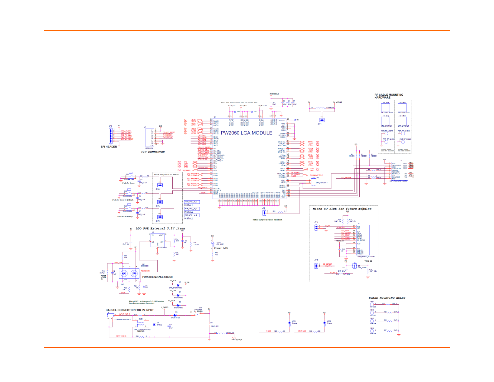
Evaluation Board Schematic
Figure 2-2 Evaluation Board Schematic for Part 1 of 4
PremierWave® 2050 Enterprise Wi-Fi® IoT Module Evaluation Kit User Guide 16
Page 17
2: Evaluation Kit
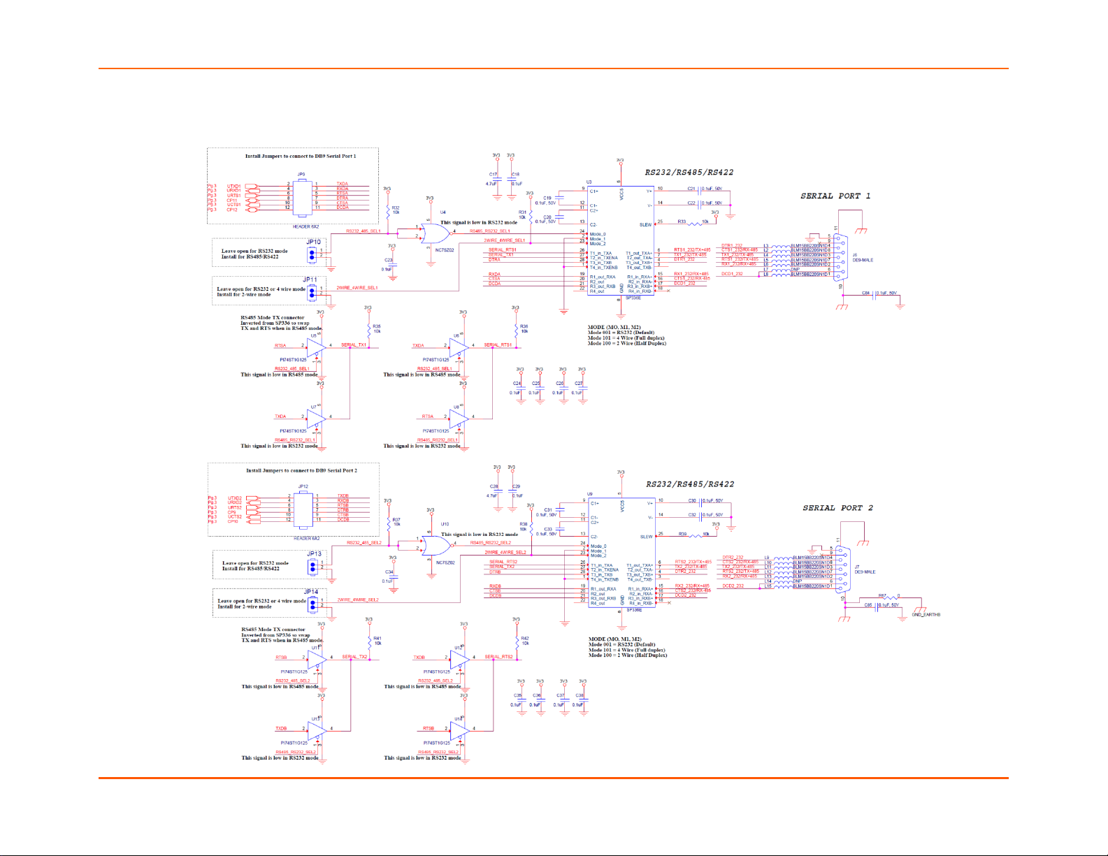
Figure 2-3 Evaluation Board Schematic Part 2 of 4
PremierWave® 2050 Enterprise Wi-Fi® IoT Module Evaluation Kit User Guide 17
Page 18
2: Evaluation Kit
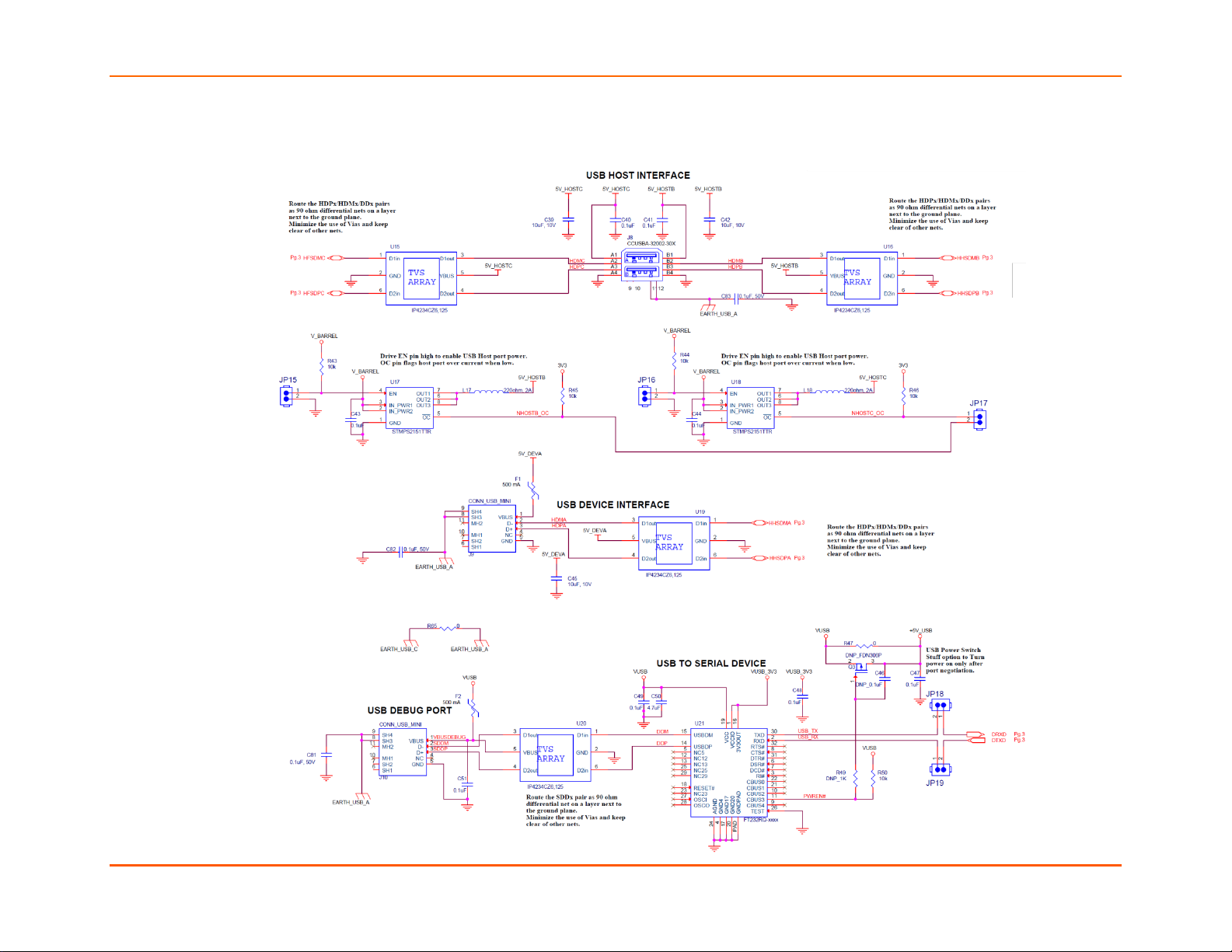
Figure 2-4 Evaluation Board Schematic Part 3 of 4
PremierWave® 2050 Enterprise Wi-Fi® IoT Module Evaluation Kit User Guide 18
Page 19

2: Evaluation Kit
Figure 2-5 Evaluation Board Schematic Part 4 of 4
PremierWave® 2050 Enterprise Wi-Fi® IoT Module Evaluation Kit User Guide 19
Page 20

Mouser Electronics
Authorized Distributor
Click to View Pricing, Inventory, Delivery & Lifecycle Information:
Lantronix:
PW205010002K PW205020002K
 Loading...