

Page 1

Micro125
Embedded Device Server
Integration Guide
Part Number 900-587
Revision C December 2015
Page 2

Copyright and Trademark
Date
Rev.
Comments
March 2011
A
Initial Release
April 2011
B
Updated serial interface information.
C
Updated reset input tolerance information.
© 2015 Lantronix, Inc. All rights reserved. No part of the contents of this publication may
be transmitted or reproduced in any form or by any means without the written permission
of Lantronix. Printed in the United States of America.
Lantronix is a registered trademark of Lantronix, Inc. in the United States and other
countries. DeviceInstaller is a trademark of Lantronix, Inc.
Patented: patents.lantronix.com
Ethernet is a trademark of XEROX Corporation. UNIX is a registered trademark of The
Open Group. Windows is a trademark of Microsoft Corporation.
Contacts
Lantronix Corporate Headquarters
7535 Irvine Center Drive
Suite 100
Irvine, CA 92618, USA
Toll Free: 800-526-8766
Phone: 949-453-3990
Fax: 949-453-3995
Technical Support
Online: www.lantronix.com/support
Sales Offices
For a current list of our domestic and international sales offices go to the Lantronix web
site at www.lantronix.com/about/contact
Disclaimer and Revisions
; Additional patents pending.
.
Operation of this equipment in a residential area is likely to cause interference, in which
case the user, at his or her own expense, will be required to take whatever measures
may be required to correct the interference.
Changes or modifications to this device not explicitly approved by Lantronix will void the
user’s authority to operate this device.
The information in this guide may change without notice. The manufacturer assumes no
responsibility for any errors which may appear in this guide.
December 2015
Micro125 Embedded Device Server Integration Guide 2
Page 3

Contents
Copyright and Trademark ............................................................................................. 2
Contacts ........................................................................................................................ 2
Disclaimer and Revisions .............................................................................................. 2
List of Figures ................................................................................................................ 4
List of Tables ................................................................................................................. 4
1: Introduction 5
Embedded Integration Kits ............................................................................................ 5
About the Integration Guide .......................................................................................... 5
Chapter Summaries ...................................................................................................... 6
Additional Documentation ............................................................................................. 6
2: Description and Specifications 7
The Micro125 ................................................................................................................ 7
Layout and Dimensions ................................................................................................ 8
Connectors .................................................................................................................... 9
Ethernet Interface ........................................................................................................ 10
Status LEDs ................................................................................................................ 11
Product Information Label ........................................................................................... 12
Technical Specifications ............................................................................................. 12
3: Integration Guidelines 14
Power Supply .............................................................................................................. 14
Network Connector ..................................................................................................... 14
Virtual Ground ............................................................................................................. 15
Serial Signals .............................................................................................................. 15
Additional Emission Improvements ............................................................................. 15
4: Test Bed 16
Board Layout ............................................................................................................... 16
Test Bed Connectors .................................................................................................. 17
A: Compliance and Warranty Information 18
Compliance Information .............................................................................................. 18
RoHS Notice ......................................................................................................... 19
Warranty ...................................................................................................................... 19
Micro125 Embedded Device Server Integration Guide 3
Page 4

List of Figures
Figure 2-1 Micro125 Board Layout ............................................................................................................... 8
Figure 2-2 Micro125 Top View ...................................................................................................................... 8
Figure 2-3 Micro125 Connector End View .................................................................................................... 9
Figure 2-4 Micro125 Connectors .................................................................................................................. 9
Figure 2-5 RJ45 Ethernet Connector .......................................................................................................... 10
Figure 2-6 Micro125 Status LEDs ............................................................................................................... 11
Figure 2-7 Product Label ............................................................................................................................. 12
Figure 3-1 Multi-Layer Board Strategy ........................................................................................................ 15
Figure 4-1 Carrier Board ............................................................................................................................. 16
Figure 4-2 Pin Configurations ..................................................................................................................... 17
List of Tables
Table 1-1 Micro125 Part Num ber s ................................................................................................................ 5
Table 2-1 Micro125 Connector Pinouts ...................................................................................................... 10
Table 2-2 Micro125 Status LEDs ................................................................................................................ 11
Table 2-3 Micro125 Technical Specifications ............................................................................................. 12
Table 4-1 Micro125 Test Bed Connectors .................................................................................................. 17
Micro125 Embedded Device Server Integration Guide 4
Page 5

Part Number
Description
MO00AA003-01R
Micro125, No RJ45 connector, No LEDS, with TTL pin header, RoHS
MO00AA0E3-01R
AES Encrypted Micro125, No RJ45 connector, No LEDS, with TTL pin
header, RoHS
MO11AA003-01R
Micro125 with RJ45 connec tor, LEDS, with TTL pin header, RoHS
MO11AA0E3-01R
AES Encrypted Micro125 with RJ45 connector, LEDS, with TTL pin
header, RoHS
MO22AA003-01R
Micro125, Pin header for Ethernet, Pin header for LED connection,
with TTL pin header, RoHS
MO22AA0E3-01R
AES Encrypted Micro125, Pin header for Ethernet, Pin header for LED
connection, with TTL pin header, RoHS
1: Introduction
Embedded Integration Kits
The Embedded Integration Kit provides a simple method of evaluating our Micro125
embedded device server. This product allows software engineers to test our device
servers with their products prior to the hardware development of those products.
Each kit contains an embedded device server, board carrier unit, and all the connectors
needed to interface our product with your serial device.
The Embedded Integration Kits include the following:
An embedded device server: Micro125
Board carrier unit with serial (DB9) interface. (Some carriers also have RJ45
Ethernet)
Power supply
CAT5 Ethernet cable, RJ45M/M, 10-foot
10-foot serial cable, DB9 (cable end depends on kit)
DB9 to DB-25 converter
About the Integration Guide
This guide provides the information needed to install and test the Micro125 embedded
device server on the Evaluation Board. The intended audience is the engineer
responsible for integrating the device server into your product.
This document covers the following Micro125 Device Server part numbers:
Table 1-1 Micro125 Part Numbers
Micro125 Embedded Device Server Integration Guide 5
Page 6

Chapter Summaries
Chapter
Description
2: Description and
Specifications
Describes and provides information about the Micro125
device server.
3: Integration Guidelines
Provides general guidelines to help you integrate the
Micro125 board into your design.
4: Test Bed
Describes the board layout and connectors of the test bed.
A: Compliance and Warranty
Information
Describes the compliance and warranty information.
Document
Description
Micro125 User Guide
Provides information needed to configure, use, and update
the Micro125 firmware.
Device Installer User
Guide
Provides instructions on using the Windows-based uti lity
used to configure Lantronix embedded device servers.
Com Port Redirector
User Guide
Provides information on using the Window s-ba sed uti lity to
create a virtual com port.
The remaining chapters in this guide include:
Additional Docume ntation
1: Introduction
Visit the Lantronix website at www.lantronix.com/support/documentation for the latest
documentation and the following additional documentation.
Micro125 Embedded Device Server Integration Guide 6
Page 7

2: Description and Specifications
The Micro125 embedded device server provides an integrated solution to add proven
Ethernet connectivity to an existing design quickly and economically, and with a high
level of flexibility.
The Micro125
The Micro125 contains Lantronix’s own DSTni controller, with 256 Kbytes of SRAM,
16 Kbytes of boot ROM, and an integrated 10/1 00 PH Y.
The Micro125 also contains the following:
RJ45 (10/100Base-T) ethernet network interface
TTL level (asynchronous) serial interface
Two serial ports
Accepts 5 VDC regulated Input power
Flash ROM for easy software upgrades
Serial channel status, Ethernet link status, and diagnostic LEDs
The Micro125 requires 5 VDC ±5% at ~ 210mA power and is designed to operate in an
extended temperature range (see Technical Specifications on page Error! Bookmark
not defined.).
Micro125 Embedded Device Server Integration Guide 7
Page 8

Layout and Dimensi ons
The Micro125 integrates into products quickly and easily. Serial interfacing is
accomplished via a TTL connector, and for Ethernet access, an optional RJ45
(10/100Base-T) connector is available. The orientation of its interface pins can be
specified to fit your product. It requires 5 volts DC of regulated power with maximum
current of 210mA.
2: Description and Specifications
Figure 2-1 Micro125 Board Layout
The following drawing is a top view of the Micro125.
Figure 2-2 Micro125 Top View
Micro125 Embedded Device Server Integration Guide 8
Page 9

The following drawing shows the connector end view of the board with the LEDs and
CON1
(TTL)
111
212
CON2
(RJ45)
CON3
12
34
12
78
S1
CON4
(LEDs)
RJ45 connector installed. The drawing on the right shows the dimensions for CON1 (DIL
2 x 6).
Connectors
2: Description and Specifications
Figure 2-3 Micro125 Connector End View
The Micro125 has four connectors: a TTL serial port (CON1), a 10/100Base-T RJ45
Connector (CON2), and/or pins instead of the RJ45 connector (CON3) and LEDs
(CON4).
Figure 2-4 Micro125 Connectors
The Micro125 that comes with the integration kit is factory configured. When ordering the
Micro125 for production use, each connector can be specified as follows:
Pins on/off the board and top/bottom (Figure 2-2 and Figure 2-3)
LEDs on/off the board
RJ45 on/off the board
Contact Lantronix for information about ordering the Micro125 with customized connector
configurations.
The Embedded Integration Kit (part number Micro-Kit) includes the Micro125 embedded
Micro125 Embedded Device Server Integration Guide 9
device server. Refer to the following table for a listing of its pinouts.
Page 10

2: Description and Specifications
CON1
(DIL 2 x 6 Pins)
CON2
(RJ45) Connector
CON3 (2 x 2 Pins
CON4 (2 x 4 Pins in place
Pin
Signal
Pin
Signal
Pin
Signal
Pin
Signal
1
+5VDC
1
Tx+ 1 Tx+ 1 +3.3 VDC
2
GND
2
Tx- 2 Tx- 2 +3.3 VDC
3
RxA (input)
3
Rx+ 3 Rx+ 3 LED3
(Diagnostics)1
4
TxA (output)
4
None 2
5)
4
Rx- 4 LED1 (Channel 1) 1
5
RTSA (output)
5
None (tied
to Pin 4)
5
+3.3 VDC
6
DTRA (output)
6
Rx-
6
+3.3 VDC
7
CTSA (input)
7
None (tied
to Pin 8)
7
LED2 (Channel 2) 1
8
DCDA (input)
8
None (tied
to Pin 7)
8
LED4 (Link) 1
9
Reserved
10
RESET (pull
tolerant.
11
RxB (input)
12
TxB (output)
1
Current limiting resistor on board is 220 Ohms.
A = Port (Channel) 1 B = Port (Channel) 2
1 8
1 - TX+
2 - TX3 - RX+
6 - RX-
Table 2-1 Micro125 Connector Pinouts
TTL Serial Port
low to reset)
Note: the reset
input is 3.3V
10/100Base-T
(tied to Pin
in place of RJ45)
of LEDs)
2
150 Ohms exist between the Pin 4/5 node and the Pin 7/8 node.
Ethernet Interf ace
The standard Micro125 ships with an RJ45 10/100Base-T Ethernet connector (CON2). At
the time of ordering, you can specify whether to include this RJ45 connector. You can
use CON3 as an alternative.
Figure 2-5 RJ45 Ethernet Connector
Micro125 Embedded Device Server Integration Guide 10
Page 11
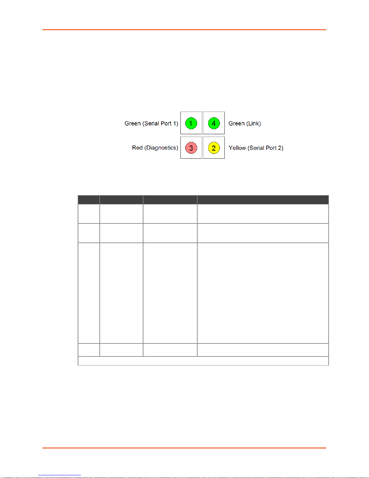
Status LEDs
LED
Description
Location
LED Functions
1
SerialPort
Status
CON 4, Pin 4
Lights solid green to indicate Channel 1 is idle.
the network and active.
2
SerialPort
Status
CON 4, Pin 7
Lights solid yellow to indicate Channel 2 is idle.
the network and active.
3
Diagnostics
CON 4, Pin 3
Blinks or lights solid red in combination with the
4
Network Link
Status
CON 4, Pin 8
Lights solid green to indicate network port is
connected to the network.
*non-fatal error
The Micro125 carrier board has four status LEDs: serial port (Channel) 1 status, serial
port (Channel) 2 status, diagnostics, and network link status. See the following table for a
complete description of LED functions and pinout locations.
2: Description and Specifications
Figure 2-6 Micro125 Status LEDs
Table 2-2 Micro125 Status LEDs
(Channel) 1
(Channel) 2
Blinks green to indicate Channel 1 is connected to
Blinks yellow to indicate Channel 2 is connected to
green (Channel 1) LED to indicate diagnostics and
error detection.
Red solid, green (Channel 1) blinking:
1x: EPROM checksum error
2x: RAM error
3x: Network controller error
4x: EEPROM checksum error
5x: Duplicated IP address on the network*
6x: Software does not match hardware*
Red blinking, green (Channel 1) blinking:
4x: Faulty network connection*
5x: No DHCP response received*
Micro125 Embedded Device Server Integration Guide 11
Page 12

Product Informa ti on Label
Category
Description
CPU, Memory
Lantronix DSTni-EX 186 CPU, 256-Kbyte zero wait state SRAM, 512-Kbyte flash,
16-Kbyte boot ROM
Firmware
Upgradeable via TFTP and serial port
Serial Interface
2 TTL serial interfaces (Asynchronous).
Note: the reset input is 3.3V tolerant.
Serial Line Formats
Data bits: 7 or 8
Parity: odd, even, none
Board Dimensions
Height: 1.575in (40.00 mm)
Width: 1.935in (49.15 mm) (See Drawing)
Weight
0.7 ounces
Modem Control
DTR, RTS, CTS, DCD
Flow Control
XON/XOFF (software), CTS/RTS (hardware), None
Network Interface
RJ45 (10/100Base-T) Ethernet
Compatibility
Ethernet: Version 2.0/IEEE 802.3
Power Requirements
5VDC (±5%) regulated @ 210mA
Protocols Supported
ARP, UDP/IP, TCP/IP, Telnet, ICMP, SNMP, DHCP, BOOTP, TFTP, Auto IP, and
HTTP
LEDs
Channel 1 (solid Green = idle, blink = active)
Network Link (Green)
Management
Internal web server, SNMP (read only)
Serial login, Telnet login
Security
Password protection, opti onal Rijndael 256-bit encryption
Internal Web Server
Serves static Web pages and Java applets
Storage capacity: 384 Kbytes
Temperature
Standard Temperature Operating Range: 0° to 70°C (32° to 158°F)
Revision Number
MAC Address
Part Number
Manufacturing Date
The product information label contains important information about your specific unit,
such as its product number, revision number, manufacturing date and mac address.
2: Description and Specifications
Figure 2-7 Product Label
Technical Specifications
5V-level input signals. 3.3 V-level out put sig nal s. Through-hole plated pins, DIL.
Stop bits: 1 or 2
Table 2-3 Micro125 Technical Specifications
Channel 2 (solid Yellow = idle, blink = active)
Diagnostics (Red, in combination with Channel 1)
Micro125 Embedded Device Server Integration Guide 12
Page 13

2: Description and Specifications
Category
Description
Storage Temperature Range: -40° to 85°C (-40° to 185°F)
Emissions
FCC Part 15 Subpart B
EN 61000-6-3: 2001
Immunity
EN 55024: 1998 +A1: 2001 +A2: 2003
EN 61000-6-2: 2001
Compliance
Industry Canada ICES-003 Issue 4 February 2004
CISPR 22: 2005 Information Technology Equipment
VCCI V-3/2010.04
AS/NZS CISPR 22: 2009
EN 55022: 2006 + A1:2007
EN 61000-3-2: 2006
EN 61000-3-3: 2008
EN 61000-4-2: 1995 + A2: 2001
EN 61000-4-3: 2006 + A1: 2008
EN 61000-4-4: 2004
EN 61000-4-5: 2006
EN 61000-4-6: 2007
EN 61000-4-8: 1994 + A1: 2001
EN 61000-4-11: 2004
Micro125 Embedded Device Server Integration Guide 13
Page 14

3: Integration Guidelines
This chapter provides general guidelines to integrate the Micro125 board into your
design, and help you reach the necessary standards for your applications.
Power Supply
The Micro125 runs at 5 VDC nominal, ±5%. The current consumption varies for the
different products and depends upon their operating conditions. Refer to the current
requirements listed in the product specification to design an appropriate power supply.
To maintain the necessary voltage, provide ground to the appropriate connector header
with a low inductance and low DC resistance path. The best solution is a solid ground
plane.
Place a de-coupling capacitor pair as close as possible to the connector headers of the
board’s power supply. We recommend a ceramic (X7R material or equivalent, value
μF to 0.1 μF) and a low DC resistance (electrolytic or tantalum value
0.022
μF to 100 μF) capacitor.
10
Network Connector
If you use the on-board RJ45 connector, we suggest that you provide ground level to the
plated mounting hole near the RJ45. That shielded cable will be tied to the appropriate
level, however the virtual ground is also provided there.
If you want to add an RJ45 connector, we recommend that it be at least partially shielded
in case it will be used in a noisy environment. (Please refer to the product-specific
section.)
Take care regarding the trace length and routing for the two differential pairs, TX and RX.
Neither of them may cross or run in parallel with any digital signal nor run through a
digital ground or power plane. The trace length inside of the unit running from the device
server to the RJ45 should be as short as possible. The trace length may have an impact
on signal quality (link length), especially if internal ambient noise is a factor.
If trace length cannot be shortened, or the internal noise frequencies are hitting the
carrier frequency or the multiples of these (depending on the product and operating mode
either 10MHz or 100MHz and up to the 11th overtone), we suggest a different strategy.
Use a multi-layer board and a separated shield layer on the solder and assembly sides of
the board, which are routed in the inner layers. (Refer to the following figure.) These
shield layers can either be connected to the RJ45s shield or to a virtual ground signal
provided by the device server.
Micro125 Embedded Device Server Integration Guide 14
Page 15

3: Integration Guidelines
Figure 3-1 Multi-Layer Board Strategy
Virtual Ground
The device server provides a virtual ground at a (plated) mounting hole. It is a ground
imitation. It uses the tap of two capacitors (ceramic 0.1 μF) conducted symmetrically to
ground and VCC. In the absence of a solid ground (earth), this virtual ground can be
used for shielding or balancing metal parts of the case.
Serial Signals
Device server TTL-level serial input and output signals are protected by 220-Ohm
resistors. These resistors provide a simple output shortage protection for infinite duration
(by limiting the current). They also reduce conducted interferences at higher frequencies
to the base board.
Additional Emission Improvements
Depending on the voltage regulator used and bas e bo ar d design, the pow er supp l y cord
may sometimes emit conducted interferences. If the voltage level there is low, common
mode chokes are the appropriate barrier to avoid these frequencies being emitted via the
power cord as an antenna.
Common mode chokes help pass the conducted emission requirements of the EN55022
for frequencies below 30 MHz. Metal cases or partial metal shielding inside the unit can
also help to reduce emission levels so that even more stringent standards can be
passed.
Micro125 Embedded Device Server Integration Guide 15
Page 16
4: Test Bed
The Micro125 Embedded Integration Kit includes a test bed (carrier board) that provides
serial connections to the device server. The Micro125 device server provides a network
10/100Base-T RJ45. The test bed contains a power LED, TTL to RS-232 and RS-232 to
TTL conversion hardware, a 3-pin connector for the second serial port, and mounting
hardware for the Micro125.
The test bed allows software engineers to immediately begin developing and testing
software applications for the device server, rather than delaying the process until the
hardware interface for their product is complete.
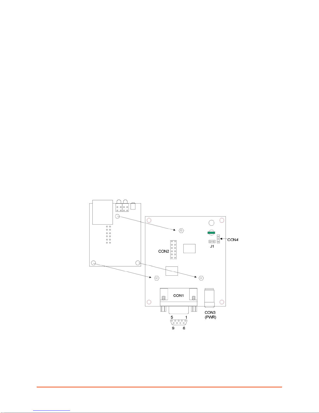
Board Layout
Install the Micro125 onto the carrier board as shown below.
Figure 4-1 Carrier Board
Micro125 Embedded Device Server Integration Guide 16
Page 17

Test Bed Connectors
CON1 Serial Port
(Channel) 1a
CON2 TTL Interface
CON4 Serial Port
(Channel) 2b
Pin
Signal
Pin
Signal
Pin
Signal
1
DTRA (output)
1
+5 VDC
1
TxB (output)
2
TxA (output)
2
GND
2
RxB (input)
3
RxA (input)
3
TxA (output)
3
GND
4
DCDA (input)
4
RxA (input)
5
GND
5
CTSA (input)
6
None
6
DCDA (input)
7
CTSA (input)
7
RTSA (output)
8
RTSA (output)
8
DTRA (output)
9
None
9
None
10
None
11
TxB (output)
12
RxB (input)
a. CON1 Serial Port (Channel) 1 is also designated as A.
b. CON4 Serial Port (Channel) 2 is also designated as B.
A: Compliance and Warranty Information
Figure 4-2 Pin Configurations
The Micro125 test bed has four connectors: CON1 (Serial Port 1 or Channel 1), CON2
(TTL Interface), CON4 (Serial Port 2 or Channel 2), and CON3, which is a 5VDC power
supply connector.
This RS-232 level serial interface is implemented with a DB9F connector. The Micro125
converts the RS-232 serial transmit and receive data of this interface to Ethernet protocol
transmit and receive data. The DB9 connector was selected for compatibility with most
PC serial interface ports using a straight through cable.
Table 4-1 Micro125 Test Bed Connectors
Micro125 Embedded Device Server Integration Guide 17
Page 18

A: Compliance and Warranty Information
Compliance Inf ormation
(According to ISO/IEC Guide 22 and EN 45014)
Manufacturer’s Name & Address
Lantronix 167 Technology Drive, Irvine, CA 92618 USA
Declares that the following product:
Product Name Model: Micro125 Embedded Device Server
Conforms to the following standards or other normative documents:
Emissions
FCC Part 15 Subpart B, Class B
Industry Canada ICES-003 Issue 4 February 2004
CISPR 22: 2005 Information Technolog y Equipment
VCCI V-3/2010.04
AS/NZS CISPR 22: 2009
EN 55022: 2006 + A1:2007
EN 61000-3-2: 2006
EN 61000-3-3: 2008
EN 61000-6-3: 2001
Immunity
EN 55024: 1998 +A1: 2001 +A2: 2003
EN 61000-4-2: 1995 + A2: 2001
EN 61000-4-3: 2006 + A1: 2008
EN 61000-4-4: 2004
EN 61000-4-5: 2006
EN 61000-4-6: 2007
EN 61000-4-8: 1994 + A1: 2001
EN 61000-4-11: 2004
EN 61000-6-2: 2001
Micro125 Embedded Device Server Integration Guide 18
Page 19

A: Compliance and Warranty Information
• Lead (Pb)
• Mercury (Hg)
• Polybrominated biphenyls (PBB)
• Cadmium (Cd)
• Hexavalent Chromium (Cr (VI))
• Polybrominated dip he n yl eth ers (PB D E )
Product Family Name
Toxic or hazardous Substances and Elements
Lead
Mercury
Cadmium
Hexavalent
(Cr (VI))
Polybrominated
Polybrominated diphenyl
UDS1100 and 2100
0 0 0 0 0
0
EDS 0 0 0 0 0 0
MSS100 0 0 0 0 0 0
IntelliBox 0 0 0 0 0 0
XPress DR & XPress-DR+
0 0 0 0 0
0
SecureBox 1101 & 2101
0 0 0 0 0
0
WiBox 0 0 0 0 0 0
UBox 0 0 0 0 0 0
MatchPort 0 0 0 0 0 0
SLC 0 0 0 0 0 0
XPort 0 0 0 0 0 0
WiPort 0 0 0 0 0 0
SLB 0 0 0 0 0 0
SLP 0 0 0 0 0 0
SCS 0 0 0 0 0 0
SLS 0 0 0 0 0 0
DSC 0 0 0 0 0 0
PremierWave
0 0 0 0 0
0
Micro125 0 0 0 0 0 0
RoHS Notice
All Lantronix products in the following families are China RoHS-compliant and free of the following hazardous substances and
elements:
(Pb)
O: toxic or hazardous substance contained in all of the homogeneous materials for this part is below the limit requirement in SJ/T11363-2006.
X: toxic or hazardous substance contained in at least one of the homogeneous materials used for this part is above the limit requirement in SJ/T11363-2006.
(Hg)
(Cd)
Chromium
biphenyls (PBB)
ethers (PBDE)
Manufacturer’s Contact
Lantronix
7535 Irvine Center Drive
Suite 100
Irvine, CA 92618, USA
Toll Free: 800-526-8766
Phone: 949-453-3990
Fax: 949-453-3995
Warranty
For details on the Lantronix warranty replacement policy, please go to our Web site at
www.lantronix.com/support/warranty
Micro125 Embedded Device Server Integration Guide 19
.
 Loading...