

Page 1

ManageLinx
User Guide
Part Number 900-515
Revision D November 2008
Page 2

Copyright & Trademark
© 2008, Lantronix. All rights reserved. No part of the contents of this book may be
transmitted or reproduced in any form or by any means without the written permission of
Lantronix. Printed in the United States of America.
Contacts
Lantronix Corporate Headquarters
15353 Barranca Parkway
Irvine, CA 92618, USA
Phone: 949-453-3990
Fax: 949-453-3995
Technical Support
Online:
Phone (US only):
(949) 422-7040
(949) 453-7198
Sales Offices
For a current list of our domestic and international sales offices, go to the Lantronix web
site at
www.lantronix.com/support
www.lantronix.com/about/contact .
Disclaimer
The information in this guide may change without notice. The manufacturer assumes no
responsibility for any errors that may appear in this guide.
Revision History
Date Rev. Comments
April 2008 A Initial Document
May 2008 B Updated technical descriptions.
June 2008 C Updated technical descriptions.
November 2008 D
Added new features Licensing, Dynamic Ports,
Tunneling
ManageLinx User Guide 2
Page 3

Contents
1: Using This Guide 6
Purpose and Audience..................................................................................................6
Summary of Chapters...................................................................................................6
Additional Documentation.............................................................................................7
2: ManageLinx Overview 8
Configuration Sequence ...............................................................................................9
Product Information Label.............................................................................................9
Addresses and Port Numbers.....................................................................................10
Hardware Address_______________________________________________ 10
IPv4 Address___________________________________________________ 10
VIP Address____________________________________________________ 10
Technical Specifications .............................................................................................10
3: DSM Installation 12
Buttons and Status LEDs............................................................................................12
Installing the DSM.......................................................................................................13
DSM Power Requirements ________________________________________ 13
Configuring Network Settings .....................................................................................14
4: DSC Installation 15
Installing the DSC .......................................................................................................15
LEDs ...........................................................................................................................18
Back _________________________________________________________ 18
Front _________________________________________________________ 18
5: Web Manager Guide 20
Accessing the Web Manager......................................................................................20
Web Manager User Interface Components................................................................21
Web Manager Icons....................................................................................................21
Web Manager Maps....................................................................................................22
Web Manager Filters...................................................................................................22
Web Manager Elements .............................................................................................23
Viewing All Elements_____________________________________________ 23
Exiting the Web Manager............................................................................................23
ManageLinx User Guide 3
Page 4

Contents
6: Network Settings 24
Add a DSC..................................................................................................................24
Configuring a Device Services Controller _____________________________ 25
Configuring Network Settings .....................................................................................25
Auto Configuration_______________________________________________ 25
Manual Configuration ____________________________________________ 26
Creating and uploading a DSC Bootstrap File............................................................26
Adding Other Elements...............................................................................................27
Adding a Device or Device Server___________________________________ 27
7: Licensing 29
Purchase a License.....................................................................................................29
Add License File..........................................................................................................29
Display License Usage ...............................................................................................30
Save Licenses to PC...................................................................................................30
8: Monitoring Devices 31
Viewing Device Settings .............................................................................................31
Viewing Conduit Status...............................................................................................32
9: Route Configuration 33
DSM Ports...................................................................................................................33
Configure Ports _________________________________________________ 33
Display Ports ___________________________________________________ 34
Configuring Elements..................................................................................................35
Device Profile: General Tab _______________________________________ 35
Device Profile: Network Tab _______________________________________ 36
Adding a DSC .............................................................................................................37
Deleting an Element....................................................................................................37
10: Maps and Category Filters 38
Maps ...........................................................................................................................38
Adding a Map __________________________________________________ 38
Editing or Deleting a Map _________________________________________ 39
Filters ..........................................................................................................................39
Adding a Category Filter __________________________________________ 40
Editing or Deleting a Category Filter _________________________________ 40
Using Maps and Category Filters................................................................................40
System Settings: Category Filters Tab _______________________________ 41
System Settings: Map Filters Tab ___________________________________ 42
ManageLinx User Guide 4
Page 5

Contents
Hiding and Showing Elements on the Dock____________________________ 43
11: VIP Routes 45
Virtual IP Routes.........................................................................................................45
TCP Tunneling__________________________________________________ 45
UDP Tunneling:_________________________________________________ 47
UDP VIP Route Types................................................................................................47
UDP Uni-Directional Routing_______________________________________ 48
Bi-directional Manual Reverse Mapping ______________________________ 49
Bi-directional Automatic Reverse Mapping ____________________________ 51
Add a VIP to the Pool..................................................................................................52
Deleting a Route .........................................................................................................52
Deleting a VIP.............................................................................................................53
12: DSM Administration 54
Manage Global Settings..............................................................................................54
Changing the ManageLinx Password.........................................................................54
System Logging ..........................................................................................................55
Backing up & Restoring System Settings...................................................................56
Rebooting and Shutting Down the DSM.....................................................................57
Viewing System Information .......................................................................................58
Lantronix Contact Information.....................................................................................59
13: Technical Support and Warranty 60
Technical Support.......................................................................................................60
A: DSC Compliances 61
B: Warranty 64
Index 65
ManageLinx User Guide 5
Page 6

1: Using This Guide
Purpose and Audience
This guide provides the information needed to install, configure, and update the Device
Services Manager, the Device Services Controller (DSC), and how to create virtual
routes between devices on different networks.
Summary of Chapters
Chapter Description
1: Using This Guide
2: ManageLinx Overview
3: DSM Installation
4: DSC Installation
5: Web Manager Guide
6: Network Settings
7: Licensing
8: Monitoring Devices
9: Route Configuration
10:Maps and Category Filters
11:VIP Routes
12: DSM Administration
Main features of the product and the protocols it supports. Includes
technical specifications.
Installing the DSM and configuring network settings.
Installing the DSC and configuring network settings.
Accessing the DSM Web Manager and using it to configure
settings.
Configuring the DSM and DSC using Web Manager.
Licensing information.
Viewing an element configuration and status.
Configuring and editing elements.
Working with maps and category filters.
Adding and configuring Virtual IP (VIP) addresses and routes.
Changing passwords, system logging, and modifying general
system settings.
13:Technical Support and
Warranty
ManageLinx User Guide 6
Common problems and error messages and how to contact
Lantronix Technical Support.
Page 7

Additional Documentation
The following guides are available on the CD-ROM the Lantronix Web site:
www.lantronix.com.
1: Using This Guide
Device Services Controller
Quick Start Guide
Device Services Manager Quick
Start Guide
Brief overview on installing the DSC.
Brief overview on installing and configuring
the DSM.
ManageLinx User Guide 7
Page 8

2: ManageLinx Overview
ManageLinx solves the access-through-firewall problem and utilizes existing network
infrastructure to create a virtual device network (VDN). The VDN provides direct access
to only authorized equipment, behind firewalls, from anywhere via the net.
Our VDN technology enables you to create dedicated TCP/IP connections between any
two devices, using easily deployed hardware appliances. There is no client software to
install. No changes are required to network software or applications at either end of the
connection. ManageLinx is a secure and totally transparent remote access solution.
The VDN hardware consists of a publicly accessible Device Services Manager (DSM)
and individual Device Services Controller (DSC) appliances in multiple locations.
Together, these two components enable you to set up and manage individual Virtual IP
(VIP) addresses and routes.
2: ManageLinx Overview
DSM
Public
Network
DSC
Host Controller
DSC
Device Controller
The Device Services Controller (DSC) appliances reside on remote and local networks
and mediate communications onto the LANs. In device controller mode, a DSC provides
simple access as well as end-point encryption for all traffic. To provide secure end-toend communications, a DSC sits on the LAN at each service center location. Operating
in host controller mode, a DSC provides a secure, scalable entry point to the ManageLinx
VDN system. Once enabled, the host or device controllers provide encrypted
communications through the firewall.
The Device Services Manager serves as a central management station and proxy
connection point for participating DSCs. The publicly addressable Device Services
Manager offers a complete Web 2.0-based management system for all VDN system
ManageLinx User Guide 8
Page 9

2: ManageLinx Overview
configuration and control. You can configure individual devices, set up automated device
discovery on remote networks, perform automated monitoring, and enable secure access
to any device visible to a participating Device Services Controller.
For an outside device to contact devices on private networks, there has to be a DSC on
the local segment of both devices and a DSM available to the DSCs. Alternatively, the
DSC can contact the DSM when an authorized local device requests communication with
another device using one of the DSC’s configured VIP (proxy) addresses.
The DSM acts as a publicly accessible call center server. It grants access for isolated
device communication through a secure encrypted tunnel by means of the DSC on the
local segment of the devices behind a firewall. It is also responsible for remote
management, maintenance, configuration and registration of detected DSCs and device
servers on the network.
The DSC’s primary responsibility is to provide a secure and encrypted com m unication
path for isolated public internet devices to communicate with devices local to the DSC
through firewalls on a local private network. The DSC periodically polls the configured
parent DSM to retrieve registry information such as discovered device data, maintenance
reports, and configuration information.
The DSM completely manages the DSCs. You create and maintain configuration profiles
on the DSM. You transfer configuration data from the DSM to the DSC with a USB flash
drive (provided). Then you use the web-based WebManager interface for access,
configuration, and management of the DSCs and VPN.
Configuration Sequence
The overall configuration sequence is as follows:
1. Install and configure the DSM. See Chapter
2. Via the Web Manager interface, connect to the DSM and define and configure all
elements of your ManageLinx network. See page
3. Install and configure the DSCs. Use your PC and the Lantronix flash drive to copy a
bootstrap file from the DSM to each DSC. See Chapter
4. Configure specific communication routes. See Chapter
Product Information Label
The product information label on the underside of the unit contains the following
information about your specific unit:
Hardware address (also referred to as Ethernet o r MAC add ress)
Bar code
Serial number
3: DSM Installation.
14.
4: DSC Installation.
11: VIP Routes.
Product ID (name)
Product description
ManageLinx User Guide 9
Page 10

Addresses and Port Numbers
Hardware Address
The hardware address is also referred to as the Ethernet address or MAC address. The
first three bytes of the Ethernet address are fixed and read 00-80-A3, identifying the unit
as a Lantronix product. The fourth, fifth, and sixth bytes are unique numbers assigned to
each unit.
00-80-A3-14-01-18 or 00:80:A3:14:01:18
IPv4 Address
Every device connected to an IP network must have a unique IP Address. This address
references the specific unit. IP addresses are always in “dot-quad” format as shown
below.
2: ManageLinx Overview
Sample Hardware Address
Sample IP Address
VIP Address
In addition to IP addresses, the In addition to the IP addresses assigned to the DSM and
DSCs, the DSM also allows the user to configure virtual IP addresses (VIPs) on the
DSCs. These VIP addresses allow specified devices to communicate securely and
invisibly across networks and through firewalls without visibility, access, or intrusion to or
from any other devices. VIP addresses are also in “dot-quad” format.
Technical Specifications
Hardware
Operating System
Power
Requirements
Dimensions
172.18.212.11
Table 2-1. DSM Specifications
Processor: Intel® Pentium® 4, 3.0 GHz
RAM: 512 MB
Hard Disk: 160 GB
Ethernet: Two (2) 10/100/1000Base-T (RJ45)
Console: RS-232 (DB9M DTE)
USB: Four (4); front (2), rear(2)
Linux
100-240 VAC, 50 to 60 Hz, 250W
(1.7” (H) x 16.7” (W) x 14” (D)
ManageLinx User Guide 10
Page 11

2: ManageLinx Overview
Environmental
Temperatures
Certifications
Hardware
Peripherals and
Connectors
Software and O/S
Power
Requirements
Dimensions
Environmental
Temperatures
Operating: 10°C to 35°C (50°F to 95°F)
Storage: -40°C to 70°C (-40°F to 158°F)
FCC, C/UL,TUV, CE
Table 2-2. DSC Specifications
Intel XScale IXP420 Processor @ 266 MHz
256MB SDRAM
32MB Flash
8kb EEPROM
1 x 10/100 Ethernet with PoE (RJ45)
1 x 10/100 Ethernet (RJ45)
2 x serial ports (DB9M DTE)
1 x USB 2.0 (type “A” connector)
Flash Button (Reserved for future use.)
3 x bicolor LEDs
Linux, 2.6 kernel with glibc-2.2.5 and uClib-0.9.27 libraries,
Lantronix VDN Software
9-30V DC (barrel connector)
330mA @ 12V
802.3af compliant PoE
7”(W) x 5”(D) x 1”(H)
Operating: 0°C - 55°C (32°F - 132°F)
Storage: -40°C - 70°C (-40° to 158°F)
ManageLinx User Guide 11
Page 12

3: DSM Installation
DSM Installation consists of mounting the DSM in a 19” rack and making network and
power connections.
You connect a VGA and keyboard, or laptop, configure network settings, then log in to
the DSM WebManager interface to complete the final setup and configuration steps.
To configure the initial network settings for the DSM, you connect to the unit with either a
VGA and keyboard connection or a serial connection to a laptop or other terminal.
If you choose to connect using the serial console (VGA and keyboa rd), your serial
connection should be configured as follows:
Baud Rate 115200
Data Bits 8
Parity None
Stop Bits 1
Flow Control None
3: DSM Installation
Buttons and Status LEDs
The DSM has two buttons and five LEDs on the front panel of the unit. The two buttons
are Power On/Off and Reset. The five LEDs signal information during boot-up and while
the DSM is running.
LED State Meaning
Power
Hard drive
Network Port 1
Network Port 2
Steady green Power is on.
Blinking yellow
Green Activity.
Green Activity.
Hard drive access
(typical PC LED).
ManageLinx User Guide 12
Page 13

LED State Meaning
System
Overheat/Fan
Failure
Installing the DSM
DSM Power Requirements
The DSM has a universal auto-switching AC power supply. The power supply accepts the
normal North American household power supply: AC input voltage between 100 and 240
VAC with a frequency of 50 or 60 Hz.
Steady yellow
WARNING:
If the alarm LED comes on, quickly shut
down the DSM and contact Lantronix
Technical Support at
www.lantronix.com/support.
Continued use of the DSM while the alarm
indicator is on may cause permanent
system damage to hardware and data
stored in the system.
3: DSM Installation
Unit is
overheated.
CAUTION:
Be careful not to block the air vents on the front and back of the unit. If you
mount the DSM in an enclosed rack, we recommend that the rack have
ventilation to provide adequate airflow through the unit.
Make sure you have the correct power supply available for the DSM, as described above.
Mount the unit in a 19-inch rack.
Connect to the network port labeled Ethernet 1 (Ethernet 2 is not currently used) using a
standard RJ45-terminated Category 5 cable.
Connect the power cord and apply power.
Wait approximately a minute and a half for the boot process to complete.
ManageLinx User Guide 13
Page 14

Configuring Network Settings
To configure the initial network settings for the DSM, you connect to the unit with either a
VGA and keyboard connection or a serial connection to a laptop or other terminal.
1. Connect your interface device to the unit. The command line interface appears.
3: DSM Installation
2. Log in using
menu appears.
sysadmin as the user name and PASS as the password. The following
Enter a Static IP Address:
1. Type 3 and press Enter. The STATIC MENU appears.
2. Type 2 and press Enter.
3. Enter the IP Address and press Enter.
4. Type 3 and press Enter.
5. Enter the Netmask in dot-quad format and press Enter.
6. To save, type 5 and press Enter.
7. To return to the main menu, type 1 and press Enter.
8. To configure the gateway, type 4 and press Enter.
9. Enter the Default Gateway address in dot-quad format and press Enter.
10. To save, type 5 and press Enter.
ManageLinx User Guide 14
Page 15

4: DSC Installation
Bootstrapping is the process of loading configuration settings and firmware upg rades to
the DSC. You insert a preloaded flash drive into the USB port and the DSC does the
rest. Bootstrapping is used for initial configuration, resetting factory settings, and
firmware upgrades.
Installing the DSC
You may use normal North American household current as the primary power supply.
You may use power over Ethernet (PoE), as primary or backup power supply.
Install the DSC.
4: DSC Installation
1. Determine the location for the DSC. It may be wall-mounted or placed on a desktop.
2. Connect an Ethernet cable to the RJ45 port labeled WAN. The DEVICES port is
reserved for future use.
3. If you are not using PoE, connect AC power to your unit using the power cord
provided.
4. Supply power to the DSC.
5. Wait for the DSC LED to glow a steady green indicating it has powered up and is
waiting for configuration.
6. Continue with Configuring the DSC—General Settings.
Configuring the DSC—General Settings
1. Open your internet browser (I.E. 6.0 or later) or (Firefox 2.0 or later).
2. Enter the IP address of the DSM.
3. Log in using sysadmin as the user name and PASS as the password.
ManageLinx User Guide 15
Page 16

4: DSC Installation
4. On the DSM Web Manager, click CONFIGURATION.
By default two DSCs are already shown on the map. You may skip the next two steps
unless you want to add more DSCs at this time.
5. On the command menu, click ADD DSC.
6. Click anywhere on the map. The DSC icon
appears in that location. And you
can drag it to any other location.
7. On the command menu, select CONFIGURE ELEMENT, then click a DSC icon. The
Configure Element page appears with the General tab selected by default.
8. Enter a Profile Name (required), Profile Description (optional), and click Save Profile.
9. Continue with Configuring IP Settings.
ManageLinx User Guide 16
Page 17

4: DSC Installation
Configuring IP Settings
Two options are available for configuring the DSC IP address settings. Auto-configure
and manual. Auto-configure is preferred and is the default. Auto-configure is
accomplished by the dynamic host control protocol (DHCP). Setting an IP address
manually sets a static IP address.
1. Click the Network tab.
2. Go to Option One.
(To configure using manual means, go to Option 2.)
Option 1: Auto-configure IP address
a. Click the Network tab.
b. Select Auto-configure IP Address.
c. Select DHCP: Enable.
d. Enter a DHCP hostname (optional).
e. Click Save Profile.
f. Continue with
Create a DSC Bootstrap file on page 18.
Option 2: Set a Static IP Address
a. Select Manual Configure IP address.
b. Enter an IP Address.
c. Enter a subnet mask.
d. Enter the default gateway.
e. Click Save Profile.
f. Continue with
Create a DSC Bootstrap file on page 18.
ManageLinx User Guide 17
Page 18

LEDs
4: DSC Installation
Create a DSC Bootstrap file.
This operation will create a bootstrap file on the USB flash drive that came with your
DSC. This flash drive is blank but is formatted and may be used later to reset or upgrade
the device firmware.
1. Click Create DSC Bootstrap.
2. Place the USB flash drive that came with your DSC in the DSC USB port. The DSC
automatically loads the bootstrap file to the USB. When the DSC LED stops flashing
the process is complete.
3. Remove the flash drive and store it in a safe place.
Back
Front
Normal Operation
On power-up, all the lights slowly turn red and then turn off. Once booted, the LEDs
behave as follows:
LED State Description
DSM
DSC
Activity
Off DSC not bootstrapped
Green Flashing
Green Solid DSC connected to DSM
Green Solid DSC is booted up
Not used at this time
DSC connecting or reconnecting
to DSM
ManageLinx User Guide 18
Page 19

4: DSC Installation
Bootstrapping
When you insert a USB flash drive containing the DSC bootstrap file (bootstrap.dna) into
the DSC USB port, the DSC LED does the following:
LED State Meaning
DSC
The bootstrap.dna file is only used once and is renamed to bootstrap.dna.old after a
successful load.
Green Flashing DSC accessing the USB flash drive.
Off DSC completed accessing the USB flash drive.
Amber Blinking 3
times
Red Missing bootstrap.dna or other configuration error.
USB flash drive removed.
ManageLinx User Guide 19
Page 20

5: Web Manager Guide
Accessing the Web Manager
1. Open a web browser (Mozilla Firefox 2.0 or later or Internet Explorer 6.0 or later).
2. Enter the DSM IP address. The ManageLinx login appears.
5: Web Manager Guide
3. Log in as system administrator (username
4. Click Submit.
5. The DSM Web Manager appears.
ManageLinx User Guide 20
sysadmin and password PASS).
Page 21
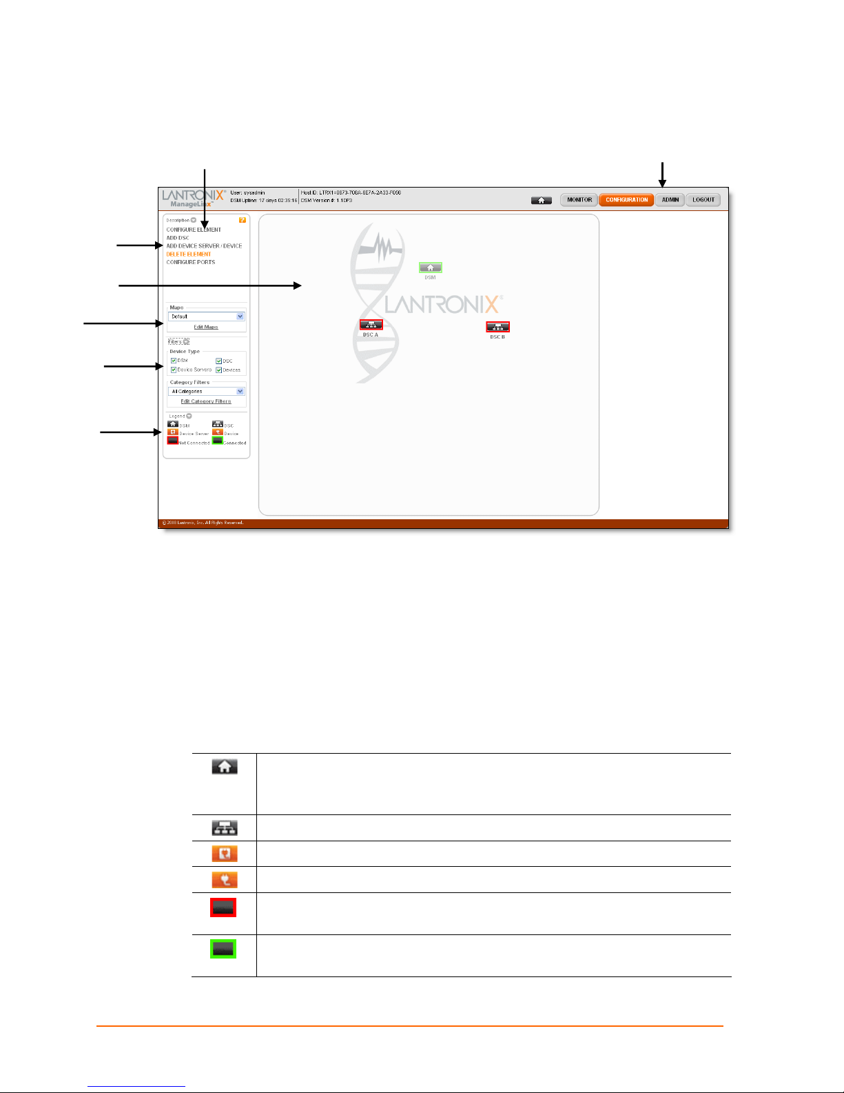
Command
Menu
Main View
Maps
Filters
Legend
One DSM and two DSC icons appear when you log in the first time.
Command Panel
5: Web Manager Guide
Navigation Bar
Web Manager User Interface Components
The ManageLinx Web Manager consists of a navigation bar on the top right, a command
panel on the left, and the main viewing area (map area). Each button on the navigation
bar shows its options in the command menu.
The main viewing area can display a map. You can place DSM, DSC, device server, and
device icons on the map for a visual representation of the location of each element.
Web Manager Icons
Icon for a DSM (also referred to as the Home icon).
Note: To add a DSM to a map, drag the icon onto the map.
Icon for a DSC.
Icon for a Lantronix Device Server.
Icon for a device residing on a network.
Red border around an element indicates it has been added to the Web
Manager but is not connected to the DSM.
Green border around an element indicates it is configured and connected
to the DSM.
ManageLinx User Guide 21
Page 22
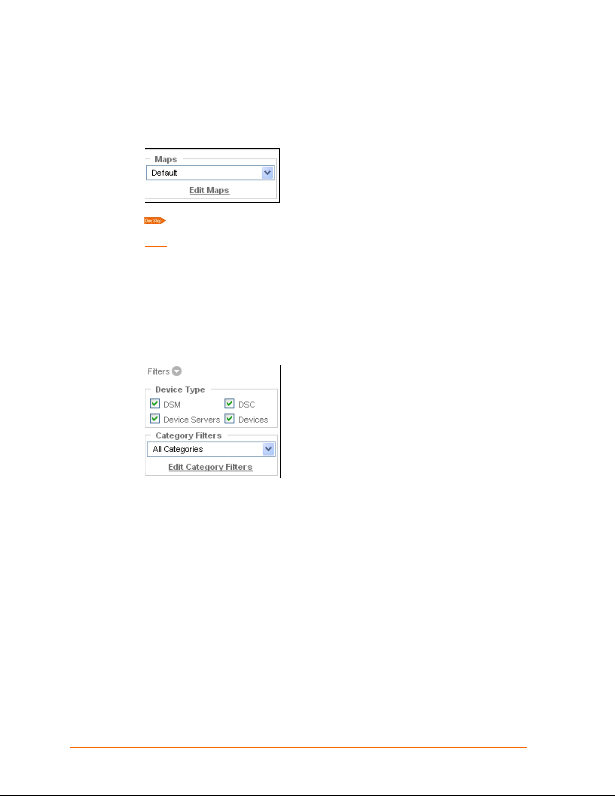
Web Manager Maps
Maps are the backgrounds you can use in the main viewing area. For example, you can
add, delete, and move icons on a map of the United States, a specific location, or any
graphic that is meaningful to you.
To display a map, select it from the Maps drop-down menu.
Note: If the map you select appears without the icons on the previous map, you need to
enable the map to show them. See
adding, editing, deleting, and using maps.
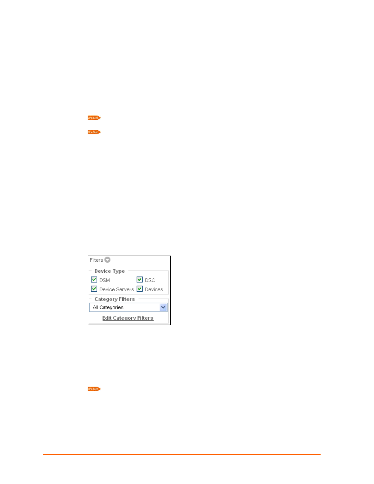
Web Manager Filters
Under the command menu are a series of filters that you can apply to the main viewing
area. To display filters, click the arrow beside the word Filters. The filters are set up in an
element’s configuration settings.
5: Web Manager Guide
10: Maps and Category Filters for information on
Device Type Filters: Select the device types viewable on the map. De-selecting a
device type only removes its visibility from the map; it does not permanently delete an
element.
Category Filters:
appear or disappear on the map. For example, to view only web cams, you can create a
filter called web cam and display only web cams in that filter. Select the category type
from the Category Filters drop-down list. To view all elements, select All Categories.
ManageLinx User Guide 22
You can create filters of your own. Filters allow you to make icons
Page 23
Web Manager Elements
Individual DSMs, DSCs, device servers, and other network devices are elements. Each
managed element has a corresponding entry in the ManageLinx Registry, which is an
internal database used to track all information in the system.
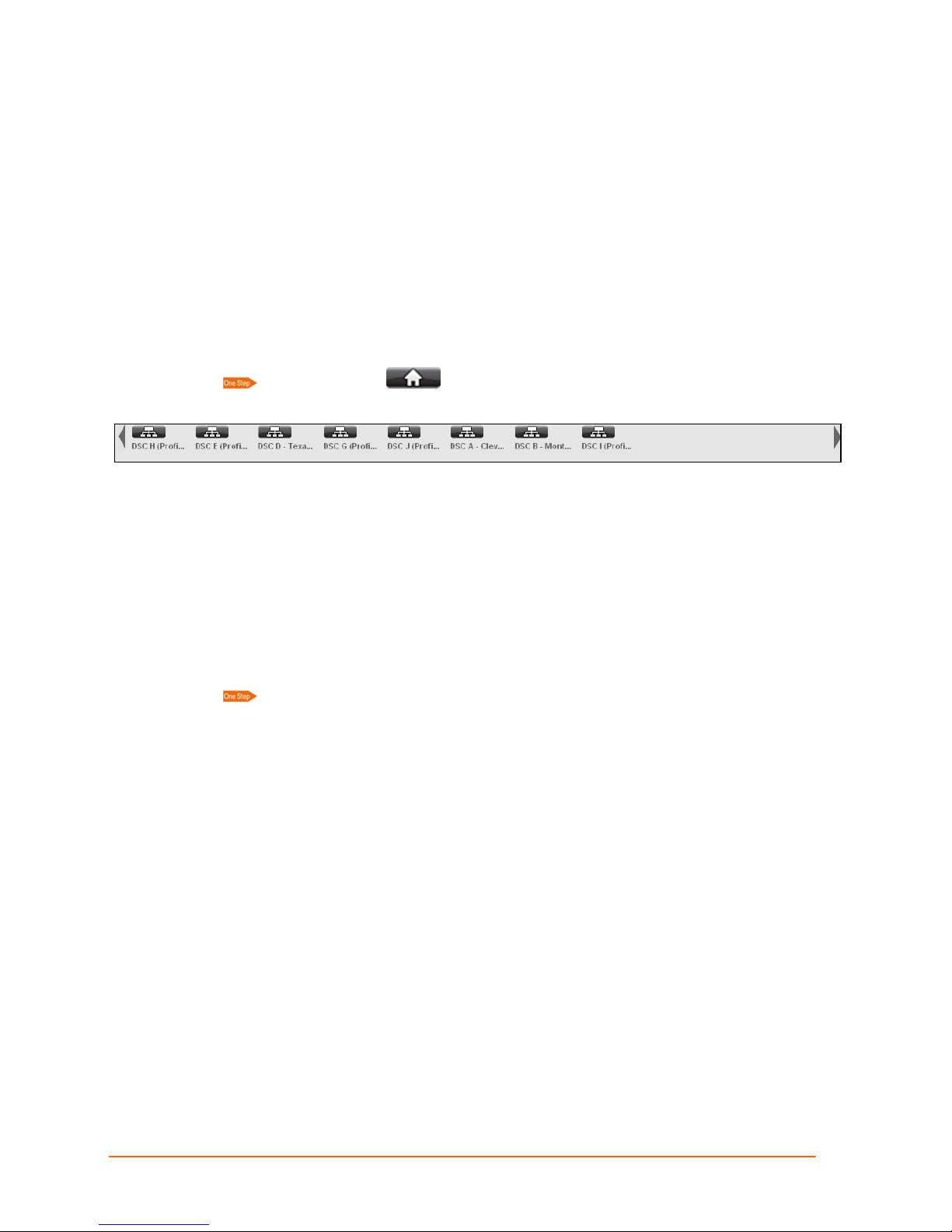
Viewing All Elements
Elements on the map can be shown or hidden by selecting the category filter in the
category list. All DSCs, device servers, and devices appear in the dock, which you can
display at the top of the page.
Click the home icon on the navigation bar. The icons of all elements
appear in the dock above the map.
You have the following options:
5: Web Manager Guide
Using the left and right arrows, scroll through the list of found and known elements.
Click the DSC icon on the dock to show a list of its children.
To add an element to the map, drag it from the dock and drop it onto the map.
Exiting the Web Manager
Click LOGOUT.
ManageLinx User Guide 23
Page 24
6: Network Settings
This chapter describes how to configure your network settings and network devices using
the Lantronix Web Manager.
Add and configure DSCs first then configure other devices and/or device servers.
Add a DSC
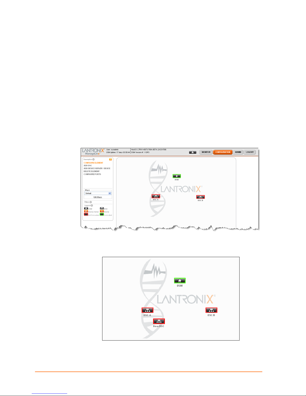
1. Click CONFIGURATION on the navigation bar.
6: Network Settings
2. Click ADD DSC on the command menu.
3. Click anywhere on the map to drop the new DSC. A new icon appears.
4. Continue with DSC Configuration below.
ManageLinx User Guide 24
Page 25
6: Network Settings
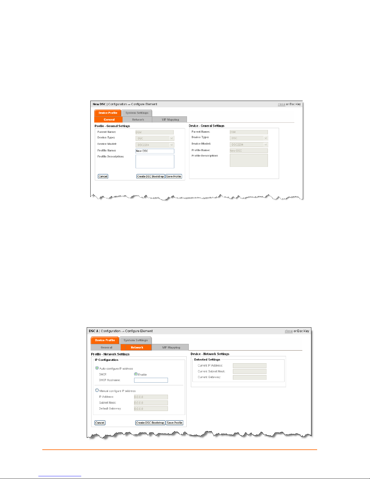
Configuring a Device Services Controller
Configure a DSC
1. Click Configure Element.
2. Click on the new DSC icon. The Configure Element page appears.
3. Enter a Profile Name or accept the default name, enter a Profile Description
(optional), and click Save Profile.
4. Continue with the next step, Configuring Network Settings.
Configuring Network Settings
Configuring Network Settings means assigning a dynamic or static IP address to the
DSC.
Auto-configuration is the Lantronix default and is dynamic, as set by the dynamic
host configuration protocol (DHCP).
Manual configuration is for assigning a static IP address.
Auto Configuration
1. Click the Network tab.
ManageLinx User Guide 25
Page 26

2. Select Auto-configure IP Address, and DHCP: Enable.
3. Enter a DHCP hostname (optional).
6: Network Settings
4. Click Save Profile and continue with
Creating and uploading a DSC Bootstrap File.
Manual Configuration
1. Click the Network tab.
2. Click Manual configure IP address.
3. Enter the static IP Address, the Subnet Mask, and the Default Gateway.
4. Click Save Profile and go to Creating a DSC Bootstrap File.
Creating and uploading a DSC Bootstrap File
You need to create and use a new bootstrap file in the following circumstance s:
When configuring a DSC for the first time
After deleting the DSC profile from the DSM and creating a new one
After changing the IP address of the DSM
Other settings, like VIPs, VIP routes and network settings for the DSC are sent from the
DSM to the DSC over the network.
The following steps copy network configuration information from the DSM to the Lantronix
flash drive that came with your unit.
1. Insert the Lantronix USB flash drive into a USB port on your PC or laptop.
2. Click Create DSC Bootstrap.
The DSM prompts you for a download location.
3. Browse to the Lantronix flash drive and click Open.
ManageLinx User Guide 26
Page 27
4. In the Save As dialog box (for I.E.), make sure to select the ‘Any File’ option in the
file type drop-down. The Web Manager creates a file called
the flash drive. Do not modify the DSC bootstrap filename.
The upload process begins at the DSM and the same bootstrap.dna file cannot be used
in another DSC
5. Insert the flash drive into the USB port on the front of the DSC. The DSC
automatically uploads the bootstrap file. When the DSC LED stops flashing the
process is complete. This may take several minutes.
6. Repeat steps 1-5 for each DSC in your ManageLinx network.
Adding Other Elements
You can add a device, or device server after their parent DSC has been configured.
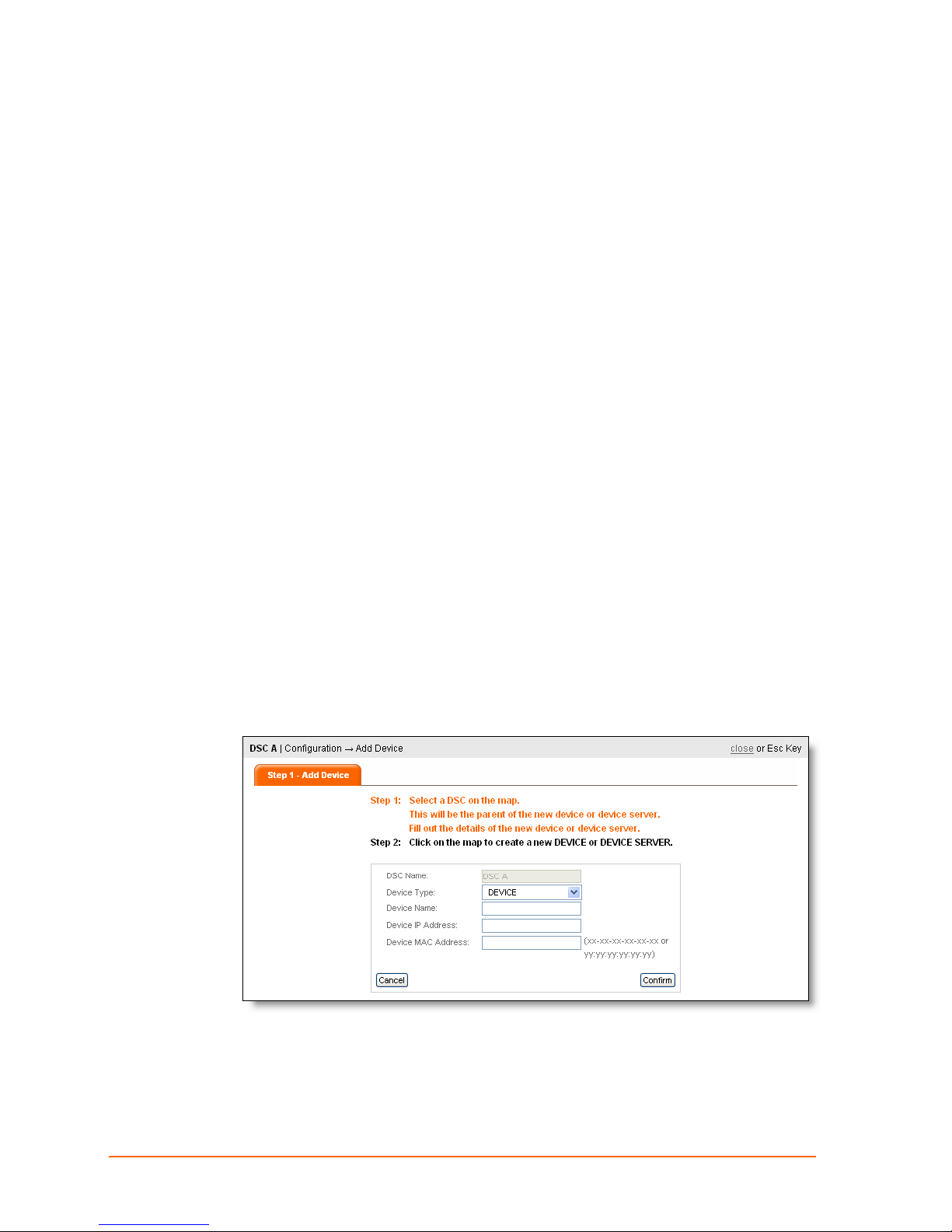
Adding a Device or Device Server
Device and device server elements represent the actual devices you will communicate
with over the Virtual Device Network.
6: Network Settings
bootstrap.dna on
A device server is usually a Lantronix hardware item (e.g. XPort, MatchPort). A device is
usually a non-Lantronix hardware item (e.g. webcam).
You must link each of these devices to a DSC via a physical network.
1. Click Configuration on the navigation bar.
2. Click Add Device Server or Device on the command menu, and click the icon
representing the DSC that will be connected to (and become the parent of) the
device. The Add Device page appears.
3. Follow the instructions on the page, and select Device or Device Serv er.
4. Enter the Device Name, IP Address, and MAC address.
ManageLinx User Guide 27
Page 28

6: Network Settings
5. Click Confirm.
6. Click the map where you want the device to appear. An icon representing the device
appears in that spot. You can drag it to another location anytime. If you do not click
the map, the device is not created.
ManageLinx User Guide 28
Page 29
7: Licensing
You may need to purchase, download and install additional licenses before you can
configure and use additional ManageLinx VIPs. Licenses can be acquired or activated
online at the Lantronix purchase license URL:
http://licensing.lantronix.com.
After you install the DSMs, and DSCs, and after you receive the license files, you must
add or upload the license files to the DSM.
Purchase a License
To fulfill a license by email, copy the Host ID number from the navigation bar, go to the
Lantronix purchase license URL:
there.
7: Licensing
http://licensing.lantronix.com and follow the instructions
When you receive the license file as an email attachment, copy the file to your PC VIA
File > Save Attachments. Remember the location where you stored it.
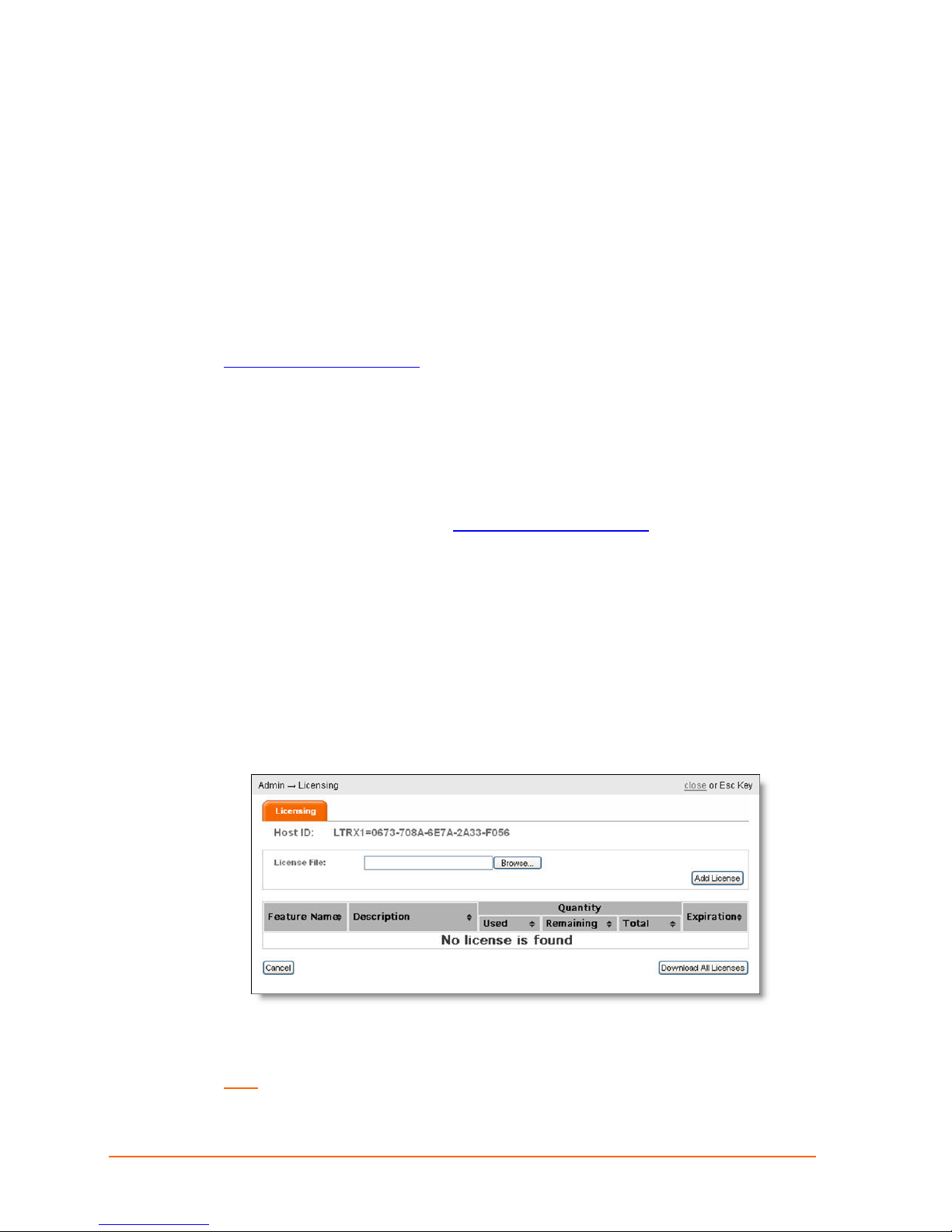
Add License File
Upload the license from a PC.
1. From the ManageLinx main page, click Admin > Licensing. The Licensing page
appears with the Host ID showing at the top.
The Host ID identifies the DSM you are logged onto. It is generated automatically by
the DSM.
Note: You will need this Host ID to purchase additional licenses.
ManageLinx User Guide 29
Page 30

7: Licensing
2. Click Browse to select the license file to be added to the DSM from your PC.
3. Click Add License. The new license is displayed in the table, indicating it has been
successfully uploaded to the DSM.
4. Repeat the process to load additional licenses you have purchased.
5. Click
close to return to the previous screen.
Display License Usage
The Licensing page shows a list of all the licenses that have been added. It is updated
every time a license is added.
Save Licenses to PC
This button allows you to download all the licenses from your DSM to your PC for backup
purposes. The licenses will be zipped into a .zip file.
ManageLinx User Guide 30
Page 31

8: Monitoring Devices
You can display device information for a selected element.
Viewing Device Settings
1. Click MONITOR on the navigation bar. Monitor options appear in the command
menu.
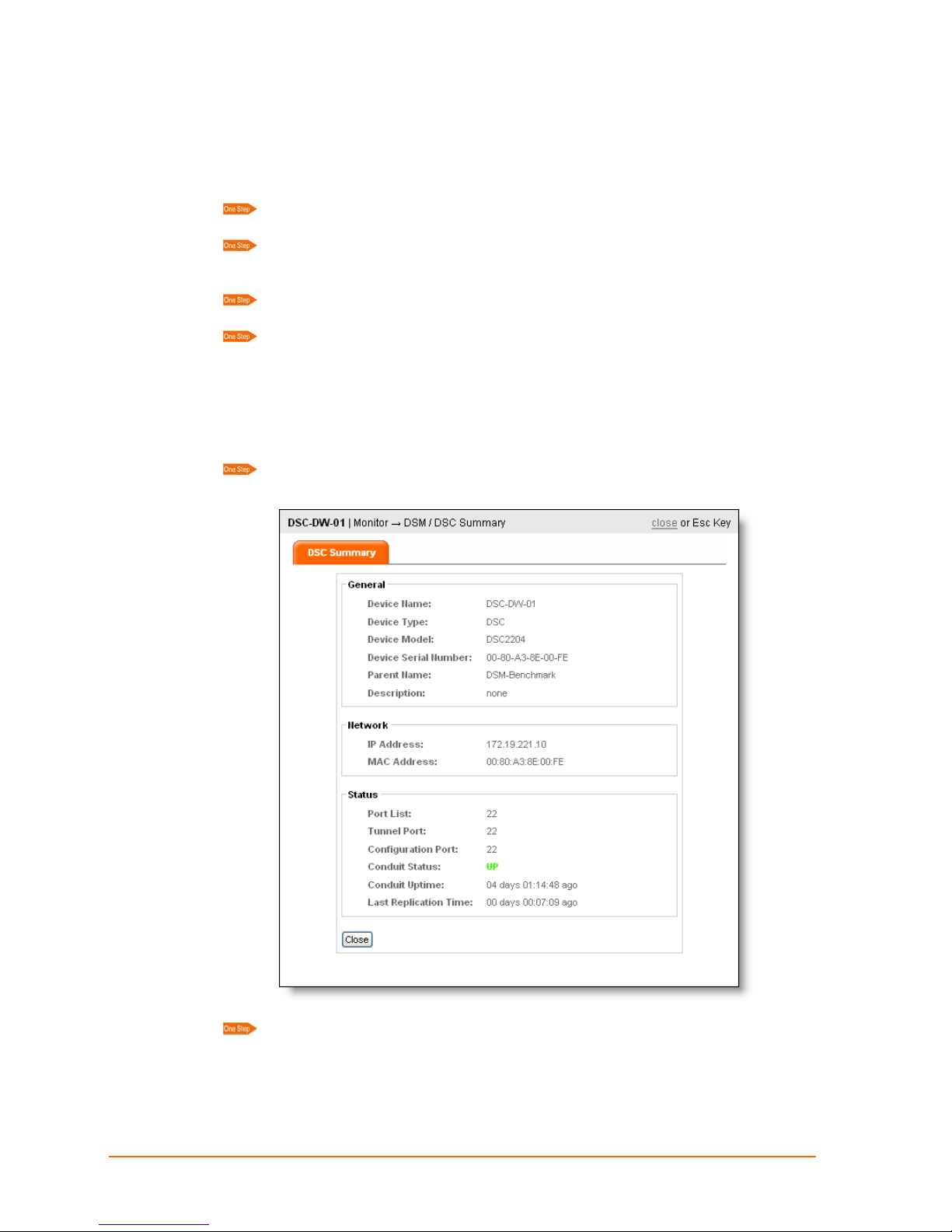
2. Click DSM/DSC SUMMARY on the command menu.
3. Click a device on the map. The DSM Summary page shows the device product type
and network settings.
8: Monitoring Devices
4. Click Close.
ManageLinx User Guide 31
Page 32
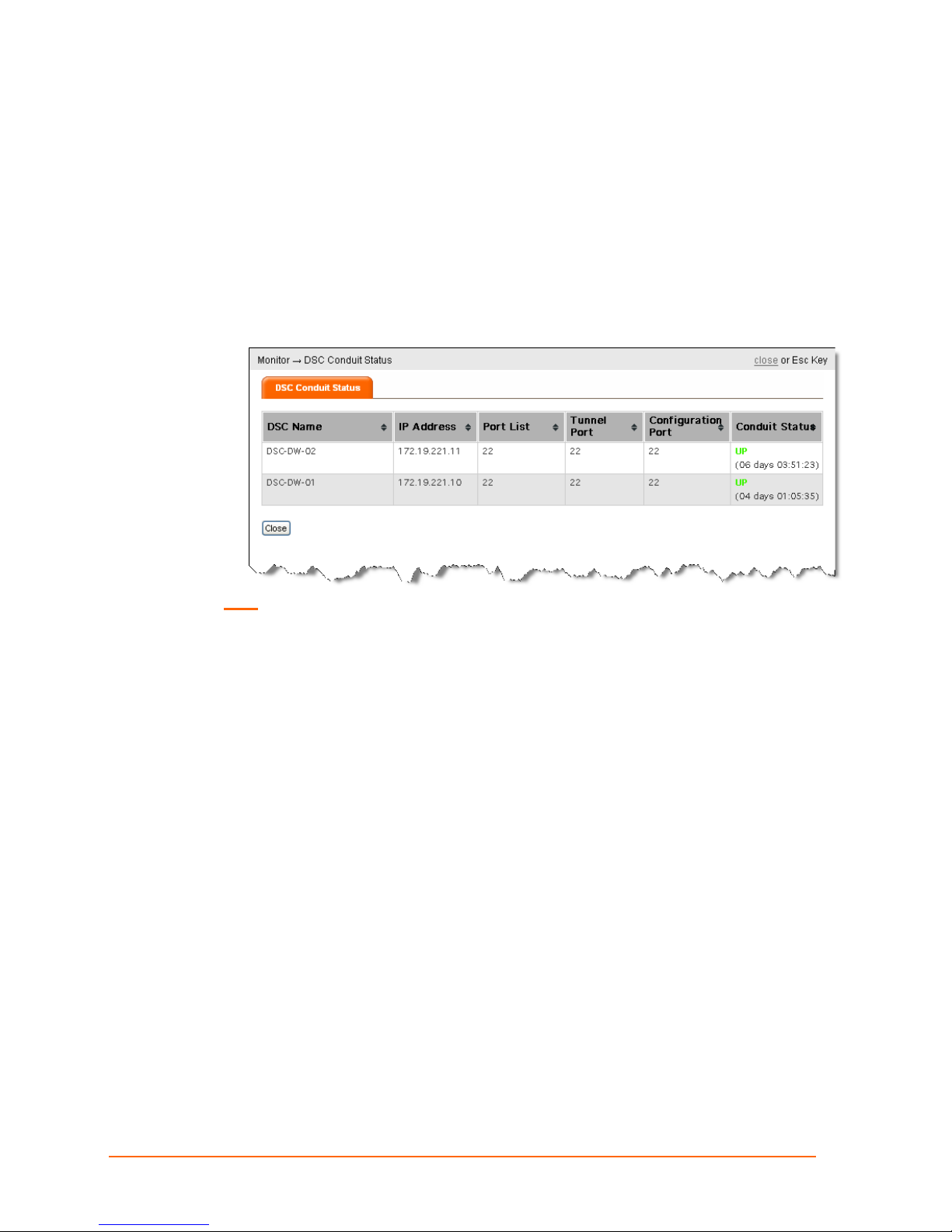
Viewing Conduit Status
A ManageLinx conduit is a secure encrypted channel through whi c h data flows between
the DSC and the DSM.
You can display information about the status of current conduits or connections.
1. Click the MONITOR button on the navigation bar. The Monitor options appear in the
command menu.
2. Click DSC CONDUIT STATUS on the command menu. The DSC Conduit Status
page appears.
8: Monitoring Devices
Note: The arrows to the right of each heading enable you to scroll through the list.
3. Click Close or press Esc to exit.
ManageLinx User Guide 32
Page 33
9: Route Configuration
Configurable items are elements on the map such as DSMs, DSCs, device servers, and
devices. You can configure element settings before physically connecting them to a
network.
DSM Ports
The DSM is expecting incoming connections from the DSCs to be made using p ort 22.
Since some firewall configurations prevent the usage of port 22 for outbound
connections, you can configure the DSM and DSC to use a different port
When you direct the host DSC to connect to a target DSC, the DSM will attempt to
connect to one of the ports in the list and will keep trying until it succeeds. The maximum
number of ports in the port list is 5.
9: Route Configuration
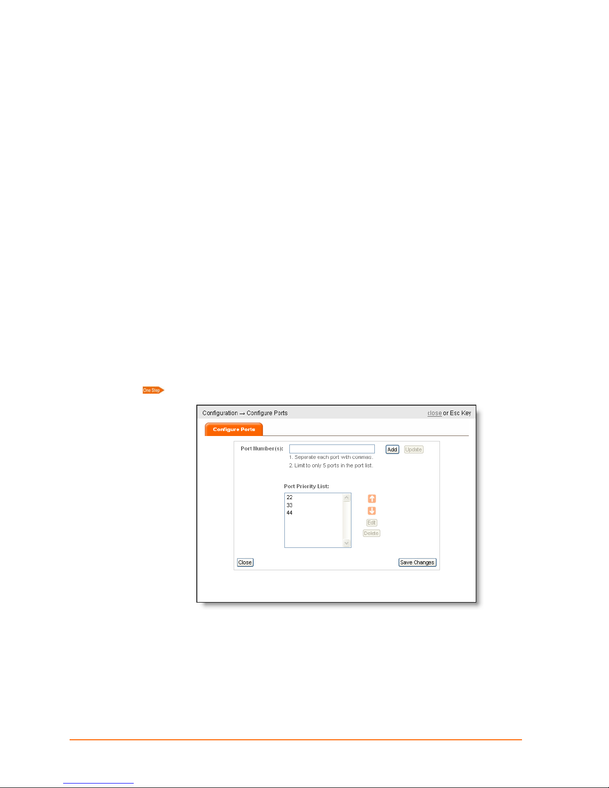
Configure Ports
Click Configuration > Configure Ports. The Configure Ports screen appears.
Here you can add, update, delete, or prioritize port numbers.
You can define a single port number (e.g. 80).
Port numbers must in the range of 1 through 65535.
The default port number is 22 and is always included in the list by default. You
may remove port 22 if you add another port number.
ManageLinx User Guide 33
Page 34
9: Route Configuration
Modifying the DSM port does not require bootstrapping the DSCs. This data is
propagated to the DSCs while they’re still connected to the DSM using the old
DSM port. Once all of the DSCs are connected to the DSM using the new DSM
port, the DSM will no longer accept DSC connections on the old DSM port.
To add a port, enter its number in the field provided and click Add.
To prioritize a port, select the port number and use the arrows to move it up or
down the list.
To edit a port, select the port number, and click Edit.
To delete a port, select the port number, and click Delete.
Display Ports
There are 2 screens that display port numbers used by the DSC: DSC Summary and
DSC Status.
Click Monitor > DSM / DSC Summary > DSC icon. The DSC Summary page
appears.
Click Monitor > DSC Conduit Status. The DSC Conduit Status page appears.
ManageLinx User Guide 34
Page 35
Configuring Elements
This section describes how to configure an element on the Device Profile tab. For
information on using the System Settings tab, see
40.
page
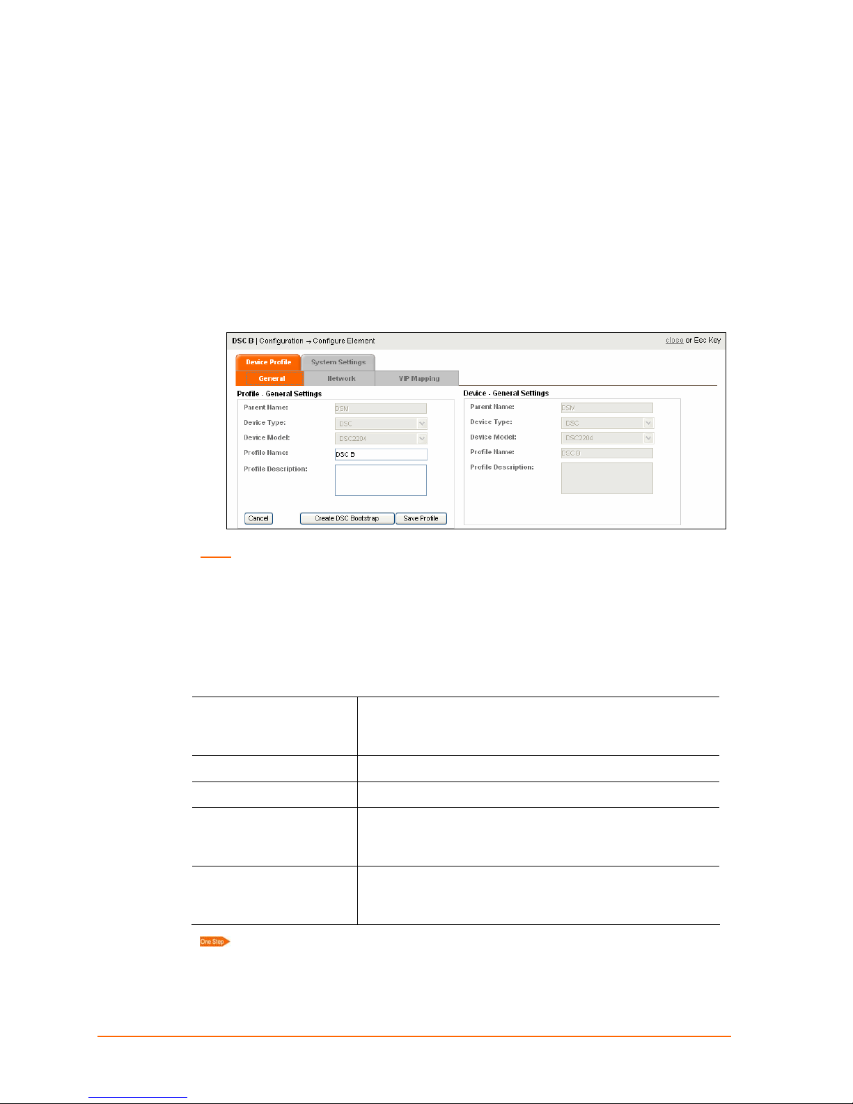
1. Click Configuration > Configure Element.
2. Click an element that is visible on the map. Its Configuration page opens, displaying
the General sub tab of the Device Profile tab. The Device Profile tab has three sub
tabs: General, Network, and VIP Mapping. The System Settings tab has two sub
tabs: Category Filters and Map Filters.
9: Route Configuration
Using Maps and Category Filters on
Note: When navigating between tabs, click Save Profile to ensure the configuration
changes are stored.
Device Profile: General Tab
On the General tab, the following information appears. Two fields are editable. A Profile
Name is required. A Profile Description is optional.
Profile General Settings
Parent Name
Device Type
Device Model
Profile Name
Profile Description
Non-editable field. Name of the parent of this
element. Blank for a DSM; DSM for a DSC; DSC for a
device.
Non-editable field.
Non-editable field. Appears for DSMs or DSCs only.
Enter a unique name for the device. Escape
characters (\0, \a, \b, \f, \n, \r, \t and \v) are treated as
special characters.
Enter the device description and other relevant
information. Escape characters (\0, \a, \b, \f, \n, \r, \t
and \v) are treated as special characters.
Enter a unique name for the device and click Save Profile.
ManageLinx User Guide 35
Page 36
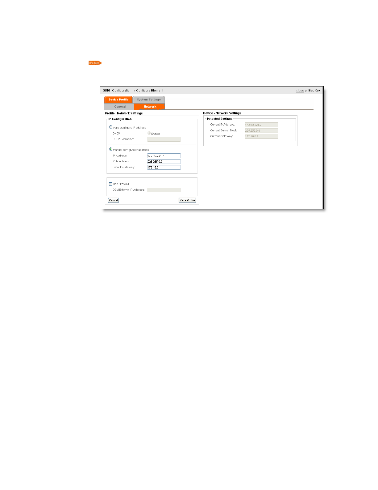
Device Profile: Network Tab
Click the Network tab.
When the system detects an element, the element IP Address, Subnet Mask,
and Gateway appear under Detected Settings.
9: Route Configuration
You may configure or modify the Network Settings under the IP Configuration section:
IP Configuration – Auto Configure IP Address
1. To auto configure the IP Address, select Auto Configure IP Address, and Enable.
2. Enter a DHCP hostname of up to 16 characters. The hostname must start with a
letter or digit and end with a letter or a digit. The hostname may consist of letters,
digits, and hyphens.
3. Click Save Profile.
IP Configuration – Manually Configure IP Address
1. To manually configure the IP Address, select Manual Configure IP Address.
2. Enter the device IP Address, subnet mask, and gateway.
3. Click Save Profile.
IP Configuration – Use Firewall
Only if your DSM is located behind a firewall, click this radio button and supply the IP
address of the firewall. This is the IP the DSCs will use to connect with the DSM.
Note: This option does not create a firewall. It only identifies the IP address of an
existing firewall.
1. Select Use Firewall to specify a firewall IP between the DSM and the remote
element.
ManageLinx User Guide 36
Page 37

2. Enter the IP address of the firewall device.
3. Click Save Profile.
Adding a DSC
1. Click Configuration on the navigation bar.
2. Select Add DSC on the command menu.
3. Click anywhere on the map. The DSC icon appears.
4. Configure the DSC as described earlier in this chapter.
Deleting an Element
1. Click Configuration on the navigation bar.
2. Select Delete Element on the command menu.
9: Route Configuration
3. Click the element on the map and in response to the confirmation prompt, click OK.
ManageLinx User Guide 37
Page 38

10: Maps and Category Filters
Category filters and maps enable you to hide and show the icons for the elements on the
main viewing area. This chapter describes several ways to add, edit, delete, and use
these helpful features.
Maps
For basic information about maps, see Web Manager Maps on page 22.
Adding a Map
1. Click Edit Maps link on the command panel. The Map Filters page appears. The list
box shows the default maps, which cannot be changed.
10: Maps and Category Filters
2. Enter Name and Description.
3. Click Browse and locate the map image file.
4. Click Save. The new map appears in the map list box.
5. Click Close.
ManageLinx User Guide 38
Page 39
10: Maps and Category Filters
Editing or Deleting a Map
You cannot edit or delete the default maps.
1. Click Edit Map List on the command panel. The Map Filters page appears.
2. From the drop-down list, click the name of the map.
3. You may either Delete or Edit the map:
To Delete the map, click the Delete Map button, and click OK.
To Edit the map:
5. Modify the map Name and Description.
6. Click Browse and locate a new map image file.
7. Click Save to save the changes.
8. Click close or press Esc to exit.
Filters
For basic information about filters, see Web Manager Filters on page 22.
Under the command menu are a series of filters that you can apply to the main viewing
area. The filters are set up in an element’s configuration settings.
Device Type Filters: Select the device types viewable on the map. De-selecting a
device type only removes its visibility from the map; it does not permanently delete an
element.
Category Filters: You can create filters of your own. For example, to view only web
cams, the user can create a filter called web cam and show only web cams in that filter.
Select the category type from the drop-down menu.
To view all elements, select All Categories.
ManageLinx User Guide 39
Page 40
10: Maps and Category Filters
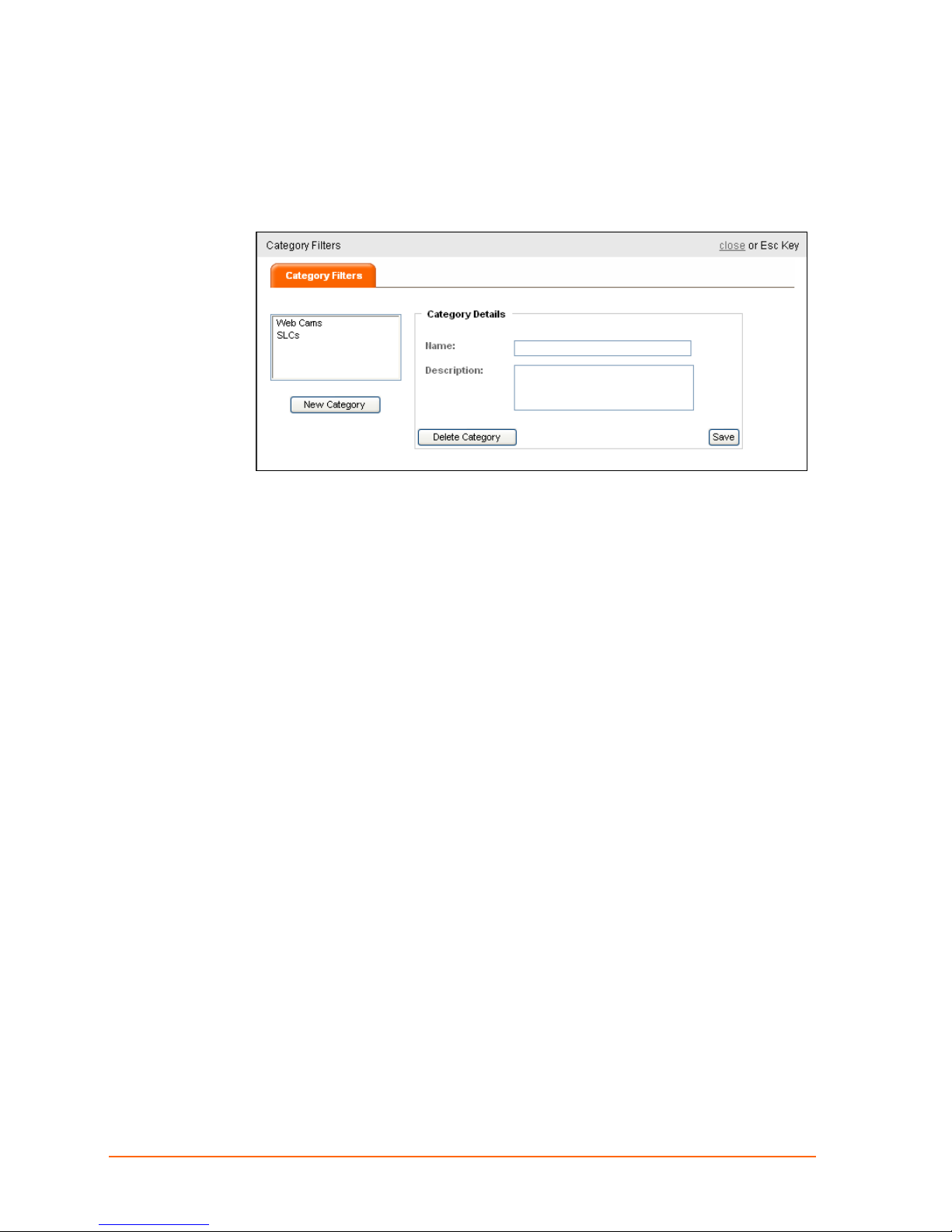
Adding a Category Filter
1. Click the Edit Category Filters link in the filters section of the command panel. The
Category Details page appears.
2. Enter the new category filter Name and Description.
3. Click Save.
The newly saved category filter appears in the category list. (See
Category Filters Tab
4. Click close. The filter appears in the Category Filters drop-down list in the command
panel.
on page 41 for information on defining a category filter.)
Editing or Deleting a Category Filter
1. Click the Edit Category Filters link. The Category Filters page appears.
2. From the category list, select the name of the category.
3. You have two options:
To delete the category, click Delete Category, and click OK.
To Edit the category, modify the category Name or Description and click Save.
4. Click close.
Using Maps and Category Filters
System Settings:
The Category Filters and Map Filters tabs on the Configuration page are for defining
when to show a specific element and when to hide it on the various maps.
1. Click Configuration > Configure Element > map icon. The Configure Element page
appears.
2. Click System Settings.
ManageLinx User Guide 40
Page 41
10: Maps and Category Filters
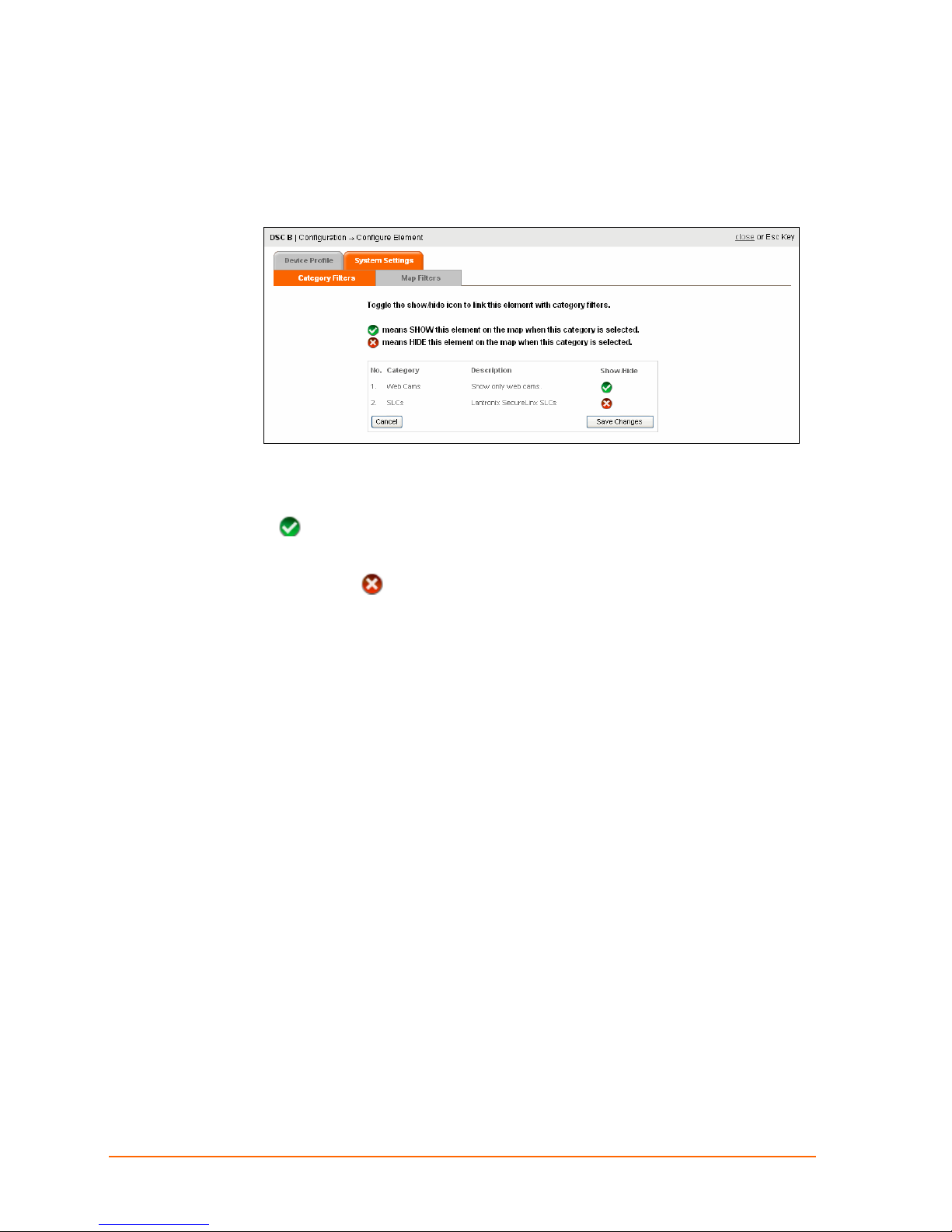
System Settings: Category Filters Tab
The Category Filters tab enables you to show or hide elements on specific maps.
1. Click Category Filters.
The list of available category filters appears. You have two options:
To include the element in a category, click the icon in the Show/Hide column. A
icon means show the element on the map when this category is selected.
To remove the element from a category, click the icon under the Show/Hide
column. An
selected.
In the figure above are two categories. But you are assigning the element to Web Cams
only.
2. Click the icon in the Show/Hide column to toggle the visibility of the device.
3. Click Save Changes.
icon means hide the element on the map when this category is
ManageLinx User Guide 41
Page 42

10: Maps and Category Filters
System Settings: Map Filters Tab
The Map Filters tab shows whether the element is shown or hidden on each of the
maps.
1. Click Map Filters.
The map Filters page appears.
By default, all elements are visible on the default map.
The
The
view.
2. Click Close.
icon means element appears when this map is selected for the main view.
icon means the element does not appear when this map is selected for the main
ManageLinx User Guide 42
Page 43
10: Maps and Category Filters
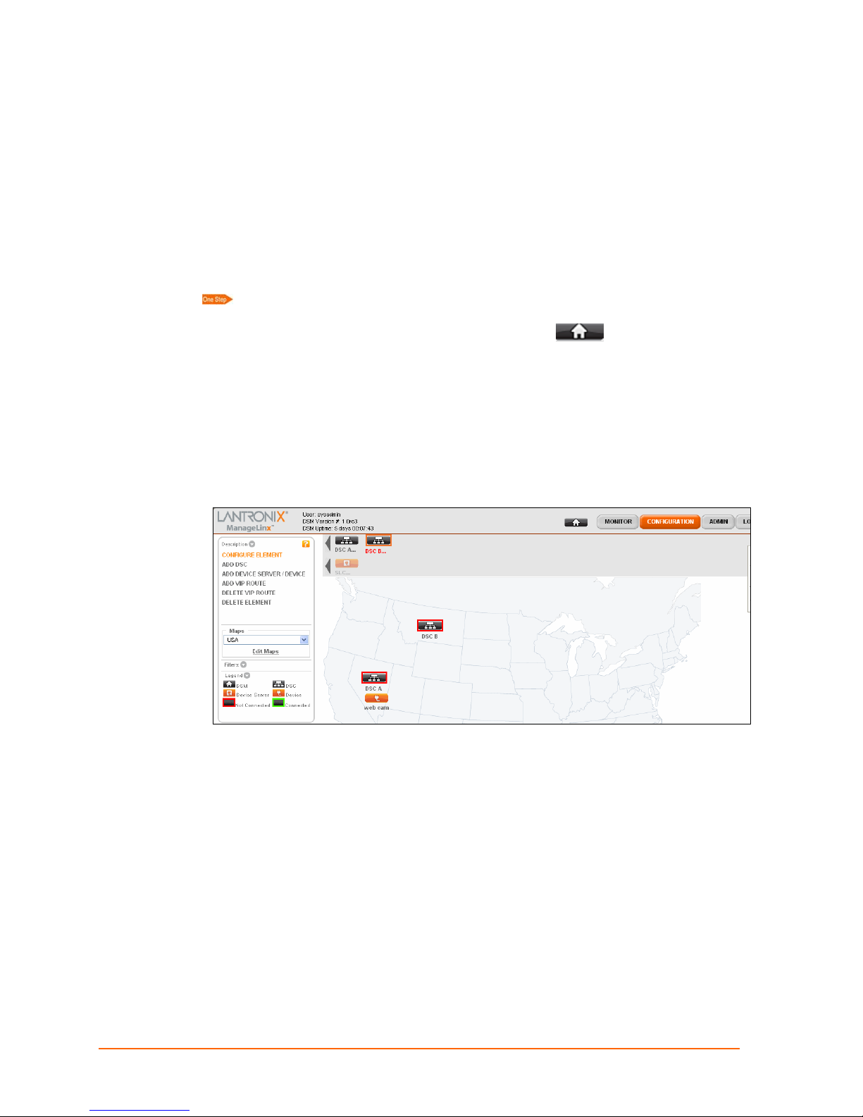
Hiding and Showing Elements on the Dock
When displaying a filter or a map, you can manually show or hide elements. All DSCs,
device servers, and devices are in the dock. (See
dock has two rows. The first row consists of all DSCs. When you click on a DSC in the
first row, the second row appears. This second row shows all the device servers and
devices related to that DSC.
The grayed-out icons on the dock are elements that are hidden on the map, whereas the
highlighted ones are those that appear on the map.
Select map and category filters. You have the following options:
To show a DSM on the map, click the DSM icon on the navigation bar
and drag it to the desired location on the map.
To show a DSC on the map, click and drag it from the first row of the dock to the
desired location on the map.
To show a device server or device on the map, click the dock element and drag it
from the second row on the dock to the desired location on the map.
Viewing All Elements on page 23.) The
To hide an element on the map, click the map element and drag it to the dock.
On the Map Filters tab for the element, a check icon appears for the map.
ManageLinx User Guide 43
Page 44

10: Maps and Category Filters
Map Filters with an Additional Map Selected
ManageLinx User Guide 44
Page 45

11: VIP Routes
This chapter describes how to configure DSCs and subordinate devices to communicate
across different networks—even through firewalls—by using VIP routes.
Console
11: VIP Routes
DSM
Public
Network
DSC-B
DSC-A
ManageLinx supports tunneling of TCP and UDP traffic. There is a slight difference
between the configuration and features of TCP tunneling vs.UDP tunneling.
Virtual IP Routes
A VIP Route is a mapping between a VIP on one DSC and a configured device (See
27, Adding Other Elements, for instructions regarding device configuration).
page
By creating the VIP route between VIP1 and Dev1, any device on subnet A can
communicate with Dev1 in subnet B, using the secure tunnel between the two networks
created by the DSM and the two DSCs.
A VIP is a virtual IP address assigned by you to a DSC.
You can configure any number of VIPs to a DSC, determined by your licensing
agreement with Lantronix.
DEV-1
TCP Tunneling
To create a TCP session between the console on subnet A and Dev1 on subnet B, the
console has to initiate the session. Then DSC A attempts to establish a TCP session
with Dev1. When the session is established, traffic can flow in both directions.
ManageLinx User Guide 45
Page 46

11: VIP Routes
The flow of data between the console and the device is bidirectional due to the nature of
TCP. However, the initiation of a session is possible only in one direction. For example, if
both Host1 and Dev1are Linux servers, an SSH client can log into the SSH server on
Dev1, but the SSH client on Dev1 cannot log into the SSH server on Host1.
Create a TCP VIP Route:
1. Click Configuration > Configure Element, select a DSC icon, and select the VIP
mapping tab.
2. Notice the Virtual IP License count in the upper left corner. See the chapter on
licensing to activate more licenses (page
29).
3. Click Add Row if you want to create another VIP.
4. Enter the Virtual IP Address and Netmask in dot-quad format, e.g. 255.255.255.0.
5. Proceed to the pull-down menu and select a target.
6. Click Save.
ManageLinx User Guide 46
Page 47

UDP Tunneling
The UDP tunneling feature of ManageLinx allows any host on subnet A to send UDP
packets. Once a VIP route has been configured, it will carry both TCP and UDP traffic.
However, the nature of UDP requires additional details—described below—to allow the
receiving device to send UDP datagrams in the opposite direction.
The underlying assumption for UDP tunneling is that a responding device uses the
source address of the packet it received when it wants to send a reply to the original
sender.
UDP VIP Route Types
ManageLinx supports the following types of UDP VIP routes.
Uni-directional—Allows a host on subnet A to send UDP datagrams to Dev1, but
does not expect Dev1 to send any response.
Bi-directional—Allows Host1 on subnet A to send a UDP packet to Dev1, while
attempting to assure that there are sufficient resources to support a UDP packet
going back from Dev1 to Host1. This is done by creating a VIP route from a VIP on
DSC2 to Host1.
11: VIP Routes
There are 2 types of Bi-directional routing:
Automatic Reverse Mapping—selects an unused VIP in the auto VIP pool to use to
send data from device B back to Host 1. This automatic route will remain open for a
few minutes even if there is no activity.
Manual Reverse Mapping—lets you manually configure Virtual IP routes in both
directions: a Virtual IP route from Host 1 to Device B and a VIP route from DSC B to
Host1. A static route thus established remains in effect until changed.
ManageLinx User Guide 47
Page 48
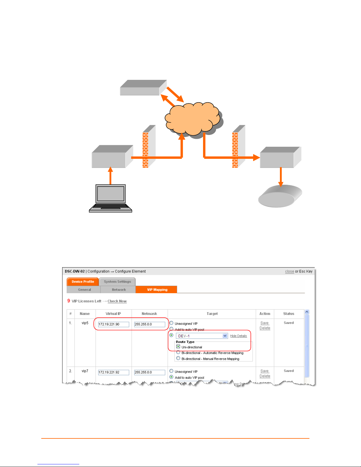
UDP Uni-Directional Routing
In UDP Uni-directional routing, DEV-A can send data to DEV-B.
DSM
Public
Network
DSC-A DSC-B
11: VIP Routes
Console
DEV-1
Configure Unidirectional VIP Route
Remember: Manually configured routings, like this, remain set until manually changed.
1. Click Configure > Configure Element > DSC-A > VIP Mapping.
2. Populate the Virtual IP and Netmask fields.
3. Select Target device, click Show Details, Uni-directional.
ManageLinx User Guide 48
Page 49

11: VIP Routes
4. Click Save.
Bi-directional Manual Reverse Mapping
Remember: Manually configured routings, like this, remain set until manually changed.
For reverse mapping, bi-directional scenarios, there has to be two Virtual IP routes:
One from the VIP on the originating device’s parent DSC (DSC-A) to the target
device (Printer).
One from the VIP on the target device’s parent DSC (DSC-B) to the originating
device (Console).
This figure shows that VIP 33.22.1.1 is configured on DSC A to send data to device
Printer. And DSC-B has configured VIP 22.22.22.22 to send data to the originating
device (Console).
Configure Bi-directional Manual Reverse Mapping
1. Configure DSC-A, Virtual IP 33.22.1.1, to Printer:
ManageLinx User Guide 49
Page 50
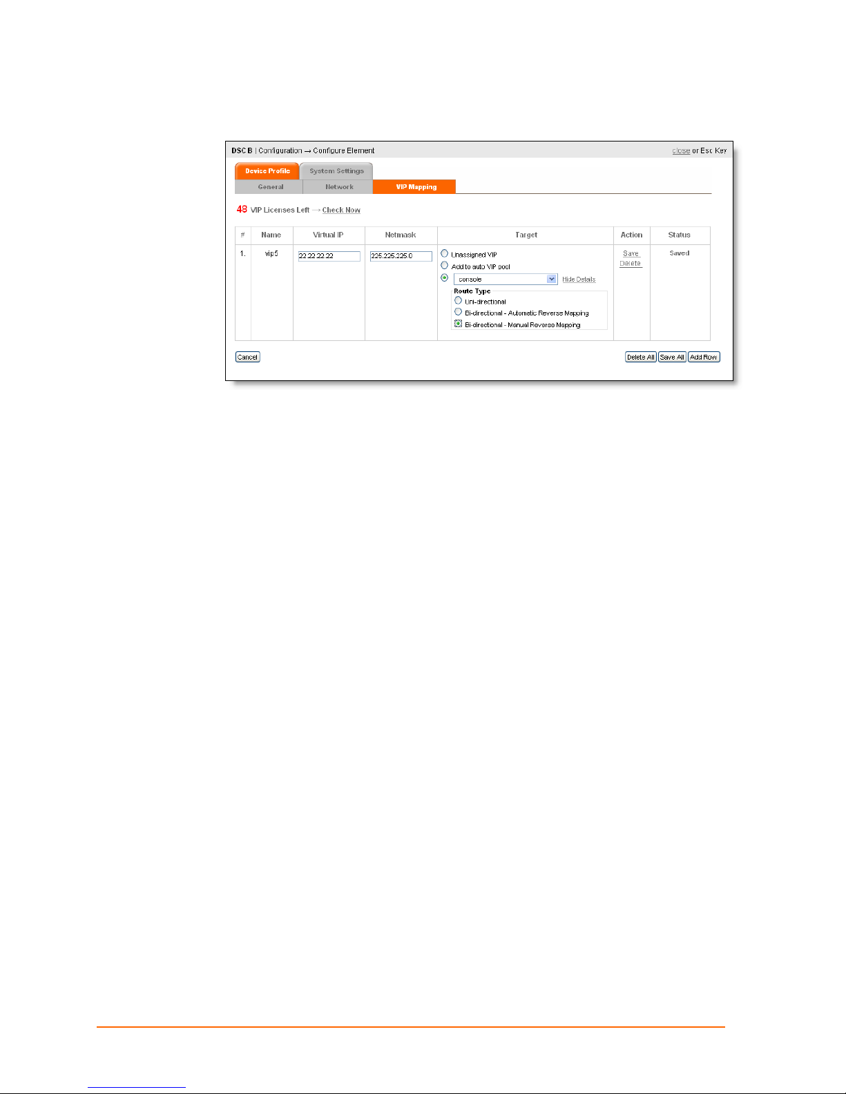
2. Configure DSC-B, Virtual IP 22.22.22.22, to Console:
11: VIP Routes
ManageLinx User Guide 50
Page 51
Console
11: VIP Routes
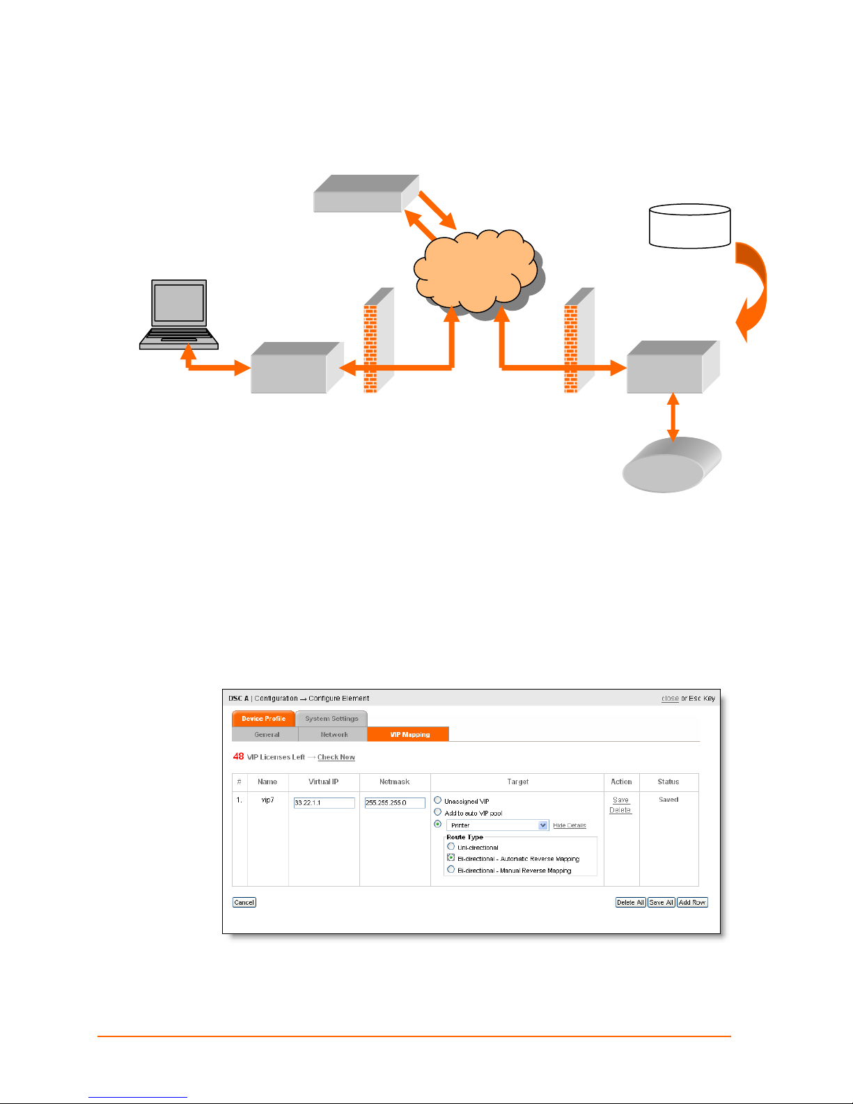
Bi-directional Automatic Reverse Mapping
In this case, you set the first route manually, but the second route, is assigned
automatically, using an unassigned VIP from the VIP pool.
DSM
VIP Pool
Public
Network
From DSC-A to
Printer
VIP 33.22.1.1
From DEV-B to
Console
VIP Auto.
DSC-A
This route remains in effect until communications have been inactive for a few minutes—
at which time the Virtual IP is returned to the pool and can be used by a different host.
A single VIP thus assigned, can be used by the parent DSC (DSC-B) to allow more than
one host to connect to the target device—like the printer in this case.
DSC-B
Printer
Configure Bi-directional Auto Reverse Mapping
1. Configure DSC-A, Virtual IP 33.22.1.1, to Printer, and click Bi-directional Automatic
Reverse Mapping.
5. Click Save. A VIP name is assigned and the status column updated.
ManageLinx User Guide 51
Page 52
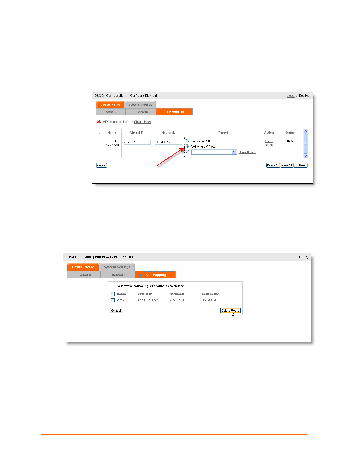
Add a VIP to the Pool
Follow these steps to add a VIP to the pool:
1. Click Configuration > DSC icon > VIP Mapping tab.
11: VIP Routes
2. Click Add to auto VIP pool.
3. Click Save.
Deleting a Route
1. Click Configuration, click a device icon, and click the VIP Mapping tab.
2. Click the checkbox of the route to the source DSC, and click Delete Route.
ManageLinx User Guide 52
Page 53

Deleting a VIP
1. Click Configuration, click a DSC icon, and click the VIP Mapping tab.
11: VIP Routes
2. Click Delete, on the row corresponding to the VIP to delete.
ManageLinx User Guide 53
Page 54

12: DSM Administration
Manage Global Settings
1. Click ADMIN > GLOBAL SETTINGS. The Global Settings page appears.
12: DSM Administration
2. Enter the frequency for the DSM and the DSC to synchronize their configuration.
Default is 10 minutes.
3. Do one of the following:
To store and apply new changes, click Apply Changes.
To reset the replication frequency to the default value, click Reset Settings and
click OK in response to the confirmation prompt. These defaults apply to these
global settings only. Click Apply Changes to store and apply new changes.
4. Click close.
Changing the ManageLinx Password
1. Click ADMIN > Change Password. The following page appears.
2. Click Change Password. Enter the current password, then enter the new password
in the two boxes provided.
3. Click Save and click close.
ManageLinx User Guide 54
Page 55
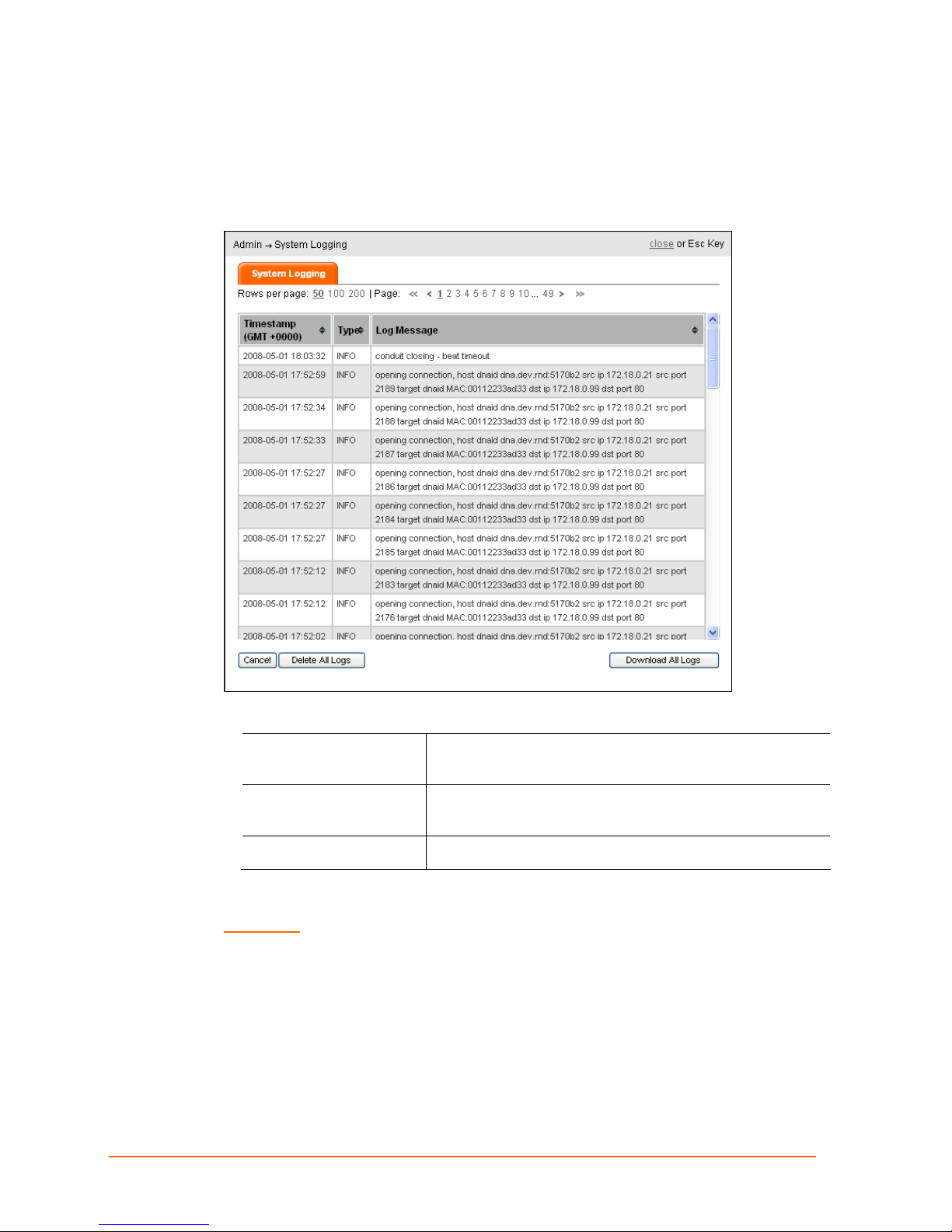
System Logging
View the system information log.
1. Click Admin > System Logging. The System Logging page appears.
12: DSM Administration
The following types of information are included:
Timestamp
Type
Log Message Detailed description of the log message
2. Click Download All Logs to save the system log in .csv format.
WARNING: In the next step, Clicking Delete All Logs, permanently erases the
system log.
3. Click Delete All Logs and click OK.
4. Click close.
Timestamp (in GMT +0000) when the message is
logged.
Message Type – At present, only INFO (informational
message) shows.
ManageLinx User Guide 55
Page 56
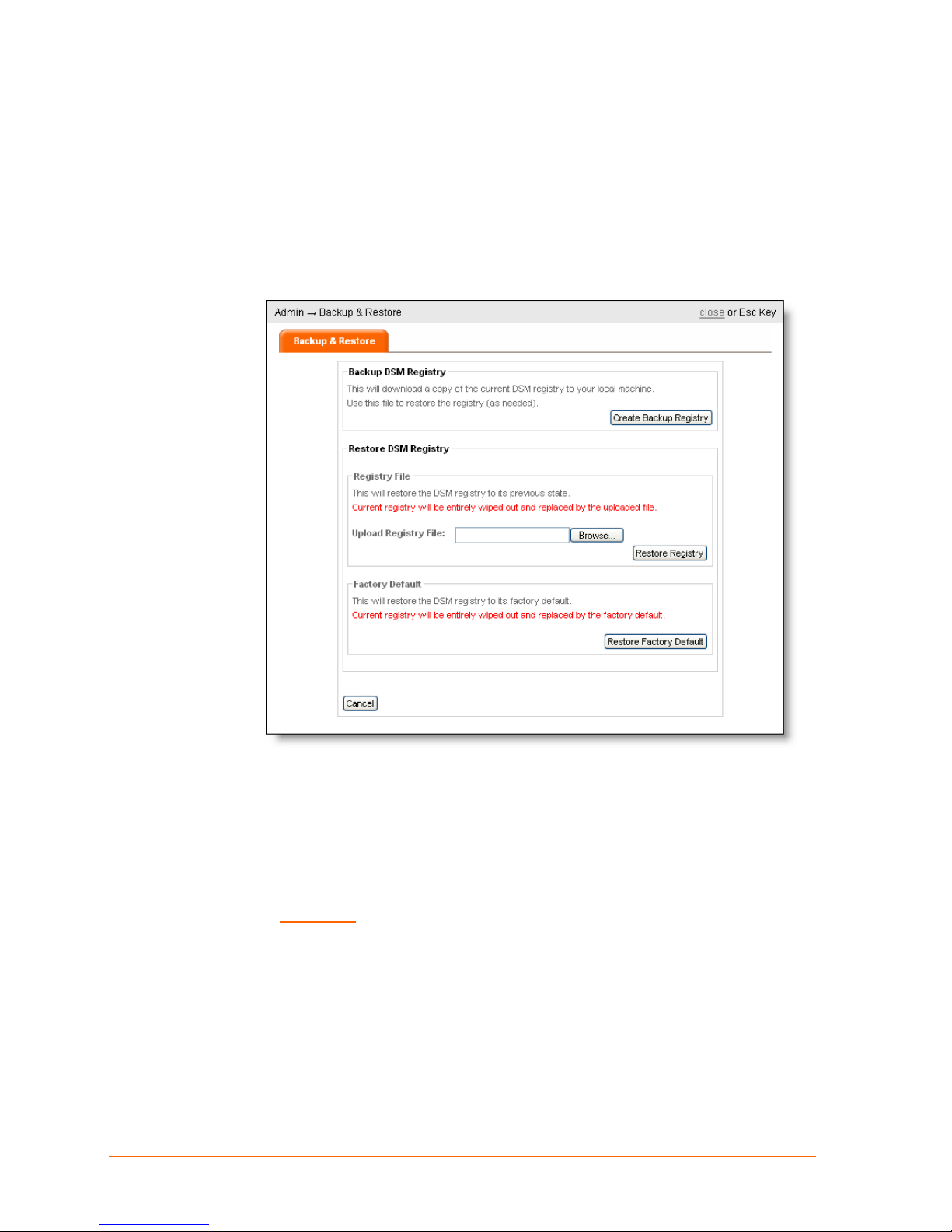
Backing up & Restoring System Settings
The DSM allows you to back up the current system settings and configurations. You can
retrieve the DSM registry backup later if necessary.
Backup the current system settings:
1. Click ADMIN > Backup & Restore. The Backup & Restore page appears.
12: DSM Administration
2. Click Create Backup Registry. When prompted, save the backup file.
3. Click close.
Restore the DSM from a backup registry file:
Use these steps to restore a system to its previous settings and configuration.
WARNING: Restoring the DSM registry completely erases its current
settings.
1. Click ADMIN > Backup & Restore. The Backup & Restore page appears.
2. Click Browse. Locate the backup file and click Open.
3. Click Restore Registry.
4. Click close.
ManageLinx User Guide 56
Page 57

Restore the DSM registry to its factory default:
Use these steps to replace the current registry with the factory default registry.
1. Click the ADMIN > Backup & Restore. The Backup & Restore page appears.
2. Click Restore Factory Default, and click OK in response to the confirmation prompt.
3. Click close.
Rebooting and Shutting Down the DSM
Reboot or Shutdown the DSM
1. Click ADMIN > REBOOT / SHUTDOWN DSM. The Reboot / Shutdown DSM page
appears.
12: DSM Administration
2. To reboot the DSM, click Reboot DSM and click OK.
3. To shut down the DSM, click Shutdown DSM and click OK.
4. Click close.
ManageLinx User Guide 57
Page 58
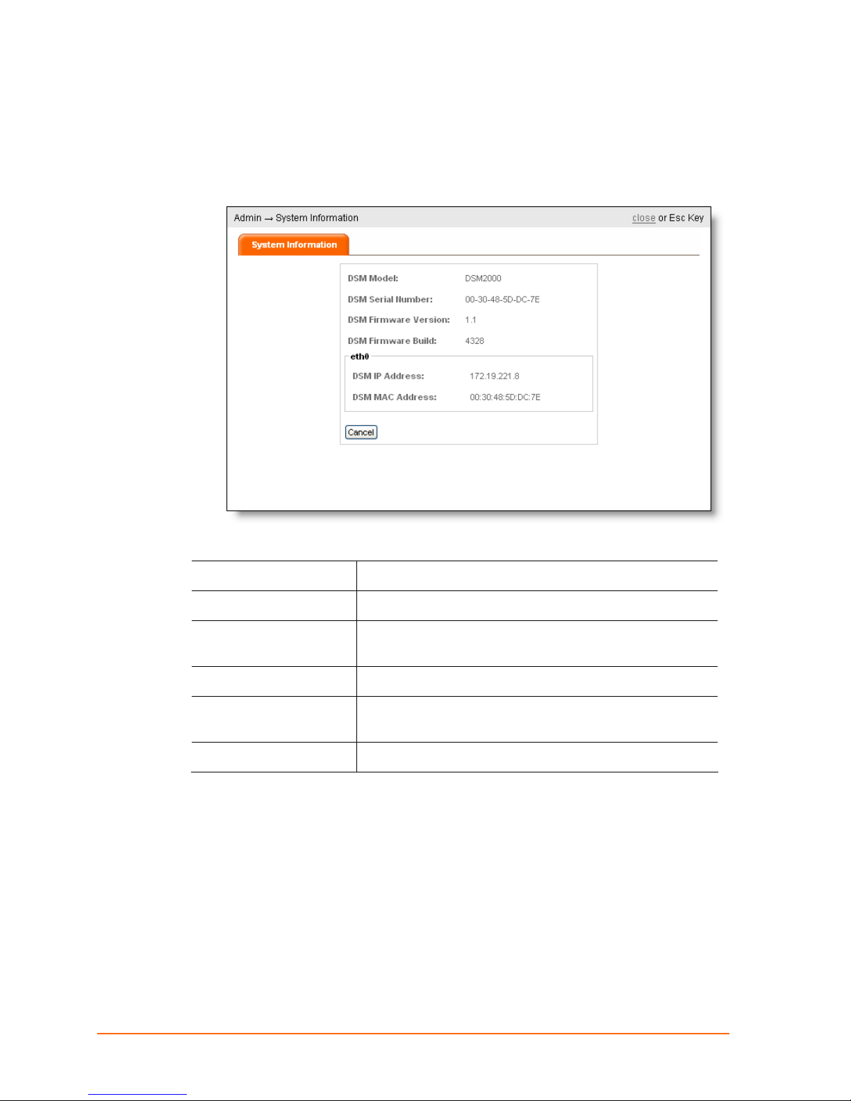
Viewing System Information
1. Click ADMIN > SYSTEM INFORMATION. The following page appears.
12: DSM Administration
The System Information page shows the following information about the DSM:
DSM Model
DSM Serial Number
DSM Firmware
Version
DSM Firmware Build
eth0 DSM MAC
Address
DSM IP Address
2. Click close.
Model number of the unit
Unique serial number for the unit
Version number of the DSM firmware on the unit
Build number of the DSM firmware on the unit
Hardware address of the unit
IP Address of the unit.
ManageLinx User Guide 58
Page 59
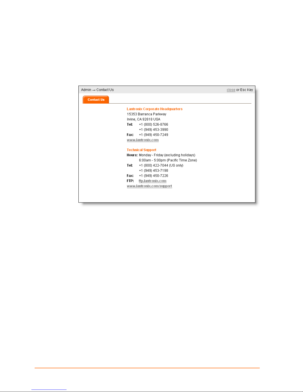
Lantronix Contact Information
View Lantronix contact information:
1. Click ADMIN > CONTACT US. The following page appears:
12: DSM Administration
2. Click close.
ManageLinx User Guide 59
Page 60

13: Technical Support and Warranty
13: Technical Support and Warranty
Technical Support
If you are experiencing an error that is not described in this chapter, or if you are unable
to fix the error, contact us as follows:
Technical Support US
C
heck our online knowledge base or send a question to Technical Support at
http://www.lantronix.com/support.
Phone: (800) 422-7044 (US Only)
(949) 453-7198
Technical Support Europe, Middle East, Africa
Phone: +33 1 39 30 41 72
Email: mailto:eu_techsupp@lantronix.com or mailto:eu_support@lantronix.com
Firmware downloads, FAQs, and the most up-to-date documentation are available at:
http://www.lantronix.com/support
When you report a problem, please provide the following information:
Your name, and your company name, address, and phone number
Lantronix model number
Lantronix serial number
Software version
Description of the problem
Debug report (stack dump), if applicable
Status of the unit when the problem occurred (please try to include information on
user and network activity at the time of the problem)
ManageLinx User Guide 60
Page 61

A: DSC Compliances
DSC compliance is according to ISO/IEC Guide 22 and EN 45014.
Manufacturer Name & Address
Lantronix 15353 Barranca Parkway, Irvine, CA 92618 USA
Declares that the following product:
Product Name: ManageLinx Device Services Controller (DS C) Model: DSC2204
conforms to the following standards or other normative documents:
Safety Standards Compliance
UL 60950-1
VCCI
C-TICK
Radiated and Conducted Emissions Compliance
FCC Part 15 Subpart B Class A
ICES-003 Issue 4 February 2004 Class A
VCCI V-3/2007.04 Class A
AS/NZS CISPR 22: 2006 Class A
EN55022: 2006 CLASS A
EN61000-3-2: 2000 + A2: 2005 Class A
EN61000-3-3: 1995 + A1: 2001 + A2: 2005
EN55024: 1998 + A1: 2001 + A2: 2005
Direct & Indirect ESD
EN55024/EN61000-4-2: 4kV Contact discharge/8kV Air discharge
RF Electromagnetic Field Immunity
EN55024/EN61000-4-3: 3V/m, 80 MHz to 1000 MHz, 80% AM (1 KHz)
ManageLinx User Guide 61
Page 62

Electrical Fast Transient/Burst Immunity
EN55024/EN61000-4-4: 1kV (peak) Common mode AC port
EN55024/EN61000-4-4: 0.5kV (peak) Common mode IO port
Surge Immunity
EN55024/EN61000-4-5: Common mode 2kV (peak) – line to earth (ground)
Differential mode 1kV (peak) – line to line
RF Common Mode Conducted Susceptibility
EN55024/EN61000-4-6: 3V rms 0.15 MHz to 80 MHz, 80% AM (1 KHz)
Power Frequency Magnetic Field Immunity
EN55024/EN61000-4-8: 50 Hz, 1.0A/m (rms)
Voltage Dips and Interrupts
EN55024/EN61000-4-11: > 95% reduction for 0.5 period
30% reduction for 25 seconds
> 95% reduction for 250 periods
RoHS Notice
All Lantronix products in the following families are China RoHS-compliant and free of the
following hazardous substances and elements:
1. Lead (Pb)
2. Cadmium
(Cd)
3. Mercury (Hg)
4. Hexavalent Chromium
(Cr (VI))
5. Polybrominated biphenyls (PBB)
6. Polybrominated diphenyl ethers (PBDE)
ManageLinx User Guide 62
Page 63

Toxic or Hazardous Substances and Elements
Toxic or hazardous Substances and Elements Product Family Name
Lead
(Pb)
UDS1100 and 2100 0 0 0 0 0 0
EDS 0 0 0 0 0 0
MSS100 0 0 0 0 0 0
IntelliBox 0 0 0 0 0 0
XPress DR & XPress-
DR+
SecureBox 1101 0 0 0 0 0 0
WiBox 0 0 0 0 0 0
UBox 0 0 0 0 0 0
MatchPort 0 0 0 0 0 0
SLC 0 0 0 0 0 0
XPort 0 0 0 0 0 0
WiPort 0 0 0 0 0 0
SLB 0 0 0 0 0 0
SLP 0 0 0 0 0 0
SCS 0 0 0 0 0 0
SLS 0 0 0 0 0 0
O: toxic or hazardous substance contained in all of the homogeneous materials for this part is below the limit requirement in SJ/T11363-2006.
X: toxic or hazardous substance contained in at least one of the homogeneous materials used for this part is above the limit requirement in SJ/T11363-2006.
0 0 0 0 0 0
Mercury
(Hg)
Cadmium
(Cd)
Hexavalent
Chromium
(Cr (VI))
Polybrominated
biphenyls (PBB)
Polybrominated
diphenyl ethers (PBDE)
Manufacturer’s Contact
Director of Quality Assurance, Lantronix
15353 Barranca Parkway, Irvine, CA 92618 USA
Tel: 949-453-3990
Fax: 949-453-3995
ManageLinx User Guide 63
Page 64

B: Warranty
For details on the Lantronix warranty replacement policy, go to our web site at
www.lantronix.com/support/warranty.
ManageLinx User Guide 64
Page 65

Index
A
Adding a Device or Device Server, 27
Adding a DSC, 37
Adding a Map, 38
Additional Documentation, 7
Addresses, 10
IP, 10
Auto-configure, 25
B
Backing up & Restoring System Settings,
56
Bootstrap, 18, 26
C
Changing the ManageLinx Password, 54
Compliance, 61
Configuration, 33
Configuration Methods, 9
Configuration profiles, 9
Configure an IP Address Automatically,
17, 26
Configuring Network Settings, 14
H
Hardware address, 10
Hiding and Showing Elements on the
Dock, 43
Host ID, 29
I
Installing and Configuring the DSC, 15
Installing and Configuring the DSM, 13
IP Address, 10
L
Label, 9
LEDs, 11, 12, 18, 27
M
Manage Global Settings, 54
ManageLinx Registry, 23
Manual configure, 25
Manufacturer’s Contact, 63
Maps, 6, 22, 35, 38, 40
Maps and Category Filters, 38
Monitoring Devices, 31
D
Deleting an Element, 37
Device Profile: General Tab, 35
Device Profile: Network Tab, 36
DHCP hostname, 17, 26
DSC Compliance, 61
DSC Installation, 15
DSM Administration, 54
DSM Installation, 12
E
Editing or Deleting a Category Filter, 40
Editing or Deleting a Map, 39
Enter a static IP Address, 14
F
Filters, 22, 35, 38, 39, 40, 41, 42, 43, 44
ManageLinx User Guide 65
N
Network Configuration, 24
P
Port Numbers, 10
Product Information Label, 9
Product Name, 61
Profile General Settings, 35
Purpose and Audience, 6
R
Radiated and Conducted Emissions, 61
Rebooting and Shutting Down the DSM,
57
replacement policy, 64
RoHS Notice, 62
Page 66

S
Safety, 61
Specifications, 10
Static IP Address, 14
Summary of Chapters, 6
System Settings: Category Filters Tab, 41
System Settings: Map Filters Tab, 42
T
Technical Support, 60
Toxic or Hazardous Substances, 63
U
Using Maps and Category Filters, 40
V
Viewing All Elements, 23
Viewing Conduit Status, 32
Viewing Contact Information, 59
Viewing Device Settings, 31
Viewing or Exporting System Logs, 55
Viewing System Information, 58
VIP Routes, 45
W
Warranty, 60, 64
Web Manager
Elements, 23
Exiting, 23
Filters, 22
Maps, 22
Web Manager
Icons, 21
User Interface Components, 21
Web Manager Navigation, 20
ManageLinx User Guide 66
 Loading...