

Page 1
XPort Pro Lx6
Embedded Device Server
User Guide
Part Number 900-688-R
Revision A December 2013
Page 2

Intellectual Property
© 2013 Lantronix, Inc. All rights reserved. No part of the contents of this book may be transmitted
or reproduced in any form or by any means without the written permission of Lantronix.
Lantronix and XPort are registered trademarks of Lantronix, Inc. in the United States and other
countries. DeviceInstaller is a trademark of Lantronix, Inc. U.S. Patents 6,881,096; 7,018,242.
Additional patents pending.
Windows and Internet Explorer are registered trademarks of Microsoft Corporation. Mozilla and
Firefox are registered trademarks of the Mozilla Foundation. Chrome is a trademark of Google,
Inc. Safari is a registered trademark of Apple, Inc. Wi-Fi is a trademark of Wi-Fi Alliance
Corporation. All other trademarks and trade names are the property of their respective holders.
Warranty
For details on the Lantronix warranty policy, please go to our web site at
www.lantronix.com/support/warranty
Contacts
Lantronix, Inc.
Corporate Headquarters
.
167 Technology Drive
Irvine, CA 92618, USA
Toll Free: 800-526-8766
Phone: 949-453-3990
Fax: 949-453-3995
Technical Support
Online: www.lantronix.com/support
Sales Offices
For a current list of our domestic and international sales offices, go to the Lantronix web site at
www.lantronix.com/about/contact
Disclaimer
The information in this guide may change without notice. The manufacturer assumes no
responsibility for any errors that may appear in this guide.
Revision History
Date Rev. Comments
December 2013 A Initial document for 7.5.0.0.
.
XPort® Pro Lx6 Embedded Device Server User Guide 2
Page 3

Table of Contents
Intellectual Property ________________________________________________________2
Warranty _________________________________________________________________2
Contacts _________________________________________________________________2
Disclaimer ________________________________________________________________2
Revision History ___________________________________________________________2
List of Figures _____________________________________________________________7
List of Tables _____________________________________________________________8
1: Using This Guide 10
Purpose and Audience _____________________________________________________10
Summary of Chapters ______________________________________________________10
Additional Documentation ___________________________________________________11
2: Introduction 12
Key Features _____________________________________________________________12
Applications ______________________________________________________________12
Protocol Support _________________________________________________________13
Troubleshooting Capabilities _________________________________________________13
Configuration Methods _____________________________________________________13
Addresses and Port Numbers ________________________________________________14
Hardware Address _____________________________________________________14
IP Address ___________________________________________________________14
Port Numbers _________________________________________________________14
Product Information Label ___________________________________________________14
3: Using DeviceInstaller 16
Accessing XPort Pro Lx6 Using DeviceInstaller __________________________________16
Device Detail Summary _____________________________________________________16
4: Configuration Using Web Manager 18
Accessing Web Manager ___________________________________________________18
Device Status Page ________________________________________________________19
Web Manager Components _________________________________________________20
Navigating Web Manager ___________________________________________________21
5: Network Settings 23
Network Interface Settings __________________________________________________23
To Configure Network 1 Interface Settings ___________________________________24
XPort® Pro Lx6 Embedded Device Server User Guide 3
Page 4

To View Network 1 Interface Status ________________________________________25
Network (Ethernet Network “eth0”) Link Settings _________________________________25
To Configure Network 1 Link Settings ______________________________________26
6: Line and Tunnel Settings 27
Line Settings _____________________________________________________________27
To Configure Line Settings _______________________________________________28
To View Line Statistics __________________________________________________29
Tunnel Settings ___________________________________________________________29
Tunnel Settings ___________________________________________________________29
Serial Settings ________________________________________________________29
To Configure Tunnel Serial Settings ________________________________________30
Packing Mode _________________________________________________________30
To Configure Tunnel Packing Mode Settings _________________________________31
Accept Mode __________________________________________________________31
To Configure Tunnel Accept Mode Settings __________________________________33
Connect Mode ________________________________________________________33
To Configure Tunnel Connect Mode Settings ________________________________35
Disconnect Mode ______________________________________________________35
To Configure Tunnel Disconnect Mode Settings ______________________________36
Modem Emulation ______________________________________________________36
To Configure Tunnel Modem Emulation Settings ______________________________37
Statistics _____________________________________________________________37
To View Tunnel Statistics ________________________________________________37
7: Terminal and Host Settings 38
Terminal Settings _________________________________________________________38
To Configure the Terminal Network Connection _______________________________39
To Configure the Terminal Line Connection __________________________________39
8: Configurable Pin Manager 40
CPM: Configurable Pins ____________________________________________________40
CPM: Groups _________________________________________________________41
To Configure CPM Settings ______________________________________________42
9: Services Settings 43
DNS Settings _____________________________________________________________43
To View or Configure DNS Settings: _______________________________________43
FTP Settings _____________________________________________________________44
To Configure FTP Settings _______________________________________________44
Syslog Settings ___________________________________________________________44
To View or Configure Syslog Settings ______________________________________45
XPort® Pro Lx6 Embedded Device Server User Guide 4
Page 5

HTTP Settings ____________________________________________________________45
To Configure HTTP Settings _____________________________________________46
To Configure HTTP Authentication _________________________________________46
10: Maintenance and Diagnostics Settings 48
Filesystem Settings ________________________________________________________48
File Display ___________________________________________________________48
To Display Files _______________________________________________________48
File Modification _______________________________________________________49
File Transfer __________________________________________________________49
To Transfer or Modify Filesystem Files ______________________________________50
Protocol Stack Settings _____________________________________________________50
IP Settings ___________________________________________________________50
To Configure IP Network Stack Settings ____________________________________50
ICMP and ICMPv6 Settings ______________________________________________51
To Configure ICMP Network Stack Settings __________________________________51
To View ICMPv6 Network Stack Settings ____________________________________51
ARP Settings _________________________________________________________51
To Configure ARP Network Stack Settings __________________________________52
SMTP Settings ________________________________________________________52
To Configure SMTP Network Stack Settings _________________________________52
Diagnostics ______________________________________________________________53
Hardware ____________________________________________________________53
To View Hardware Information ____________________________________________53
IP Sockets ___________________________________________________________53
To View the List of IP Sockets ____________________________________________53
Ping ________________________________________________________________54
To Ping a Remote Host _________________________________________________54
Traceroute ___________________________________________________________54
To Perform a Traceroute ________________________________________________54
Log _________________________________________________________________55
To Configure the Diagnostic Log Output ____________________________________55
Memory ______________________________________________________________55
To View Memory Usage _________________________________________________55
Processes ____________________________________________________________56
To View Process Information _____________________________________________56
Threads _________________________________________________________________56
To View Thread Information ______________________________________________56
System Settings __________________________________________________________57
To Reboot or Restore Factory Defaults _____________________________________57
Discovery ____________________________________________________________58
XPort® Pro Lx6 Embedded Device Server User Guide 5
Page 6

11: Advanced Settings 59
Email Settings ____________________________________________________________59
To View, Configure and Send Email ________________________________________59
Command Line Interface Settings _____________________________________________60
Basic CLI Settings _____________________________________________________60
To View and Configure Basic CLI Settings ___________________________________60
Telnet Settings ________________________________________________________61
To Configure Telnet Settings _____________________________________________61
XML Settings _____________________________________________________________61
XML: Export Configuration _______________________________________________61
To Export Configuration in XML Format _____________________________________62
XML: Export Status _____________________________________________________62
To Export in XML Format ________________________________________________63
XML: Import Configuration _______________________________________________63
To Import Configuration in XML Format _____________________________________64
12: Updating Firmware 65
Obtaining Firmware ________________________________________________________65
Loading New Firmware through Web Manager __________________________________65
Loading New Firmware through FTP __________________________________________66
13: Branding the XPort Pro Lx6 67
Web Manager Customization ________________________________________________67
Short and Long Name Customization __________________________________________68
To Customize Short or Long Names _______________________________________68
Appendix A: Technical Support 69
North America ____________________________________________________________69
Europe, Middle East, Africa (EMEA) ___________________________________________69
Japan __________________________________________________________________69
Asia / Pacific (APAC) ______________________________________________________69
Latin America & Caribbean __________________________________________________69
Online __________________________________________________________________70
Appendix B: Compliance 71
Appendix C: Binary to Hexadecimal Conversions 73
Converting Binary to Hexadecimal ____________________________________________73
Conversion Table ______________________________________________________73
Scientific Calculator ____________________________________________________73
XPort® Pro Lx6 Embedded Device Server User Guide 6
Page 7

List of Figures
Figure 2-1 XPort Pro Lx6 Product Label _______________________________________________15
Figure 4-1 Device Status Page ______________________________________________________19
Figure 4-2 Components of the Web Manager Page ______________________________________20
Figure 12-1 Uploading New Firmware ________________________________________________65
XPort® Pro Lx6 Embedded Device Server User Guide 7
Page 8

List of Tables
Table 4-3 Web Manager Pages _____________________________________________________21
Table 5-1 Network Interface Settings _________________________________________________23
Table 5-2 Network 1 (eth0) Link Settings ______________________________________________25
Table 6-1 Line Configuration Settings ________________________________________________27
Table 6-2 Line Command Mode Settings ______________________________________________28
Table 6-3 Tunnel Serial Settings ____________________________________________________30
Table 6-4 Tunnel Packing Mode Settings _____________________________________________30
Table 6-5 Tunnel Accept Mode Settings ______________________________________________32
Table 6-6 Tunnel Connect Mode Settings _____________________________________________34
Table 6-7 Tunnel Disconnect Mode Settings ___________________________________________35
Table 6-8 Tunnel Modem Emulation Settings __________________________________________36
Table 7-1 Terminal on Network and Line Settings _______________________________________38
Table 8-1 Current Configurable Pins _________________________________________________40
Table 8-2 CP Status ______________________________________________________________40
Table 8-3 CPM Group Current Configuration ___________________________________________41
Table 8-4 CPM Group Status _______________________________________________________41
Table 9-1 DNS Settings ___________________________________________________________43
Table 9-2 FTP Settings ___________________________________________________________44
Table 9-3 Syslog Settings _________________________________________________________44
Table 9-4 HTTP Settings __________________________________________________________45
Table 9-5 HTTP Authentication Settings ______________________________________________46
Table 10-1 File Display Settings ____________________________________________________48
Table 10-2 File Modification Settings _________________________________________________49
Table 10-3 File Transfer Settings ____________________________________________________49
Table 10-4 IP Network Stack Settings ________________________________________________50
Table 10-5 ICMP Network Stack Settings _____________________________________________51
Table 10-6 ARP Network Stack Settings ______________________________________________51
Table 10-7 SMTP Protocol Stack Settings _____________________________________________52
Table 10-8 Ping Settings __________________________________________________________54
Table 10-9 Traceroute Settings _____________________________________________________54
Table 10-10 Log Settings __________________________________________________________55
Table 10-11 System Settings _______________________________________________________57
Table 10-12 CLI Configuration Default Settings _________________________________________57
Table 10-13 Line Configuration Default Settings _______________________________________58
Table 10-14 Network Configuration Default Settings _____________________________________58
XPort® Pro Lx6 Embedded Device Server User Guide 8
Page 9

Table 10-15 Tunnel Default Settings _________________________________________________58
Table 10-16 Discovery Settings _____________________________________________________58
Table 11-1 Email Configuration _____________________________________________________59
Table 11-2 CLI Configuration Settings ________________________________________________60
Table 11-3 Telnet Settings ________________________________________________________61
Table 11-4 XML Exporting Configuration ______________________________________________62
Table 11-5 Exporting Status ________________________________________________________62
Table 11-6 Import Configuration from Filesystem Settings ________________________________63
Table 13-1 Short and Long Name Settings ____________________________________________68
Table C-1 Binary to Hexadecimal Conversion __________________________________________73
XPort® Pro Lx6 Embedded Device Server User Guide 9
Page 10

1: Using This Guide
Purpose and Audience
This guide provides the information needed to configure, use, and update the Lantronix® XPort®
Pro Lx6 embedded device server and application server. It is intended for software developers and
system integrators who are embedding this product into their designs.
Summary of Chapters
The remaining chapters in this guide include:
Chapter Description
2: Introduction Main features of the product and the protocols it supports.
3: Using DeviceInstaller Instructions for viewing the current configuration using
4: Configuration Using Web Manager Instructions for accessing Web Manager and using it to configure
5: Network Settings Instructions for configuring network settings.
6: Line and Tunnel Settings Instructions for configuring line and tunnel settings.
7: Terminal and Host Settings Instructions for configuring terminal and host settings.
8: Configurable Pin Manager Information about the Configurable Pin Manager (CPM) including
9: Services Settings Instructions for configuring DNS, FTP, HTTP and Syslog settings.
10: Maintenance and Diagnostics
Settings
11: Advanced Settings Instructions for configuring email, CLI and XML settings.
12: Updating Firmware Instructions for obtaining the latest firmware and updating the
13: Branding the XPort Pro Lx6 Instructions on how to brand your device.
Appendix A: Technical Support Instructions for contacting Lantronix Technical Support.
Appendix B: Compliance Lantronix compliance information.
Appendix C: Binary to Hexadecimal
Conversions
Includes technical specifications.
DeviceInstaller.
settings for the device.
how to set the configurable pins to work with a device and
instructions for accessing Web Manager and using it to configure
settings for the device.
Instructions to maintain the XPort Pro Lx6, view statistics, files,
and diagnose problems.
XPort Pro Lx6.
Instructions for converting binary values to hexadecimals.
XPort® Pro Lx6 Embedded Device Server User Guide 10
Page 11

Additional Documentation
Visit the Lantronix Web site at www.lantronix.com/support/documentation for the latest
documentation and the following additional documentation.
Document Description
XPort Pro Embedded Device
Server Integration Guide
XPort Pro Lx6 Embedded Device
Server Command Reference
XPort Embedded Device Server
Universal Demo Board
Quick Start Guide
DeviceInstaller Online Help Instructions for using the Lantronix Windows-based utility to locate the
1: Using This Guide
Information about the XPort Pro Lx6 hardware, testing the device
server using the demonstration board, and integrating the unit into your
product.
Instructions for accessing Command Mode (the command line
interface) using a Telnet connection or through the serial port. Detailed
information about the commands. Also provides details for XML
configuration and status.
Instructions for getting the XPort Pro Lx6 embedded device server up
and running.
embedded device server and to view its current settings.
XPort® Pro Lx6 Embedded Device Server User Guide 11
Page 12

2: Introduction
The XPort Pro Lx6 embedded Ethernet device server is a complete network-enabling solution in a
30 (1.181) X 55 (2.165) X 6.45 (0.248) package. This miniature device server empowers original
equipment manufacturers (OEMs) to go to market quickly and easily with Ethernet networking and
web page serving capabilities built into their products.
Key Features
Power Supply: Regulated 3.3V input required. There is a step-down converter to 1.5V for the
processor core and 1.8V for the memory subsystem. All voltages have LC filtering to minimize
noises and emissions.
Controller: MCF520X microprocessor running at 166.67 megahertz (Mhz) with 8 Kilobyte
(KB) Configurable Cache.
Memory: Up to 16 MB SDRAM, 16 MB Flash and 16KB Internal SRAM.
Ethernet: 10/100 megabits per second (Mbps) Ethernet transceiver.
One 10Base-T or 100Base-TX Ethernet Port
Serial Ports: One high speed RS232/RS485 serial port baud rate support from 300 to
921600. Baud rate of 460800 is not supported
Interface Signals: 3.3V-level interface signals.
Configurable IO Pins (CPs): Up to three pins are configurable as general purpose I/Os if no
modem control signal is used on serial ports. Not 5V tolerant.
Configuration via CLI, XML and HTTP.
Temperature Range: Operates over a temperature range of -40°C to +85°C (-40°F to 185°F).
The storage temperature range is -40°C to 85°C (-40°F to 185°F).
Applications
The XPort Pro Lx6 embedded device server connects serial devices such as those listed below to
Ethernet networks using the IP protocol family.
ATM machines
CNC controllers
Data collection devices
Universal Power Supply (UPS) management unit
Telecommunications equipment
Data display devices
Security alarms and access control devices
Handheld instruments
Modems
Time/attendance clocks and terminals
XPort® Pro Lx6 Embedded Device Server User Guide 12
Page 13

Patient Monitoring Devices
Glucose Analyzers
Infusion Pumps
Protocol Support
The XPort Pro Lx6 embedded device server contains a full-featured IP stack. Supported protocols
include:
ARP, SNMP v1/v2c/v3, IPv4, IPv6, UDP, TCP, ICMP, BOOTP, DHCP, DHCPv6, Auto IP,
Telnet, and FTP
DNS, TFTP, and Syslog for network communications and management.
TCP, UDP, and Telnet tunneling to the serial port.
TFTP for uploading/downloading files.
FTP and HTTP for firmware upgrades and uploading/downloading files.
2: Introduction
Troubleshooting Capabilities
The XPort Pro Lx6 offers a comprehensive diagnostic toolset that lets you troubleshoot problems
quickly and easily. Available from the CLI or Web Manager, the diagnostic tools let you:
View memory and IP socket information
Perform ping and traceroute operations
Conduct forward or reverse DNS lookup operations
View all processes currently running on the XPort Pro Lx6, including CPU utilization
View system log messages
Configuration Methods
After installation, the XPort Pro Lx6 requires configuration. For the unit to operate correctly on a
network, it must have a unique IP address on the network. There are four basic methods for
logging into the XPort Pro Lx6 and assigning IP addresses and other configurable settings:
Web Manager: View and configure all settings easily through a web browser using the
Lantronix Web Manager. (See “Configuration Using Web Manager” on page 18.)
DeviceInstaller: Configure the IP address and related settings and view current settings on
the XPort Pro Lx6 using a Graphical User Interface (GUI) on a PC attached to a network. You
will need the latest version of Lantronix® DeviceInstaller™ utility. (See “Using DeviceInstaller”
on page 16.)
Command Mode: There are a few methods for accessing Command Mode (CLI): making a
Telnet connection or via the serial port (when configured accordingly). (See the XPort Pro Lx6
Embedded Device Server Command Reference Guide for instructions and available
commands.)
XPort® Pro Lx6 Embedded Device Server User Guide 13
Page 14

XML: The XPort Pro Lx6 supports XML-based configuration and setup records that make
Note: The hardware address on the
label is the address for the Ethernet
(eth0) interface. For example, if the
product label hardware address is 00-80A3-14-1B-18, then the Ethernet address
is 00-80-A3-14-1B-18.
device configuration transparent to users and administrators. XML is easily editable with a
standard text or XML editor. (See the XPort Pro Lx6 Embedded Device Server Command
Reference Guide for instructions and commands.)
Addresses and Port Numbers
Hardware Address
The hardware address is also referred to as the Ethernet address, physical address, or MAC
address. Sample hardware address:
00-80-A3-14-1B-18
00:80:A3:14:1B:18
IP Address
Every device connected to an IP network must have a unique IPv4 or IPv6 address. This address
references the specific unit.
2: Introduction
Port Numbers
Every TCP connection and every UDP datagram is defined by a destination and source IP
address, and a destination and source port number. For example, a Telnet server commonly uses
TCP port number 23.
The following is a list of the default server port numbers running on the XPort Pro Lx6:
TCP Port 23: Telnet Server (Command Mode configuration)
TCP Port 80: HTTP (Web Manager configuration)
TCP Port 21: FTP
TCP/UDP Port 10001: Tunnel 1 (see note below)
Note: Additional TCP/UDP ports and tunnels will be available, depending on the product
type. The default numbering of each additional TCP/UDP port and corresponding tunnel
will increase sequentially (i.e., TCP/UDP Port 1000X: Tunnel X).
Product Information Label
The product information label on the unit contains the
following information about the specific unit:
Bar code
Product Revision
Part Number
Hardware Address (MAC Address)
Manufacturing Date Code
XPort® Pro Lx6 Embedded Device Server User Guide 14
Page 15
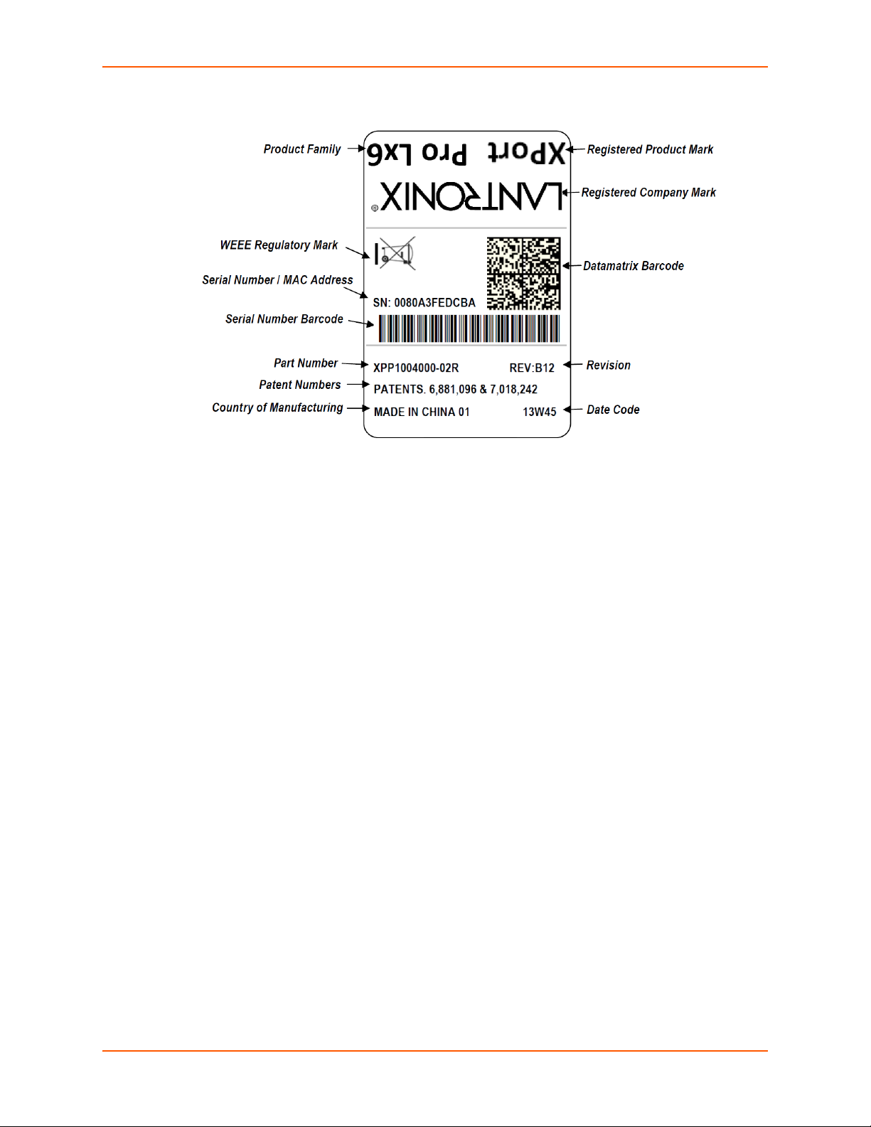
Figure 2-1 XPort Pro Lx6 Product Label
2: Introduction
XPort® Pro Lx6 Embedded Device Server User Guide 15
Page 16

3: Using DeviceInstaller
This chapter covers the steps for locating a XPort Pro Lx6 unit and viewing its properties and
device details. DeviceInstaller application is a free utility program provided by Lantronix that
discovers, configures, upgrades and manages Lantronix device servers.
Notes:
For instructions on using DeviceInstaller to configure the IP address and related
settings or for more advanced features, see the DeviceInstaller Online Help.
Auto IP generates a random IP address in the range of 169.254.0.1 to
169.254.255.254, with a netmask of 255.255.0.0, if no BOOTP or DHCP server is
found. These addresses are not routable.
Accessing XPort Pro Lx6 Using DeviceInstaller
Note: Make note of the MAC address. It may be needed to perform various functions in
DeviceInstaller.
To use the DeviceInstaller utility, first install the latest version from the downloads page on the
Lantronix web site www.lantronix.com/downloads
1. Run the executable to start the installation process and respond to the installation wizard
prompts. (If prompted to select an installation type, select Typical.)
.
2. Click Start -> All Programs -> Lantronix -> DeviceInstaller 4.3 -> DeviceInstaller.
3. When DeviceInstaller starts, it will perform a network device search. To perform another
search, click Search.
4. Expand the XPort folder by clicking the + symbol next to the folder icon. The list of available
Lantronix XPort Pro Lx6 devices appears.
5. Select the XPort Pro Lx6 unit by expanding its entry and clicking on its IP address to view its
configuration.
6. On the right page, click the Device Details tab. The current XPort Pro Lx6 configuration
appears. This is only a subset of the full configuration; the full configuration may be accessed
via Web Manager, CLI or XML.
Device Detail Summary
Note: The settings are Display Only in this table unless otherwise noted
Current Settings Description
Name Shows “XPort Pro Lx6”.
DHCP Device Name
Displays one of the names the XPort Pro Lx6 will send to the DHCP server
if it is configured to obtain an address in this manner.
XPort® Pro Lx6 Embedded Device Server User Guide 16
Page 17

3: Using DeviceInstaller
Current Settings Description
Configurable field. Enter a group to categorize the XPort Pro Lx6. Double-
Group
Comments
Device Family Shows the XPort Pro Lx6 device family type as “XPort”.
Short Name Shows“XPortProLx6“ by default.
Long Name Shows“Lantronix XPort Pro Lx6“ by default.
Type Shows the device type as “XPort Pro Lx6”.
ID Shows the “XPort Pro Lx6“ ID embedded within the unit.
Hardware Address Shows the XPort Pro Lx6 hardware (MAC) address.
Firmware Version Shows the firmware currently installed on the XPort Pro Lx6.
Extended Firmware Version Provides additional information on the firmware version.
Online Status Shows the XPort Pro Lx6 status as Online, Offline, Unreachable (the XPort
IP Address Shows the XPort Pro Lx6 current IPv4 address. To change the IP address,
IP Address was Obtained Appears “Dynamically” if the XPort Pro Lx6 automatically received an IP
Subnet Mask Shows the subnet mask specifying the network segment on which the XPort
Gateway Shows the IP address of the router of this network.
Number of Serial Ports Shows 1, that is, the number of serial ports on the XPort Pro Lx6 embedded
Supports Configurable Pins Shows True, indicating configurable pins are available on the XPort Pro Lx6
Supports Email Triggers Shows True, indicating email triggers are available on the XPort Pro Lx6
Telnet Supported Indicates whether Telnet is enabled on this XPort Pro Lx6 embedded device
Telnet Port Shows the XPort Pro Lx6 port for Telnet sessions.
Web Port Shows the XPort Pro Lx6 port for web sessions.
Firmware Upgradable
click the field, type in the value, and press Enter to complete. This group
name is local to this PC and is not visible on other PCs or laptops using
DeviceInstaller.
Configurable field. Enter comments for the XPort. Double-click the field,
type in the value, and press Enter to complete. This description or comment
is local to this PC and is not visible on other PCs or laptops using
DeviceInstaller.
Pro Lx6 is on a different subnet), or Busy (the XPort Pro Lx6 is currently
performing a task).
click the Assign IP button on the DeviceInstaller menu bar.
address (e.g., from DHCP). Appears “Statically” if the IP address was
configured manually.
If the IP address was assigned dynamically, the following fields appear:
Obtain via DHCP with values of True or False.
Obtain via BOOTP with values of True or False.
Pro Lx6 resides.
There is no default.
device server.
embedded device server.
embedded device server.
server.
Shows True, indicating the XPort Pro Lx6 firmware is upgradable as newer
versions become available.
XPort® Pro Lx6 Embedded Device Server User Guide 17
Page 18

4: Configuration Using Web Manager
This chapter describes how to configure the XPort Pro Lx6 embedded device server using Web
Manager, the Lantronix browser-based configuration tool. The unit’s configuration is stored in nonvolatile memory and is retained without power. All changes take effect immediately, unless
otherwise noted. It contains the following sections:
Accessing Web Manager
Web Manager Components
Navigating Web Manager
Accessing Web Manager
Note: You can also access the Web Manager by selecting the Web Configuration tab on
the DeviceInstaller application window.
To access Web Manager, perform the following steps:
1. Open a standard web browser. Lantronix supports the latest versions of Internet Explorer,
Mozilla Firefox, Safari or Chrome web browsers.
2. Enter the IP address or hostname of the XPort Pro Lx6 in the address bar. The IP address
may have been assigned manually using DeviceInstaller (see the XPort Pro Lx6 Embedded
Device Server Quick Start Guide) or automatically by DHCP.
3. Enter your username and password. The factory-default username is “admin” and “PASS” is
the default password. The Device Status web page displays configurations including network
settings, line settings, tunneling settings, and product information.
XPort® Pro Lx6 Embedded Device Server User Guide 18
Page 19
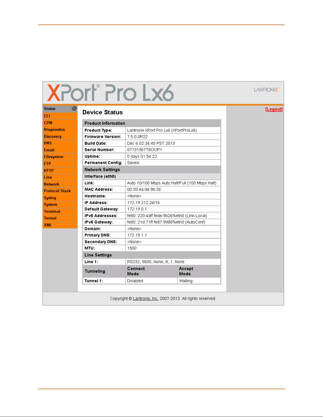
Device Status Page
The Device Status page is the first to appear after you log into Web Manager. The Device Status
page also appears when you click Status in the menu bar in Web Manager.
4: Configuration Using Web Manager
Figure 4-1 Device Status Page
Note: The Logout button is available on any web page. Logging out of the web page
forces re-authentication the next time the web page is accessed.
XPort® Pro Lx6 Embedded Device Server User Guide 19
Page 20
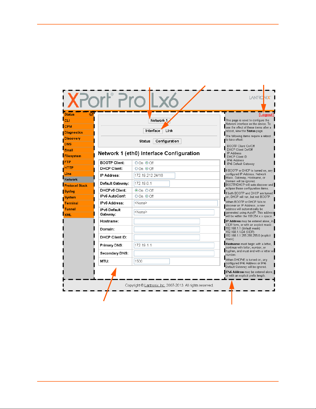
Web Manager Components
Links to
subpages
Items to
configure
Header
Menu
Bar
Configuration and/or Status Area
Footer
Logout
button
Information
and Help Area
The layout of a typical Web Manager page is below.
Figure 4-2 Components of the Web Manager Page
4: Configuration Using Web Manager
XPort® Pro Lx6 Embedded Device Server User Guide 20
Page 21

4: Configuration Using Web Manager
Web Manager pages have these sections:
The menu bar always appears at the left side of the page, regardless of the page shown. The
menu bar lists the names of the pages available in the Web Manager. To bring up a page, click it in
the menu bar.
The main area of the page has these additional sections:
Links near the top of many pages, such as the one in the example above, enable you to link to
additional subpages. On some pages, you must also select the item you are configuring, such
as a tunnel.
In the middle of many pages, you can select or enter new configuration settings. Some pages
show status or statistics in this area rather than allow you to enter settings.
At the bottom of most pages, the current configuration is displayed. In some cases, you can
reset or clear a setting.
The information or help area shows information or instructions associated with the page.
A Logout link is available at the upper right corner of every page. In Chrome or Safari, it is
necessary to close out of the browser to completely logout. If necessary, reopen the browser
to log back in.
The footer appears at the very bottom of the page. It contains copyright information and a link
to the Lantronix home page.
Navigating Web Manager
The Web Manager provides an intuitive point-and-click interface. A menu bar on the left side of
each page provides links you can click to navigate from one page to another. Some pages are
read-only, while others let you change configuration settings.
Note: There may be times when you must reboot the XPort Pro Lx6 for the new
configuration settings to take effect. The chapters that follow indicate when a change
requires a reboot. Anytime you reboot the unit, this operation will take some time to
complete. Please wait a minimum of 25-30 seconds after rebooting the unit before
attempting to make any subsequent connections.
Web Manager Page Description See
Status Shows product information, network, line, and tunneling settings. 19
CLI Shows Command Line Interface (CLI) statistics and lets you change the
current CLI configuration settings.
CPM Shows information about the Configurable Pins Manager (CPM) and how to
set the configurable pins and pin groups to work with a device.
Diagnostics Lets you perform various diagnostic procedures. 53
Table 4-3 Web Manager Pages
Page
60
40
Discovery Shows the query port server state and statistics. 58
DNS Shows the current configuration of the DNS subsystem and the DNS cache. 43
XPort® Pro Lx6 Embedded Device Server User Guide 21
Page 22

4: Configuration Using Web Manager
Web Manager Page
(continued)
Email Shows email statistics and lets you clear the email log, configure email
Filesystem Shows file system statistics and lets you browse the file system to view a file,
FTP Shows statistics and lets you change the current configuration for the File
HTTP Shows HyperText Transfer Protocol (HTTP) statistics and lets you change the
Line Shows statistics and lets you change the current configuration and Command
Network Shows status and lets you configure the network interface. 23
Protocol Stack Lets you perform lower level network stack-specific activities. 50
Syslog Lets you specify the severity of events to log and the server and ports to
System Lets you reboot device, restore factory defaults, upload new firmware, and
Terminal Lets you change current settings for a terminal. 38
Tunnel Lets you change the current configuration settings for an incoming tunnel
XML Lets you export XML configuration and status records, and import XML
Description See
Page
59
settings, and send an email.
48
create a file or directory, upload files using HTTP, copy a file, move a file, or
perform TFTP actions.
44
Transfer Protocol (FTP) server.
45
current configuration and authentication settings.
27
mode settings of a serial line.
44
which the syslog should be sent.
57
change the device long and short names.
29
connection.
61
configuration records.
XPort® Pro Lx6 Embedded Device Server User Guide 22
Page 23

5: Network Settings
The Network Settings show the status of the Ethernet interface/link and let you configure the
settings on the device. Interface settings are related to the configuration of the IP and related
protocols. Link settings are related to the physical link connection, which carries the IP traffic.
Notes:
Some settings require a reboot to take effect. These settings are noted below.
Wait a minimum of 25-30 seconds after rebooting the unit before attempting to make
any subsequent connections.
The blue text in the XML command strings of this chapter are to be replaced with a
user-specified name.
Network Interface Settings
Table 5-1 shows the network interface settings that can be configured. These settings apply to
Ethernet (eth0).
Table 5-1 Network Interface Settings
Network Interface
Settings
BOOTP Client Select to turn On or Off. At boot up, after the physical link is up, the XPort Pro Lx6
DHCP Client Select to turn On or Off. At boot up, after the physical link is up, the XPort Pro Lx6
IP Address Enter the static IPv4 address to use for the interface. You may enter it alone or in
Default Gateway Enter the IPv4 address of the router for this network.
Description
will attempt to obtain IPv4 settings from a BOOTP server.
Note: Overrides the configured IPv4 address/mask, gateway, hostname, and
domain. When DHCP is Enabled, the system automatically uses DHCP,
regardless of whether BOOTP is Enabled. Changing this value requires you to
reboot the device.
will attempt to obtain IPv4 settings from a DHCP server and will periodically renew
these settings with the server.
Note: Overrides BOOTP, the configured IPv4 address/mask, gateway, hostname,
and domain. Changing this value requires you to reboot the device.
Note: Within Web Manager, click Renew to renew the DHCP lease.
CIDR format.
Note: This setting will be used if Static IP is active (both DHCP and BOOTP are
Disabled). Changing this value requires you to reboot the device. When DHCP or
BOOTP is enabled, the XPort Pro Lx6 tries to obtain an IPv4 address from a DHCP
or BOOTP server. If it cannot, the XPort Pro Lx6 generates and uses an Auto IP
address in the range of 169.254.xxx.xxx, with a network mask of 255.255.0.0.
Note: This setting will be used if Static IP is active (both DHCP and BOOTP are
Disabled).
XPort® Pro Lx6 Embedded Device Server User Guide 23
Page 24

5: Network Settings
Network Interface
Description
Settings (continued)
DHCPv6 Client Select to turn On or Off. At bootup, after the physical link is up, the XPort Pro Lx6
will attempt to obtain IPv6 settings from a DHCPv6 server and will periodically
renew these settings with the server.
On: enables the XPort Pro Lx6 server to obtain IPv6 setting from a DHCPv6
server upon bootup.
Off: enables the XPort Pro Lx6 server to obtain IPv4 settings from a DHCP
server upon bootup.
Note: Overrides the configured IP address/mask, gateway, hostname, and
domain. Changing this value requires you to reboot the device. Within Web
Manager, click Renew to renew the DHCPV6 lease.
IPv6 AutoConf Select to turn On or Off.
On: will provide an additional IPv6 addres in addition to the displayed Link Local
IPv6 address and DHCPv6 IPv6 address. This is the auto configuration address
provided by the IPv6 router.
Off: will not display auto configured IPv6 address in CLI or WebUI.
IPv6 Address Enter the static IPv6 address to use for the interface.
Note: This setting is used if Static IPv6 is active (DHCPv6 is Disabled). Changing
this value requires a reboot. When DHCPv6 is enabled, the XPort Pro Lx6 tries to
obtain an IPv6 address from a DHCPv6 server. If it cannot, then XPort Pro Lx6
generates and uses a Link local IPv6 address.
IPv6 Default Gateway Enter the default IPv6 Default Gateway.
Hostname Enter the hostname for the interface. It must begin with a letter or number, continue
with a sequence of letters, numbers, or hyphens, and end with a letter or number.
This setting will take effect immediately, but will not register the hostname with a
DNS server until the next reboot.
Domain Enter the domain name suffix for the interface.
Note: This setting will be used when either Static IP or Auto IP is active, or if
DHCP/BOOTP is active and no Domain Suffix was acquired from the server.
DHCP Client ID Enter the ID if the DHCPV6 server requires a DHCPV6 Client ID option. The
DHCPV6 server’s lease table shows IP addresses and MAC addresses for
devices. The lease table shows the Client ID, in hexadecimal notation, instead of
the XPort Pro Lx6 MAC address.
Primary DNS Enter the IP address of the primary Domain Name Server.
Note: This setting will be used when either Static IP or Auto IP is active, or if
DHCP/BOOTP is active and no DNS server was acquired from the server.
Secondary DNS Enter the IP address of the secondary Domain Name Server.
Note: This setting will be used when either Static IP or Auto IP is active, or if
DHCP/BOOTP is active and no DNS server was acquired from the server.
MTU When DHCP is enabled, the MTU size is (usually) provided with the IP address.
When not provided or using a static configuration, this value is used. The MTU
size can be from 1280 to 1500 bytes, the default being 1500 bytes.
To Configure Network 1 Interface Settings
Using Web Manager
To modify Ethernet (eth0) settings, click Network on the menu and select Network 1 ->
Interface -> Configuration.
XPort® Pro Lx6 Embedded Device Server User Guide 24
Page 25

Using the CLI
To enter the eth0 command level: enable -> config -> if 1
Using XML
Include in your file: <configgroup name="interface" instance="eth0">
To View Network 1 Interface Status
Using Web Manager
In Network Interface Status, you can view both the current operational settings as well as the
settings that would take affect upon a device reboot.
To view Ethernet (eth0) Status, click Network on the menu and select Network 1 ->
Interface -> Status.
Network (Ethernet Network “eth0”) Link Settings
Physical link parameters can be configured for an Ethernet (eth0) Network Interface (see
Table 5-2).
5: Network Settings
Table 5-2 Network 1 (eth0) Link Settings
Network 1 Ethernet (eth0)
Link Settings
Speed Select the Ethernet link speed. (Default is Auto)
Duplex Select the Ethernet link duplex mode. (Default is Auto)
Description
Auto = Auto-negotiation of Link Speed
10 Mbps = Force 10 Mbps
100 Mbps = Force 100 Mbps
Auto = Auto-negotiation of Link Duplex
Half = Force Half Duplex
Full = Force Full Duplex
Notes:
When speed is Auto, duplex must be Auto or Half.
When speed is not Auto, duplex must be Half or Full.
Fixed speed Full duplex will produce errors connected to Auto, due to duplex
mismatch.
XPort® Pro Lx6 Embedded Device Server User Guide 25
Page 26

5: Network Settings
To Configure Network 1 Link Settings
Using Web Manager
To modify Ethernet (eth0) Link information, click Network on the menu and select Network 1
> Link > Configuration.
Using the CLI
To enter the eth0 Link command level: enable -> config -> if 1 -> link
Using XML
Include in your file: <configgroup name="ethernet" instance="eth0">
XPort® Pro Lx6 Embedded Device Server User Guide 26
Page 27

6: Line and Tunnel Settings
The XPort Pro Lx6 embedded device server contains one line using a standard RS232/RS485
serial port. This line may be configured to operate in the following modes:
RS232
RS485 Full Duplex (also compatible with RS-422)
RS485 Half Duplex, with and without termination impedance
All serial settings such as Baud Rate, Parity, Data Bits, etc, apply to these lines.
Line Settings
The Line Settings allow configuration of the serial lines (ports).
Some settings may be specific to only certain lines. Such settings are noted below.
Table 6-1 Line Configuration Settings
Line Settings Description
Name Enter a name or short description for the line, if desired. By default, there is
no name specified. A name that contains white space must be quoted.
Interface Set the interface type for the Line. The default is RS232 for Line 1.
Choices are:
RS232
RS485 Full-Duplex
RS485 Half-Duplex
Termination Select to Enable or Disable Line Termination. The default is Disable.
Note: This setting is only relevant for Line 1 with Interface type RS485 Half-
Duplex.
State Select to Enable or Disable the operational state of the Line. The default is
Enable.
Protocol Set the operational protocol for the Line. The default is Tunnel. Choices are:
None
Tunnel = Serial-Network tunneling protocol.
Baud Rate Set the Baud Rate (speed) of the Line. The default is 9600.
Any set speed between 300 and 921600 may be selected: 300, 600, 1200,
2400, 4800, 9600, 19200, 38400, 57600, 115200, 230400, 921600. When
selecting a Custom baud rate, you may manually enter any value between
300 and 921600.
Note: Custom baud rates are not supported when a line is configured for
Command Mode.
Parity Set the Parity of the Line. The default is None.
Data Bits Set the number of data bits for the Line. The default is 8.
Stop Bits Set the number of stop bits for the Line. The default is 1.
Flow Control Set the flow control for the Line. The default is None.
XPort® Pro Lx6 Embedded Device Server User Guide 27
Page 28

6: Line and Tunnel Settings
Line Settings Description
Xon Char Set Xon Char to be used when Flow Control is set to Software. Prefix decimal
with \ or prefix hexadecimal with 0x or prefix a single control character
<control>.
Xoff Char Set Xoff Char to be used when Flow Control is set to Software. Prefix decimal
with \ or prefix hexadecimal with 0x or prefix a single control character
<control>.
Gap Timer Set the Gap Timer delay to Set the number of milliseconds to pass from the
last character received before the driver forwards the received serial bytes.
By default, the delay is four character periods at the current baud rate
(minimum 1 msec). Gap Timer range is 1 to 5000 milliseconds (default value
is 4000 msec).
Threshold Set the number of threshold bytes which need to be received in order for the
driver to forward received characters. Default value is 56 bytes.
Table 6-2 Line Command Mode Settings
Line Command
Mode Settings
Mode Set the Command Mode state of the Line. When in Command Mode, a CLI session
Wait Time Enter the amount of time to wait during boot time for the Serial String. This timer
Serial String Enter the Text or Binary string of bytes that must be read on the Serial Line during
Echo Serial String Select Enable or Disable for Echo Serial String. Applies only if mode is “User Serial
Signon Message Enter the string of bytes to be sent to the Serial Line during boot time. It may contain
Description
operates exclusively on the Line. Choices are:
Always
Use Serial String
Disabled
Note: In order to enable Command Mode on the Line, Tunneling on the Line must
be Disabled (both Connect and Accept modes). Also, custom baud rates are not
supported in Command Mode.
starts right after the Signon Message has been set on the Serial Line and applies
only if mode is “Use Serial String”.
boot time in order to enable Command Mode. It may contain a time element to
specify a required delay in milliseconds x, formed as {x}. Applies only if mode is
“User Serial String”. It may contain a binary character(s) of the form [x]. For
example, use decimal [12] or hex [0xc].
String”. Select enable to echo received characters backed out on the line while
looking for the serial string.
a binary character(s) of the form [x]. For example, use decimal [12] or hex [0xc].
To Configure Line Settings
The following section describes the steps to view and configure Line 1 settings; these steps apply to other line instances of the device.
Using Web Manager
To configure a specific line, click Line in the menu and select Line 1 -> Configuration (Table
6-1).
XPort® Pro Lx6 Embedded Device Server User Guide 28
Page 29

6: Line and Tunnel Settings
To configure a specific line in Command Mode, click Line in the menu and select Line 1 ->
Command Mode (Table 6-2).
Using the CLI
To enter Line 1 command level: enable -> line 1
Using XML
Include in your file: <configgroup name="line" instance="1">
Include in your file: <configgroup name="serial command mode" instance="1">
To View Line Statistics
Using Web Manager
To view statistics for Line 1, click Line in the menu and select Line 1 -> Statistics.
Using the CLI
To view Line statistics: enable -> line 1, show statistics
Using XML
Include in your file: <statusgroup name=”line” instance=”1”>
Tunnel Settings
Tunneling allows serial devices to communicate over a network, without “being aware” of the
devices which establish the network connection between them. Tunneling parameters are
configured using the Tunnel menu and submenus. The Tunnel settings allow you to configure
how the Serial-Network tunneling operates. Tunneling is available on all serial lines. The
connections on one serial line are separate from those on another serial port.
Notes: The following section describes the steps to view and configure Tunnel 1 settings;
these steps apply to other tunnel instances of the device.
Tunnel Settings
Serial Settings
These serial settings for the tunnel apply to the Serial Line interface. The Line Settings and
Protocol are displayed for informational purposes and must be configured from the Line settings.
XPort® Pro Lx6 Embedded Device Server User Guide 29
Page 30

Table 6-3 Tunnel Serial Settings
6: Line and Tunnel Settings
Tunnel Serial
Description
Settings
Line Settings Line Settings information here is display only. Go to the section, To Configure
Line Settings to modify these settings.
Protocol Protocol information here is display only. Go to the section, To Configure
Line Settings to modify these settings.
DTR Select the conditions in which the Data Terminal Ready (DTR) control signal
on the serial line are asserted. Choices are:
Unasserted
TruPort = the DTR is asserted whenever either a connect or an accept
mode tunnel connection is active with the Telnet Protocol RFC2217 saying
that the remote DSR is asserted.
Asserted while connected = the DTR is asserted whenever either a
connect or an accept mode tunnel connection is active.
Continuously asserted
To Configure Tunnel Serial Settings
Using Web Manager
To configure the Serial Settings for a specific tunnel, click Tunnel in the menu and select
Tunnel 1 -> Serial Settings.
Using the CLI
To enter Tunnel 1 command level: enable -> tunnel 1 -> serial
Using XML
Include in your file: <configgroup name=”tunnel serial” instance=”1”>
Packing Mode
With Packing, data from the serial Line is not sent over the network immediately. Instead, data is
queued and sent in segments, when either the timeout or byte threshold is reached. Packing
applies to both Accept and Connect Modes.
Table 6-4 Tunnel Packing Mode Settings
Tunnel Packing Mode
Settings
Mode Configure the Tunnel Packing Mode. Choices are:
Threshold Set the threshold (byte count). If the received serial data reaches this
Description
Disable = Data not packed.
Timeout = data sent after timeout occurs.
Send Character = data sent when the Send Character is read on the Serial
Line.
threshold, then the data will be sent on the network. Valid range is 100 to
1450 bytes. Default is 512.
XPort® Pro Lx6 Embedded Device Server User Guide 30
Page 31

6: Line and Tunnel Settings
Tunnel Packing Mode
Settings (continued)
Timeout Set the timeout value, in milliseconds, after the first character is received on
Send Character Enter Control Characters in any of the following forms:
Trailing Character Enter Control Characters in any of the following forms:
Description
the serial line, before data is sent on the network. Valid range is 1 to 30000
milliseconds. Default is 1000.
<control>J
0xA (hexadecimal)
\10 (decimal)
If used, the Send Character is a single printable character or a control
character that, when read on the Serial Line, forces the queued data to be
sent on the network immediately.
<control>J
0xA (hexadecimal)
\10 (decimal).
If used, the Trailing Character is a single printable character or a control
character that is injected into the outgoing data stream right after the Send
Character. Disable the Trailing Character by blanking the field (setting it to
<None>).
To Configure Tunnel Packing Mode Settings
Using Web Manager
To configure the Packing Mode for a specific tunnel, click Tunnel in the menu and select
Tunnel 1 -> Packing Mode.
Using the CLI
To enter the Tunnel 1 Packing command level: enable -> tunnel 1 -> packing
Using XML
Include in your file: <configgroup name="tunnel packing" instance="1">
Accept Mode
In Accept Mode, the XPort Pro Lx6 listens (waits) for incoming connections from the network. A
remote node on the network initiates the connection.
The configurable local port is the port the remote device connects to for this connection. There is
no remote port or address. Supported serial lines and associated local port numbers progress
sequentially in matching value. For instance, the default local port is 10001 for serial line 1.
Serial data can still be received while waiting for a network connection, keeping in mind serial data
buffer limitations.
XPort® Pro Lx6 Embedded Device Server User Guide 31
Page 32

Table 6-5 Tunnel Accept Mode Settings
6: Line and Tunnel Settings
Tunnel Accept Mode
Description
Settings
Mode Set the method used to start a tunnel in Accept mode. Choices are:
Disable = do not accept an incoming connection.
Always = accept an incoming connection (default).
Any Character = start waiting for an incoming connection when any
character is read on the serial line.
Start Character = start waiting for an incoming connection when the
start character for the selected tunnel is read on the serial line.
Modem Control Asserted = start waiting for an incoming connection as
long as the Modem Control pin (DSR) is asserted on the serial line until
a connection is made.
Modem Emulation = start waiting for an incoming connection when
triggered by modem emulation AT commands. Connect mode must
also be set to Modem Emulation.
Local Port Set the port number for use as the network local port. The default local port
number for each supported serial line number progresses sequentially in
equal value so that Tunnel X : 1000X. For example:
Tunnel 1 : 10001
Tunnel 2 : 10002
Protocol Select the protocol type for use with Accept Mode:
TCP (default protocol)
TCP AES
Telnet
TCP Keep Alive Enter the time, in milliseconds, the XPort Pro Lx6 waits during a silent TCP
connection before checking if the currently connected network device is
still on the network. If the unit gets no response after 1 attempt, it drops
the connection. Enter 0 to disable.
Flush Serial Set whether the serial line data buffer is flushed upon a new network
connection. Choices are:
Enabled = serial data buffer is flushed on network connection
Disabled = serial data buffer is not flushed on network connection
(default)
Block Serial Set whether Block Serial is enabled for debugging purposes. Choices are:
Enabled = if Enabled, incoming characters from the serial line will not
be forwarded to the network. Instead, they will be buffered and will
eventually flow off the serial line if hardware or software flow control is
configured.
Disabled = this is the default setting; incoming characters from the
Serial Line are sent on into the network. Any buffered characters are
sent first.
Block Network Set whether Block Network is enabled for debugging purposes. Choices
are:
Enabled = if Enabled, incoming characters from the network will not be
forwarded to the Serial Line. Instead, they will be buffered and will
eventually flow off the network side.
Disabled = this is the default setting; incoming characters from the
network are sent on into the Serial Line. Any buffered characters are
sent first.
XPort® Pro Lx6 Embedded Device Server User Guide 32
Page 33

6: Line and Tunnel Settings
Tunnel Accept Mode
Settings (continued)
Password Enter a password. This password can be up to 31 characters in length and
Prompt for Password Select Enabled or Disabled (to enable or disable). This option will only
Email on Connect Select an email profile number to which an email notification will be sent
Email on Disconnect Select an email profile number to which an email notification will be sent
CP Output Enter the CP Output Group whose value should change when a
Description
must contain only alphanumeric characters and punctuation. When set,
clients must send the correct password string to the unit within 30 seconds
from opening network connection in order to enable data transmission.
The password sent to the unit must be terminated with one of the following:
0A (Line Feed)
00 (Null)
0D 0A (Carriage Return/Line Feed)
0D 00 (Carriage Return/Null)
If, Prompt for Password is set to Enabled and a password is provided,
the user will be prompted for the password upon connection.
appear if a password is specified above.
upon the establishment of an accept mode tunnel.
upon the disconnection of an accept mode tunnel.
connection is established and dropped. Connection Value specifies the
value to set the CP Group to when a connection is established.
Disconnection Value specifies the value to set the CP Group to when the
connection is closed. To display the “Connection Value” and
“Disconnection Value”, first enter a “CP Output Group”, then click outside
that field.
To Configure Tunnel Accept Mode Settings
Using Web Manager
To configure the Accept Mode for a specific tunnel, click Tunnel in the menu and select
Tunnel 1 -> Accept Mode.
Using the CLI
To enter Tunnel 1 Accept Mode command level: enable -> tunnel 1 -> accept
Using XML
Include in your file: <configgroup name="tunnel accept" instance="1">
Connect Mode
In Connect Mode, the XPort Pro Lx6 continues to attempt an outgoing connection on the network,
until established. If the connection attempt fails or the connection drops, then it retries after a
timeout. The remote node on the network must listen for the Connect Mode’s connection.
For Connect Mode to function, it must be enabled, have a remote station (node) configured, and a
remote port configured (TCP or UDP). When established, Connect Mode is always on. Enter the
remote station as an IPv4 or IPv6 address or DNS name. The XPort Pro Lx6 will not make a
connection unless it can resolve the address.
XPort® Pro Lx6 Embedded Device Server User Guide 33
Page 34

6: Line and Tunnel Settings
For Connect Mode using UDP, the XPort Pro Lx6 accepts packets from any device on the
network. It will send packets to the last device that sent it packets.
Note: The Port in Connect Mode is not the same port configured in Accept Mode.
The TCP keepalive time is the time in which probes are periodically sent to the other end of the
connection. This ensures the other side is still connected.
Table 6-6 Tunnel Connect Mode Settings
Tunnel Connect Mode
Description
Settings
Mode Set the method to be used to attempt a connection to a remote host or device.
Choices are:
Disable = an outgoing connection is never attempted. (default)
Always = a connection is attempted until one is made. If the connection gets
disconnected, the device XPort Pro Lx6 retries until it makes a connection.
Any Character = a connection is attempted when any character is read on
the serial line.
Start Character = a connection is attempted when the start character for the
selected tunnel is read on the serial line.
Modem Control Asserted = a connection is attempted as long as the
Modem Control pin (DSR) is asserted, until a connection is made.
Modem Emulation = a connection is attempted when triggered by modem
emulation AT commands.
Local Port Enter an alternative Local Port. The Local Port is set to <Random> by default
but can be overridden. Blank the field to restore the default.
Host 1 Click on the displayed information to expand it for editing. If <None> is
displayed, clicking it will allow you to configure a new host. At least one Host is
required to enable Connect Mode as this information is necessary to connect to
that host.
Reconnect Timer Set the value of the reconnect timeout (in milliseconds) for outgoing connections
established by the device. Valid range is 1 to 65535 milliseconds. Default is
15000.
Flush Serial Data Set whether the serial Line data buffer is flushed upon a new network
connection. Choices are:
Enabled = serial data buffer is flushed on network connection
Disabled = serial data buffer is not flushed on network connection (default)
Block Serial Set whether Block Serial is enabled for debugging purposes. Choices are:
Enabled = If Enabled, incoming characters from the Serial Line will not be
forwarded to the network. Instead, they will be buffered and will eventually
flow off the Serial Line if hardware or software flow control is configured.
Disabled = this is the default setting; incoming characters from the Serial Line
are sent on into the network. Any buffered characters are sent first.
Block Network Set whether Block Network is enabled for debugging purposes. Choices are:
Enabled = If Enabled, incoming characters from the network will not be
forwarded to the Serial Line. Instead, they will be buffered and will eventually
flow off the network side.
Disabled = this is the default setting; incoming characters from the network
are sent on into the Serial Line. Any buffered characters are sent first.
Email on Connect Select an email profile number to which an email notification will be sent upon
the establishment of an accept mode tunnel.
XPort® Pro Lx6 Embedded Device Server User Guide 34
Page 35

6: Line and Tunnel Settings
Tunnel Connect Mode
Settings (continued)
Email on Disconnect Select an email profile number to which an email notification will be sent upon
CP Output Enter the CP Output Group whose value should change when a connection is
Description
the disconnection of an accept mode tunnel.
established and dropped. Connection Value specifies the value to set the CP
Group to when a connection is established. Disconnection Value specifies the
value to set the CP Group to when the connection is closed. To display the
“Connection Value” and “Disconnection Value”, first enter a “CP Output Group”,
then click outside that field.
To Configure Tunnel Connect Mode Settings
Using Web Manager
To configure the Connect Mode for a specific tunnel, click Tunnel in the menu and select
Tunnel 1 -> Connect Mode.
Using the CLI
To enter the Tunnel 1 Connect Mode command level: enable -> tunnel 1 -> connect
Using XML
Include in your file: <configgroup name="tunnel connect" instance="1">
Disconnect Mode
Specifies the optional conditions for disconnecting any Accept Mode or Connect Mode connection
that may be established. If any of these conditions are selected but do not occur and the network
disconnects to the device, a Connect Mode connection will attempt to reconnect. However, if none
of these conditions are selected, a closure from the network is taken as a disconnect.
Table 6-7 Tunnel Disconnect Mode Settings
Tunnel Disconnect
Mode Settings
Stop Character Enter the Stop Character which when received on the Serial Line, disconnects the
Modem Control Set whether Modem Control enables disconnect when the Modem Control pin is not
Timeout Enter the number of milliseconds a tunnel may be idle before disconnection. The
Flush Serial Data Set whether to flush the Serial Line when the Tunnel is disconnected. Choices are:
Description
tunnel. The Stop Character may be designated as a single printable character or
as a control character. Control characters may be input in any of the following
forms: <control>J or 0xA(hexadercimal) or \10 (decimal). Disable the Stop
Character by blanking the field to set it to <None>.
asserted on the Serial Line. Choices are:
Enabled
Disabled (default)
value of zero disables the idle timeout.
Enabled
Disabled (default)
XPort® Pro Lx6 Embedded Device Server User Guide 35
Page 36

6: Line and Tunnel Settings
To Configure Tunnel Disconnect Mode Settings
Using Web Manager
To configure the Disconnect Mode for a specific tunnel, click Tunnel in the menu and select
Tunnel 1 -> Disconnect Mode.
Using the CLI
To enter the Tunnel 1 Disconnect command level: enable -> tunnel 1 -> disconnect
Using XML
Include in your file: <configgroup name=”tunnel disconnect” instance=”1”>
Modem Emulation
Some older equipment is designed to attach to a serial port and dial into a network with a modem.
This equipment uses AT commands to control the connection. For compatibility with these older
devices on modern networks, our product mimics the behavior of the modem.
Table 6-8 Tunnel Modem Emulation Settings
Tunnel Modem
Emulation Settings
Echo Pluses Set whether the pluses will be echoed back during a “pause +++ pause” escape
Echo Commands Set whether characters read on the Serial Line will be echoed, while the Line is in
Verbose Response Set whether Modem Response Codes are sent out on the Serial Line. Choices are:
Response Type Select a representation for the Modem Response Codes sent out on the Serial
Error Unknown
Commands
Incoming Connection Set how and if requests are answered after an incoming RING (ATS0=2). Choices
Description
sequence on the Serial Line. Choices are:
Enabled
Disabled (default)
Modem Command Mode. Choices are:
Enabled
Disabled
Enabled
Disabled
Line. Choices are:
Text (ATV1) (default)
Numeric (ATV0)
Set whether the Error Unknown Commands is enabled (ATU0) and ERROR is
returned on the Serial Line for unrecognized AT commands. OTherwise (ATU1)
OK is returned for unrecognized AT commands. Choices are:
Enabled
Disabled (default)
are:
Disabled (default)
Automatic
Manual
XPort® Pro Lx6 Embedded Device Server User Guide 36
Page 37

6: Line and Tunnel Settings
Tunnel Modem
Emulation Settings
Connect String Enter the customized Connect String sent to the Serial Line with the Connect
Display Remote IP Set whether the Display Remote IP is enabled so that the incoming RING sent on
Description
Modem Response Code.
the Serial Line is followed by the IP address of the caller. Choices are:
Enabled
Disabled (default)
To Configure Tunnel Modem Emulation Settings
Using Web Manager
To configure the Modem Emulation for a specific tunnel, click Tunnel in the menu and select
Tunnel 1 -> Modem Emulation.
Using the CLI
To enter the Tunnel 1 Modem command level: enable -> tunnel 1 -> modem
Using XML
Include in your file: <configgroup name=”tunnel modem” instance=”1”>
Statistics
Tunnel statistics contains data counters, error counters, connection time and connection
information. Statistics are available at each individual connection and aggregated across all
connections.
To View Tunnel Statistics
Using Web Manager
To view statistics for a specific tunnel, click Tunnel in the menu and select the Tunnel 1 ->
Statistics.
Using the CLI
To view Tunnel 1 statistics: enable -> tunnel 1, show statistics
Using XML
Include in your file: <statusgroup name=”tunnel” instance=”1”>
XPort® Pro Lx6 Embedded Device Server User Guide 37
Page 38

7: Terminal and Host Settings
Predefined connections are available via Telnet or a serial port. A user can choose one of the
presented options and the device automatically makes the predefined connection.
Either the Telnet or serial port connection can present the CLI or the Login Connect Menu. By
default, the CLI is presented when the device is accessed. When configured to present the Login
Connect Menu, the hosts configured via the Host selections, and named serial lines are
presented.
Terminal Settings
You can configure whether each serial line or the Telnet server presents a CLI or a Login Connect
menu when a connection is made.
Table 7-1 Terminal on Network and Line Settings
Terminal on Network
and Line Settings
Terminal Type Enter text to describe the type of terminal. The text will be sent to a host via IAC.
Login Connect Menu Select the interface to display when the user logs in. Choices are:
Exit Connect Menu Select whether to display a choice for the user to exit the Login Connect Menu
Send Break Enter a Send Break control character, e.g., <control> Y, or blank to disable.
Break Duration Enter how long the break should last in milliseconds, up to 10000. Default is
Echo Select whether to enable echo:
Description
Note: IAC means, “interpret as command.” It is a way to send commands over
the network such as send break or start echoing.
Enabled = shows the Login Connect Menu.
Disabled = shows the CLI (default)
and reach the CLI. Choices are:
Enabled = a choice allows the user to exit to the CLI.
Disabled = there is no exit to the CLI (default)
When the Send Break control character is received from the network on its way
to the serial line, it is not sent to the line; instead, the line output is forced to be
inactive (the break condition).
Note: This configuration option is only available for Line Terminals.
500.
Note: This configuration option is only available for Line Terminals.
Enabled
Disabled
Note: Applies only to Connect Mode Telnet connections, not to Accept Mode.
Only disable Echo if your terminal echoes, in which case you will see double of
each character typed. Default is enabled.
XPort® Pro Lx6 Embedded Device Server User Guide 38
Page 39

7: Terminal and Host Settings
To Configure the Terminal Network Connection
Using Web Manager
To configure the Terminal on Network, click Terminal on the menu and select Network ->
Configuration.
To configure the Terminal on Network, click Line 1 on the menu and select Network ->
Configuration.
To configure the Terminal on Network, click Line 2 on the menu and select Network ->
Configuration.
Using the CLI
To enter the Terminal Network command level: enable -> config -> terminal
network
Using XML
Include in your file: <configgroup name=”terminal” instance=”network”>
To Configure the Terminal Line Connection
Note: The following section describes the steps to view and configure Terminal 1
settings; these steps apply to other terminal instances of the device.
Using Web Manager
To configure a particular Terminal Line, click Terminal on the menu and select Line 1 ->
Configuration.
Using the CLI
To enter the Terminal Line command level: enable -> config -> terminal 1
Using XML
Include in your file: <configgroup name=”terminal” instance=”1”>
XPort® Pro Lx6 Embedded Device Server User Guide 39
Page 40

8: Configurable Pin Manager
The Configurable Pin Manager is responsible for assignment and control of the configurable pins
(CPs) available on the XPort Pro Lx6 embedded device service. There are three configurable pins
on the XPort Pro Lx6.
You must configure the CPs by making them part of a group. A CP Group may consist of one or
more CPs. This increases flexibility when incorporating the XPort Pro Lx6 into another system.
Note: The blue text in the XML command strings of this chapter are to be replaced with
a user-specified name.
CPM: Configurable Pins
Each CP is associated with an external hardware pin. CPs can trigger an outside event, like
sending an email message or starting Command Mode on a serial Line.
The Current Configuration table shows the current settings for each CP.
Table 8-1 Current Configurable Pins
CP Ref Configured as Value Groups Active in group
CP1 Pin 14 Input 1 2 <available>
CP2 Pin 16 Input 1 0 <available>
CP3 Pin 18 Input 0 2 <available>
Table 8-2 CP Status
CPM – CPs Status Description
Name
State
Type Shows the CP hardware pin type. Can be updated. Choices are:
Value Shows the last bit in the CP current value.
Bit
Level
I/O
Logic
Shows the CP number.
Shows the current enable state of the CP.
Input
Output
When a CP is configured as output, it can be toggled by setting the value.
Whatever value is given, the first bit 0 is used as the setting. 1 means asserted
and 0 means de-asserted. Additionally, the CP logic can be inverted so that
assertion is low.
Visual display of the bitwise 32 bit placeholders for a CP.
A “+” symbol indicates the CP is asserted (the voltage is high). A “-“indicates the
CP voltage is low.
Indicates the current status of the pin:
I = input
O = output
<blank> = unassigned
An “I” indicates the CP is inverted (active low).
XPort® Pro Lx6 Embedded Device Server User Guide 40
Page 41

8: Configurable Pin Manager
CPM – CPs Status Description
Binary
CP#
Groups
Shows the binary assertion value of the corresponding bit.
Shows the CP number.
Lists the groups in which the CP is a member.
Notes:
To modify a CP, all groups in which it is a member must be disabled.
The changes to a CP configuration are not saved in FLASH. Instead, these CP
settings are used when the CP is added to a CP Group. When the CP Group is
saved, its CP settings are saved with it. Thus, a particular CP may be defined as
"Input" in one group but as "Output" in another. Only one group containing any
particular CP may be enabled at once.
CPM: Groups
The CP Groups settings allow for the management of CP groups. Groups can be created or
deleted. CPs can be added to or removed from groups. A group, based on its state, can trigger
outside events (such as sending email messages). Only an enabled group can be a trigger.
Table 8-3 CPM Group Current Configuration
CPM – Groups Current
Configuration
Group Name Shows the CP group’s name.
State Indicates whether the group is enabled or disabled.
CP Info Shows the number of CPs assigned to the group.
Description
Table 8-4 CPM Group Status
CPM – Groups Group
Status
Name Shows the CP Group name.
State Current enable state of the CP group.
Value Shows the CP group’s current value or shows “Disabled” if the group is
Bit Visual display of the bit placeholders for a CP.
Level A “+” symbol indicates the CP’s bit position is asserted (the voltage is high).
I/O Indicates the current status of the pin:
Logic An “I” indicates the CP output is inverted.
Binary Shows the assertion value of the corresponding bit.
CP# Shows the configurable pin number and its bit position in the CP group.
Description
disabled.
A “-“ indicates the CP voltage is low.
I = input
O = output
<blank> = unassigned
X = group is disabled or bit is unassigned in group
XPort® Pro Lx6 Embedded Device Server User Guide 41
Page 42

8: Configurable Pin Manager
To Configure CPM Settings
Using Web Manager
To configure a configurable pin, click CPM in the menu, select CPs and then the desired CP
to configure.
To configure a CPM Group, click CPM in the menu, select Groups and then the desired
Group Name to configure.
Using the CLI
To enter the CPM command level: enable -> cpm
Using XML
Include in your file: <configgroup name=”cp group” instance=”group name”>
Include in your file: <configitem name=”cp” instance=”cp number”>
XPort® Pro Lx6 Embedded Device Server User Guide 42
Page 43

9: Services Settings
DNS Settings
This section describes the active run-time settings for the domain name system (DNS) protocol.
The primary and secondary DNS addresses come from the active interface. The static addresses
from the Network Interface configuration settings may be overridden by DHCP.
Note: The blue text in the XML command strings of this chapter are to be replaced with
a user-specified name.
Setting / Field Description
Lookup Perform one of the following and click Lookup:
Enter either an IPv4 or IPv6 address and perform a reverse Lookup to locate the
hostname for that IP address.
Enter a hostname, and perform a forward Lookup to locate the corresponding IP
address
IPv6 Precedence Select to specify IPv6 or IPv4 precedence:
Enabled: When enabled, IPv6 DNS records will take precedence over IPv4
records when connecting to a host.
Disabled: When disabled, IPv4 DNS records will take precednce over IPv6
DNS when connecting to a host. This is the default setting.
Table 9-1 DNS Settings
To View or Configure DNS Settings:
Using Web Manager
To view DNS current status, click DNS in the menu and select Status.
To lookup DNS name or IP address, click DNS in the menu, select Status, and enter an IP
address or hostname in the Lookup field.
To set IPv6 precedence, click DNS in the menu and select Configuration.
Note: To configure DNS for cases where it is not supplied by a protocol, click Network
in the menu and select Interface -> Configuration.
Using the CLI
To enter the DNS command level: enable -> dns
Using XML
Include in your file: <configgroup name=”interface” instance=”eth0”>
XPort® Pro Lx6 Embedded Device Server User Guide 43
Page 44

FTP Settings
The FTP protocol can be used to upload and download user files, and upgrade the XPort Pro Lx6
firmware. A configurable option is provided to enable or disable access via this protocol.
FTP Settings Description
State Select to enable or disable the FTP server:
To Configure FTP Settings
Using Web Manager
To configure FTP, click FTP in the menu.
Using the CLI
9: Services Settings
Table 9-2 FTP Settings
Enabled (default)
Disabled
To enter the FTP command level: enable -> config -> ftp
Using XML
Include in your file: <configgroup name=”ftp server”>
Syslog Settings
The Syslog information shows the current configuration and statistics of the syslog. Here you can
configure the syslog host and the severity of the events to log.
Note: The system log is always saved to local storage, but it is not retained through
reboots unless diagnostics logging to the filesystem is enabled. Saving the system log to a
server that supports remote logging services (see RFC 3164) allows the administrator to
save the complete system log history. The default port is 514.
Syslog Settings Description
State Select to enable or disable the syslog:
Host Enter the IP address of the remote server to which system logs are sent for storage.
Remote Port Enter the number of the port on the remote server that supports logging services.
Table 9-3 Syslog Settings
Enabled
Disabled (default)
The default is 514.
XPort® Pro Lx6 Embedded Device Server User Guide 44
Page 45

9: Services Settings
Syslog Settings
(continued)
Severity Log Level Specify the minimum level of system message the XPort Pro Lx6 should log. This
To View or Configure Syslog Settings
Using Web Manager
To configure the Syslog, click Syslog in the menu.
Using the CLI
To enter the Syslog command level: enable -> config -> syslog
Using XML
Include in your file: <configgroup name=”syslog”>
HTTP Settings
Hypertext Transfer Protocol (HTTP) is the transport protocol for communicating hypertext
documents on the Internet. HTTP defines how messages are formatted and transmitted. It also
defines the actions web servers and browsers should take in response to different commands.
HTTP Authentication enables the requirement of usernames and passwords for access to the
device.
Description
setting applies to all syslog facilities. The drop-down list in the Web Manager is in
descending order of severity (e.g., Emergency is more severe than Alert.)
Table 9-4 HTTP Settings
HTTP Settings Description
State Select to enable or disable the HTTP server:
Enabled (default)
Disabled
Port Enter the port for the HTTP server to use. The default is 80.
Max Timeout Enter the maximum time for the HTTP server to wait when receiving a
request. This prevents Denial-of-Service (DoS) attacks. The default is 10
seconds.
Max Bytes Enter the maximum number of bytes the HTTP server accepts when receiving
a request. The default is 65536 KB which prevents DoS attacks. The range
varies from 2048 to 65536.
Note: You may need to increase this number in some cases where the
browser is sending data aggressively within TCP windows size limit, when file
(including firmware upgrade) is uploaded from webpage.
Logging State Select to enable or disable HTTP server logging:
Enabled (default)
Disabled
Max Log Entries Set the maximum number of HTTP server log entries. Only the last Max Log
Entries are cached and viewable.
XPort® Pro Lx6 Embedded Device Server User Guide 45
Page 46

9: Services Settings
HTTP Settings (continued) Description
Log Format Set the log format string for the HTTP server. Follow these Log Format rules:
%a - remote IP address (could be a proxy)
%b - bytes sent excluding headers
%B - bytes sent excluding headers (0 = '-')
%h - remote host (same as '%a')
%{h}i - header contents from request (h = header string)
%m - request method
%p - ephemeral local port value used for request
%q - query string (prepend with '?' or empty '-')
%t - timestamp HH:MM:SS (same as Apache '%(%H:%M:%S)t' or
'%(%T)t')
%u - remote user (could be bogus for 401 status)
%U - URL path info
%r - first line of request (same as '%m %U%q <version>')
%s - return status
Authentication Timeout The timeout period applies if the selected authentication type is Digest. After
this period of inactivity, the client must authenticate again.
To Configure HTTP Settings
Using Web Manager
To configure HTTP settings, click HTTP in the menu and select Configuration.
To view HTTP statistics, click HTTP in the menu and select Statistics.
Using the CLI
To enter the HTTP command level: enable -> config -> http
Using XML
Include in your file: <configgroup name=”http server”>
Table 9-5 HTTP Authentication Settings
HTTP Authentication
Settings
URI Enter the Uniform Resource Identifier (URI).
Auth Type Select the authentication type:
Description
Note: The URI must begin with ‘/’ to refer to the filesystem.
None: no authentication is necessary.
Basic: encodes passwords using Base64.
Digest : encodes passwords using MD5.
To Configure HTTP Authentication
Using Web Manager
To configure HTTP Authentication, click HTTP in the menu and select Authentication.
XPort® Pro Lx6 Embedded Device Server User Guide 46
Page 47

9: Services Settings
Using the CLI
To enter the HTTP command level: enable -> config -> http
Using XML
Include in your file: <configgroup name=”http authentication uri”
instance=”uri name”>
XPort® Pro Lx6 Embedded Device Server User Guide 47
Page 48

10: Maintenance and Diagnostics Settings
Filesystem Settings
Use the file system to list, view, create, upload, copy, move, remove, and transfer files. The XPort
Pro Lx6 embedded device server uses a flash file system to store files.
File Display
It is possible to view the list of existing files, and to view their contents in the ASCII or hexadecimal
formats.
Table 10-1 File Display Settings
File Display Commands Description
ls Displays a list of files on the XPort Pro Lx6, and their respective sizes.
cat Displays the specified file in ASCII format.
dump Displays the specified file in a combination of hexadecimal and ASCII
formats.
pwd Print working directory.
cd Change directories.
show tree Display file/directory tree.
To Display Files
Using Web Manager
To view existing files and file contents, click FIlesystem in the menu and select Browse.
Using the CLI
To enter the Filesystem command level: enable -> filesystem
Using XML
Not applicable.
XPort® Pro Lx6 Embedded Device Server User Guide 48
Page 49

10: Maintenance and Diagnostics Settings
File Modification
The XPort Pro Lx6 allows for the creation and removal of files on its filesystem.
Table 10-2 File Modification Settings
File Modification
Commands
rm Removes the specified file from the file system.
touch Creates the specified file as an empty file.
cp Creates a copy of a file.
mkdir Creates a directory on the file system.
rmdir Removes a directory from the file system.
format Format the file system and remove all data.
Description
File Transfer
Files can be transferred to and from the XPort Pro Lx6 via the TFTP protocol. This can be useful
for saving and restoring XML configuration files. Files can also be uploaded via HTTP.
Table 10-3 File Transfer Settings
File Transfer Settings Description
Create Type in a File or Directory name and click the Create button. The newly
created File or Directory will appear above.
Upload File Browse to location of the file to be uploaded.
Copy File Enter the Source and Destination name for file to be copied and click the
Copy button.
Move Enter the Source and Destination name for file to be moved and click the
Move button.
Action Select the action that is to be performed via TFTP:
Get = a “get” command will be executed to store a file locally.
Put = a “put” command will be executed to send a file to a remote
location.
Local File Enter the name of the local file on which the specified “get” or “put” action is
to be performed.
Remote File Enter the name of the file at the remote location that is to be stored locally
(“get’) or externally (“put”).
Host Enter the IP address or name of the host involved in this operation.
Port Enter the number of the port involved in TFTP operations.
XPort® Pro Lx6 Embedded Device Server User Guide 49
Page 50

To Transfer or Modify Filesystem Files
Using Web Manager
To create a new file or directory, upload an existing file, copy or move a file, click Filesystem
in the menu and select Browse.
Using the CLI
To enter the Filesystem command level: enable -> filesystem
Using XML
Not applicable.
Protocol Stack Settings
There are various low level network stack specific items that are available for configuration. This
includes settings related to IP, ICMP, ICMPv6, ARP and SMTP, which are described in the
sections below.
10: Maintenance and Diagnostics Settings
IP Settings
Table 10-4 IP Network Stack Settings
Protocol Stack
IP Settings
IP Time to Live This value typically fills the Time To Live in the IP header. SNMP refers to this
Multicast Time to Live This value fills the Time To Live in any multicast IP header. Normally this value
Description
value as "ipDefaultTTL".
Enter the number of hops to be transmitted before the packet is discarded.
will be one so the packet will be blocked at the first router. It is the number of
hops allowed before a Multicast packet is discarded.
Enter the value to be greater than one to intentionally propagate multicast
packets to additional routers.
To Configure IP Network Stack Settings
Using Web Manager
To configure IP protocol settings, click Protocol Stack in the menu and select IP.
Using the CLI
To enter the command level: enable -> config -> ip
Using XML
Include in your file: <configgroup name=”ip”>
XPort® Pro Lx6 Embedded Device Server User Guide 50
Page 51

ICMP and ICMPv6 Settings
Table 10-5 ICMP Network Stack Settings
10: Maintenance and Diagnostics Settings
Protocol Stack
ICMP Settings
State The State selection is used to turn on/off processing of ICMP messages.
Description
This includes both incoming and outgoing messages. Choose Enabled or
Disabled.
To Configure ICMP Network Stack Settings
Using Web Manager
To configure ICMP protocol settings, click Protocol Stack in the menu and select ICMP.
Using the CLI
To enter the command level: enable -> config -> icmp
Using XML
Include in your file: <configgroup name=”icmp”>
To View ICMPv6 Network Stack Settings
Using Web Manager
To view ICMPv6 protocol settings, click Protocol Stack in the menu and select ICMPv6.
Using the CLI
Not applicable.
Using XML
Not applicable.
ARP Settings
Table 10-6 ARP Network Stack Settings
Protocol Stack
ARP Settings
IP Address Enter the IPv4 address to add to the ARP cache.
MAC Address Enter the MAC address to add to the ARP cache.
Remove Click the Remove link beside a specific address to remove it.
Remove All Click the Remove All link underneath all listed addresses to remove all the addresses.
Description
XPort® Pro Lx6 Embedded Device Server User Guide 51
Page 52

10: Maintenance and Diagnostics Settings
To Configure ARP Network Stack Settings
Using Web Manager
To configure ARP protocol settings, click Protocol Stack in the menu and select ARP.
Using the CLI
To enter the command level: enable -> config -> arp
Using XML
Include in your file: <configgroup name=”arp”>
SMTP Settings
Table 10-7 SMTP Protocol Stack Settings
Protocol Stack
SMTP Settings
Relay Address View or set the relay address to direct all outbound email messages through a mail
Relay Port View or set relay port to direct all outbound email messages through a mail server. The
Description
server.
default is 25.
To Configure SMTP Network Stack Settings
Using Web Manager
To configure SMTP protocol settings, click Protocol Stack in the menu and select SMTP.
Using the CLI
To enter the command level: enable -> config -> smtp
Using XML
Include in your file: <configgroup name=”smtp”>
XPort® Pro Lx6 Embedded Device Server User Guide 52
Page 53

Diagnostics
The XPort Pro Lx6 has several tools for diagnostics and statistics. Various options allow for the
configuration or viewing of IP socket information, ping, traceroute, memory, and processes.
Hardware
To View Hardware Information
Using Web Manager
To view hardware information, click Diagnostics in the menu and select Hardware.
Using the CLI
To enter the command level: enable -> device, show hardware information
Using XML
Include in your file: <statusgroup name=”hardware”>
10: Maintenance and Diagnostics Settings
IP Sockets
You can view the list of listening and connected IP sockets.
To View the List of IP Sockets
Using Web Manager
To view IP Sockets, click Diagnostics in the menu and select IP Sockets.
Using the CLI
To enter the command level: enable, show ip sockets
Using XML
Include in your file: <statusgroup name=”ip sockets”>
XPort® Pro Lx6 Embedded Device Server User Guide 53
Page 54

10: Maintenance and Diagnostics Settings
Ping
The ping command can be used to test connectivity to a remote host.
Table 10-8 Ping Settings
Diagnostics: Ping
Settings (continued)
Host Enter the IP address or host name for the XPort Pro Lx6 to ping.
Count Enter the number of ping packets XPort Pro Lx6 should attempt to send to the Host.
Timeout Enter the time, in seconds, for the XPort Pro Lx6 to wait for a response from the
Description
The default is 3.
host before timing out. The default is 5 seconds.
To Ping a Remote Host
Using Web Manager
To ping a Remote Host, click Diagnostics in the menu and select Ping.
Using the CLI
To enter the command level: enable
Using XML
Not applicable.
Traceroute
Here you can trace a packet from the XPort Pro Lx6 to an Internet host, showing how many hops
the packet requires to reach the host and how long each hop takes. If you visit a web site whose
pages appear slowly, you can use traceroute to determine where the longest delays are occurring.
Table 10-9 Traceroute Settings
Diagnostics:
Traceroute Settings
Host Enter the IP address or DNS hostname. This address is used to show the path
Protocol Specify the traceroute protocol. The default port is TCP.
Description
between it and the XPort Pro Lx6 when issuing the traceroute command.
To Perform a Traceroute
Using Web Manager
To perform a Traceroute, click Diagnostics in the menu and select Traceroute.
XPort® Pro Lx6 Embedded Device Server User Guide 54
Page 55

10: Maintenance and Diagnostics Settings
Using the CLI
To enter the command level: enable
Using XML
Not applicable.
Log
Table 10-10 Log Settings
Diagnostics: Log Description
Output Select a diagnostic log output type:
Disable - Turn off the login feature.
Filesystem - Directs logging to /log.txt.
Line 1- Directs logging to the selected serial line.
Max Length Set the maximum length of the log.txt file. Max length must range from 10 - 128
kbytes.
Note: This setting becomes available when Filesystem is selected.
To Configure the Diagnostic Log Output
Using Web Manager
To configure the Diagnostic Log output, click Diagnostics in the menu and select Log.
Using the CLI
To enter the command level: enable -> config -> diagnostics -> log
Using XML
Include in your file:
<configgroup name=”diagnostics”>
and
<configitem name=”log”>
Memory
The memory information shows the total, used, and available memory (in bytes).
Note: Used memory size is not shown in Web manager.
To View Memory Usage
Using Web Manager
To view memory information, click Diagnostics in the menu and select Memory.
XPort® Pro Lx6 Embedded Device Server User Guide 55
Page 56

10: Maintenance and Diagnostics Settings
Using the CLI
To enter the command level: enable -> device, show memory
Using XML
Include in your file: <statusgroup name=”memory”>
Processes
The XPort Pro Lx6 Processes information shows all the processes currently running on the
system. It shows the Process ID (PID), Parent Process ID (PPID), user, CPU percentage,
percentage of total CPU cycles, and process command line information.
To View Process Information
Using Web Manager
To view process information, click Diagnostics in the menu and select Processes.
Using the CLI
To enter the command level: enable, show processes
Using XML
Include in your file: <statusgroup name=”processes”>
Threads
The XPort Pro Lx6 Threads information shows details of threads in the ltrx_evo task which can be
useful for technical experts in debugging.
To View Thread Information
Using Web Manager
To view thread information, click Diagnostics in the menu and select Threads.
Using the CLI
To enter the command level: enable -> device, show task state
XPort® Pro Lx6 Embedded Device Server User Guide 56
Page 57

System Settings
The XPort Pro Lx6 System settings allow for rebooting the device, restoring factory defaults,
uploading new firmware and updating a system’s short and long name.
Note: Anytime you reboot the unit, this operation will take some time to complete.
Please wait a minimum of 25-30 seconds after rebooting the unit before attempting to
make any subsequent connections.
System Settings Description
Reboot Device
Restore Factory Defaults
Upload New Firmware
Short Name Enter a short name for the system name. A maximum of 32 characters are
Long Name Enter a long name for the system name. A maximum of 64 characters are
10: Maintenance and Diagnostics Settings
Table 10-11 System Settings
Reboots the device.
Restores the device to the original factory settings. All configuration will be
lost. The XPort Pro Lx6 automatically reboots upon setting back to the
defaults.
FTP to the XPort Pro Lx6.Write the new firmware file to firmware.rom on the
XPort Pro Lx6. The device automatically reboots upon the installation of new
firmware. See the section, FTP Settings on page 44.
allowed.
allowed.
To Reboot or Restore Factory Defaults
Using Web Manager
To access the area with options to reboot, restore to factory defaults, upload new firmware,
update the system name (long or short names) or to view the current configuration, click
System in the menu.
Using the CLI
To enter the command level: enable
Using XML
Include in your file: <configgroup name=”xml import control”>
Table 10-12 CLI Configuration Default Settings
Line Authentication Disabled
Telnet State Enabled
Telnet Authentication Disabled
All CP groups Disabled
XPort® Pro Lx6 Embedded Device Server User Guide 57
Page 58

Table 10-13 Line Configuration Default Settings
Protocol Tunnel
Baud Rate 9600
Flowcontrol None
Table 10-14 Network Configuration Default Settings
BOOTP Disabled
DHCP Enabled
DHCPv6 Enabled
IPv6 AutoConf Diabled
Syslog state Disabled
Table 10-15 Tunnel Default Settings
Accept Mode Enabled
Connect Mode Disabled
10: Maintenance and Diagnostics Settings
Discovery
The current statistics and configuration options for device discovery are available for the XPort Pro
Lx6.
Table 10-16 Discovery Settings
Discovery Description
Query Port Server
State
Using Web Manager
To access the area with options to configure discovery, click Discovery in the menu.
Using the CLI
To enter the command level: enable -> config -> discovery
Using XML
Include in your file: <configgroup name=”discovery”>
Select to enable or disable the query port server from responding to autodiscovery
messages on port 0x77FE.
XPort® Pro Lx6 Embedded Device Server User Guide 58
Page 59

11: Advanced Settings
Email Settings
View and configure email alerts relating to events occurring within the system.
Table 11-1 Email Configuration
Email – Configuration
Settings
To Enter the email address to which the email alerts will be sent. Multiple addresses
CC Enter the email address to which the email alerts will be copied. Multiple
From Enter the email address to list in the From field of the email alert. Required field if
Reply-To Enter the email address to list in the Reply-To field of the email alert.
Subject Enter the subject for the email alert.
Message File Enter the path of the file to send with the email alert. This file appears within the
Overriding Domain Enter the Overriding Domain to be used to forge the sender domain name in the
Server Port Enter the Server Port number for emails.
Local Port Enter the Local Port number for emails.
Priority Select the priority level for the email alert:
Trigger Email Send Enter the CP Group name that will be automatically trigger an email.
Description
are separated by semicolon (;). Required field if an email is to be sent.
addresses are separated by semicolon (;).
an email is to be sent.
message body of the email.
outgoing email message.
Urgent
High
Normal
Low
Very Low
To View, Configure and Send Email
Note: The following section describes the steps to view and configure Email 1 settings;
these steps apply to other emails available for the device.
Using Web Manager
To view Email statistics, click Email in the menu and select Email 1 -> Statistics.
To configure basic Email settings, click
To send an email, click Email in the menu and select Email 1 -> Send Email.
Using the CLI
To enter Email command level: enable -> email 1
XPort® Pro Lx6 Embedded Device Server User Guide 59
Email in the menu and select Email 1 -> Configuration.
Page 60

Using XML
Include in your file: <configgroup name=”email” instance=”1”>
Command Line Interface Settings
The Command Line Interface settings allow you to control how users connect to and interact with
the command line of the XPort Pro Lx6 embedded device server. It is possible to configure access
via the Telnet protocols, in addition to general CLI options.
Basic CLI Settings
The basic CLI settings control general CLI access and usability options.
Table 11-2 CLI Configuration Settings
11: Advanced Settings
Command Line Interface
Configuration Settings
Login Password Enter the password for logins by the admin account. “PASS” is the default
Enable Level Password Enter the password for access to the Command Mode Enable level. There is
Quit Connect Line Enter the Quit Connect Line string to be used to terminate a Telnet session
Inactivity Timeout Set a time period in which the CLI session should disconnect if no data is
Line Authentication Enable or Disable authentication for CLI access on the .
Description
password.
no password by default.
and resume the CLI. Type <control> before the key to be pressed while
holding down the [Ctrl] key (example: <control>L)
received. Enter 0 to disable. Blank the display field to restore the default.
To View and Configure Basic CLI Settings
Using Web Manager
To view CLI statistics, click CLI in the menu and select Statistics.
To configure basic CLI settings, click CLI in the menu and select Configuration.
Using the CLI
To enter CLI command level: enable -> config -> cli
Using XML
Include in your file: <configgroup name=”cli”>
XPort® Pro Lx6 Embedded Device Server User Guide 60
Page 61

11: Advanced Settings
Telnet Settings
The Telnet settings control CLI access to the XPort Pro Lx6 over the Telnet protocol.
Table 11-3 Telnet Settings
Telnet Settings Description
Telnet State Enable or Disable CLI access via Telnet
Telnet Port Enter an alternative Telnet Port to override the default used by the CLI server.
Blank the field to restore the default.
Telnet Max Sessions Specify the maximum number of concurrent Telnet sessions that will be allowed.
Telnet Authentication Enable or Disable authentication for Telnet logins.
To Configure Telnet Settings
Using Web Manager
To configure Telnet settings, click CLI in the menu and select Configuration.
Using the CLI
To enter the Telnet command level: enable -> config -> cli -> Telnet
Using XML
Include in your file:
<configgroup name=”Telnet”>
and
<configitem name=”state”>
and
<configitem name=”authentication”>
XML Settings
The XPort Pro Lx6 allows for the configuration of units using an XML configuration record (XCR).
Export a current configuration for use on other XPort Pro Lx6 or import a saved configuration file.
XML: Export Configuration
You can export the current system configuration in XML format. The generated XML file can be
imported later to restore a configuration. It can also be modified and imported to update the
configuration on this XPort Pro Lx6 unit or another. The XML data can be dumped to the screen or
exported to a file on the file system.
By default, all groups are exported. You may also select a subset of groups to export.
XPort® Pro Lx6 Embedded Device Server User Guide 61
Page 62

Table 11-4 XML Exporting Configuration
11: Advanced Settings
XML Export Configuration
Settings
Export to browser Select this option to export the XCR data in the selected fields to the
Export to local file Select this option to export the XCR data to a file on the device. If you select
Export secrets Select to export secret password and key information. Use only with a
Comments Select this option to include descriptive comments in the XML.
Line 1 Select this option to include Line 1 information.
Network Settings Select this option to include Network information.
Lines to Export Select instances to be exported in the line, serial, tunnel and terminal
Groups to Export Check the configuration groups that are to be exported to the XML
Description
browser. Use the “xcr dump” command to export the data to the browser.
this option, enter a file name for the XML configuration record. Use the “xcr
export” command to export the data to a local file.
secure link, and save only in secure locations.
Note: Only use with extreme caution.
groups.
configuration record. The group list should be comma delimited and
encased in double quotes. The list of available groups can be viewed with
the “xcr list” command.
To Export Configuration in XML Format
Using Web Manager
To export configuration format, click XML in the menu and select Export Configuration.
Using the CLI
To enter the XML command level: enable -> xml
Using XML
Not applicable.
XML: Export Status
You can export the current status in XML format. By default, all groups are exported. You may also
select a subset of groups to export.
Table 11-5 Exporting Status
XML Export Status
Settings
Export to browser Select this option to export the XCR data in the selected fields to the browser. Use
Export to local file Select this option to export the XCR data to a file on the device. If you select this
Description
the “xcr dump” command to export the data to the browser.
option, enter a file name for the XML configuration record. Use the “xcr export”
command to export the data to a local file.
XPort® Pro Lx6 Embedded Device Server User Guide 62
Page 63

11: Advanced Settings
XML Export Status
Settings (continued)
Groups to Export Check the configuration groups that are to be exported to the XML configuration
Description
record. The group list should be comma delimited and encased in double quotes.
The list of available groups can be viewed with the “xcr list” command.
To Export in XML Format
Using Web Manager
To export configuration format, click XML in the menu and select Export Status.
Using the CLI
To enter the XML command level: enable -> xml
Using XML
Not applicable.
XML: Import Configuration
Here you can import a system configuration from an XML file.
The XML data can be imported from a file on the file system or pasted into a CLI session. The
groups to import can be specified at the command line, the default is all groups.
Import Configuration from External File
This import option requires entering the path and file name of the external XCR file you want to
import.
Import Configuration from the Filesystem
This import option picks up settings from a file and your import selections of groups, lines, and
instances. The list of files can be viewed from the filesystem level of the CLI.
Line(s) from single line Settings on the Filesystem
This import option copies line settings from an the input file containing only one Line instance to all
of the selected Lines.
Table 11-6 Import Configuration from Filesystem Settings
Import Configuration from
Filesystem Settings
Filename Enter the name of the file on the (local to its filesystem) that contains XCR
Lines to Import Select filter instances to be imported in the line, serial, tunnel and terminal
Line 1 Select this option to include Line 1 information.
Description
data.
groups. This affects both Whole Groups to Import and Text List selections.
Network Settings Select this option to include Network information.
XPort® Pro Lx6 Embedded Device Server User Guide 63
Page 64

11: Advanced Settings
Whole Groups to Import Select the configuration groups to import from the XML configuration
record. This option imports all instances of each selected group.
Text List Enter the string to import specific instances of a group. The textual format
of this string is: <g>:<i>;<g>:<i>;...
Each group name <g> is followed by a colon and the instance value <i>
and each <g>:<i> value is separated by a semi-colon. If a group has no
instance then only the group name <g> should be specified.
To Import Configuration in XML Format
Using Web Manager
To import configuration, click XML in the menu and select Import Configuration.
Using the CLI
To enter the XML command level: enable -> xml
Using XML
Not applicable.
XPort® Pro Lx6 Embedded Device Server User Guide 64
Page 65

12: Updating Firmware
Obtaining Firmware
Obtain the most up-to-date firmware and release notes for the unit from the Lantronix Web site
(www.lantronix.com/support/downloads/
Loading New Firmware through Web Manager
Upload the firmware using the device web manager System page.
To upload new firmware:
1. Select System in the menu bar. The System page appears.
Figure 12-1 Uploading New Firmware
) or by using anonymous FTP (ftp://ftp.lantronix.com/).
2. Click Browse (under the Upload New Firmware heading) to browse to the firmware file.
XPort® Pro Lx6 Embedded Device Server User Guide 65
Page 66

3. Select the file and click Open. The selected file name appears on.
4. Click Upload to install the firmware on the XPort Pro Lx6 embedded device server.
5. Click OK in the confirmation popup which appears. The firmware will be installed and the
device will automatically reboot afterwards.
6. Close and reopen the web manager internet browser to view the device’s updated web pages.
Note: You may need to increase HTTP Max Bytes in some cases where the browser is
sending data aggressively within TCP windows size limit when file (including firmware
upgrade) is uploaded from webpage.
Loading New Firmware through FTP
Firmware may be updated by sending the file to the XPort Pro Lx6 over an FTP connection. The
destination file name on the XPort Pro Lx6 must be "firmware.rom". The device will reboot upon
successful completion of the firmware upgrade.
Example FTP session:
12: Updating Firmware
$ ftp 192.168.10.127
Connected to 192.168.10.127.
220 (vsFTPd 2.0.7)
Name (192.168.10.127:user): admin
331 Please specify the password.
Password:
230 Login successful.
Remote system type is UNIX.
Using binary mode to transfer files.
ftp> put xpp_lx6_7_5_0_0R20.rom
200 PORT command successful. Consider using PASV.
150 Ok to send data.
226 File receive OK.
9308164 bytes sent in 3.05 seconds (3047859 bytes/s)
ftp> quit
221 Goodbye.
XPort® Pro Lx6 Embedded Device Server User Guide 66
Page 67

13: Branding the XPort Pro Lx6
This chapter describes how to brand your XPort Pro Lx6 embedded device server by using Web
Manager and Command Line Interface (CLI). It contains the following sections on customization:
Web Manager Customization
Short and Long Name Customization
Web Manager Customization
Customize the Web Manager's appearance by modifying index.html, style.css, and the product
logo. The style (fonts, colors, and spacing) of the Web Manager is controlled with style.css. The
text and graphics are controlled with index.html. The product logo is the image in top-left corner of
the page and defaults to a product name image.
Note: The recommended dimensions of the new graphic are 300px width and 50px
height.
The Web Manager files are hidden and are incorporated directly into the firmware image but may
be overridden by placing the appropriate file in the appropriate directory on the XPort Pro Lx6 file
system.
Web Manager files can be retrieved and overridden with the following procedure:
1. FTP to the XPort Pro Lx6 device.
2. Make a directory (mkdir) and name it http/config .
3. Change to the directory (cd) that you created in step 2 (http/config).
4. Save the contents of index.html and style.css by using a web browser and navigating to
http://<XPort Pro Lx6 ip address>/config/index.html and http://<XPort
Pro Lx6 ip address>/config/style.css.
5. Modify the file as required or create a new one with the same name.
6. To customize the product logo, save the image of your choice as
XPort_Pro_Lx6_logo.gif .
7. Put the file(s) by using put <filename>.
8. Type quit. The overriding files appear in the file system's http/config directory.
9. Restart any open browser to view the changes.
10. If you wish to go back to the default files in the firmware image, simply delete the overriding
files from the file system.
XPort® Pro Lx6 Embedded Device Server User Guide 67
Page 68

Short and Long Name Customization
You can customize the short and long names in your XPort Pro Lx6 device. The names display in
the CLI show command and in the System web page in the Current Configuration table. The short
name is used for the show command. Both names display in the CLI Product Type field.
Table 13-1 Short and Long Name Settings
Name Settings Description
Short Name Enter a short name for the system name. A maximum of 32 characters are allowed.
Long Name Enter a long name for the system name. A maximum of 64 characters are allowed.
To Customize Short or Long Names
Using Web Manager
To access the area with options to customize the short name and the long name of the
product, or to view the current configuration, click System in the menu.
13: Branding the XPort Pro Lx6
Using the CLI
To enter the command level: enable
Using XML
Include in your file:
<configitem name=“short name”>
and
<configitem name=“long name”>
XPort® Pro Lx6 Embedded Device Server User Guide 68
Page 69

Appendix A: Technical Support
If you are unable to resolve an issue using the information in this documentation, please the
contact Technical Support.
North America
Hours: 6:00am - 5:00pm Pacific Time
Mon. - Fri. (excluding holidays)
www.lantronix.com/support/
FTP: ftp.lantronix.com
Tel: (800) 422-7044 (US Only)
Tel: (949) 453-7198
Fax: (949) 450-7226
Europe, Middle East, Africa (EMEA)
www.lantronix.com/support/
Tel: +31 (0)76 52 36 740
Japan
japan_sales@lantronix.com
Tel: +81-3-6277-8802
Asia / Pacific (APAC)
asiapacific_sales@lantronix.com
Tel: + 852 3428-2338
Latin America & Caribbean
la_sales@lantronix.com
Tel: +1 949 453 3990
XPort® Pro Lx6 Embedded Device Server User Guide 69
Page 70

Online
Appendix A:Technical Support
Support options listed below are available 24 hours a day, 7 days a week at the Lantronix support
page at http://www.lantronix.com/support
Download firmware
Search and review Frequently asked Questions (FAQs)
Send a question to technical support
When you report a problem, please provide the following information:
Your name, and your company name, address, and phone number
Lantronix model number
Lantronix serial number/MAC address
Firmware version (on the first screen shown when you Telnet to the device and type show)
Description of the problem
Status of the unit when the problem occurred (please try to include information on user and
network activity at the time of the problem)
Additionally, it may be useful to export and submit the exported XML Configuration file.
XPort® Pro Lx6 Embedded Device Server User Guide 70
Page 71

Appendix B: Compliance
(According to ISO/IEC Guide 17050-1, 17050-2 and EN 45014)
Manufacturer's Name & Address:
Lantronix, Inc.
167 Technology Drive, Irvine, CA 92618 USA
Product Name Model:
XPort Pro Lx6® Embedded Device Server
Conforms to the following standards or other normative documents:
EN 60950-1:2006+A11+A1+A12 which includes all European national differences
IEC 60950-1:2005+A1
UL 60950-1, 2nd Edition, 2011-12-19
(Information Technology Equipment - Safety - Part 1: General Requirements)
CSA C22.2 No. 60950-1-07, 2nd Edition, 2011-12
(Information Technology Equipment - Safety - Part 1: General Requirements)
FCC Part 15.247/15.407 Class B
RSS-210
RSS-Gen Issue 2
ICES-003 Issue 4
ETSI EN 301 489-1 V1.8.1
ETSI EN 301 489-17 V1.3.2
ETSI EN 300 328 V1.7.1
ETSI EN 301 893 V1.5.1
IPv6 Ready Certified
Manufacturer's Contact:
Lantronix, Inc.
167 Technology Drive, Irvine, CA 92618 USA
Tel: 949-453-3990
Fax: 949-453-3995
XPort® Pro Lx6 Embedded Device Server User Guide 71
Page 72

Appendix B: Compliance
RoHS Notice
All Lantronix products in the following families are China RoHS-compliant and free of the following hazardous
substances and elements:
Lead (Pb) Mercury (Hg) Polybrominated biphenyls (PBB)
Cadmium (Cd) Hexavalent Chromium (Cr (VI)) Polybrominated diphenyl ethers (PBDE)
Product Family Name Toxic or hazardous Substances and Elements
Lead
(Pb)
DSC 0 0 0 0 0 0
EDS 0 0 0 0 0 0
IntelliBox 0 0 0 0 0 0
MatchPort 0 0 0 0 0 0
Micro 0 0 0 0 0 0
MSS100 0 0 0 0 0 0
PremierWave 0 0 0 0 0 0
SCS 0 0 0 0 0 0
SecureBox 0 0 0 0 0 0
SLB 0 0 0 0 0 0
SLC 0 0 0 0 0 0
SLP 0 0 0 0 0 0
Spider and Spider Duo 0 0 0 0 0 0
UBox 0 0 0 0 0 0
UDS1100 and 2100 0 0 0 0 0 0
WiBox 0 0 0 0 0 0
WiPort 0 0 0 0 0 0
xDirect 0 0 0 0 0 0
xPico 0 0 0 0 0 0
xPico Wi-Fi 0 0 0 0 0 0
XPort 0 0 0 0 0 0
XPort Pro 0 0 0 0 0 0
xPress DR & xPress-DR+ 0 0 0 0 0 0
xPrintServer 0 0 0 0 0 0
xSenso 0 0 0 0 0 0
O: toxic or hazardous substance contained in all of the homogeneous materials for this part is below the limit
requirement in SJ/T11363-2006.
X: toxic or hazardous substance contained in at least one of the homogeneous materials used for this part is above the
limit requirement in SJ/T11363-2006.
Mercury
(Hg)
Cadmium
(Cd)
Hexavalent
Chromium (Cr
(VI))
Polybrominate
d biphenyls
(PBB)
Polybrominated
diphenyl ethers (PBDE)
XPort® Pro Lx6 Embedded Device Server User Guide 72
Page 73

Appendix C: Binary to Hexadecimal Conversions
Decimal Binary Hex
0 0000 0
1 0001 1
2 0010 2
3 0011 3
4 0100 4
5 0101 5
6 0110 6
7 0111 7
8 1000 8
9 1001 9
10 1010 A
11 1011 B
12 1100 C
13 1101 D
14 1110 E
15 1111 F
Table C-1 Binary to Hexadecimal
Conversion
Many of the unit's configuration procedures require you to assemble a series of options
(represented as bits) into a complete command (represented as a byte).
The resulting binary value must be converted to a hexadecimal representation.
Use this chapter to learn to convert binary values to hexadecimals or to look up hexadecimal
values in the tables of configuration options. The tables include:
Command Mode (serial string sign-on message)
AES Keys
Converting Binary to Hexadecimal
Following are two simple ways to convert binary
numbers to hexadecimal notation.
Conversion Table
Hexadecimal digits have values ranging from 0 to F,
which are represented as 0-9, A (for 10), B (for 11),
etc. To convert a binary value (for example, 0100
1100) to a hexadecimal representation, treat the
upper and lower four bits separately to produce a twodigit hexadecimal number (in this case, 4C). Use the
following table to convert values from binary to
hexadecimal.
Scientific Calculator
Another simple way to convert binary to hexadecimal
is to use a scientific calculator, such as the one
available on the Windows operating systems. For
example:
1. On the Windows Start menu, click Programs ->
Accessories -> Calculator.
2. On the View menu, select Scientific. The
scientific calculator appears.
3. Click Bin (Binary), and type the number you want
to convert.
XPort® Pro Lx6 Embedded Device Server User Guide 73
Page 74

Figure C-2 Windows Scientific Calculator
4. Click Hex. The hexadecimal value appears.
Appendix C: Binary to Hexadecimal Conversions
Figure C-3 Hexadecimal Values in the Scientific Calculator
XPort® Pro Lx6 Embedded Device Server User Guide 74
 Loading...