

Page 1

LTR-T Installation Guide
Page 2

Thank you for choosing the Lantronix LTR-T repeater.
Like all Lantronix products, the LTR-T is designed and built to exacting standards. We
strive to make all of our products easy to use and of the highest quality. That’s how we’re
able to support them with a five-year warranty and free technical support.
I hope you find this manual easy to use and thorough in its explanation of the LTR-T
installation process.
Brad Freeburg
President
Page 3

The information in this guide is subject to change without notice. The manufacturer
assumes no responsibility for any errors which may appear in this guide.
DELNI, Thinwire, and Thickwire are trademarks of Digital Equipment Corporation.
Copyright © 1993, Lantronix.
All rights reserved. No part of the contents of this guide may be transmitted or
reproduced in any form or by any means without the written permission of Lantronix.
Printed in the United States of America.
The revision date for this manual is 6 May 1996
Part Number: 900-006
Rev. A
WARNING
This equipment has been tested and found to comply with the limits for a Class A digital
device pursuant to Part 15 of the FCC Rules. These limits are designed to provide
reasonable protection against harmful interference when operating in a commercial
environment. This equipment generates, uses, and can radiate radio frequency energy,
and if not installed and used in accordance with this guide, may cause harmful
interference to radio communications.
Operation of this equipment in a residential area is likely to cause interference in which
case the user, at his or her own expense, will be required to take whatever measures may
be required to correct the interference.
Caution: changes or modifications to this device not explicitly approved by Lantronix
will void the user’s authority to operate this device.
Cet appareil doit se soumettre avec la section 15 des statuts et règlements de FCC. Le
fonctionnement est subjecté aux conditions suivantes:
(1) Cet appareil ne doit pas causer une interférence malfaisante.
(2) Cet appareil doît accepter n’importé quelle interférence reçue qui peut causer
une opération indésirable.
Page 4

Page 5

Table Of Contents
Overview .................................................................................................... 1
Guide to this Manual ............................................................................................ 1
Site Preparation and Unpacking ............................................................. 2
Space Requirements ............................................................................................. 2
Environmental Considerations ............................................................................. 2
Installation of Other Hardware Components........................................................ 4
Checking the Cable Connections.......................................................................... 4
Unpacking the Unit............................................................................................... 4
Installation ................................................................................................. 5
Network Configuration......................................................................................... 5
Cabling Instructions.............................................................................................. 7
Adding New Network Segments.......................................................................... 9
Power-up Sequence................................................................................. 10
Troubleshooting.................................................................................................. 12
Normal Operation ............................................................................................... 13
Configuration .......................................................................................... 14
Configuration Mode ........................................................................................... 15
Storing Configuration ......................................................................................... 17
Factory Defaults ................................................................................................. 17
10BASE-T Wiring Conventions......................................................................... 18
Hub Interconnection ........................................................................................... 19
Maintenance Information ................................................................................... 19
Glossary.................................................................................................... 20
Appendix A - Power Supply Cord......................................................... 23
Appendix B - Cabling ............................................................................. 25
Lantronix Problem Report Procedure................................................................. 27
Warranty.................................................................................................. 29
Page 6

Figures and Tables
Figures:
Figure 1: LTR-T dimensions .......................................................................... 2
Figure 2a: A Simple Network Configuration ................................................... 6
Figure 2b: A Complex Network Configuration................................................ 6
Figure 3: LTR-T front and back panels .......................................................... 7
Figure 4: Connecting the transceiver cable to the AUI port........................... 8
Figure 5: Hub Interconnect Configuration.................................................... 19
Tables:
Table 1: LTR-T Power Requirements........................................................... 3
Table 2: Parts List.......................................................................................... 4
Table 3: Power-up Diagnostic codes........................................................... 11
Table 4: Port Status LEDs........................................................................... 13
Page 7

Overview
The LTR8T and LTR16T are 10BASE-T hub/repeaters that receive Ethernet traffic from
one cable segment and repeat that data to all of the other attached segments. The units
provide 8 (LTR8T) or 16 (LTR16T) RJ-45 connection to 10BASE-T media. The
10BASE-T media is phone-grade (or better) unshielded twisted pair cable, also called
UTP. The hubs also provide one (LTR8T) or two (LTR16T) standard 15-pin AUI
connectors for interfacing to Thickwire media or other media via an external transceiver.
Each 10BASE-T segment can be connected to either a network node or to another
10BASE-T hub for further network distribution.
In the discussions below, the term LTR-T will be used to refer to both the LTR8T and the
LTR16T, which are considered functionally equivalent.
LTR-T Features
The LTR-T has the following features:
• meets IEEE 802.3 repeater specifications.
• 8 or 16 (LTR16T) 10BASE-T ports for direct connection to UTP cable segments
of up to 100 meters each.
• 1 or 2 (LTR16T) AUI ports for attachment of external Thinwire (10BASE2),
Thickwire (10BASE5), or UTP (10BASE-T) transceivers.
• separate status and activity LEDs for each port.
• user-friendly interface allows configuration of link test and polarity correction
and manual partitioning of individual ports.
• automatic port partitioning disables malfunctioning network segments and records
the event to aid in network troubleshooting.
• optional stringent reconnection algorithm for reinstatement of automatically
partitioned ports.
• 1 or 2 (LTR16T) user configurable ports simplify repeater to repeater
connections.
• small physical size.
• easy installation.
Guide to this Manual
The rest of this manual covers unpacking and installation instructions, diagnostics, and
configuration of the LTR-T. Appendix A lists the power supply cord specifications for
use outside the U.S. and Canada. Appendix B explains different kinds of cables you can
use and rules you must follow to set up your network. A glossary is also provided to
explain any unfamiliar terms.
LTR-T Installation Guide 1
Page 8

Site Preparation and Unpacking
Before installing the LTR-T, do the following to prepare your site:
• Check space requirements
• Confirm that the LTR-T will have the proper environmental conditions
• Check the installation of other hardware components
• Check the cable connections
• Unpack the unit, making sure all of the parts are enclosed
Each item in this list is explained in detail in this section.
Space Requirements
The table below shows the dimensions of the LTR-T. Allow two inches of space on each
side of the unit for ventilation.
LTR-8T LTR-16T
Width 8.5” 8.5”
Depth 5.5” 5.5”
Height 2.8” 3.8”
Figure 1: LTR-T Dimensions
Environmental Considerations
The following paragraphs list the power and temperature requirements, altitude
limitations, and relative humidity limitations of the LTR-T. Check these values to
guarantee that the LTR-T can operate in the chosen location.
Power Requirements
Table 1 lists the power requirements for the LTR-T. Note that the unit can operate using
either 110 Vac or 220 Vac outlets. There are no switches or jumpers to change for
international (220 Vac) use. Refer to Appendix A for power supply cord specifications
for use outside the U.S. and Canada.
2 LTR-T Installation Guide
Page 9

Voltage 95-250 Vac 3-wire single phase, autoranging
Frequency 47 to 63 Hz
Operating current 0.5 Amp (maximum)
Power 30 Watts
Fuse (field replaceable) 2 Amp 250 Vac, time delay
Table 1: LTR-T Power Requirements
Fuse
Under normal use, the fuse should not need to be replaced. If it does, ensure that the
proper type of fuse is used. Never replace the fuse with the unit plugged in.
*** CAUTION: For continued protection against the risk of fire, replace only with the
same type and rating of fuse: T2A/250V.
*** AVIS: Pour la protection continuante contre le risque d’incendie remplacer
seulement par le même type et le cote de fusible: T2A/250V.
*** VORSICHT: Zum Schutz gegen das Risiko eines Brandes darf die Sicherung nur mit
einer mit gleichen technischen Daten ersetzt werden: T2A / 250V.
Temperature Limitations
• Operating: 5° to 50°C (41° to 122°F)
• Nonoperating: -40° to 66°C (-40° to 151°F)
Rapid temperature changes may affect operation. Therefore, do not operate the LTR-T
near heating or cooling devices, large windows, or doors that open to the outside.
Maximum temperature change per hour is 20°C (36°F).
Altitude Limitations
• Operating: 2.4 km (8,000 ft.)
• Nonoperating: 9.1 km (30,000 ft.)
If you are operating the LTR-T above 2.4 km (8,000 ft.), decrease the operating
temperature by 1.8°C for each additional 1,000 m (1°F for each 1,000 ft.).
Relative Humidity Limitations
• Operating: 10% to 90% noncondensing (40% to 60% recommended)
• Nonoperating: 10% to 90% noncondensing
LTR-T Installation Guide 3
Page 10

Installation of Other Hardware Components
Ensure that the 10BASE-T (UTP) cables you will be using have been tested and labeled.
See the cable pinouts in Appendix C, if necessary.
If you will be connecting the LTR-T to a Thinwire segment, you will need an LTX-2 or
equivalent 10BASE2 transceiver to attach the segment to the LTR-T’s AUI port.
If connecting to a Thickwire segment, an LTX-5 or equivalent 10BASE5 transceiver will
be required as well as an AUI cable of the necessary length.
If you will be connecting the LTR-T to a Local Network Interconnect (DELNI or
equivalent) you will need an AUI cable between the DELNI and the LTR-T’s AUI port.
Checking the Cable Connections
Make sure you have enough cable to connect the LTR-T to your network. There are three
types of cable connections you must consider:
• 10BASE-T (UTP) segments: one or more, each up to 100 meters long.
• Power: outlet should be within 1.8 m (6 ft) of the LTR-T.
• AUI cable: up to 50 meters if going directly to a transceiver, or 45 meters total if
using a Local Network Interconnect (LNI) device. Consult your LNI manual to
verify the latter value.
Unpacking the Unit
As you unpack the LTR-T, make sure the parts listed in Table 2 are enclosed. If you have
not received a complete LTR-T unit, contact your dealer immediately.
Description of part Quantity
Multiport Repeater (LTR-T) 1
U. S. power cord 1
This manual 1
Table 2: Parts List
4 LTR-T Installation Guide
Page 11

Installation
Network Configuration
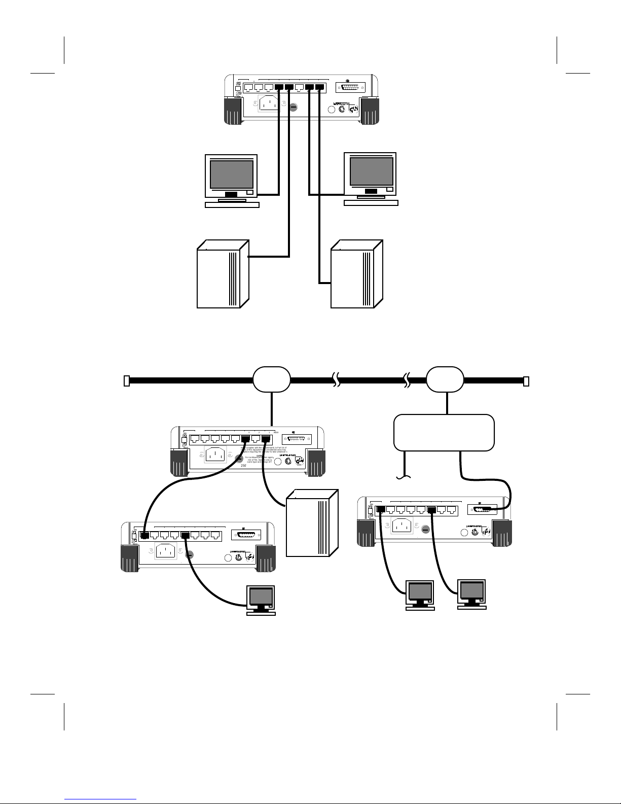
Figure 2 shows two sample network configurations using the LTR-T. Figure 2a shows a
simple network configuration using only 10BASE-T segments; Figure 2b shows a more
complex configuration using Thickwire Ethernet and interconnected LTR-T units. In
Figure 2b, the LTR-T on the left is directly connected from the AUI to the transceiver,
while the LTR-T on the right is connected from the AUI to a Local Network Interconnect
device.
You can connect one or more 10BASE-T segments to the LTR-T, one to each port on the
back of the unit. Additionally, you can connect multiple LTR-T units together, making
sure that there are no more than four LTR-T units between any two nodes. See the
Interconnection section below for important notes about interconnecting LTR-Ts. You
can also attach a transceiver to the AUI port to attach to 10BASE-T or Thinwire media.
If you need more information about rules you must follow when setting up your network,
refer to Appendix B.
LTR-T Installation Guide 5
Page 12
MDI
V
C
e
s
w
u
T
0
C
e
s
w
u
T
0
C
e
s
w
u
T
MDI-X
Serial #
LTR8T
95-250V~ 50-60Hz 0.5A T2A/250V
AUI 187654321
MDI-X
This equipment complies with the requirements in Part 15 of FCC Rules for a Class A Computing
device. Operation of this equipment in a residential area may cause unacceptable interference to radio
and TV reception requiring the operator to take whatever steps necessary to correct the interference.
CAUTION
For continued protection against
risk of fire, replace only with
same type and ratings of fuse
®
geprüfte
Sicherheit
MDI
MDI-X
Serial #
LTR
8
95-250V~ 50-60Hz 0.5AT2A/25
Workstation
THICKWIRE
ETHERNET
MDI
MDI-X
Serial #
LTR
8
95-250V~ 50-60Hz 0.5AT2A/250
This equipment complies with the requirements in Part 15 of FCC Rules for a Class A
device. Operation of this equipment in a residential area may cause unacceptable interfer
and TV reception requiring the operator to take whatever steps necessary to correct th
CAUTION
For continued protection again
risk of fire, replace only
same type and ratings of f
Workstation
HostHost
Figure 2a: A Simple Network Configuration
TRANSCEIVER TRANSCEIVER
AUI 187654321
MDI-X
This equipment complies with the requirements in Part 15 of FCC Rules for a Class A
device. Operation of this equipment in a residential area may cause unacceptable interfer
and TV reception requiring the operator to take whatever steps necessary to correct th
CAUTION
For continued protection again
risk of fire, replace only
same type and ratings of f
AUI 187654321
MDI-X
®
geprüfte
Sicherheit
®
geprüfte
Sicherheit
MDI
MDI-X
Serial #
LTR
8
95-250V~ 50-60Hz 0.5AT2A/25
host
LTX-5LTX-5
Local Network
Interconnect
AUI 187654321
MDI-X
This equipment complies with the requirements in Part 15 of FCC Rules for a Class A
device. Operation of this equipment in a residential area may cause unacceptable interfer
and TV reception requiring the operator to take whatever steps necessary to correct th
CAUTION
For continued protection again
risk of fire, replace only
same type and ratings of f
®
geprüfte
Sicherheit
6 LTR-T Installation Guide
Figure 2b: A Complex Network Configuration
Page 13
Cabling Instructions
A
0
s
t
s
s
1
X
X
t
RCOL
TACT
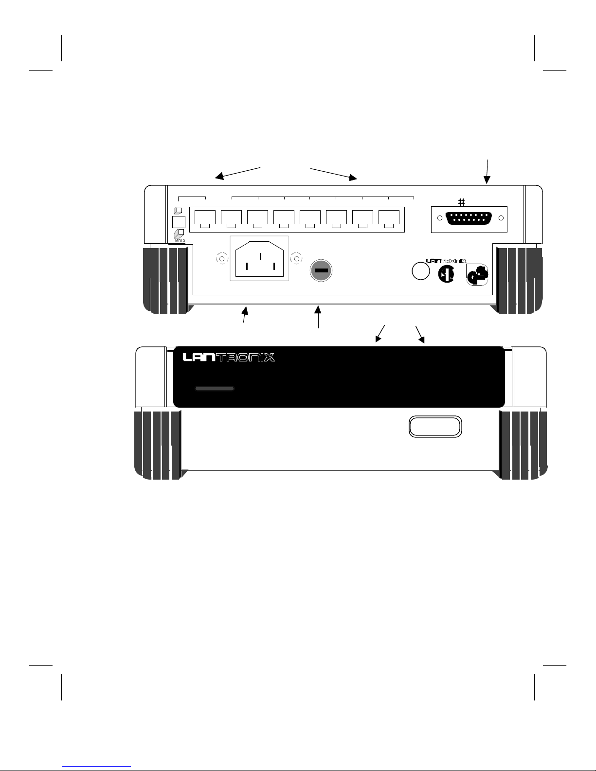
As you follow these instructions, refer to Figure 3 for an illustration of the LTR-T back
panel. Figure 3 shows the location of the 10BASE-T ports, AUI port, power cord, and
fuse.
MDI
MDI-
10BASE-T ports
87654321
This equipment complies with the requirements in Part 15 of FCC Rules for a Class A Computing
device. Operation of this equipment in a residential area may cause unacceptable interference to radio
and TV reception requiring the operator to take whatever steps necessary to correct the interference.
Serial
LTR
8T
95-250V~ 50-60Hz 0.5
AC input
---MODE---
PW
T2A/25
Fuse
STA
CAUTION
For continued protection again
risk of fire, replace only wi
same type and ratings of fu
Made in U.S.A.
Fabriqué aux Etats-Uni
AUI and 10BaseT Status
AUI 1 2 3 4 5 6 7 8
MDI-
U
®
L
UL 1950
Equipment
LISTED - 6J40
®
LR 89493
LTR8T
01
15 pin AUI por
AUI
geprüfte
Sicherheit
IEC 950
WARNING:
During the installation procedure some segments of your
network may be unstable. Individual packets on the attached
segments may be lost when new segments are added.
1. Label the 10BASE-T cables. Make sure each end of every cable is marked with
its LTR-T port number and destination. It is important that cable routing and all
connections to the UTP cables are documented. This information is valuable
during troubleshooting, maintenance, or reconfiguration of your network.
LTR-T Installation Guide 7
Figure 3: LTR-T Front and Back Panels
Page 14

2. Connect each 10BASE-T cable to the LTR-T. Make sure the port number on
0
s
t
e
n
u
the LTR-T matches the label on the cable, then insert one end of the cable into the
connector. Connect the other end of the cable to the workstation, host, or network
device. The AUI port and unused UTP ports can be left unconnected if not
needed.
3. AUI attachments: If you wish to use the AUI port as either a connection to a
backbone or as another 10BASE-T port, you will need to attach a transceiver to
the AUI port. Note that an AUI cable may be necessary between the LTR-T’s
AUI port and the transceiver itself. The AUI port can be connected to Thickwire,
Thinwire, or UTP by simply using an LTX-5, LTX-2 or LTX-T, respectively.
To connect the transceiver or AUI cable to the LTR-T, first unlock the slide latch
on the connector by sliding the clip to the right. You may have to slightly loosen
the screws on either side of the connector to move the latch. Next, connect the
transceiver or cable connector to the AUI port of the LTR-T (Figure 4). Finally,
lock the transceiver cable in place by sliding the latch to the left.
87654321
MDI
MDI-X
Serial #
LTR
8
95-250V~ 50-60Hz
T
This equipment complies with the requirements in Part 15 of FCC Rules for a Cla
device. Operation of this equipment in a residential area may cause unacceptable int
and TV reception requiring the operator to take whatever steps necessary to correc
0.5A
T2A/25
CAUTION
For continued protection agai
risk of fire, replace only wi
same type and ratings of f
MDI-X
AUI 1
®
geprˇÔte
Sicherheit
AUI
UNLOCK
Figure 4: Connecting the AUI cable to the AUI port
Figure 4: Connecting the Transceiver Cable to the AUI Port
8 LTR-T Installation Guide
Page 15

5. Connect the power cord to the LTR-T. The LTR-T can accept power from
either 110 Vac or 220 Vac outlets directly, therefore, there is no need to use a
voltage adapter.
Warning:
To reduce the risk of electric shock, in countries using an IT
power system or where protective earth ground connection is
not made, the ground conductor of the power cable should be
connected to earth ground.
6. Turn the repeater on. The LTR-T should automatically begin the self-test
procedure, described in the next section, to check the status of the hardware. If no
LEDs come on, refer to the “Testing and Diagnostics” section for troubleshooting
suggestions.
Adding New Network Segments
It is not necessary to remove power to the LTR-T when adding new segments to an
existing network. However, adding or removing an existing connection may disrupt the
transmission of an individual Ethernet packet. It is the intent of the IEEE Ethernet
specification that this be a recoverable error at the software level.
To add a new segment to the LTR-T, simply connect the new segment to the LTR-T port.
If there are no faults on the new segment, the LTR-T will automatically integrate the
segment into the existing network.
LTR-T Installation Guide 9
Page 16

Power-up Sequence
This section explains the LTR-T power-up diagnostics and interpretation of the LED
display during normal operation. At the end of this section you will find suggestions for
troubleshooting problems with the unit as well as maintenance information.
LED Test
Upon turning on the LTR-T you will observe the power-up LED test sequence. The
status (STAT) LEDs will display a sequence of green, yellow, and red LEDs while a
single green LED follows along in the activity (ACT) row(s) of LEDs. The collision
(COL) LED should be red during this pattern. If the LEDs do not behave in this manner
then please refer ahead to the section on Troubleshooting.
Firmware Version
After the testing the LEDs, the LTR-T will display the firmware version of your LTR-T
unit. This display will last approximately 3 seconds and is indicated by all green STAT
LEDs. The firmware version will be displayed by the ACT LEDs numbered one (1)
through eight (8) in a binary format. A lit LED corresponds to a one (1) in that bit
position while an unlit LED corresponds to a zero (0) in that bit position. For example,
version 1.3 will be displayed as
(0) (0) (0) (1) (0) (0) (1) (1)
off off off green off off green green
Diagnostics
After displaying the firmware version, the LTR-T will display the results of the power-up
diagnostics tests if any type of failure was detected. Otherwise, the LTR-T will proceed
directly to status mode.
Diagnostic display mode is indicated by either all yellow or all red STAT and power
(PWR) LEDs. The diagnostic code is displayed using the ACT LEDs in a similar manner
as described above in the section on Firmware Version. In addition, the COL LED
contains information that may be useful in diagnosing problems with your LTR-T. Please
refer to Table 3 for a description of the diagnostic codes.
1. The AUI-ACT LED should be off. The COL LED will be red if the unit is an
LTR-16T; the LED will be off if it is an LTR-8T. If the COL LED does not
reflect the true hardware type, it may indicate a hardware fault. Try cycling
power to the hub and see if the indication persists. If so, contact your dealer or
Lantronix.
2. The diagnostic results will be shown on the upper right 9 LEDs - Table 3 explains
the meaning of the LED colors.
10 LTR-T Installation Guide
Page 17

STAT LEDs Explanation
YELLOW LTR-T is powering-up to the factory default configuration.
This is expected if during power-up both front panel buttons
were pressed. Otherwise, this display indicates that the nonvolatile RAM (NVR) has failed and the unit should be returned
to Lantronix for servicing.
0000 0001 - NVR checksum error - power-up defaults used.
0000 0010 - User requested power-up defaults.
RED LTR-T failed power-up diagnostics. The ACT LEDs indicate
the diagnostic code in binary format:
0000 0001 - Upper board failure (LTR16T).
0000 0010 - NVR failure.
0000 0100 - Inter-board communication failure (LTR16T).
Having failed power-up diagnostics, the LTR-T will disable all
ports and continue to display the diagnostic code indefinitely.
Lantronix or your dealer should be contacted.
Table 3: Power-up Diagnostic Codes
Upon successfully completing the power-up diagnostics, the LTR-T will begin normal
operation in status mode as indicated by the following LED displays:
1. The power LED blinks green.
2. The status of the AUI and UTP ports is displayed by their corresponding STAT
LEDs (see Table 4, below, for a description of the port STAT LEDs.)
3. Port activity is indicated by the corresponding ACT LEDs.
4. Network collisions are indicated by the COL LED.
LTR-T Installation Guide 11
Page 18

Troubleshooting
If your LTR-T unit does not power-up properly, try the following:
1. Check the power cable. Verify that power is reaching the unit. The LTR-T can
receive power from either 110 Vac or 220 Vac outlets without any modification
to the hardware, however, you must make sure the unit is properly grounded.
2. Check that the LEDs light when the POWER switch is turned on. If they do
not light, check the fuse on the back of the unit to make sure that it is not blown.
3. Check that the LTR-T successfully completes the Power-Up diagnostics. The
Power-Up diagnostics are described earlier in this section. Refer to Table 3 for an
explanation of the LEDs displayed during the test.
If these suggestions do not help, please contact your dealer.
12 LTR-T Installation Guide
Page 19

Normal Operation
During normal operation the LTR-T displays the status and activity of all its attached
ports. The each port’s status is displayed as follows:
STAT LED Explanation
GREEN UTP ports
AUI ports
YELLOW UTP ports The LTR-T has detected reversed receive wires on this port and
RED UTP ports
AUI ports
The link is good and receive polarity is correct.
or
the link test function and/or polarity correction is disabled.
The attached transceiver is functioning normally
or
the AUI port does not have a transceiver attached.
is correcting the polarity before retransmitting the data. (Note:
if polarity correction is disabled, the LTR-T will neither check
nor correct the polarity of the data before retransmitting.)
The port is failing the link test if the test is enabled
and/or
the port has been automatically partitioned from the network
due to excessive collisions.
(Note: ports which have link test enabled, but are not connected
to a device at the opposite end of the segment will fail the link
test.)
The port has been automatically partitioned from the network
due to excessive collisions. In this state the port continues to
transmit, but receive data and collisions are ignored until the
LTR-T is able to determine that the segment is no longer bad.
Blinking UTP and
Off UTP and
LTR-T Installation Guide 13
(Note: if the AUI port is connected to a Thickwire/Thinwire
segment that is not terminated properly, the port will be
partitioned by the LTR-T.)
The port was auto-partitioned out (due to line errors) and
AUI ports
AUI ports
Table 4: Explanation of Port Status LEDs
subsequently reinstated and is operating normally. The blinking
can be stopped by pressing the left MODE button.
The port has been manually partitioned from the network by the
user and is not capable of transmitting or receiving data (see the
section on Configuration for more information.)
Page 20

Configuration
The LTR-T has several features, configurable via the front panel:
1. Link test - Enabled on all UTP ports by default, the link test function
continuously checks the ports to verify that a proper connection exists between
each port and the device at the opposite end of the UTP cable. In order for the
link test function to pass, the device at the opposite end of the UTP cable must
support link test functionality. For proper functioning of the network, the link test
function must be disabled on all ports connected to devices that do not support the
link test function.
2. Polarity correction - Enabled on all UTP ports by default, the polarity correction
feature allows the LTR-T to detect reversed receive wires on the UTP cable by
monitoring the polarity of the incoming data. The LTR-T then corrects the
polarity of the data prior to retransmitting it to the other ports. If polarity
correction is not enabled, the LTR-T will neither detect nor correct the polarity of
incoming packets prior to retransmitting them.
3. Manual partitioning - Disabled on all ports by default, manual partition allows
the user to prevent ports from transmitting data to or receiving data from the
attached segment (in effect disabling the port.)
(Note: the LTR-T will automatically partition from the network any port on
which it detects excessive collisions. This is different from disabling a port via
manual partitioning in that auto-partitioned ports are re-instated to the network as
soon as the LTR-T decides that the segment is no longer bad.)
4. Port reconnection - There are two methods by which the LTR-T may determine
when a port should be re-instated after being auto-partitioned. from the network.
By default, all ports are re-instated if the LTR-T is able to receive or transmit data
to an auto-partitioned port without detecting a collision. Optionally, the LTR-T
can be configured to an alternate, more stringent method, in which it reinstates
only those ports to which it is able to transmit data without detecting a collision.
In both cases, the data must be a minimum of 512 bits in length.
The following feature is not controlled via the front-panel buttons:
5. Hub-to-hub interconnection - In many cases it is necessary to interconnect
multiple LTR-Ts to provide more than 8 or 16 UTP connections to the network.
Ports 8 and 16 (LTR16T) are configurable to simplify the cabling effort when
interconnecting LTR-Ts (see the section below on Hub Interconnection.).
14 LTR-T Installation Guide
Page 21

Configuration Mode
While in configuration mode the LEDs take on different meanings. The color of the
PWR LED indicates which function is being enabled/disabled. The STAT LEDs indicate
whether or not the particular function is enabled on each port, while the ACT LEDs
indicate which ports are selected for modification. In configuration mode, the front panel
buttons perform the following functions:
Pressing and releasing both MODE buttons moves to the next function from the list
(1-4) above. Note that the “next function” after Port Reconnection (number 4) is
to return to status mode:
Link Test Polarity
Correction
Manual
Partition
Reconnection
Method
Status Mode (running normally)
For each function, the right MODE (B) button is used to select which ports will be
affected by this function. The first time a function is entered, all ports are
selected by default. Pressing B repeatedly selects each single port in turn. Once
port 8 (or 16 for the LTR16T) is reached, the next port will return to either the
AUI port or UTP port 1, depending on the function. The ACT LEDs show which
ports are selected.
For each function, the left MODE (E) button toggles the current function for the
selected ports. If, for example, port 4 is selected in Link Test mode, pressing leftMODE toggles Link Test on and off for port 4. The STAT LEDs show the state
of the current function for the selected port.
In status mode, pressing B does nothing.
In status mode, pressing E clears any “history” of partitioned ports. If a port is auto-
partitioned out and then partitioned back in, its LED will blink until cleared with
this button. This is to show that the LTR-T recognized a problem with the
segment and subsequently corrected it.
To enter configuration mode, press both MODE buttons simultaneously.
LTR-T Installation Guide 15
Page 22

Link test mode is the first mode entered, and is indicated by the solid green PWR
LED. In this mode the LTR-T can enable/disable the link test function on any
combination of the UTP ports. The STAT LED above the lit ACT LED indicates
whether or not the link test is enabled on the selected port. Pressing B repeatedly
moves the ACT LED to each of the ports allowing the function to be
enabled/disabled on each of the ports independently. To exit link test mode press
both MODE buttons simultaneously.
Polarity correction mode (indicated by the yellow PWR LED) is entered after link
test mode. In this mode the LTR-T can enable/disable polarity correction on any
of the UTP ports. In the case of polarity correction, a yellow STAT LED
indicates that the function is enabled on the selected port. To exit polarity
correction mode press both MODE buttons simultaneously.
Manual partition mode (indicated by the solid red PWR LED) is entered after
polarity correction mode. In this mode the LTR-T can enable/disable partitioning
of any of the ports (UTP and AUI). Note that this function can be performed on
both AUI and UTP ports. In the case of manual partition, the STAT LEDs
display RED for those ports which have been manually partitioned from the
network. To exit manual partition mode press both MODE buttons
simultaneously.
Reconnection algorithm mode (indicated by the blinking red PWR LED) is entered
after manual partition mode. In this mode the LTR-T can enable/disable the
alternate reconnection method for all the ports in several combinations. For this
mode the UTP ports are configured together in groups of eight ports each and the
AUI port(s) are configured independently. UTP ports 1 to 8 are configured as one
group and UTP ports 9 through 16 (LTR16T) are configured as a second group.
The method for enabling/disabling the alternate reconnection method is similar to
that used in the above section on link test mode.
To return to normal operation in status mode press both MODE buttons simultaneously
from reconnection mode. If you save the configuration you set up (see next section) you
will also be returned to status mode.
Note that the LTR-T performs the actual modifications to the configuration upon
returning to status mode. Therefore, the LTR-T continues to perform its repeater
functions unchanged while in configuration mode.
16 LTR-T Installation Guide
Page 23

Storing Configuration
To store the current configuration of the LTR-T as the power-up default, press both
MODE buttons simultaneously and hold them for approximately 3 seconds. The store
operation can be performed while the LTR-T is in either status or configuration mode. If
a store is performed while in configuration mode, the LTR-T automatically exits
configuration mode and returns to status mode upon completing the operation. In the
event of a power failure, the LTR-T will be restored to the most recently saved
configuration on power-up. If no configuration has been stored the LTR-T will power-up
to the factory default configuration described below.
Factory Defaults
The LTR-T can be restored to the factory default configuration by pressing both MODE
buttons while powering-up the unit. The default configuration is as follows:
UTP Ports: Link test and polarity correction enabled. Manual partition and alternate
reconnection disabled.
AUI Port: Manual partition and alternate reconnection disabled.
LTR-T Installation Guide 17
Page 24

10BASE-T Wiring Conventions
There are two standard RJ45 pin assignments used in connecting 10BASE-T equipment
using unshielded twisted-pair (UTP) cable. They are referred to as an MDI (MediumDependent Interface) and MDI-X. The MDI designation refers to devices which transmit
on RJ45 pins 1 and 2 and receive on pins 3 and 6. MDI-X refers to devices which
transmit on pins 3 and 6 and receive on pins 1 and 2. In general, end nodes (Ethernet
cards, workstations, transceivers, etc.) are MDI, while virtually all 10BASE-T hubs and
concentrators are MDI-X. See Appendix B for the pinouts for the two cases.
The motivation behind using two different interface types is to simplify the wiring
between devices. For proper operation, the transmit signal pair at one interface must
connect to the receive signal pair at the second interface, and vice versa. Since MDI
devices are usually connected to MDI-X devices, a straight-through cable works in most
cases. A swapped cable exchanges the transmit signal pair with the receive signal pair in
the absence of an MDI-X device at one end of the cable. MDI-X can be thought of as
swapping the signals internally.
To connect two MDI devices (i.e., two workstations back to back), or two MDI-X devices
(i.e., two hubs) a swapped cable is required. Because connecting two hubs is a common
occurrence, however, the LTR-T provides one or two (LTR-16T ) ports that can be
switched between MDI and MDI-X, as discussed in the next section.
18 LTR-T Installation Guide
Page 25
Hub Interconnection
5
V
A
h
e
n
w
u
T
V
A
h
e
n
w
u
T
Ports 8 and 16 (LTR16T) are special in that they can be configured to simplify
interconnection of multiple LTR-Ts. To connect one LTR-T to another LTR-T the
MDI/MDI-X switch on the back of the unit can be used. See "10BASE-T Wiring
Conventions," above, for an explanation of the difference between connector wiring of
hubs and transceivers. Refer to the UTP pinout in Appendix B as you read this.
Each 10BASE-T port on the LTR-T hub is expecting a node at the remote end of the
segment. In anticipation of this, the transmit and receive signal pairs are crossed within
the hub, so that the hub's transmit signal pair becomes the node's receive signal pair and
vice versa. This works fine for hub-to-node connections. If two hubs are interconnected,
however, the signals will be swapped twice, once at each hub's MDI-X interface. One
solution is to use a swapped cable between the two hubs to introduce a third swapping of
the signal pairs. An easier solution is to use port 8 or port 16 (LTR16T) set to MDI on
one hub and connect to any MDI-X port on the second hub. This method requires the
same straight-through type of cable used for hub-to-node connections. (Note: The
interconnection will NOT work if the hubs are connected as MDI-X to MDI-X and a
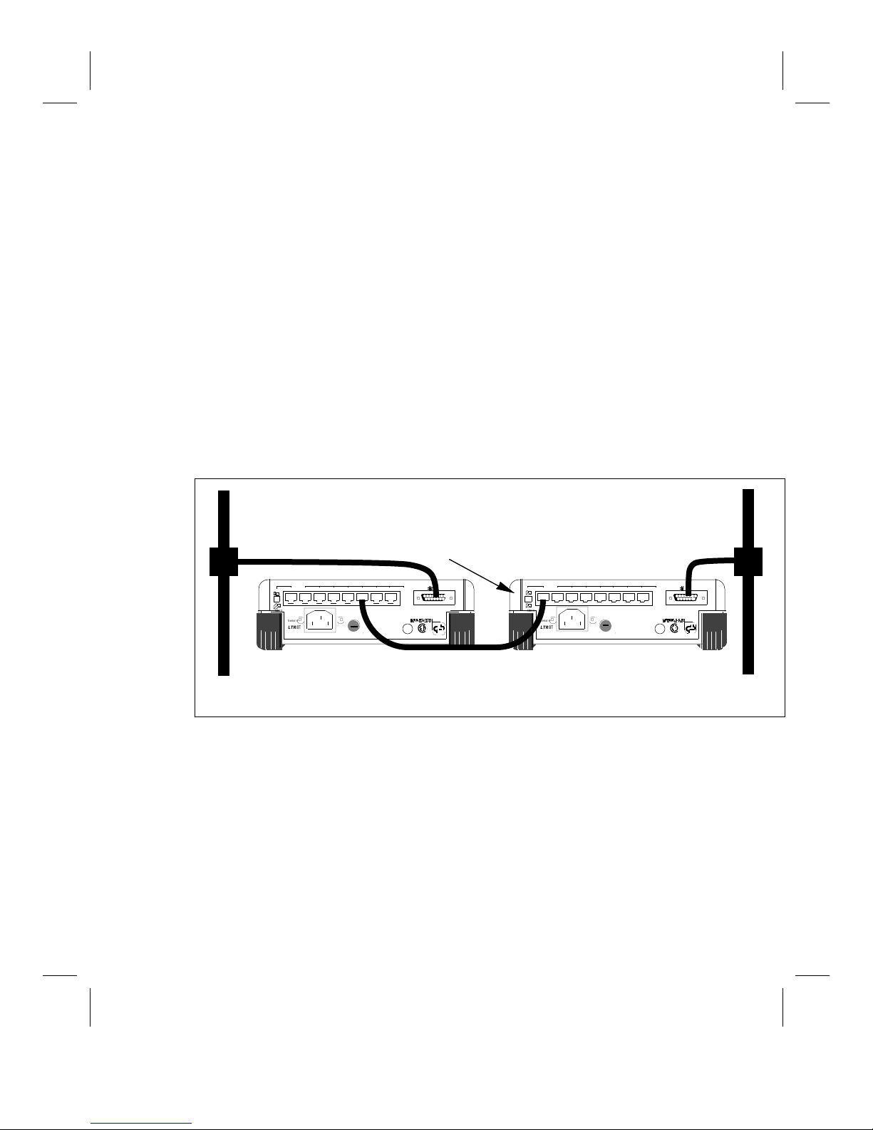
straight-through cable is used.) See Figures 2b and 5 for example networks.
Ethernet
Backbone
Note that Port 8 MUST
be in "MDI" mode for
Ethernet
Backbone
interconnecting to work.
AUI
87654321
MDI
MDI-X
Serial #
LTR
8
95-250V~ 50-60Hz 0.
This equipment complies with the requirements in Part 15 of FCC Rules for a Class
device. Operation of this equipment in a residential area may cause unacceptable interf
and TV reception requiring the operator to take whatever steps necessary to correct t
T2A/250
CAUTION
For continued protection agai
risk of fire, replace only
same type and ratings of f
AUI 1
MDI-X
®
geprüfte
Sicherheit
LTR-T
Figure 5: Example of Interconnecting Two LTR-Ts
87654321
MDI
MDI-X
Serial #
LTR
8
95-250V~ 50-60Hz 0.5T2A/250
This equipment complies with the requirements in Part 15 of FCC Rules for a Class
device. Operation of this equipment in a residential area may cause unacceptable interf
and TV reception requiring the operator to take whatever steps necessary to correct t
CAUTION
For continued protection agai
risk of fire, replace only
same type and ratings of f
MDI-X
AUI 1
®
geprüfteSicherheit
LTR-T
Maintenance Information
You do not need to perform any maintenance procedures on your LTR-T. The fuse is the
only user serviceable part, and under normal operating conditions it should not need to be
replaced.
AUI
LTR-T Installation Guide 19
Page 26

Glossary
Attachment Unit Interface (AUI) Cable
A 15-pin shielded, twisted pair cable used (optionally) to connect the LTR-T to a
transceiver or LNI-type device.
Branch
See Segment.
Hub
See Repeater.
Local Network Interconnect
A device that allows two or more devices access to the network medium via a single
transceiver.
Medium Attachment Unit (MAU)
See Transceiver.
Network
A set of computer devices that are connected together so they can communicate with each
other. A typical network consists of computers, terminals, and printers.
Node
Any device on the network capable of generating and receiving Ethernet traffic. This can
be a workstation, terminal server, printer, etc. In general, any device with its own
ethernet address is a node. Repeaters and LNIs are not nodes, as they only regenerate
traffic that is already on the network.
Port Partitioning
The ability to temporarily disable one segment of a network while continuing
communication on the other segments. The LTR-T allows the user to manually partition
each of its ports in addition to its auto-partitioning feature, which partitions ports that
experience excessive collisions.
Repeater
A device used to extend the length, topology, or connectivity of the physical medium
beyond that imposed by a single segment, up to the maximum allowable end-to-end
transmission line length. Repeaters restore the signal amplitude, waveform, and timing of
20 LTR-T Installation Guide
Page 27

normal data and collision signals. The LTR-T is an example of a repeater, and the
physical medium that it uses is unshielded twisted-pair (UTP).
Segment
A length of coaxial or UTP cable. The LTR-T passes signals from each of its segments to
all other attached segments. A segment must be terminated at both ends, either via
terminators (10BASE2, 10BASE5) or devices (10BASE-T).
Tap
A tap usually refers to a physical connection to the network where other devices can be
attached. Taps may be of several types, including BNC taps, simple “T” taps, or
Thickwire Vampire taps that attach directly to a network cable and “inject” signals into
the cable.
Thickwire (10BASE5) Ethernet
This is also known as standard Ethernet. It specifies the physical layer according to IEEE
802.3, 10BASE5. It is thick coaxial cable, specified as 50 ohm RG10 cable. Thickwire
Ethernet has stricter rules for network configurations to allow the maximum transmission
distance of 500 meters.
Thinwire (10BASE2) Ethernet
An alternative physical layer for Ethernet specified as IEEE 802.3, 10BASE2. It is a
more flexible cable than Thickwire Ethernet with less stringent rules for attaching to the
cable. Maximum segment length is 185 meters. It is specified as 50 ohm RG58 cable
and is often referred to as “Cheapernet.”
Transceiver
In general, a device used to connect a network node/device to the Ethernet media. It
passes signals between the Ethernet and the AUI port, performing necessary interface
functions. For example, the LTX-2 attaches to Thinwire media, the LTX-5 attaches to
Thickwire , and the LTX-T attaches to unshielded twisted pair (UTP) cable.
Transceiver Cable
See Attachment Unit Interface (AUI) cable.
Unshielded Twisted Pair (UTP)
The physical layer medium referred to by the IEEE 802.3 10BASE-T specification.
Unshielded twisted pair cable consists of wires that are twisted together in pairs and
enclosed within a single jacket. In general, existing telephone cable can be used if it is of
high enough quality to support high-speed communications. Common UTP cable
provides 4 pairs of wires, thus can support two 10BASE-T connections. Each segment
can be a maximum of 100 meters long.
LTR-T Installation Guide 21
Page 28

Page 29

Appendix A: Power Supply Cord
Cord type: 3 conductors
1.0 mm2 minimum conductor size (approx. 18 AWG)
Rated for 250 Volts AC, 10 Amps
Length ≤ 3.0 meters (10 feet)
The cord should have a harmonized cable type number. (“Harmonized” refers to an
internationally standardized cable description, and is prefixed by the letters HAR.) An
example of a valid harmonized cord type is:
HAR HO5VV-F 3G1.00
Connectors: The cord should terminate in a molded-on IEC 320-C13 female connector
body at one end for proper interface to the LTR-T. The other end should be of a plug
configuration appropriate to the country in question.
Grounding Warning: To reduce the risk of electric shock, in countries using an IT
power system or where protective earth ground connection is not made, the ground
conductor of the power cable should be connected to earth ground.
Approvals: The cord connectors should bear the approval mark of at least one of the
following regulatory and safety agencies:
CEBEC
Belgium (CEBEC)
V
DE
Germany (VDE)
Sweden (SEMKO)
Italy (IMQ)
FI
Finland (EI)
EMA
EUR
K
Netherlands (KEMA)
United Kingdom (BSI)
(Note: The above symbols are approximate representations of the actual
approval symbols, and are for the user's reference only.)
OVE
Austria (OVE)
N
Norway (NEMKO)
ASSESSED
QUALITY
ASA
T
BS 5750
United Kingdom (ASTA)
D
Denmark (DEMKO)
+
S
Switzerland (SEV)
F
N
France (UTE)
LTR-T Installation Guide Appendix A-23
Page 30

Page 31

Appendix B: Cabling
This appendix explains the different types of cable available to meet your networking
needs -Thickwire, Thinwire, and unshielded twisted pair (UTP). Refer to the Glossary
for an explanation of these and other terms used in this section.
The LTR-T interfaces directly to UTP Ethernet. Ethernet over UTP is functionally the
same as Thickwire or Thinwire Ethernet. An advantage of UTP cabling is the fact that
there is an installed base of UTP in many buildings for the purpose of telephone
communications. This installed base can often be used as the networking medium, thus
reducing the need to run Thickwire or Thinwire throughout the entire building. The
addition of UTP cable to an existing network allows more flexibility in setting up work
groups.
If you are starting your network from scratch, the LTR-T can be used to connect 8 or 16
(LTR16T) devices in a “star” topology using only UTP cable, without the addition of
external transceivers at the repeater end. With the addition of one or two (LTR16T)
external LTX-Ts (or equivalent 10BASE-T transceivers) up to two additional UTP ports
are available. The “star” topology contrasts with Thinwire and Thickwire Ethernet,
which connect each node to a coaxial cable in a “bus” topology. UTP is ideal for small
office environments because the cable is less expensive and easier to install than Ethernet
coaxial cable. The connection from the user’s system to the network is made via a single
UTP cable, therefore, no complex cable handling is required. Many configurations are
possible. Several UTP segments can be connected together through one or more hubs.
Hubs can also be connected using a Local Network Interconnect to one (or possibly
more) Thickwire/Thinwire Ethernet cables.
There are three rules that must be followed to ensure reliable communication:
A single segment of UTP cable can be no more than 100 meters in length.
You cannot connect 2 ports on the same LTR-T together (via one UTP cable or
otherwise).
You cannot create a network loop. For example, you cannot interconnect 2 LTR-Ts
with 2 segments.
The same LTR-T can be used to connect to a Thickwire/Thinwire Ethernet. The LTR-T
provides one or two (LTR16T) AUI ports for connecting a transceiver or AUI cable to the
unit. The AUI cable connects the transceiver to the LTR-T in cases where the transceiver
is in a remote location or is too large to connect directly to the LTR-T.
Thinwire cable is specified as RG58, which is a 50 ohm cable. Thickwire cable is
specified as RG10, and is also 50 ohms.
LTR-T Installation Guide Appendix B-25
Page 32
For most environments, it is acceptable to use standard 24 AWG unshielded twisted pair
(UTP) telephone wire as your network medium. However, if the network is to be
installed in a “noisy” environment (a location with high electromagnetic interference) it
may be necessary to use a data-grade UTP cable instead. In extreme cases, it may be
necessary to install shielded twisted pair (STP) cable for specific network segments,
however, the use of STP cable is beyond the scope of this manual.
In general, phone signals and 10BASE-T signals can be carried by different pairs of the
same length of UTP cable. Verify this with your local telephone installer or network
managers before using your cabling in this way
For additional networking information, please consult your equipment dealer.
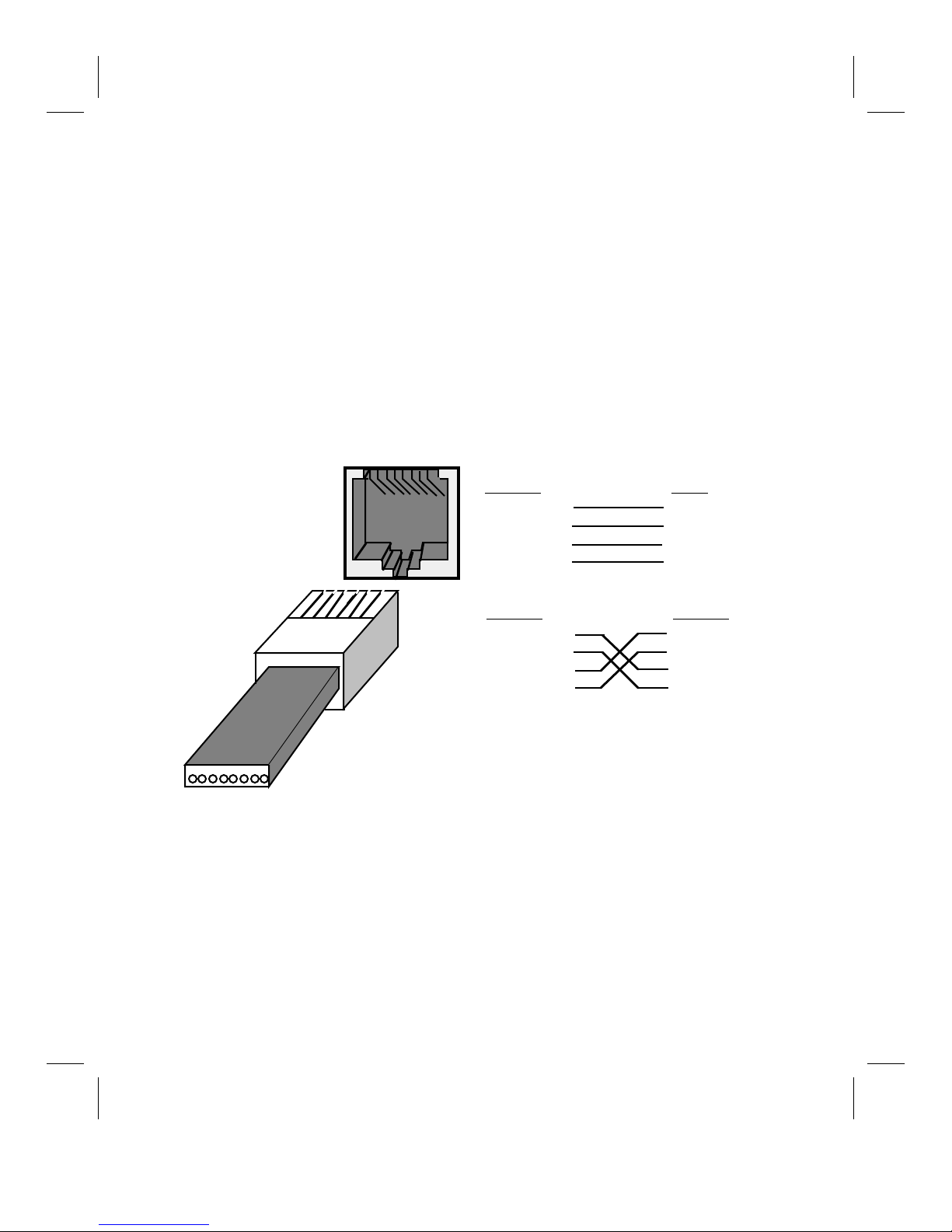
RJ45 Pinout
RJ45 Port
12345678
12345678
RJ45
Connector
Straight-through cable
MDI-X
Pin 1: Rx+
Pin 2: RxPin 3: Tx+
Pin 6: Tx-
MDI
Pin 1: Tx+
Pin 2: TxPin 3: Rx+
Pin 6: Rx-
Swapped (crossed) cable
MDI-X
Pin 1: Rx+
Pin 2: RxPin 3: Tx+
Pin 6: Tx-
MDI-X
Pin 1: Rx+
Pin 2: RxPin 3: Tx+
Pin 6: Tx-
Ports 1-7 and 9-15 always use straightthrough cables to connect to transceivers.
Ports 8 & 16 use straight-through cables to
connect to transceivers when in MDI-X mode
and to other hubs when in MDI mode.
Appendix B-26 LTR-T Installation Guide
Page 33

Lantronix Problem Report Procedure
If you are experiencing problems with your Lantronix product, please contact Lantronix'
Technical Service department.
LANTRONIX
15353 Barranca Parkway
Irvine, California 92718
714-453-3990 • FAX 714-453-3995
Direct Sales 1-800-422-7055 • Technical Support 1-800-422-7044
Internet email address: support@lantronix.com
To assist in diagnosing the problem, please have the following information available
when you call:
Your name and your company’s name, address, and phone number:
Product name:
Lantronix serial number :
Prom version:
Network configuration:
Description of the problem:
Product status when the problem occurred (what was the last activity the product did?):
LTR-T Installation Guide Appendix B-27
Page 34

Appendix B-28 LTR-T Installation Guide
Page 35

Warranty
Lantronix warrants for a period of FIVE YEARS from the date of shipment that each Lantronix LTR8T or
LTR16T supplied shall be free from defects in material and workmanship.
During this period, if the customer experiences difficulties with a product and is unable to resolve the problem
through correspondence with Lantronix Technical Support, a Return Material Authorization (RMA) will be
issued. Following receipt of an RMA number, the customer is responsible for returning the product to
Lantronix, freight prepaid. Lantronix, upon verification of warranty will, at its option, repair or replace the
product in question, and return it to the customer freight prepaid.
If the product is not under warranty, Lantronix will contact the customer who then has the option of having the
unit repaired on a fee basis or having the unit returned.
No services are handled at the customer’s site under this warranty.
Lantronix warrants software for a period of sixty (60) days from the date of shipment that each software
package supplied shall be free from defects and shall operate according to Lantronix specifications. Any
software revisions required hereunder cover supply of distribution media only and do not cover, or include, any
installation. The customer is responsible for return of media to Lantronix and Lantronix for freight associated
with replacement media being returned to the customer.
Lantronix shall have no obligation to make repairs or to cause replacement required through normal wear and
tear of necessitated in whole or in part by catastrophe, fault or negligence of the user, improper or unauthorized
use of the Product, or use of the Product in such a manner for which it was not designed, or by causes external
to the Product, such as, but not limited to, failure of power or air conditioning.
There are no understandings, agreements, representations or warranties, express or implied, including
warranties of merchantability or fitness for a particular purpose, other than those specifically set out above or by
any existing contract between the parties. Any such contract states the entire obligation of Lantronix. The
contents of this document shall not become part of, or modify, any prior or existing agreement, commitment or
relationship.
The information, recommendation, description and safety notations in this or other documents supplied by
Lantronix are based on general industry experience and judgement with respect to such hardware and software.
THIS INFORMATION SHOULD NOT BE CONSIDERED TO BE ALL INCLUSIVE OR COVERING ALL
CONTINGENCIES.
NO OTHER WARRANTIES, EXPRESS OR IMPLIED, INCLUDING WARRANTIES OF FITNESS FOR A
PARTICULAR PURPOSE OR MERCHANTABILITY, OR WARRANTIES ARISING FROM COURSE OF
DEALING OR USAGE OF TRADE, ARE MADE REGARDING THE INFORMATION,
RECOMMENDATIONS, DESCRIPTIONS AND SAFETY NOTATIONS CONTAINED HEREIN AND IN
HARDWARE AND SOFTWARE SPECIFICATION DOCUMENTATION, OR INSTRUCTIONS SUPPLIED
BY LANTRONIX. In no event will Lantronix be responsible to the user in contract, in tort (including
negligence), strict liability or otherwise for any special, indirect, incidental or consequential damage or loss of
equipment, plant or power system, cost of capital, loss of profits or revenues, cost of replacement power,
additional expenses in the use of existing software, hardware, equipment or facilities, or claims against the user
by its employees or customers resulting from the use of the information, recommendations, descriptions and
safety notations supplied by Lantronix. Lantronix’ liability is limited (at its election) to (1) refund of buyer’s
purchase price for such affected products (without interest); (2) repair of such products, or (3) replacement of
such products, provided however, that the buyer follows the procedures set forth herein.
Warranty claims must be received by Lantronix within the applicable warranty period. A replaced product, or
part thereof, shall become the property of Lantronix and shall be returned to Lantronix at the Purchaser’s
expense. ALL RETURN MATERIAL MUST BE ACCOMPANIED BY A RETURN MATERIAL
AUTHORIZATION NUMBER ASSIGNED BY LANTRONIX.
LTR-T Installation Guide Warranty-29
Page 36

Declaration of Conformity
(accordingly to ISO/IEC Guide 22 and EN 45014)
Manufacturer’s Name: Lantronix
Manufacturer’s Address: 15353 Barranca Parkway
Irvine, CA 92718 USA
declares, that the product:
Product Name: Ethernet Repeater
Model Number(s): LTR8T and LTR16T
conforms to the following Standards:
Safety: EN 60950:1988 + A1, A2
EMC: EN 50022:1988 class A
EN 55082-1:1992
IEC 801-2:1991/prEN55024-2:1992-4kVCD, 8kVAD
IEC 801-3:1992/prEN55024-3:1991-3V/m
IEC 801-4:1988/prEN55024-4:1992-0.5kV Signal Lines,
1kV Power Lines
Supplementary Information:
“The product complies with the requirements of the Low Voltage Directive
73/23/EEC and the EMC Directive 89/336/EEC.”
Manufacturer’s Contact:
Director of Quality Assurance
Lantronix
15353 Barranca Parkway
Irvine, CA 92718 USA
Direct Tel: 714/453-7165; Fax: 714/450-7237
General Tel: 714/453-3990; Fax: 714/453-3995
 Loading...