

Page 1
LPSW2400S_UG_ENB01W
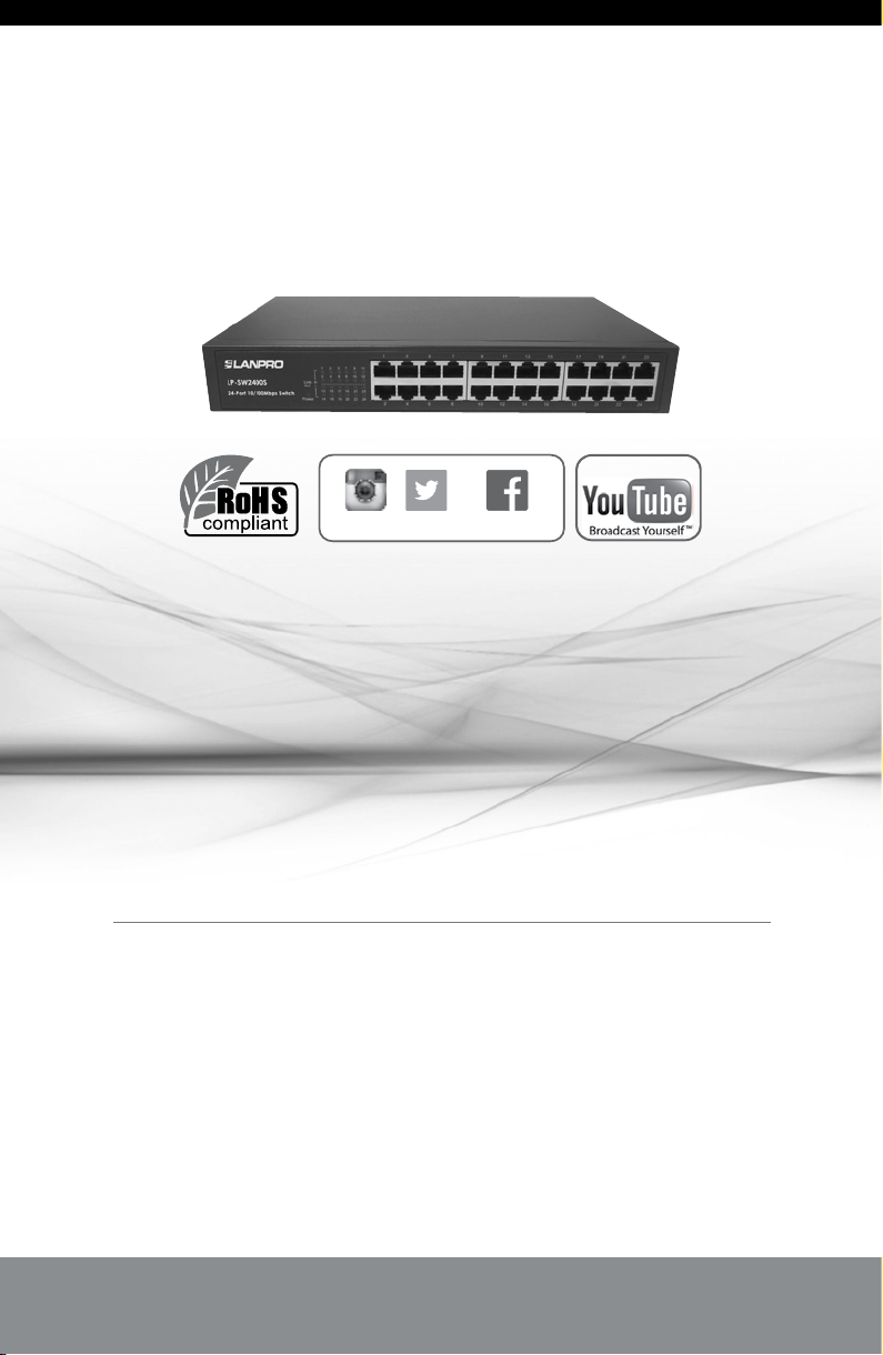
SW2400S
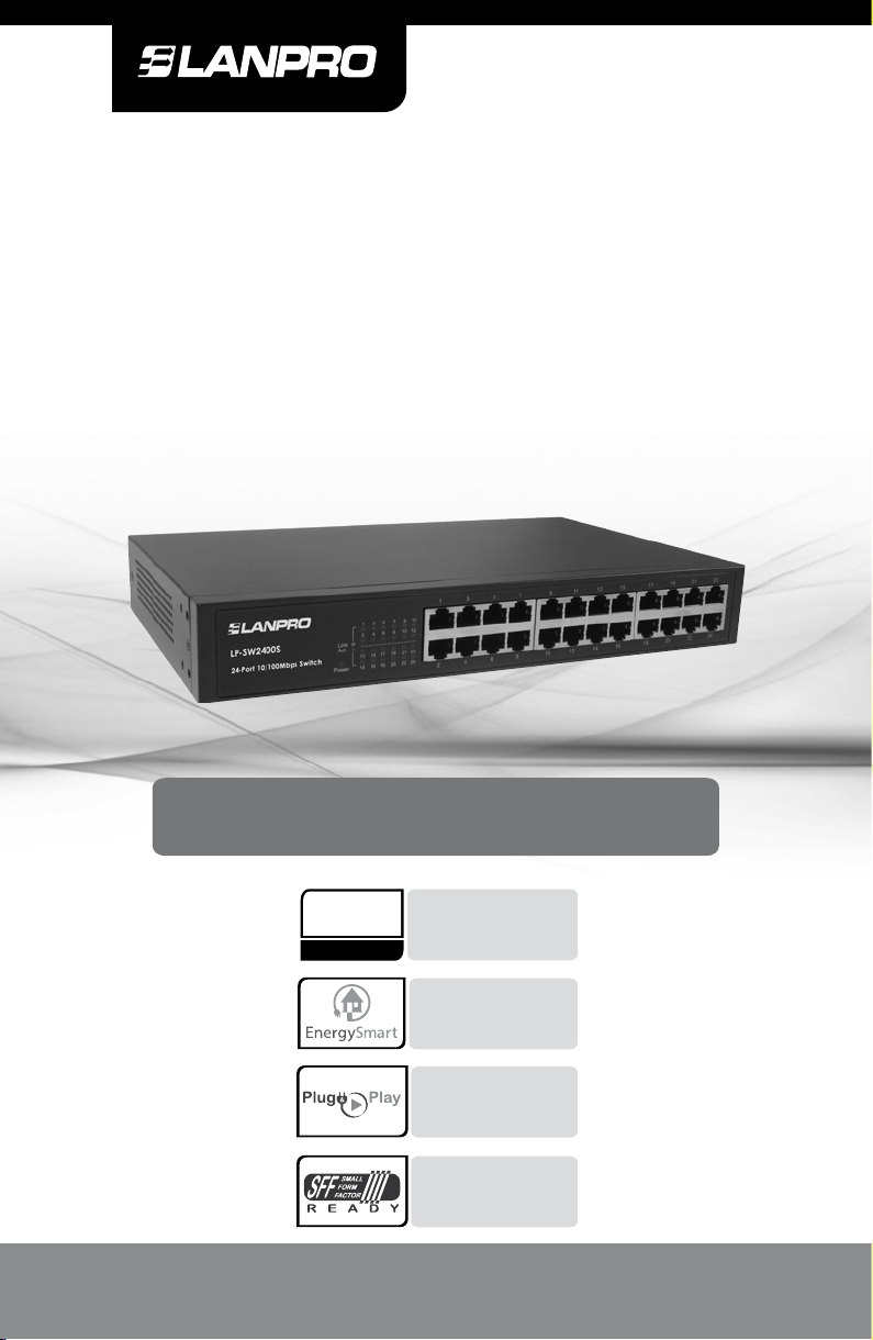
24-Port SFF 10/100Mbps
Fast Ethernet Switch
Model: LP-SW2400S
User Guide
Up to 200Mbps full duplex
200
Mbps
www.lanpro.com
bandwidth capability
for high speed data
processing
Innovative Energy-Smart
technology saves power
up to 70%
Hassle free setup,
no configuration
required
Small Form Factor,
can be installed on a
shelf or rack mount.
Page 2

LP-SW2400S ▪ 24-port 10/100Mbps Fast Ethernet Switch ▪ User Guide ▪ www.lanpro.com
COPYRIGHT & TRADEMARKS
Specications are subject to change without notice. LanPro is a
registered trademark of LanPro Inc. Other brands and product names
are trademarks or registered trademarks of their respective holders.
No part of the specications may be reproduced in any form or by
any means or used to make any derivative such as translation,
transformation, or adaptation without permission from LanPro Inc.
Copyright © 2015 LanPro Inc. All rights reserved.
www.lanpro.com
Mark Warning
This is a class A product. In a domestic environment, this product may
cause radio interference, in which case the user may be required to
take adequate measures.
2
Page 3

LP-SW2400S ▪ 24-port 10/100Mbps Fast Ethernet Switch ▪ User Guide ▪ www.lanpro.com
CONTENTS
Package Contents ...................................................................... 4
Chapter 1 Product Introduction...................................... 5
1.1 Product Overview ............................................ 5
1.2 Features .......................................................... 5
1.3 IEEE 802.1p QoS ............................................ 6
1.4 Priority levels Table .......................................... 7
Chapter 2 Identifying External Components ................ 7
2.1 Front Panel ...................................................... 7
2.2 Rear Panel ...................................................... 8
Chapter 3 Installation ..................................................... 8
3.1 Precautions ..................................................... 8
3.2 Installation ....................................................... 9
3.2.1 Desktop Installation ............................... 9
3.2.2 Rack Installation .................................... 10
3.3 Connect to Ground .......................................... 12
3.4 Power on ......................................................... 13
Appendix A: Specications ................................................ 14
Appendix B: Troubleshooting ............................................ 15
3
Page 4
LP-SW2400S ▪ 24-port 10/100Mbps Fast Ethernet Switch ▪ User Guide ▪ www.lanpro.com
Package Contents
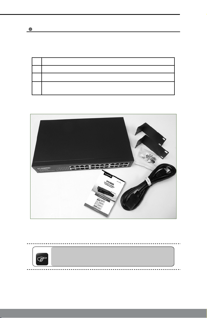
The following contents should be found in your box:
a.- One LP-SW2400S switch .
b.- One power cord .
c.- Installation Guide.
1 Set of screws for attaching two “L” brackets used for
d.-
mounting on 19 inch racks.
Figure 1. Package Contents
Note:
Make sure that the package contains the above items. If any
of the listed items are damaged or missing, please contact
with your distributor.
4
Page 5
LP-SW2400S ▪ 24-port 10/100Mbps Fast Ethernet Switch ▪ User Guide ▪ www.lanpro.com
Chapter 1: Product Introduction
This chapter describes the features of the model of LP-SW2400S 24-port
10/100Mbps Fast Ethernet Switch.
Product Overview
1.1
LP-SW2400S 24-port switch provides 24 10/100Mbps Auto-Negotiation
RJ45 ports. Each port of the LP-SW2400S supports auto MDI/MDI-X
function, eliminating the need for crossover cables or Uplink ports. The
switch is Plug-and-Play and any port can be simply plugged into a server, a
hub or a switch by using straight cable or crossover cable.
The LP-SW2400S 24-port 10/100Mbps Fast Ethernet Switch provides you
with a low-cost, easy-to-use, high-performance, seamless and standard
upgrade to improve your old network to a 100Mbps network. It will boost
your network performance up to full duplex data transfer.
The LP-SW2400S switch supports Energy-Smart technology, with power
saving features to help make your network environmentally friendly without
compromising performance. The switch automatically powers down ports
that have no link and budgets power output for different Ethernet cable
lengths. It can also reduce the power consumption in idle mode or with low
trafc mode.
Features
1.2
Complies with IEEE802.3, IEEE802.3u, IEEE802.3az, IEEE
►
802.1p standards.
24 10/100Mbps Auto-Negotiation RJ45 ports supporting Auto-
►
MDI/MDIX.
Supports IEEE802.3X ow control for full-duplex mode and
►
backpressure for half-duplex mode.
►
Supports IEEE 802.1p QoS.
►
Supports power saving features, with Energy-Smart Technology.
►
LED indicators for monitoring power, link and activity.
Desktop or 19 Inch Rack mountable 11.6 Inch wide Small Form
►
Factor (SFF) Steel case.
►
Internal power supply.
►
Plug and Play
5
Page 6
LP-SW2400S ▪ 24-port 10/100Mbps Fast Ethernet Switch ▪ User Guide ▪ www.lanpro.com
IEEE 802.1p QoS
1.3
The LP-SW2400S switch supports 802.1p priority queuing Quality of
Service (QoS), which is an implementation of the IEEE 802.1p standard.
With 802.1p QoS function, you can reserve bandwidth for important
functions that require a large bandwidth or have a high priority, such as
VoIP (Voice-over Internet Protocol), web browsing applications or video
conferencing. The switch has separate hardware queues on every physical
port which packets from various applications are mapped to and assigned
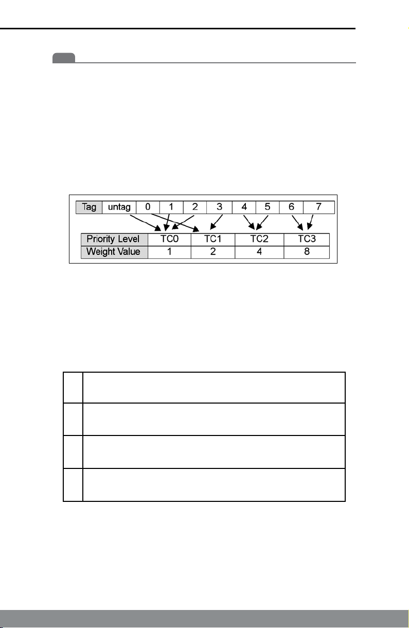
a priority to. The illustration below shows how 802.1p priority queuing is
implemented on the switch.
Figure 2. Mapping QoS on the Switch
The switch has four priority levels labeled TC0, TC1, TC2 and TC3. The
untagged packets and the eight IEEE 802.1p priority tags dened by the
standard are mapped to the four level queues used on the switch. TC3
has the highest priority of the four priority level queues while TC0 has the
lowest priority on the switch. The untagged packets and eight priority tags,
specied in IEEE 802.1p are mapped to the switch’s priority tags as follows:
The untagged packets, packets with priority tag 1 and 2 are
►
assigned to the switch’s TC0 level queue.
Packets with priority tag 0 and 3 are assigned to the switch’s
►
TC1 level queue.
Packets with priority tag 4 and 5 are assigned to the switch’s
►
TC2 level queue.
Packets with priority tag 6 and 7 are assigned to the switch’s
►
TC3 level queue.
The switch uses WRR (Weighted Robin Round) for scheduling. WRR
queue-scheduling algorithm schedules all the queues in turn and every
queue can be assured of a certain service time. The default weight value of
TC0, TC1, TC2 and TC3 is 1:2:4:8.
6
Page 7
LP-SW2400S ▪ 24-port 10/100Mbps Fast Ethernet Switch ▪ User Guide ▪ www.lanpro.com
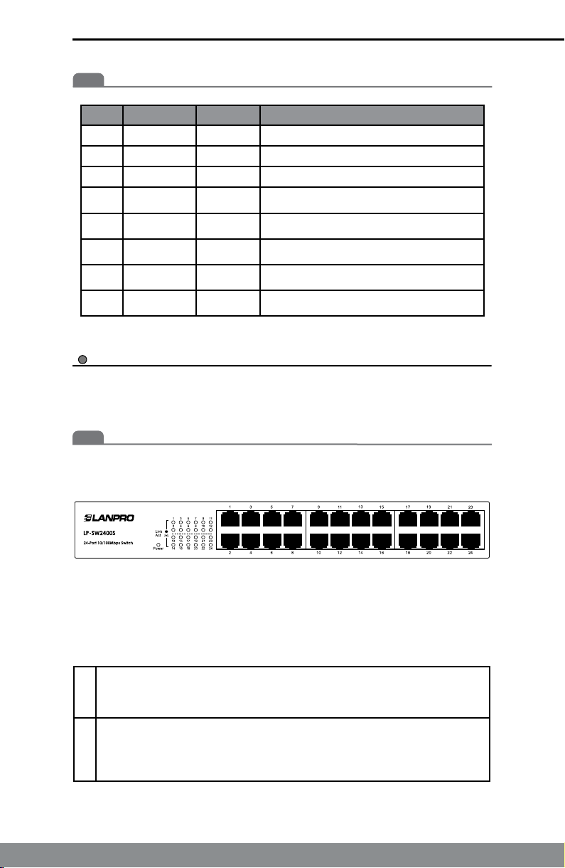
Priority Levels Table
1.4
PCP Priority Acronym Trafc Types
1 0 (Lowest) BK Background
0 1 BE Best Effort
2 2 EE Excellent Effort
3 3 CA Critical Applications
4 4 VI Video, < 100 ms latency and jitter
5 5 VO Voice, <10ms Latency and Jitter
6 6 IC Internetwork Control
7 7 (Highest) NC Network Control
Chapter 2: Identifying External Components
This chapter describes the front panel, rear panel and LED indicators of
the switch.
Front Panel
2.1
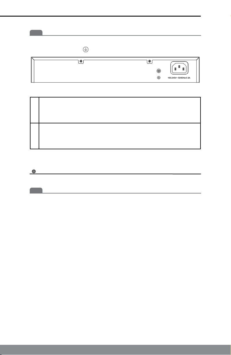
The front panel of LP-SW2400S consists of switch model, switch LED
indicators, and 24 10/100Mbps RJ-45 ports.
Figure 3. Switch Front Panel Sketch
The LED indicators include Power, Link/Act LED indicators, which are used
for monitoring and pre-troubleshooting of the switch. The following section
shows the LED indicators of the switch along with explanation of each
indicator.
►
Power LED: This indicator will light solid green when the switch
powers up. If the LED is not lit, please check the power supply and
connection.
►
Link/Act LED: The LED indicates Link/Active status. The
corresponding LED indicator will light solid green when connected to
a network device. It ashes green when data is being transmitted or
received on the working connection.
7
Page 8
LP-SW2400S ▪ 24-port 10/100Mbps Fast Ethernet Switch ▪ User Guide ▪ www.lanpro.com
Rear Panel
2.2
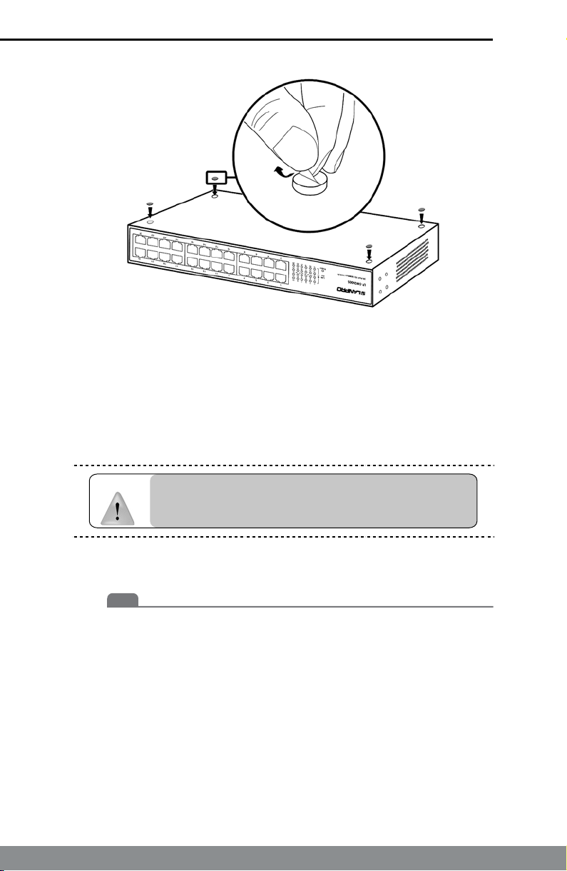
The rear panel of LP-SW2400S features a power socket and a Grounding
Terminal (marked with ).
Figure 4. Switch Rear Panel Sketch
►
Grounding Terminal: LP-SW2400S already comes with Lightning
Protection Mechanism. You can also ground the switch through the
PE (Protecting Earth) cable of AC cord or with Ground Cable. For
detail information, please refer to section 3.3 Connect to Ground.
►
AC Power Socket: Connect the female connector of the power cord
here, and the male connector to the AC power outlet. Please make
sure the voltage of the power supply meets the requirement of the
input voltage.
Chapter 3: Installation
Precautions
3.1
To ensure a long-term and stable performance of the switch, please pay
attention to the following before the installation.
1) Safety Requirements:
Before cleaning the switch, cut off the power supply. Do not
▪
clean it by the waterish cloth, and never use any other liquid
cleaning method.
Take waterproof measures during storage, transportation and
▪
operation of the equipment.
Use only the power cord provided with the switch.
▪
Make sure the voltage of the power supply meets the
▪
requirement of the input voltage of the switch.
Do not push any objects into the openings of the switch.
▪
Ensure the vent hole is well ventilated and unblocked.
▪
Do not open or remove the cover of the switch.
▪
8
Page 9

LP-SW2400S ▪ 24-port 10/100Mbps Fast Ethernet Switch ▪ User Guide ▪ www.lanpro.com
2) Location Requirements:
When you choose a location for the switch, please follow these
guidelines:
Install the switch on a at and stable surface that can support
▪
the entire weight of the switch with all ttings.
Locate the switch far from strong electromagnetic eld
▪
generators (such as motors), vibration, dust, and direct
exposure to sunlight.
To ensure adequate air ow around the switch, at least 10 cm
▪
(4 inches) of space at the front and rear of the switch is needed
for ventilation.
Make sure that the switch will be accessible and that the
▪
cables can be easily connected.
Position the switch away from water and moisture sources.
▪
Be sure to provide an acceptable temperature and humidity
operating environment.
Installation
3.2
This switch can be either installed on the standard 19-inch mountable rack
or located on the desktop.
Caution:
3.2.1
Please unplug the power cord before installing or
removing the switch.
Desktop Installation
To install the switch on the desktop, please follow the steps:
1) Set the switch on a at surface strong enough to support the
entire weight of the switch with all ttings.
2)
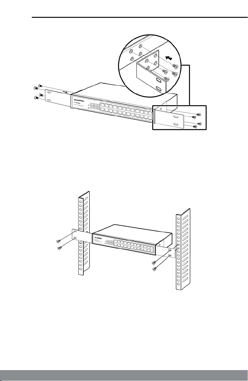
Remove the adhesive backing papers from the rubber feet.
3) Turnover the switch and attach the supplied rubber feet to the
recessed areas on the bottom at each corner of the switch.
9
Page 10
LP-SW2400S ▪ 24-port 10/100Mbps Fast Ethernet Switch ▪ User Guide ▪ www.lanpro.com
Figure 5. Attaching Rubber Feet
4) Upturn the switch and connect it to the network devices while
keep enough ventilation space around.
5) Connect the switch to power source with the provided power
cord.
Caution:
Please avoid any heavy thing placed on the switch.
Rack Installation
3.2.2
To install the switch in an EIA standard-sized, 19-inch rack, follow the
instructions described below:
1) Secure the supplied rack-mounting brackets to each side of
the switch with supplied screws, as illustrated in the following
gure.
10
Page 11
LP-SW2400S ▪ 24-port 10/100Mbps Fast Ethernet Switch ▪ User Guide ▪ www.lanpro.com
Figure 6. Attaching Brackets
2) After the brackets are attached to the switch, use suitable
screws (not provided) to secure the brackets to the rack, as
illustrated in the following gure.
Figure 7. Mounting Switch
3) Connect the switch to network devices.
4) Supply power to the switch with the provided power cord.
11
Page 12
LP-SW2400S ▪ 24-port 10/100Mbps Fast Ethernet Switch ▪ User Guide ▪ www.lanpro.com
Connect to Ground
3.3
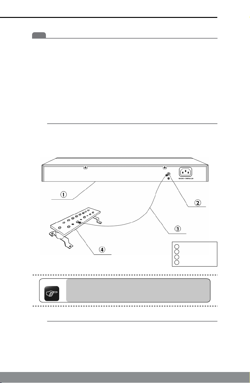
Connecting the switch to ground is to quickly release the lightning overvoltage and over-current of the switch, which is also a necessary measure
to protect the body from electric shock.
In different environments, the switch may be grounded differently. The
following will instruct you to connect the switch to the ground in two ways:
connecting to the Grounding Bar or connecting to the Ground via the power
cord. Please connect the switch to ground in the optimum way according to
your specic operation environment.
• Connecting to the Grounding Bar
If the switch is installed in the equipment room, where a Grounding Bar is
available, you are recommended to connect the switch to the Grounding
Bar as shown in the following gure.
Switch (Rear Panel)
1
Grounding Terminal
2
Ground Cable
3
Grounding Bar
Figure 8. Connecting to the Grounding Bar
4
Note:
The Grounding Bar and Ground Cable are not
provided with our product.
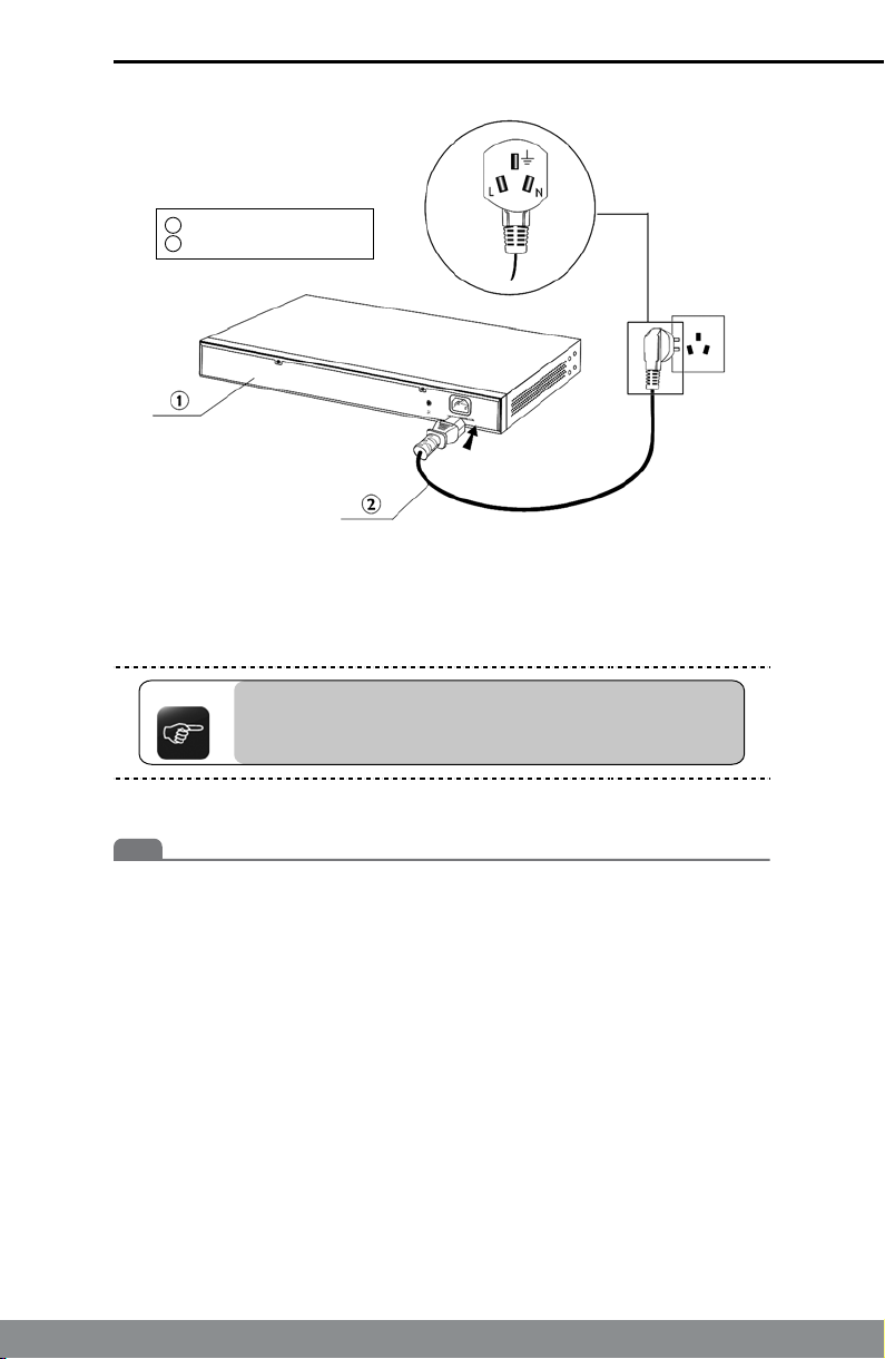
• Connecting to the Ground via the power supply
If the switch is installed in the normal environment, the switch can be
grounded via the PE (Protecting Earth) cable of the AC power supply as
shown in the following gure.
12
Page 13
LP-SW2400S ▪ 24-port 10/100Mbps Fast Ethernet Switch ▪ User Guide ▪ www.lanpro.com
Switch (Rear Panel)
1
AC Power Cord (with PE cable)
2
Figure 9. Connecting to the Ground
*The gure is to illustrate the application and principle. The power plug you get
from the package and the socket in your situation will comply with the regulation
in your country, so they may differ from the gure above.
Note:
If you intend to connect the switch to the ground via the
PE (Protecting Earth) cable of AC power cord, please make
sure the PE (Protecting Earth) cable in the electrical outlet
is well grounded in advance.
Power on
3.4
The LP-SW2400S 24-port 10/100Mbps Fast Ethernet Switch is powered
by an AC Power Supply. Connect the switch and power outlet by power
cord. Powering on the switch, it will be automatically initialized and the LED
indicators should respond as follows:
1) All of the LED indicators will ash momentarily for one second,
which represents a resetting of the system.
2) The Power LED indicator will light up.
13
Page 14
LP-SW2400S ▪ 24-port 10/100Mbps Fast Ethernet Switch ▪ User Guide ▪ www.lanpro.com
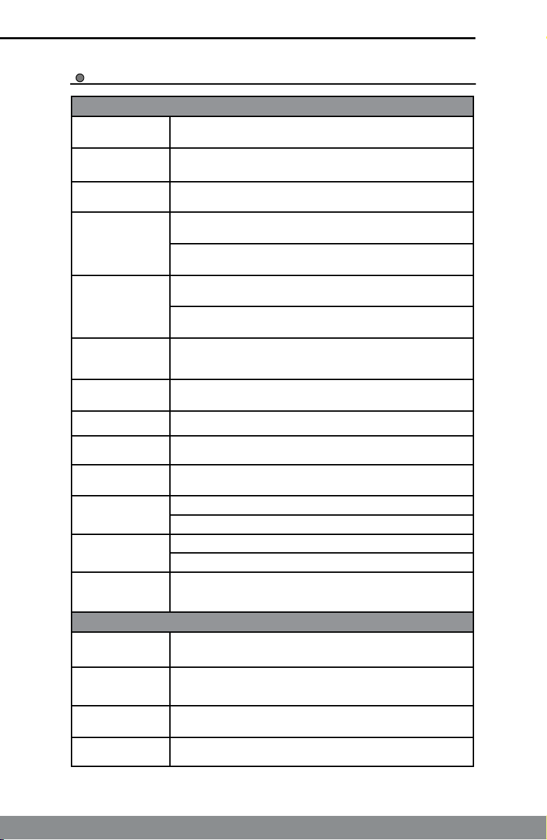
Appendix A: Specications
General
Standards IEEE 802.3, IEEE 802.3u, IEEE802.3az, IEEE 802.1p
Topology Star
Protocol CSMA/CD
Ethernet: 10Mbps (Half Duplex)
Data Transfer
Rate
Network
Media (Cable)
Number of Ports 24 10/100Mbps Auto-Negotiation RJ-45 ports
20Mbps (FullDuplex)
Fast Ethernet: 100Mbps (Half Duplex)
200Mbps (Full Duplex)
10Base-T: UTP category 3, 4, 5 cable (maximum 100m)
EIA/TIA-568 100 STP (maximum 100m)
100Base-TX: UTP category 5, 5e cable (maximum 100m)
EIA/TIA-568 100 STP (maximum 100m)
Safety &
Emissions
LED indicators Power, Link/Act
Transfer Method Store-and-Forward
MAC Address
Learning
Frame Filter
Rate
Frame Forward
Rate
Backbound
Bandwidth
CE
Automatically learning, automatically aging
10Base-T: 14881pps/Port
100Base-Tx: 148810pps/Port
10Base-T: 14881pps/Port
100Base-Tx: 148810pps/Port
4.8 Gbps
Environmental and Physical
Operating
Temperature
Storage
Temperature
Operating
Humidity
Storage Humidity 5%~90% non-condensing
0°C ~40°C (32°F ~104°F)
-40°C ~70°C (-40°F ~158°F)
10%~90% non-condensing
14
Page 15
LP-SW2400S ▪ 24-port 10/100Mbps Fast Ethernet Switch ▪ User Guide ▪ www.lanpro.com
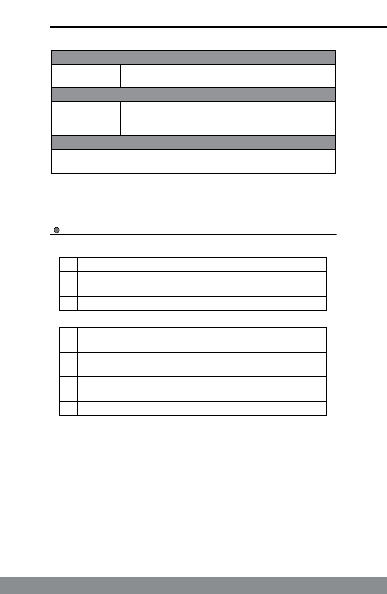
Mechanical
Switch 11.6*7.1*1.7 in. (294*180*44 mm)
Electrical
Power
Specication
110-240V AC, 50-60Hz
Safety And Emission
CE
Appendix B: Troubleshooting
1) The Power LED is not lit
►
Make sure the AC power cord connected the switch with
power source properly.
►
Make sure the power source is ON.
The Link/Act LED is not lit when a device is connected to
2)
the corresponding port
►
Make sure that the cable connectors are rmly plugged into
the switch and the device
►
Make sure the connected device is turned on and working
well.
►
The cable must be less than 100 meters long (328 feet).
15
Page 16
Visit us on:
@lanpronews
Designed and Manufactured under LanPro standards and specications.
LanPro is a member of One Network Alliance Group of Companies.
LanPro products are made in one of the following countries: USA,
China, Taiwan, Thailand and Korea. The exact country of origin is unknown.
LanPro and LanProfessional are US registered brands.
LanPro America: 1880 NW 93rd Av, Doral, Florida 33172, USA.
Main web page: www.lanpro.com Support: [email protected]
LanPro Lan
www.lanpro.com
 Loading...