

Lanpro LP-SGW2400 User Manual

Active Products - Switches
www.lanpro.com
LP-SGW2400 24 ports 10/100/1000
24 ports Remote Web Manageable Smart Switch 10/100/1000 Mbps
SNMP capable
LPSGW2400_UG_ENB01W
LP-SGW2400
24 ports 10/100/1000
24 ports Remote Web Manageable
Smart Switch 10/100/1000 Mbps
SNMP capable.

Chapter 1 Product Specification
A
Thank you for the loyalty you have shown to our company and products. We are sure
the performance and the quality of our devices will be up to your demanding standards.
LanPro provides technical support to your product along its lifetime so you get the most
of your investment.
1.1 Product Characteristics
* Complies with IEEE802.3, IEEE802.3u, IEEE802.3ab standards
*24 10/100/1000M Auto-negotiation RJ45 port, Auto MDI/MDIX function.
*Supports IEEE802.3x flow control for full-duplex, and backpressure flow control for half-duplex.
*48Gbps backplane bandwidth, support Non-blocking wire-speed forwarding.
*Store and forward architecture, integrated 8K MAC address table, meet all the application demands.
*Supports up to 16 VLAN groups for 802.1q VLAN.
*Supports up to 24 trunks with up to 16 ports in a trunk;
*Supports port bandwidth control function.
*Supports QoS function.
*Supports port-based access control support (IEEE 802.1X).
*Supports source IP filter per port to block unwanted access.
*Supports broadcast storm smart control function.
*Supports port mirror.
*Supports Web Smart and console manager.
*Supports HTTP switch system software upgrading, configuration file, backup and reset function.
*Supports circuit diagnoses.
*Supports flow statistic function, dynamic display switch port receiving -transferring data package situation.
*Suports administration via console.
*Inside wide power, 2 Fan Vents for additional redundance, 1U steel case, 19 Inches strong metallic standard
structure design.
Active Products - Switches - LP-SGW2400
1.2 Packing list
Please check the articles included after you open the packing as below:
If any element is remaining, please contact with your distributor. LanPro can supply
spare parts in case you need to repair a damaged unit.
*1 piece 24 ports Ethernet Switch.
*1 piece power cable.
*1 piece console cable.
*1 pair “L” bracket.
*8 pieces screw.
*4 pieces rubber padding.
*1 piece User’s manual.
2
www.lanpro.com

Active Products - Switches - LP-SGW2400
Chapter 2 Hardware Installation
B
2.1 Quick Installation Guide
Choose a proper place for the LP-SGW2400 rack mountable switch, considering the surroundings such as power
requirements, space, keep it away from sunlight, heat source, and electromagnetic interference area. The wind range
must be at least 10 cm (3 inches) for a good ventilation.
Installation & Connection method:
1
Stick the rubber padding to the rear side of the switch.
2
Use standard EIA 19’ rack mount and fix the rack on both sides of the switch.
LanPro has a complete line-up of cabinets, racks and Server racks for all kinds of applications.
3
Adjust the holes so that they can fit and fasten the switch with the turnbuckle.
4
Plug the cable into the switch socket, turn the power on, the switch will test itself, all indicators
and lights are on at the same time, after 5 seconds the lights automatically turn off and test is
done.
5
Put one end of the Cat.5, Cat5e or 6 cable cable into a RJ45 port of the switch, the other end is
connected with the NIC card and router If the power of the switch is on, the related indicators
are on. Every port of the switch can be used as Uplink port.
Note: Don’t plug a phone line into an RJ45 port, otherwise it will damage the unit.
The switch can adjust the power automatically depending on the input voltage range within the
6
marked voltage on the rear board.
2.2 LED Indications
LED Status Indications
Power ON/OFF Power on/off
Link/Act ON/OFF Ports connected/Ports unconnected
FLASH Data frames are through
Speed ON/OFF The transmission rate among ports is 1000Mbps./
Chapter 3 Configuration Guide
C
The transmission rate is 10/100 Mbps.
3.1 Fast Log In
Notice: You must configure IP for the managing PC, because the default parameter of the switch is listed
as below: Default IP address is 192.168.2.1, there is no password. You can log in the switch setting
window through the steps as below:
1
Connect the switch with the managing PC adapter.
2
Turn on the switch power supplier.
3
Make sure the PC IP address belong to 192.168.2.xxx,
e.g:192.168.2.100(xxx is the integer between 2~254).
3
www.lanpro.com

4
Open the browser, input the http://192.168.2.1 and “Enter”
it, you will see the switch login window as below (take 24
Ports Switch as sample), (figure1):
Figure 1
5
Input the Password (default there is no password), then
click the “Apply” and the Configuration window will show
as below:
There are items in the window’s left side, they are:
“Configuration”, “Monitoring” and “Maintenance”. You can
set the relative items according to your demands (the more
detailed guide will be mentioned in the later chapters, will
take the 24Port Switch as sample).
Active Products - Switches - LP-SGW2400
3.2 System
Figure 2
System: Display current switch system situation
and you can set the relative items according to
your demands.
MAC address: Display the current switch MAC address.
Software Version: Display the switch Software version.
Hardware Version: Display the switch hardware version.
Temperature: This item is ineffective.
Active IP Address: 192.168.2.1 (default ).
Active Subnet Mask: 255.255.255.0 (default).
Active Gateway: 0.0.0.0 (default).
DHCP Server: 0 (default).
Lease Time Left: 0 (default).
Figure 3
4
www.lanpro.com
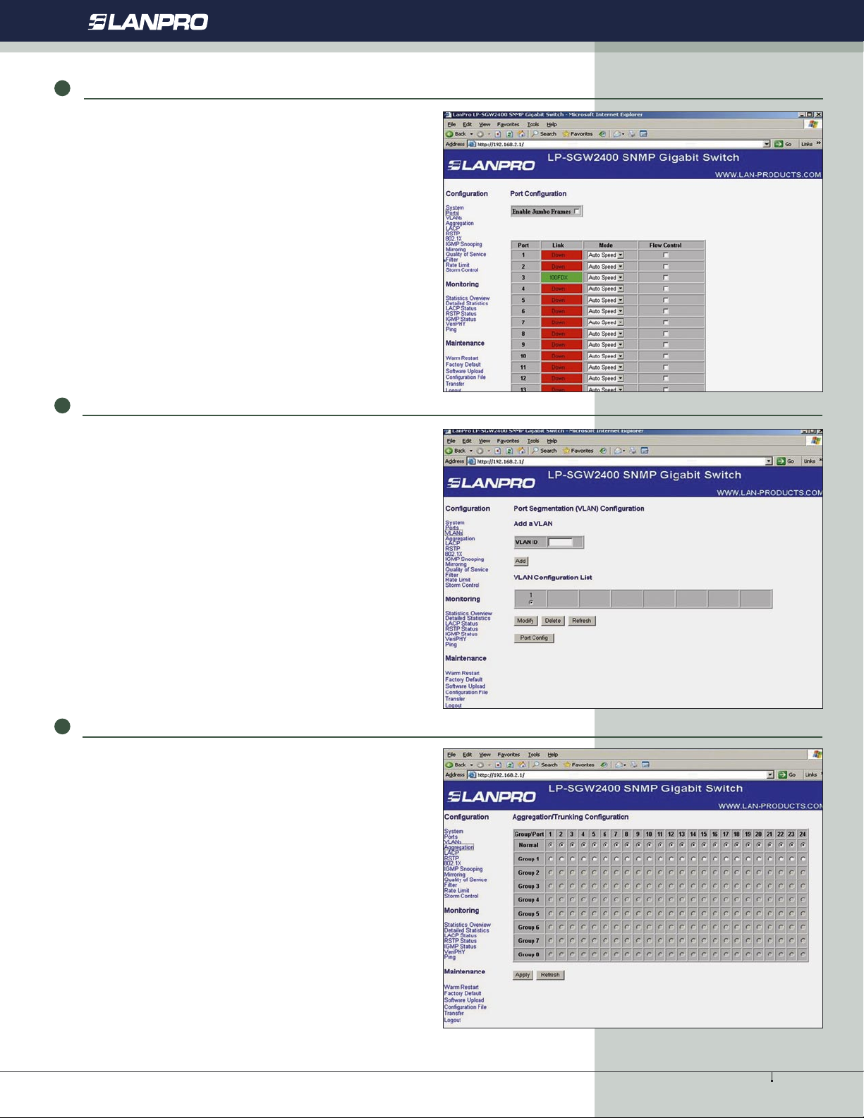
3.3 Ports
Port display Link station and can set each port as: speed,
flow control. Every port can choose one work mode in 7
kinds as below: 10M half-duplex, 10M full-duplex, 100M
half-duplex, 100M full-duplex, 1000M full-duplex, autonegotiation, disable. Default is auto-negotiation. Each port
must choose a best work mode after it is negotiated with the
corresponding object automatically.
Figure 4
3.4 VLANs
Active Products - Switches - LP-SGW2400
Can set 16 VLAN groups for 802.1q VLAN.
VLAN group setting: the port can communicate only when it
is set to the same VLAN goup, a port can belong to a multi
VLAN group, and can communicate with a multi Vlan group
at the same time.
Figure 5
3.5 Aggregation
Aggregation, also called port trunk ismostly used for the
Uplink passage redundancy, an incorrect containerTrunk
group can not span the VLAN, all the trunk members must
be in the same VLAN, otherwise Trunk function will be lost.
You cannot connect the two Trunk groups into each other,
and cannot connect two switches by two Trunk passages.
Any operation of them will make the network cycle and stop
the network.
Figure 6
5
www.lanpro.com
 Loading...