

Page 1
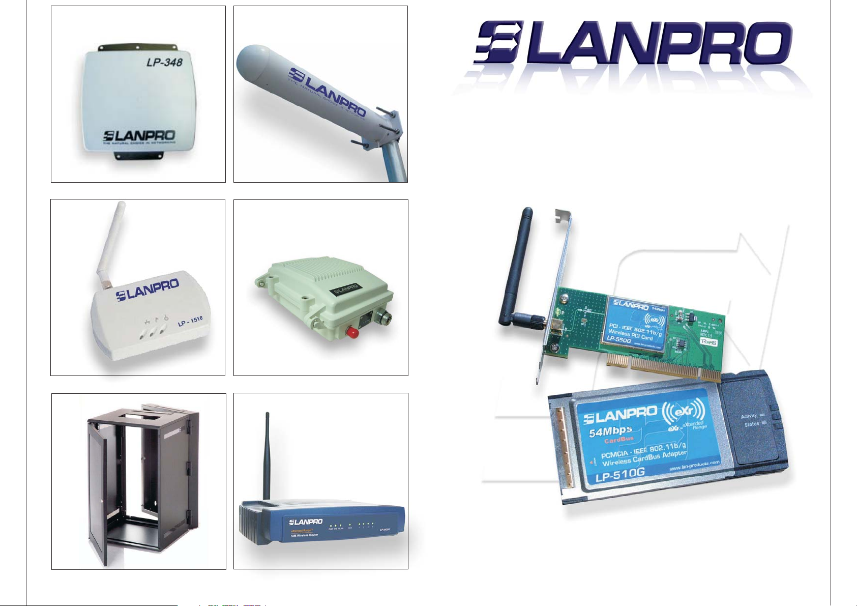
LP-348
LP-1518 LP-5P
LP-Yagy2415
LP-510G/550G
54M Wireless Adapter
PCMCIA/PCI
User Guide
Ver:2.0
LP-5420G
WWW.LANPRO.COM
Page 2

COPYRIGHT & TRADEMARKS
Specifications are subject to change without notice. is a registered trademark of
Lanprofessional. Other brands and product names are trademarks or registered
trademarks of their respective holders.
No part of the specifications may be reproduced in any form or by any means or used to
make any derivative such as translation, transformation, or adaptation without
permission from Lanprofessional. Copyright © 2007 Lanprofessional. All rights reserved.
Package Contents.............................................................................................1
Chapter 1:
Introduction....................................................................................................2
1.1 Overview of the product.......................................................................2
1.2 Features.............................................................................................2
1.3 LED Status..........................................................................................3
1.3.1 LP-510G LED Indications...............................................................3
1.3.2 LP-550G LED Indications...............................................................3
Chapter 2: Installation Guide.............................................................................4
2.1 Hardware Installation...........................................................................4
2.1.1 LP-550G HardwareInstallation........................................................4
2.1.2 LP-510G HardwareInstallation........................................................4
2.2 Software Installation............................................................................4
2.2.1 Overview.....................................................................................4
2.2.2 Software Installation for Windows2000............................................4
Chapter 3: Configuration.................................................................................10
3.1 Current Status...................................................................................10
3.2 Profile Management............................................................................12
3.2.1 Add or Modify a Configuration Profile.............................................12
3.2.2 Remove a profile.........................................................................15
3.2.3 Switch another Profile..................................................................15
3.2.4 Import a Profile..........................................................................16
3.2.5 Export a Profile...........................................................................16
3.2.6 Scan Available Networks..............................................................17
3.2.7 Auto Profile Selection Management................................................17
3.3 Diagnostics.......................................................................................18
3.3.1 Check Driver Information.............................................................19
3.3.2 Check Receive and Transmit Statistica lInformation........................19
Appendix A: Specifications...............................................................................20
Appendix B: Glossary......................................................................................21
Appendix C: Contact Information......................................................................23
Infrastructure Network - An infrastructure network is a group of computers or
other devices, each with a wireless adapter, connected as an 802.11 wireless LAN. In
infrastructure mode, the wireless devices communicate with each other and to a
wired network by first going through an access point. An infrastructure wireless
network connected to a wired network is referred to as a Basic Service Set (BSS). A
set of two or more BSS in a single network is referred to as an Extended Service Set
(ESS). Infrastructure mode is useful at a corporation scale, or when it is necessary to
connect the wired and wireless networks.Spread Spectrum
- Spread Spectrum
technology is a wideband radio frequency technique developed by the military for use
in reliable, secure, mission-critical communications systems. It is designed to trade
off bandwidth efficiency for reliability, integrity, and security. In other words, more
bandwidth is consumed than in the case of narrowband transmission, but the trade
off produces a signal that is, in effect, louder and thus easier to detect, provided that
the receiver knows the parameters of the spread-spectrum signal being broadcast. If
a receiver is not tuned to the right frequency, a spread-spectrum signal looks like
background noise. There are two main alternatives, Direct Sequence Spread
Spectrum (DSSS) and Frequency Hopping Spread Spectrum (FHSS).
SSID - A
Service Set Identification is a thirty-two character (maximum)
alphanumeric key identifying a wireless local area network. For the wireless devices
in a network to communicate with each other, all devices must be configured with the
same SSID. This is typically the configuration parameter for a wireless PC card. It
corresponds to the ESSID in the wireless Access Point and to the wireless network
name. See also Wireless Network Name and ESSID.
WEP
(Wired Equivalent Privacy) - A data privacy mechanism based on a 64-bit or
128-bit or 152-bit shared key algorithm, as described in the IEEE 802.11 standard.
Wi-Fi
- A trade name for the 802.11b wireless networking standard, given by the
Wireless Ethernet Compatibility Alliance (WECA, see http://www.wi-fi.net), an
industry standards group promoting interoperability among 802.11b devices.
WLAN
(Wireless Local Area Network) - A group of computers and associated devices
communicate with each other wirelessly, which network serving users are limited in a
local area.
WPA
(Wi-Fi Protected Access) - A wireless security protocol use TKIP (Temporal Key
Integrity Protocol) encryption, which can be used in conjunction with a RADIUS
server.
Appendix C: Contact Information
For help with the Installation or operation of the LANPRO LP-510G/LP-550G 54M
Wireless Adapter, please contact us.
E-mail: [email protected]
Website: http://www.lan-products.com
1
14
Page 3

Environmetal and Physical
Operating Temp. 0ºC - 40ºC (32ºF-104ºF)
Storage Temp. -40ºC - 70ºC (-40ºF 158ºF)
Humidity 10% - 95% RH, Nom-condensing
Dimensions 4,5x2,1x0,2in. (115x54x5mm) (LP-510G)
(WxDxH) 5,2x4,8x0,9in. (113x121x22mm) (LP-550G)
Appendix B: Glossary
Package Contents
The following contents should be found in your box:
One LP-510G/LP-550G Wireless Adapter
Quick Installation Guide
One Resource CD for LP-510G/LP-550G, including:
• LANPRO Wireless Client Utility (LWCU) and Drivers
• User Guide
• Other Helpful Information
2x to 3x eXtended Range WLAN Transmission Technology
- The WLAN device
with 2x to 3x eXtended RangeTM WLAN transmission technology make its sensitivity up
to 105 dB, which gives users the ability to have robust, longer-range wireless
connections. With this range-enhancing technology, a 2x to 3x eXtended RangeTM based
client and access point can maintain a connection at as much as three times the
transmission distance of traditional 802.11b and 802.11g products, for a coverage area
that is up to nine times greater. A traditional 802.11b and 802.11g product transmission
distance is about 300m, A LANPRO 2x to 3x eXtended RangeTM based client and access
point can maintain a connection transmission distance may be up to 830m.
802.11b
- The 802.11b standard specifies a wireless product networking at 11 Mbps
using direct-sequence spread-spectrum (DSSS) technology and operating in the
unlicensed radio spectrum at 2.4GHz, and WEP encryption for security. 802.11b
networks are also referred to as Wi-Fi networks.
802.11g
- specification for wireless networking at 54 Mbps using direct-sequence
spread-spectrum (DSSS) technology, using OFDM modulation and operating in the
unlicensed radio spectrum at 2.4GHz, and backward compatibility with IEEE 802.11b
devices, and WEP encryption for security.
Ad-hoc Network
- An ad-hoc network is a group of computers, each with a wireless
adapter, connected as an independent 802.11 wireless LAN. Ad-hoc wireless computers
operate on a peer-to-peer basis, communicating directly with each other without the use
of an access point. Ad-hoc mode is also referred to as an Independent Basic Service Set
(IBSS) or as peer-to-peer mode, and is useful at a departmental scale or SOHO
operation.
(Direct-Sequence Spread Spectrum) - DSSS generates a redundant bit pattern for
DSSS
all data transmitted. This bit pattern is called a chip (or chipping code). Even if one or
more bits in the chip are damaged during transmission, statistical techniques embedded
in the receiver can recover the original data without the need for retransmission. To an
unintended receiver, DSSS appears as low power wideband noise and is rejected
(ignored) by most narrowband receivers. However, to an intended receiver (i.e. another
wireless LAN endpoint), the DSSS signal is recognized as the only valid signal, and
interference is inherently rejected (ignored).
(Frequency Hopping Spread Spectrum) - FHSS continuously changes (hops) the
FHSS
carrier frequency of a conventional carrier several times per second according to a
pseudo-random set of channels. Because a fixed frequency is not used, and only the
transmitter and receiver know the hop patterns, interception of FHSS is extremely
difficult.
Note:
If any of the listed contents are damaged or missing, please contact the
retailer from whom you purchased the LP-510G/LP-550G Wireless Adapter for
assistance.
Chapter 1: Introduction
1.1 Overview of the product
The LANPRO 54M Wireless Adapter LP-510G/LP-550G gives you the flexibility to
install your PC or notebook PC in the most convenient location available, without the
cost of running network cables.
The adapter's auto-sensing capability allows high packet transfer rate of up to
54Mbps for maximum throughput, or dynamic range shifting to lower speeds due to
distance or operating limitations in an environment with a lot of electromagnetic
interference. It can also interoperate with all 11Mbps wireless (802.11b) products.
Your wireless communications are protected by up to 152-bit WEP and WPA
encryption for high security.
It adopts 2x to 3x eXtended RangeTM WLAN transmission technology so that
transmission distance is 2-3 times of traditional 11g/b solutions, up to 855.36m
tested in China. Transmission range is extended to 4-9 times.
1.2 Features
Complies with IEEE802.11g, IEEE802.11b standards
Adopts 2x to 3x eXtended RangeTM wireless LAN transmission technology
Supports WPA/WPA2 data security, IEEE802.1x authentication, TKIP/AES
encryption, 64/128/152-bit WEP encryption
Supports 54/48/36/24/18/12/9/6Mbps or 11/5.5/3/2/1Mbps wireless LAN data
transfer rates
Provides 32-bit PCI interface (LP-550G) or 32-bit CardBus interface (LP-510G)
Supports Ad-Hoc and Infrastructure modes
Supports roaming between access points when configured in Infrastructure mode
Ease to configure and provides monitoring information
Supports Windows 2000, XP
Internal Antenna (LP-510G)
13
2
Page 4

1.3 LED Status
1.3.1 LP-510 LED Indications
LED Indications Status Working Status
Status Green Intermittently The Adapter is in an electricity saving status
Activity Green Not lit
Status Green Lit The adapter is on wake up status
Activity Green Not lit
Status Green Flashing The adapter is trying to scan a networking
Alternately connection.
Activity Green Flashing
Alternately
Status Green Intermittently The adapter is already connected but is not
Activity Green Intermittently transmiting or receiving data
Status Green Flashing The adapter is transmiting or receiving data
Activity Green Flashing
1.3.2 LP-550 LED Indications
LED Indications Status Working Status
Status Intermittently The adapter is in an electricity saving status or
the adapter is already connected but is not
transmitting or receiving data
Status Green Lit The adapter is on wake up status.
Status Green Flashing The adapter is transmitting and receiving data
Chapter 2: Installation Guide
3.3.1 Check Driver Information
The Adapter Information contains general information about the wireless network
adapter and the Network Driver Interface Specification (NDIS) driver. Access the
adapter information from the Diagnostics tab.
Card Name - The name of the wireless network adapter.
MAC Address - The MAC address of the wireless network adapter.
Driver - The driver name and path of the wireless network adapter driver.
Driver Version - The version of the
wireless network adapter driver.
Driver Date - The creation date of the
wireless network adapter driver.
Client Name - The name of the client
computer.
3.3.2 Check Receive and Transmit
Statistical Information
The Advanced Statistics show receiving
and transmitting statistical information
for the following receive and transmit
diagnostics for frames received by or
transmitted to the wireless network
adapter.
Figure 3-13 Advanced Statistics
2.1 Hardware Installation
2.1.1 LP-550G Hardware Installation
To install the adapter, follow these steps listed below:
1. Turn off your desktop PC and disconnect the power.
2. Open your PC case and locate an available PCI slot on the motherboard. Remove the
metal slot cover on the back of the PC. Check with your computer manufacturer for
instructions if needed.
3. Slide the PCI Adapter into the PCI slot. Make sure that all of its pins are touching the
slot's contacts. Once the adapter is firmly in place, secure its fastening tab to your PC's
chassis with a mounting screw. Then, close your PC case.
4. Reconnect your PC's power and turn on your desktop PC.
2.1.2 LP-510G Hardware Installation
To install the adapter, follow these steps listed below:
1. Locate an available CardBus slot on your laptop.
2. With the connector pin end facing the CardBus slot and the label facing up, slide the
Adapter into the CardBus slot until it locks in place.
3. The Status LED should Intermittent flashing when the Adapter is installed correctly.
Appendix A: Specifications
Normal
Interface LP-510G: 32-bit CardBus
LP-550G: 32-bit PCI
Standards IEEE802.11b; IEEE802.11g
Operating System Windows 2000, XP
Tansmission Indoor up to 100m, outdoor up to 300m (Standard
transmission
Range WLAN transmission technology, it is limited to the
Distance environment)
extended
Radio Data Rate 54/48/36/24/18/12/9/6/ Mbps or 11/5,5/3/2 Mbps. (Auto
Rate
Sensing)
Modulation 1M DBPSK; 2M DQPSK; 5,5M, 11M CCK; 6M, 9M, 12M, 18M,
24m
36M, 48M, 54M , OFDM;
Media Acces CSMA/CA with ACK
Protocol
Transmit Power 18dB (Typical)
Data Security WPA/WPA2; 64/128//152-bit WEP, TKIP/AES
Frequency 2,4 - 2,4835GHz
3
Spread Spectrum Direct Sequence Spread Spectrum (DSSS)
12
Page 5
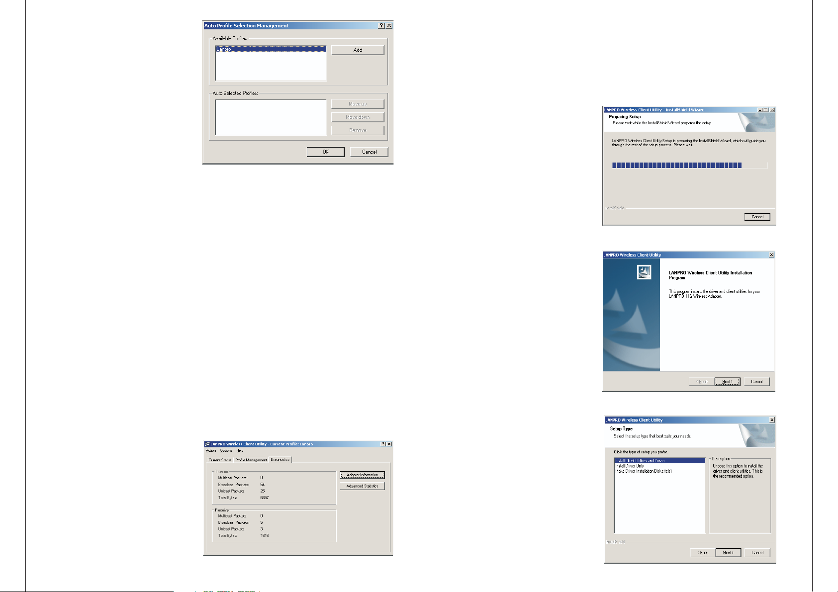
3.2.7 Auto Profile Selection
Managemen
The auto selection feature allows
the wireless adapter to automatically select a profile from
the list of profiles and use it
to connect to the network.
To add a new profile into the Auto
Selected Profiles list, please
follow these steps.
1. On the Profile Management tab,
click Order Profiles
2. The Auto Profiles Selection
management window will appear,
Figure 3-11 Auto Profile Selection Management Dialog
with a list of all created profiles in the Available Profiles box.
2.2 Software Installation
2.2.1 Overview
The Adapter's Setup Wizard will guide you through the Installation procedure for
Windows 2000, XP. The Setup Wizard will install the LANPRO Wireless Client Utility
(LWCU) and drivers.
When you install the hardware before installing the software, the system will prompt
"Found New Hardware Wizard", click Cancel, and run the Setup Wizard program on
the CD-ROM.
The Setup steps for Windows 2000
and XP are very similar. The following
setup steps are for Windows 2000.
2.2.2 Software Installation for
Windows -2000
3. Highlight the profiles to add to auto profile selection, and click Add. The profile
will appear in the Auto Selected Profiles box.
4. Highlight a profile in the Auto Selected Profiles box.
5. Click Move Up or Move Down as appropriate. Note: The first profile in the Auto
Selected Profiles box has highest priority, and the last profile has lowest priority.
6. Click OK.
7. Check the Auto Select Profilescheckbox on the Profile Management tab.
Note:
When auto profile selection is enabled by checking Auto Select Profiles on the
Profile Management tab, the client adapter will scan for anavailable network. The
profile with the highest priority and the same SSID as one of the found networks will be
used to connect to the network. If the connection fails, the client adapter will try the
next highest priority profile that matches the SSID until an available network is found.
3.3 Diagnostics
The Diagnostics tab of the LANPRO Wireless Client Utility (LWCU) provides buttons
used to retrieve receiving and transmitting statistics. The Diagnostics tab does
not require any configuration. The Diagnostics tab lists the following receive and
transmit diagnostics for frames received or transmitted by the wireless network
adapter:
Multicast frames transmitted and
received
Broadcast frames transmitted and
received
Unicast frames transmitted and
received
1. Insert the Resource CD into your
CD-ROM drive, click Start and choose
Run. In the field that appears,
enter F:\LP-510G_550G\Win2000_XP
\Setup.exe(if "F" is the letter of your
CD-ROM drive), figure 2-1 should
then appear.
2. You can click Cancel to end the installation on the Preparing Setup
screen, figure 2-1. Otherwise, the
Setup Wizard will display a screen
similar to that shown in figure 2-2
after a moment.
3. To continue, click Next on the screen,
figure 2-2 Click Cancel to end the
Installation.
4. The Setup Wizard will ask you to
choose a Setup type in figure 2-3.
It is recommended that you select
Install Client Utilities and Driver. Select
Install Driver Only to install driver
only, select Make Driver Installation
Diskette(s) to make the diskette(s)
as the installation driver. Select
Install Client Utilities and Driver
and click Next to continue the
Figure 2-1 LANPRO Wireless Client Utility - Install Shield
Wizard
Figure 2-2 LANPRO Wireless Client Utility Installation
Program
Total bytes transmitted and received
Figure 3-12 Diagnostics tab
11
Figure 2-3 Select the setup type.
4
Page 6
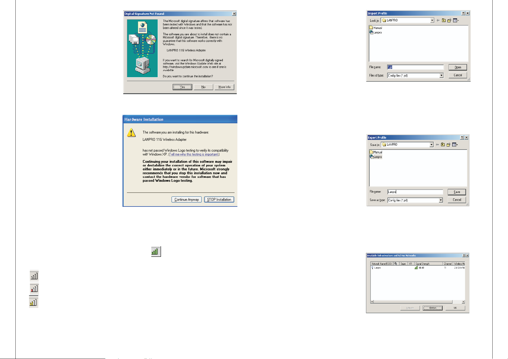
9. While files are copying, you will
see a warning box, shown in figure
2-8. Please select YES to continue
installation. Our drivers have been
tested thoroughly, able to
and are
work with the operating system.
: In Windows XP, the warning
Note
box is similar to that shown figure
2-8a, Please select Continue
Anyway to continue installation.
3.2.2 Remove a profile
1. Go to the Profile Management tab.
2. Select the profile name to remove
in the Profiles List.
3. Click Remove.
3.2.3 Switch another Profile
1.
Go to the Profile Management tab.
Figure 3-8 Import Profile Dialog
Figure 2-8 Widows 2000 Warning Box
10. After the files have been
successfully copied, the screen in
figure 2-9 will appear. Click Finish
to reboot the system.
Chapter 3: Configuration
Figure 2-9 Finish
LANPRO Wireless Adapter LP-510G/LP-550G can be configured by LANPRO Wireless
Client Utility (LWCU). This chapter describes how to configure your LANPRO Wireless
Adapter for wireless connectivity on your Wireless Local Area Network (WLAN) and use
the data security encryption features.
After Installing the Adapter, the Adapter's tray icon will appear in your system tray.
It appears at the bottom of the screen, and shows the signal strength using color and
the received signal strength indication (RSSI).
If the icon is gray, there is no connection.
If the icon is red, there is poor signal strength and the RSSI is less than 5dB.
If the icon is yellow, there is poor signal strength and the RSSI is between 5dB
and 10dB.
2. Click on the profile name in the Profiles List.
3. Click Activate.
3.2.4 Import a Profile
1. From the Profile Management tab, click Import…The Import Profile will then
appear.
2. Browse to the directory where the
profile is located.
3. Highlight the profile name.
4. Click Open, the imported profile will then
appear in the Profiles List.
3.2.5 Export a Profile
1. From the Profile Management tab,
Figure 3-9 Export Profile Dialog
highlight the profile to export.
2. Click Export…, the Export Profile window
will then appear.
3. Browse the directory to export the profile to
.
4. Click Save. The profile should then be exported to the specified location.
3.2.6 Scan Available Networks
1. Click Scan on the Profile Management,
the Available Infrastructure and Ad
Hoc Networks window will appear.
2. Click Refresh to refresh the list at
any time.
3. Highlight a network name and
Figure 3-10 Scan Available Networks Dialog
click Activate to connect an available
network. If no configuration profile
exists for that network, the Profile
5
10
Page 7
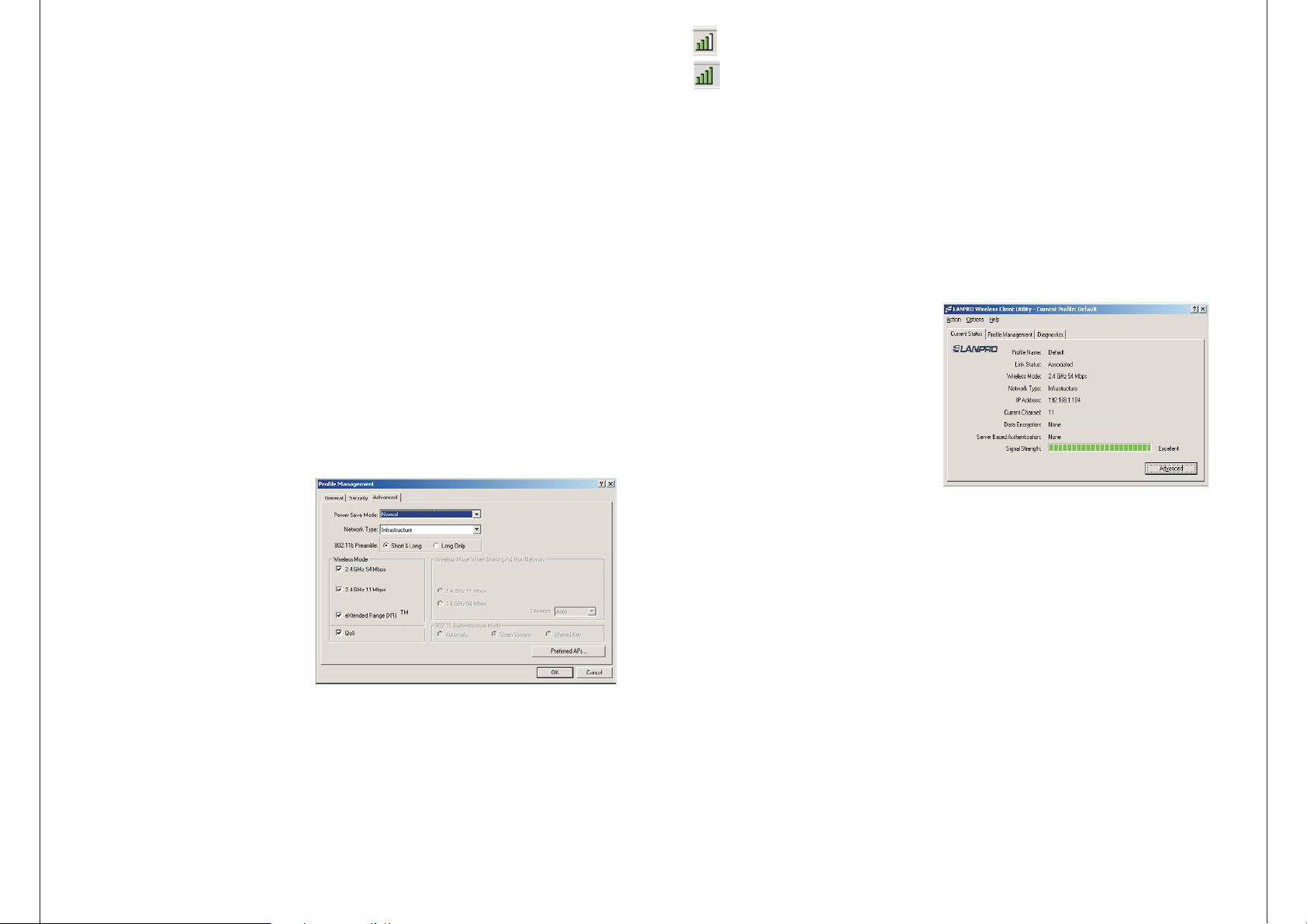
3. Edit the Advanced tab
Power Save Mode -
Maximum
• - Selects maximum mode to let the access point buffer incoming messages
for the wireless adapter. The adapter will detect the access point if any messages are
waiting periodically.
Normal
• - In Normal mode, the adapter will be switched to maximum mode
automatically when no large packets are retrieved
.
Off
• - turns power saving off, thus powering up the wireless adapter continuously for a
short message response time.
802.11b Preamble: Specifies the preamble setting in 802.11b. The default setting is
Short & Long (access point mode), which allows both short and long headers in the
802.11b frames. The adapter can only use short radio headers if the access point
supports and uses them. Set to Long Only to override allowing short frames.
If the icon is green, there is good signal strength and the RSSI is between 10dB
and
20dB.
If the icon is green, there is excellent signal strength and the RSSI is more
than 20dB.
Double-click the icon and the LWCU will run. You can also run the utility by clicking the
Start>Program>LANPRO>LANPRO Wireless Client Utility. The LWCU provides a
complete and easy to use set of tools to:
Display current status information
Edit and add configuration profiles
Display current diagnostics information
The section below introduces these above capabilities.
Wireless Mode:
Specifies 2.4 GHz 54 Mbps or 2.4 GHz 11 Mbps operation in an access
point network. The wireless adapter must match the wireless mode of the access point
with which it associates.
Wireless Mode
when Starting an Ad Hoc Network: Specifies 2.4 GHz 54/11 Mbps to
start an Ad Hoc network if no matching network name is found after scanning all
available modes. This mode also allows the selection of the channel the wireless adapter
uses. The channels available depend on the regulatory domain. If the adapter finds no
other ad hoc adapters, the channel that the adapter starts the ad hoc network with will
be selected automatically. The wireless adapter must match the wireless mode and
channel of the clients it associates.
802.11 Authentication Mode: Select
which mode the wireless adapter uses
to authenticate to an access point:
• Automatic
causes the adapter to
attempt authentication using shared,
but switches it to open authentication
if shared fails.
• Open System
enables an adapter to
attempt authentication regardless of
its WEP settings. It will only associate
with the access point if the WEP keys
on both the adapter and the access
Figure 3-7 Advanced tab of Profile Management
point match.
• Shared-key
only allows the adapter
to associate with access points that
have the same WEP key.
For infrastructure (access point) networks, click Preferred APs… to specify up to four
access points to the client adapter that attempt to be associated to the access
points.
3.1 Current Status
The Current Status tab contains
general information about the
program and its operations. The
Current Status tab does not require
any configurations.
Figure 3-1 Current Status
The following table describes the items found on the Current Status
screen.
• Profile Name - The name of current selected configuration profile. Set up the
configuration name on the General tab of Profile Management.
• Link Status - Shows whether the station is associated to the wireless network.
• Wireless Mode - Displays the wireless mode. Configure the wireless mode on the
Advanced tab of Profile Management.
• Network Type - The type of network and the station currently connected. The
options include:
Infrastructure (access point)
•
Ad Hoc
•
9
6
Page 8
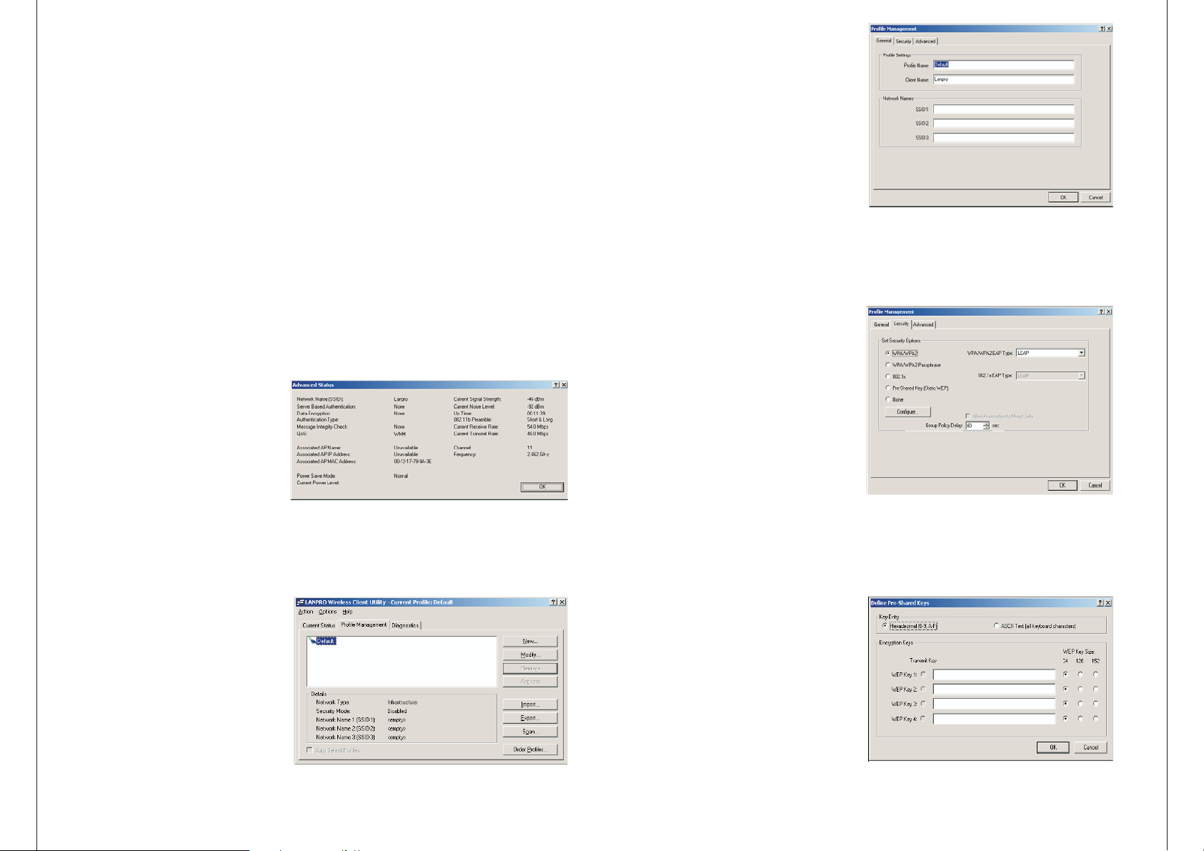
Configure the network type on the Advanced tab of Profile Management.
1. Edit the General tab
IP Address
Current Channel
Data Encryption
- Displays the computer's IP address.
- Shows the currently connected channel.
- Displays the encryption type the driver is using. Configure the
encryption type on the Security tab of Profile Management.
Server Based Authentication
Signal Strength
Note Security Advanced
: In the LWCU, access the General tab, tab and tab by clicking
New Modify
or on the Profile Management tab.
- Shows the strength of the signal.
- Shows whether server based authentication is used.
Click Advanced to see advanced information about the program and its operations. For
more information, please refer to the help file of the utility.
3.2 Profile Management
Click the Profile Management tab of the LWCU and the Profile Management screen
will appear, figure 3-3. The Profile Management screen provides tools to:
Add a profile
Edit a profile
Figure 3-2 Advance Status
Remove a profile
Switch to another Profile
Import a Profile
Export a Profile
Scan Available Networks
Order profiles
3.2.1 Add or Modify a Configuration
Profile
To add a new configuration profile, click New on the Profile Management tab. To
modify a configuration profile, select the configuration from the Profile list and click
Modify.
Figure 3-3 Profile Management tab
The Profile Management dialog box
7
Profile Name - Identifies the configu
ration profile. This name must be
unique. Profile names are not casesensitive.
Client Name - Identifies the client
machine.
Network Names (SSIDs) - The IEEE
802.11 wireless network name. This
field has a maximum limit of 32
characters.
2. Edit the Security tab
•Edit the fields in the Security tab of
Profile Management to configure the
profile. To define the security mode,
select the radio button of the desired
security mode.
• Wi-Fi Protected Access
WPA/WPA2:
• Passphrase: Wi-Fi
WPA/WPA2
Protected Access Passphrase
• Enables 802.1x security.
v802.1x:
• (Static WEP): Enables
Shared Key
use of shared keys that are
the
defined on both the access point
and thestation. To define shared
encryption keys, choose the Shared
Key radio button and click Configure
to fill in the Define Shared Keys
window.
None
: No security (not recommended).
Note
: If the access point that the
wireless adapter associating has
to
WEP set to Optional and the client has
WEP enabled, make sure that Allow
Association to Mixed Cells is checked
on the Security Tab to allow
association. To complete WEP
encryption configuration, you must
select the 802.11 Authentication
Figure 3-4 General Tab of Profile Management
Figure 3-5 Security tab of Profile Management
Figure 3-6 Define Shared Keys
8
 Loading...