

Lanner LVC-2001 User Manual

In-Vehicle Computing
Hardware Platforms for mobile applications
LVC-2001
Preliminary
User's Manual
Release Date: 2015/06/30
Overview
Icon Descriptions
The icons are used in the manual to serve as an
indication of interest topics or important messages.
Below is a description of these icons:
NOTE: This check mark indicates
that there is a note of interest and is
something that you should pay special
attention to while using the product.
WARNING: This exclamation point
indicates that there is a caution or
warning and it is something that could
damage your property or product.
Online Resources
The listed websites are links to the on-line product
information and technical support.
Resource Website
Lanner http://www.lannerinc.com
Product Resources http://assist.lannerinc.com
RMA http://eRMA.lannerinc.com
Copyright and Trademarks
This document is copyrighted, © 2014. All rights are
reserved. The original manufacturer reserves the right to
make improvements to the products described in this
manual at any time without notice.
No part of this manual may be reproduced, copied,
translated or transmitted in any form or by any means
without the prior written permission of the original
manufacturer. Information provided in this manual
is intended to be accurate and reliable. However, the
original manufacturer assumes no responsibility for its
use, nor for any infringements upon the rights of third
parties that may result from such use.
Acknowledgement
Intel, Pentium and Celeron are registered trademarks of
Intel Corp.
Microsoft Windows and MS-DOS are registered
trademarks of Microsoft Corp.
All other product names or trademarks are properties of
their respective owners.
Compliances and Certification
CE Certication
This product has passed the CE test for environmental
specifications. Test conditions for passing included
the equipment being operated within an industrial
enclosure. In order to protect the product from being
damaged by ESD (Electrostatic Discharge) and EMI
leakage, we strongly recommend the use of CEcompliant industrial enclosure products.
FCC Class A Certication
This equipment has been tested and found to comply
with the limits for a Class A digital device, pursuant
to Part 15 of the FCC Rules. These limits are designed
to provide reasonable protection against harmful
interference when the equipment is operated in a
commercial environment. This equipment generates,
uses and can radiate radio frequency energy and, if not
installed and used in accordance with the instruction
manual, may cause harmful interference to radio
communications. Operation of this equipment in a
residential area is likely to cause harmful interference
in which case the user will be required to correct the
interference at his own expense.
e Mark Certication
E13 - Luxembourg

Mechanical compliance
Vibration:
General Vibration (operating): Refer to MIL-STD-810G, •
Method 514.6, Procedure I (Transportation), Category
4 – Common carrier (US highway truck vibration
exposure)
General Vibration (non-operating): Refer to MIL-STD- •
810G, Method 514.6, Procedure I (Transportation),
Category 24 – General minimal integrity
Shock:
Operating (Functional Test for Ground Equipment): •
Refer to MIL-STD-810G, Method 516.6, Procedure I,
40g, 11ms
Non-Operating (Crash Hazard Shock Test for Ground •
Equipment): Refer to MIL-STD-810G, Method 516.6,
Procedure V, 75g, 11ms
Electrical transient conduction along supply lines only
(12V/24V)
Revision History
0.1 2015/06/15 Preliminary
0.2 2015/06/30 Revised specifications
Added vibration a n d
wallmount drawings
Modified hardware setup

Chapter 1: Introduction 5
System Specifications 5
Package Contents 6
Ordering Information 6
Chapter 2: System Components 7
Mechanical Drawings 7
Block Diagram: The MainBoard 10
Front Components 11
Rear Components 12
Chapter 3: Motherboard Information 13
Connectors and Jumpers 13
Add-on Card: LVK-MSDM 15
Connectors and Jumpers List 16
Jumper Settings 17
Connectors 17
Chapter 4: Hardware Setup 24
Preparing the Hardware Installation 24
Installing Memory Module 24
Installing Full-sized Mini-PCIe Module 24
Installing mSATA Storage Device 25
Installing Half-sized Mini-PCIe Module 25
Installing a SATA/mSATA Storage Device 25
Connecting Power 26
Chapter 5: The Flow Chart 27
Appendix A: Using the Ignition System Manager (ISM) 28
Appendix B: Digital Input/Output 29
Appendix C: Accessing the GPS Data from the LVC-2001 35
Appendix D: Programming System Watchdog Timer 37
Appendix E : Terms and Conditions 41
Table of Contents
Chapter 1:
Introduction
Thank you for choosing LVC-2001. The fanless Box PC is
an ideal vehicle gateway controller. LVC-2001 is built with
Intel® Atom™ E3845/E3825 CPU, that supports 4 processor
cores and operates with DDR3L SO-DIMM memory up
to 4GB. The compact and fanless form factor make it
suitable for vehicle applications. Regarding environmental
reliability, LVC-2001 is certied with MIL-STD-810G
vibration and shock resistance. As a vehicle computing
system, LVC-2001 is designed with GPS and G-sensor I/O
for navigation purpose. Other useful I/Os include 2 x RJ-45
LAN ports, 3 mini-PCIe expansion slots with 4 SIM card
sockets, 2 serial ports, 1 optional CAN bus, 2 USB ports and
+9~36VDC power input.
Features:
Intel• ® Atom™ E3845 / E3825 CPU
1 x DDR3L SODIMM max up to 4 GB memory•
2 x Intel® 10/100/1000 Mbps RJ-45 ports•
2 x full-size mini-PCIe slots and 1 x half-size mini PCIe •
slot with total 4 external accessible SIM slots support
Wi-Fi/3G/4G(LTE)/mSATA
MIL-STD-810G vibration/shock resistance•
Display: 1 x VGA and 1 x HDMI•
USB: 1 x USB 3.0 type-A and 1 x USB 2.0 type-A•
Onboard GPS receiver module and G-sensor •
COM ports: 2 x RS-232/422/485 with RI/5V/12V•
Optional: CAN bus support J1939 / J1708 •
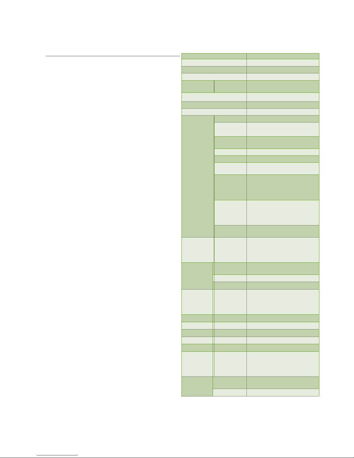
System Specifications
Dimensions
198 x 52 x 185 (mm, the unit)
Processor Intel® BayTrail E3845/E3825
System Memory DDR3L SO-DIMM x1 (up to 4GB)
BIOS AMI SPI Flash BIOS
Storage mSATA/SATA
1 x mSATA socket
1 x SATA 2.5” 9.5 mm drive bay
Ethernet Controller 2 x Intel® i210-IT
Graphic Controller
Intel HD Graphics
Audio Mic IN/Line OUT
I/O
LAN 2 x RJ45 at 10/100/1000 Mbps
Display
1 x VGA
1 x HDMI
Serial I/O
COM1/2: 2 x DB9 RS-232/422/485
with RI/5V/12V
GPS u-blox NEO-7N
G-sensor ADXL 345
USB
1 x USB 3.0 Type A
1 x USB 2.0 Type A
Power Input
3-pin terminal block (+,-,ignition),
+9~36VDC,
ATX mode support ignition delay
on/ off control
Expansion
2x Full-size mini-PCIexpress socket
(1x USB+PCIe+2xSIM; 1x USB+2
x SIM )
1x half-size mini-PCIexpress socket
CAN bus
supports J1939 & J1708, (module
optional)
MIO
4x DI (5V or 12V TTL selectable)
4x DO (12V TTL , Max. 100mA)
2x MCU DI
1x 12V Output @Max. 1A
Power
Input
3-pin terminal block (+,-,ignition),
+9~36VDC,
Output 12V/1A DC out
Adaptor Optional
Environment
Operating
Temperature
-20~60°C (with industrial-grade
components)
-5~45°C (without industrial-grade
components)
Humidity 5% ~ 95%, non-condensing
Mechanical System Design Fanless
Weight 1.8 kg
Mounting Wallmount or suspension kit
Certication EMC CE/FCC Class A, E13, RoHS
Reliability Compliance
Vibration: MIL-STD-810G, Method
514.6
Shock: MIL-STD-810G, Method
516.6
OS Support
Windows
Windows: WES7 (WS7E) / W7 Pro
SP1 / WE8 STD
Linux Linux Kernel 2.6.18 or later

Package Contents
Your package contains the following items:
- LVC-2001 Fanless Embedded System
- Power connector 3 pin x1 (P/N:04AW20031E001)
- HDD Screws x 4 (P/N: 070W102400602)
- Mini-PCIe Screws x 8 (P/N: 070W101000401)
- MIO connector 16pin x1 (P/N: 04AW20161Z101)
Ordering Information
LVC-2001-A1 Intel® Atom SoC E3845 CPU In-Vehicle
Computer, 1 x DDR3L SODIMM, Mini-PCIe
x3, USB 3.0 host x 1, USB 2.0 host x1, Serial
port x2, Optional CAN Bus x1, DC Power
input +9~36Vdc with Ignition
LVC-2001-A2 Intel® Atom SoC E3825 CPU In-Vehicle
Computer, 1 x DDR3L SODIMM, Mini-PCIe
x3, USB 3.0 host x 1, USB 2.0 host x1, Serial
port x2, Optional CAN Bus x1, DC Power
input +9~36Vdc with Ignition
Chapter 2:
System Components
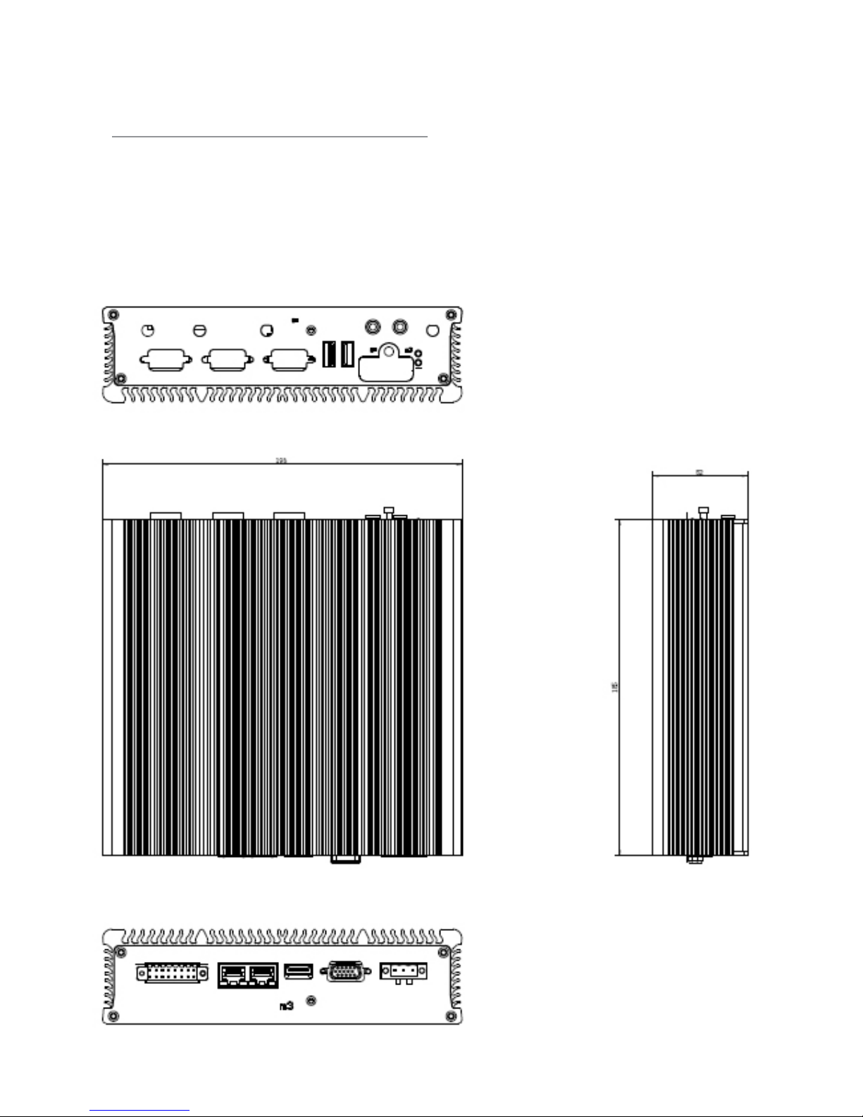
Mechanical Drawings
Mechanical dimensions of the LVC-2001 with the system
itself
Unit: mm
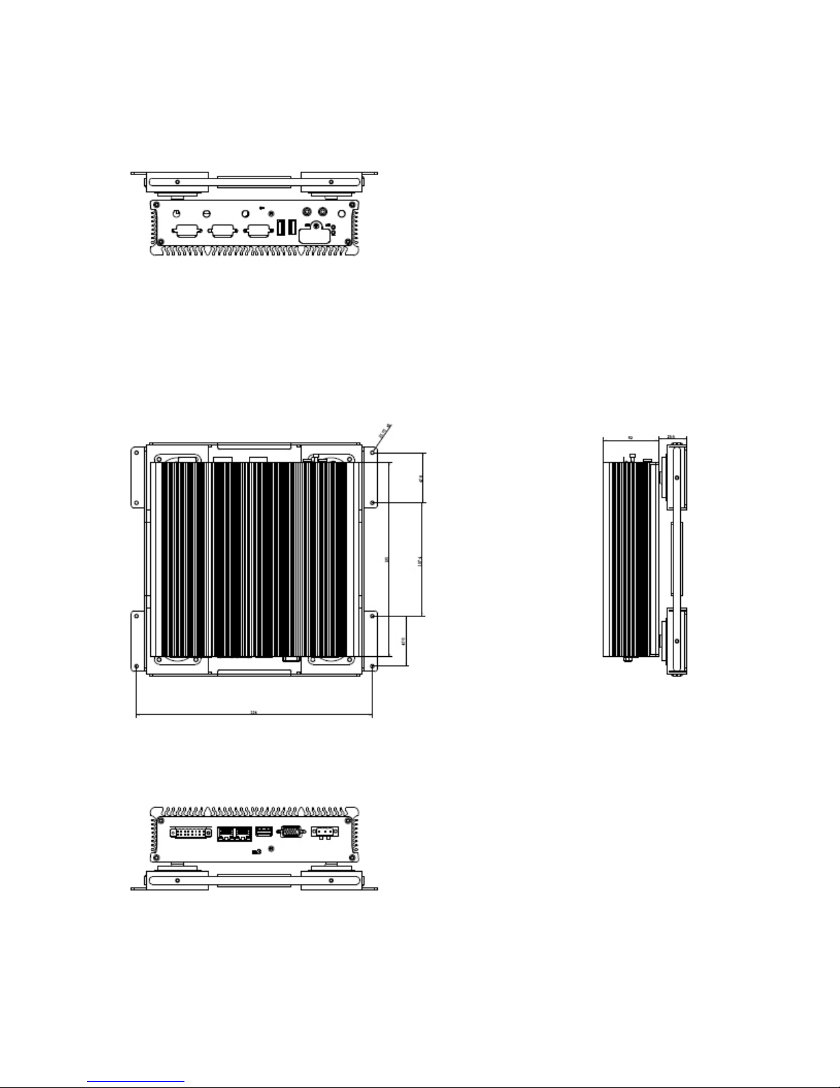
Mechanical dimensions of the LVC-2001 with vibration kit
Unit: mm
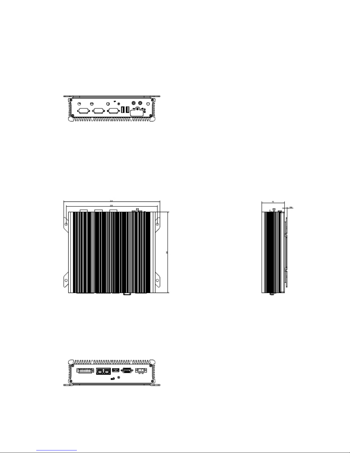
Mechanical dimensions of the LVC-2001 with wallmount kit
Unit: mm
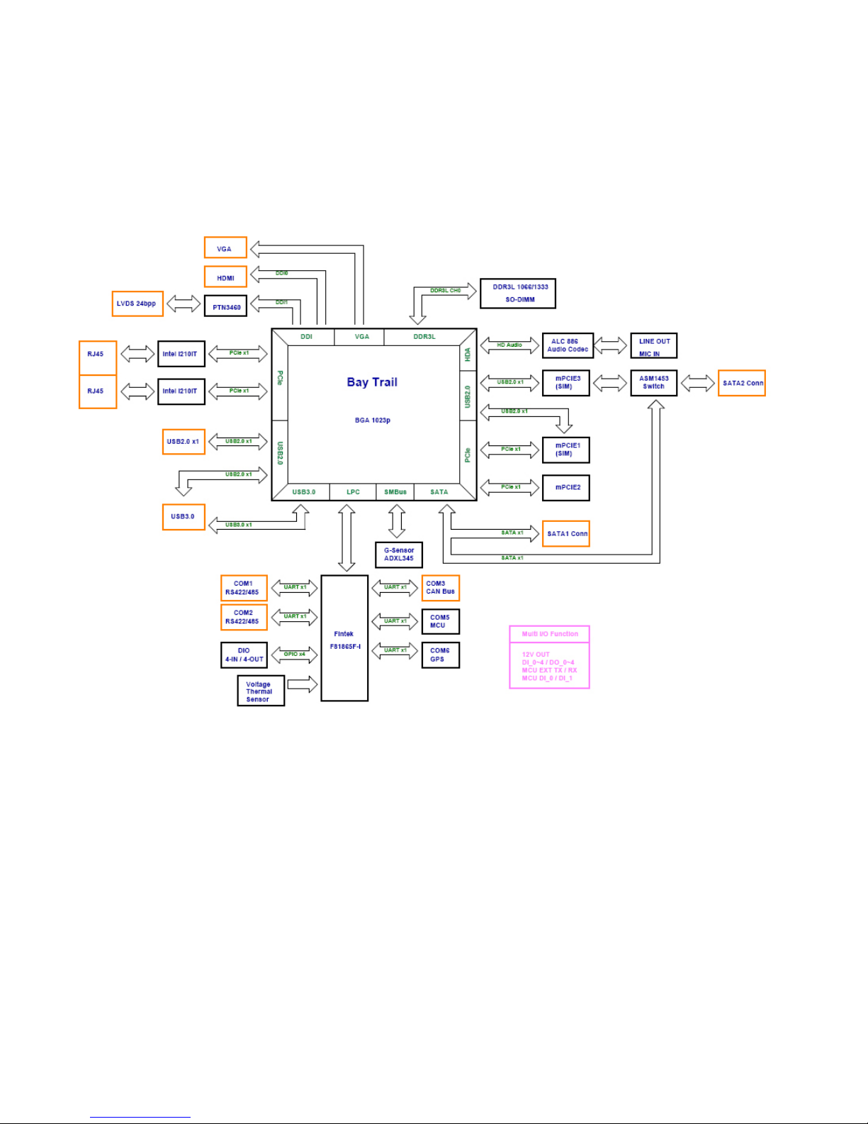
Block Diagram: The MainBoard
The block diagram depicts the relationships among the
interfaces and modules on the motherboard.
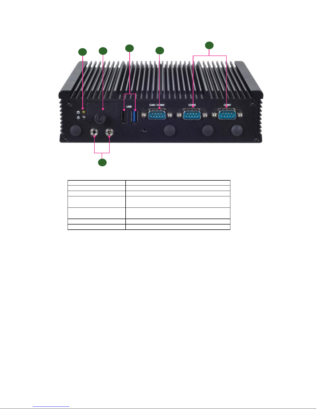
Component Description
F1 LED
Power and HDD/SSD LED
F2 SIM SIM card socket access with cover and lock-screw
F3 USB 1x USB 3.0 type A connector
1 x USB 2.0 type A connector
F4 CAN An optional CAN bus supports J1939 &J1708
standards
F5 COM1/COM2 RS-232/422/485 ports for serial communication
F6 Audio Mic IN/Line OUT
Front Components
F1
F2
F3
F4
F5
F6

Rear Components
Component Description
R1 Multiple-I/O Connector A 16-pin male connector for the following functions:
4x DI (5V or 12V TTL selectable)
4x DO (12V TTL , Max. 100mA)
2x MCU DI
1x 12V Output @Max. 1A
R2 Two 10/100/1000Mbps LAN
ports
Two RJ-45 (provided by Intel i210IT) jacks with LED
indicators as described below
LINK/ACT (Yellow)
On/Flashing: The port is linking and active in data •
transmission.
Off: The port is not linking.•
SPEED (Green/Amber)
Amber: The connection speed is 1000Mbps.•
Green: The connection speed is 100Mbps•
Off: The connection speed is 10Mbps.•
R3 HDMI Port 1 x HDMI display port
R4 VGA Port 1 x VGA display port
R5 Power-Input (DC) 3-pin terminal block (+,-,ignition), +9~36VDC, ATX
mode support ignition delay on/ off control
R3
LINK/ACT
SPEED
R1
R2
R4
R5
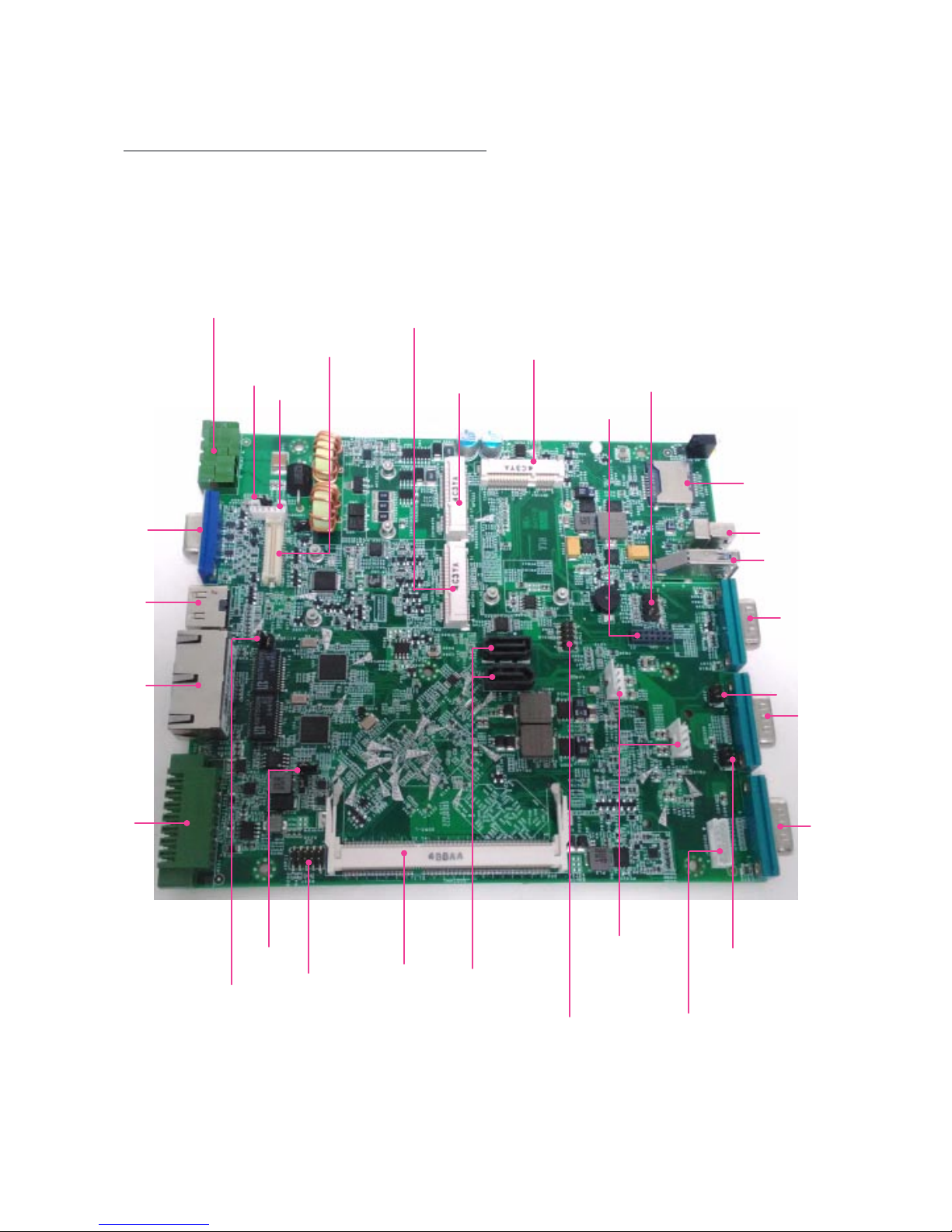
Connectors and Jumpers
The following picture highlights the locations of
connectors and jumpers on the motherboard.
AUDIO1
INVER1
MPCIE1
SATA1/2
JSPI1
JLPC1
SATAPWR1/2
MSATA1
MPCIE2
JVLCD1
PRJK1
JRI1
JCMOS1/2
VGA1
LVDS1
HDMI1
LAN1
MIO1
JCFG2
JDEV1
SIM1
DDR3L
USB1
USB2
CAN1
COM2
COM1
JRI2
CN1
JKBMS1
Chapter 3:
Motherboard Information
 Loading...