

Page 1

Embedded &
Industrial Computing
Hardware Platforms for Embedded and Industrial Computing
LEC-7388S
V1.0
>>
User's Manual
Publication date:2014-05-26
Page 2
About
About
Overview
Icon Descriptions
The icons are used in the manual to serve as an indication
of interest topics or important messages. Below is a
description of these icons:
NOTE: This check mark indicates that
there is a note of interest and is something
that you should pay special attention to
while using the product.
Online Resources
The listed websites are links to the on-line product
information and technical support.
Resource Website
Lanner http://www.lannerinc.com
Product Resources
WARNING: This exclamation point
indicates that there is a caution or
warning and it is something that could
damage your property or product.
http://www.lannerinc.com/
download-center/
Acknowledgement
Intel, Pentium and Celeron are registered trademarks of
Intel Corp.
Microsoft Windows and MS-DOS are registered trademarks
of Microsoft Corp.
All other product names or trademarks are properties of
their respective owners.
Compliances and Certification
CE Certication
This product has passed the CE test for environmental
specifications. Test conditions for passing included the
equipment being operated within an industrial enclosure.
In order to protect the product from being damaged by
ESD (Electrostatic Discharge) and EMI leakage, we strongly
recommend the use of CE-compliant industrial enclosure
products.
FCC Class A Certication
This equipment has been tested and found to comply
with the limits for a Class A digital device, pursuant to Part
15 of the FCC Rules. These limits are designed to provide
reasonable protection against harmful interference when
the equipment is operated in a commercial environment.
This equipment generates, uses and can radiate radio
frequency energy and, if not installed and used in
accordance with the instruction manual, may cause
harmful interference to radio communications. Operation
of this equipment in a residential area is likely to cause
harmful interference in which case the user will be required
to correct the interference at his own expense.
Copyright and Trademarks
This document is copyrighted, © 2014. All rights are
reserved. The original manufacturer reserves the right to
make improvements to the products described in this
manual at any time without notice.
No part of this manual may be reproduced, copied,
translated or transmitted in any form or by any means
without the prior written permission of the original
manufacturer. Information provided in this manual is
intended to be accurate and reliable. However, the original
manufacturer assumes no responsibility for its use, nor for
any infringements upon the rights of third parties that
may result from such use.
Embedded and Industrial Computing
2
Page 3

TTaTTable of Contentsbeable of Contents
Chapter 1: Introduction 4
System Specications . . . . . . . . . . . . . . . . . . . . . . . . . . . . . . . . . . . . . . . . . . . 4
Package Contents . . . . . . . . . . . . . . . . . . . . . . . . . . . . . . . . . . . . . . . . . . . . . 5
Chapter 2: System Components 6
System Drawing . . . . . . . . . . . . . . . . . . . . . . . . . . . . . . . . . . . . . . . . . . . . . . 6
Block Diagram: The MainBoard . . . . . . . . . . . . . . . . . . . . . . . . . . . . . . . . . . . . . 7
Front Connectors. . . . . . . . . . . . . . . . . . . . . . . . . . . . . . . . . . . . . . . . . . . . . . 8
Rear Connectors . . . . . . . . . . . . . . . . . . . . . . . . . . . . . . . . . . . . . . . . . . . . . . 9
Chapter 3: Board Layout 10
Motherboard Layout-Top View . . . . . . . . . . . . . . . . . . . . . . . . . . . . . . . . . . . . .10
Motherboard Layout-Bottom View . . . . . . . . . . . . . . . . . . . . . . . . . . . . . . . . . .11
Docking Board . . . . . . . . . . . . . . . . . . . . . . . . . . . . . . . . . . . . . . . . . . . . . . .12
Connectors and Jumpers List. . . . . . . . . . . . . . . . . . . . . . . . . . . . . . . . . . . . . .13
Jumper Settings . . . . . . . . . . . . . . . . . . . . . . . . . . . . . . . . . . . . . . . . . . . . . .14
Chapter 4: Hardware Setup 17
Preparing the Hardware Installation. . . . . . . . . . . . . . . . . . . . . . . . . . . . . . . . . .17
Installing the System Memory . . . . . . . . . . . . . . . . . . . . . . . . . . . . . . . . . . . . .17
Installing 3G and Wireless Modules . . . . . . . . . . . . . . . . . . . . . . . . . . . . . . . . . .18
Installing a 3G SIM Card . . . . . . . . . . . . . . . . . . . . . . . . . . . . . . . . . . . . . . . . .18
Installing the Hard Disk . . . . . . . . . . . . . . . . . . . . . . . . . . . . . . . . . . . . . . . . . .18
Appendix A: Terms and Conditions 19
Warranty Policy . . . . . . . . . . . . . . . . . . . . . . . . . . . . . . . . . . . . . . . . . . . .19
RMA Service . . . . . . . . . . . . . . . . . . . . . . . . . . . . . . . . . . . . . . . . . . . . . .19
3
Page 4
Chapter 1
Introduction
Chapter 1:
Introduction
Thank you for choosing the LEC-7388S. The LEC-7388S is
an Open Pluggable Specification (OPS) for digital signage
application. The LEC-7388S addresses digital signage
market fragmentation and simplifies device installation,
usage, maintenance, and upgrades.
This LEC-7388S provides a rich I/O capabilities via highbandwidth interfaces such as Mini-PCI Express 2.0 (with
SIM card reader), Serial ATA 3.0, and Hi-Speed USB 3.0
connectivity. With the integrated Intel HD graphics 4600
(on Intel Core i3/i5) and HD graphics (on Intel Celeron
2000E), the system is able to support 4K display and full
HD playback respectively.
The system also features an add-on module connected
via a JAE 80-pin connector, which provides additional
connectivity for another 3 USB ports, one HDMI, one
DisplayPort, and one functional input/output block for
multiple functions including pluggable module power
status, power-on via display panel, pluggable board
detect, consumer electronics control (CEC), and system
fan control.
Other I/O capability includes an Intel® i217 Gigabit
Ethernet. Together, they give a great selection for data
communication in display applications.
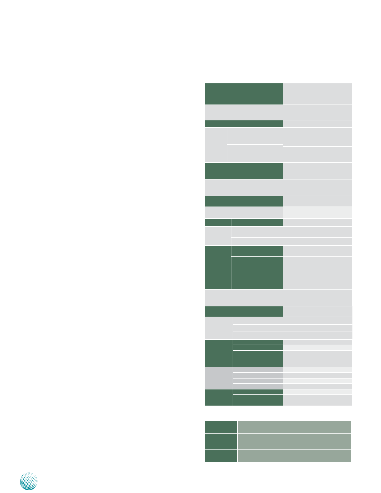
System Specifications
Processor Options
Chipset Intel® QM87
BIOS AMI SPI Flash BIOS
System
Memory
USB
Super I/O
Expansion Bus
OS Support
Storage HDD/SSD Support 1 x 2.5” SSD drive bay
Networking
Display
Functional I/O
LEDs
Physical
Characteristics
Environment
Power
Standard
and Regulation
LEC-7388S-CA
Ordering Information
Socket
Technology
Max. Capacity Up to 16 GB
LAN
Controller Intel i217
Graphics Controller
Display Interface
Housing Heavy Steel
Weight 1.1Kg
Dimensions (WxHxD) 220 x 46 x 172 mm
Operating Temperature -5°C to +45°C
Storage Temperature -20~80°C
Ambient Relative
Humidity
(non-condensing)
Input Voltage +12 V
Power Consumption 38.4 W
Connector DC jack with lock
AC Adapter 60W, 12V/5A with lock
EMC CE/FCC
Green product RoHS
Intel® Core™ i5-4400E
Intel® Core™ i3-4102E
Intel® Celeron 2000E
2 x SODIMM sockets to support up
to 16 GB DDR3L-1333 unbuffered
and non-ECC SDRAM
DDR3L 1333 MHz
2x USB 3.0 TypeA in the front panel
2x USB 2.0 and 1x USB 3.0 through
JAE TX25 80-pin connector
1x LPC Super I/O support Serial port,
GPIO, Watchdog timer and
Hardware monitor
1x mini-PCIexpress socket for minicard module
Microsoft Window 7, Windows 8
Embedded
1 x 10/100/1000 Mbps,
Autosensing,RJ-45
Intel® HD Graphics 4600 or HD
Graphics
2x HDMI, 4096x2304@24Hz/2560x1
600@60Hz(LEC-7388S-5A/3A)
1x DisplayPort output,
3840x2160@60Hz (LEC-7388S-5A/3A)
Terminal block 2x5 pin include
Power_ON, Power_DECT, Power_
Status, UART and FAN power
1x green for power-on status, 1x
green for storage status
5 to 95% (non-condensing)
Embedded and Industrial Computing
LEC-7388S-5A 4K Digital Signage System with Intel® Core™ i5-4400E CPU
LEC-7388S-3A 4K Digital Signage System with Intel® Core™ I3-4102E CPU
LEC-7388S-CA Full-HD Digital Signage System with Intel® Celeron® 2000E
4
Page 5

Chapter 1
Package Contents
Your package contains the following items:
LEC-7388S System •
60W Power Adaptor with lock •
Drivers and User’s Manual CD •
Introduction
Embedded and Industrial Computing
5
Page 6
Chapter 2
Chapter 2:
System Components
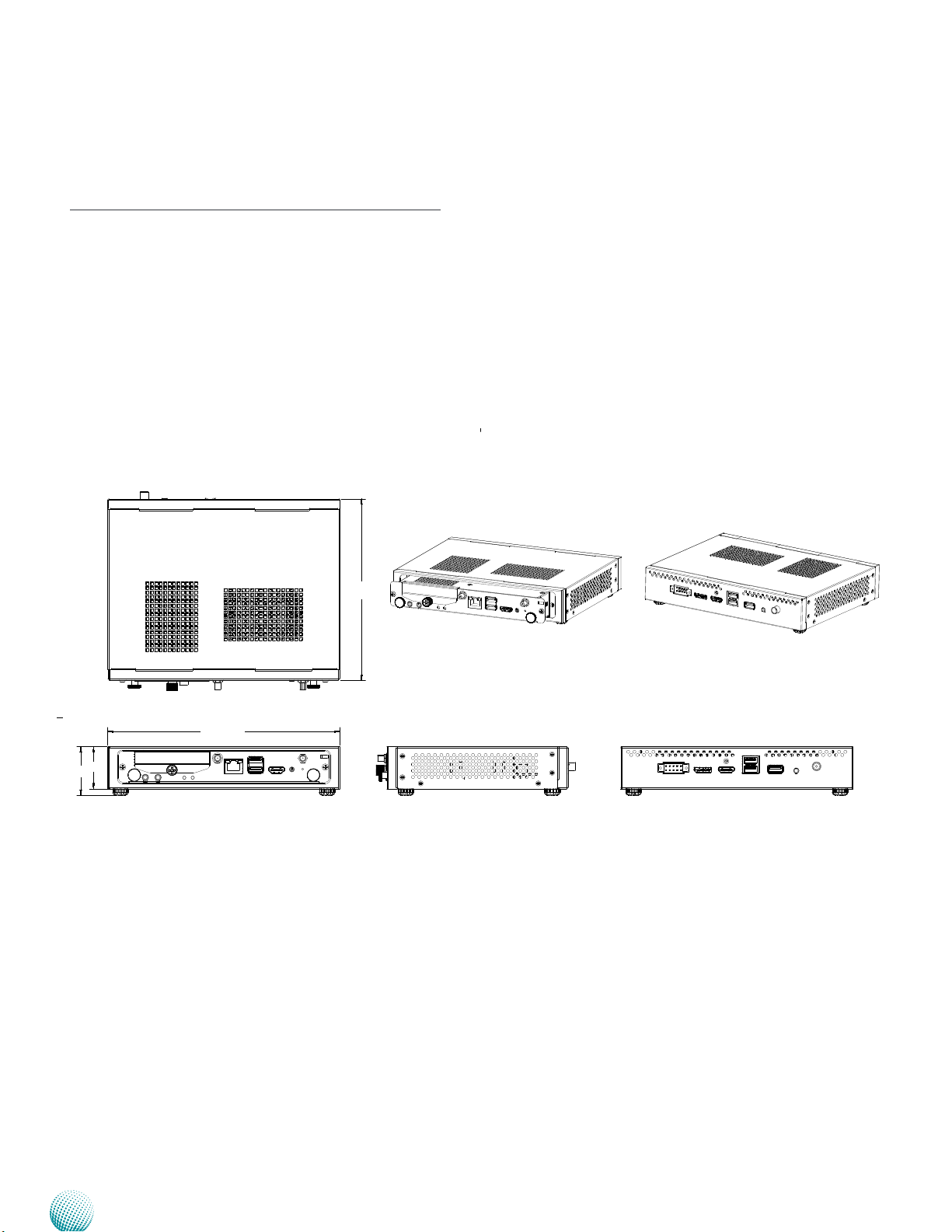
System Drawing
Mechanical dimensions of the LEC-7388S.
Unit: mm
System Information
46
172
220.4
40
Embedded and Industrial Computing
6
Page 7

Chapter 2
Mobile
Intel QM87
Chipset
4th
Generation
Intel Core
I5-4400E
DDR III
SODIMM B
DMI
DDR3
PCIex1
Giga LAN
PHY
IntelR i210
FDI
2 x SO-DIMM
Sockets
(Dual channel)
3 x USB2.0/1 x USB3.0
TMDS
Control Signal (UART)
Super I/O
JAE TX25
80-Pin
Connector
USB
PCIe
Serial
Port
2 x Realtek
ALC886
Codec
Line-In/
MIC
Audio
L/R channel
DC Input
+12
HDMI
Display Port
BIOS
Support
1x SATA
Port
2x Type-A
USB 3.0
External
2.5" Driv
Mini-PCIe
Socket
LED
Power-ON Reset
Intel High Definition Audio
Audio Jack
output
USB 3.0 Port
USB 2.0 Type A
dual port
Display Port
HDMI Port
2 x5 Terminal
Block
Audio Out
USB 3.0
USB 2.0
Display Port
HDMI Signal
RS-232 (TX, RX)
DC-DC
Converter
DC-IN from
Power
Adaptor
DC +12V IN
Block Diagram: The MainBoard
The block diagram depicts the relationships among the
interfaces and modules on the motherboard.
System Information
Intel i217
Embedded and Industrial Computing
7
Page 8

Chapter 2
Front Connectors
System Information
F2
F1
F8
Component Description Pin Definition Reference
F9
F3
F4 F5
F6
F7
F1 Hard Disk Slot External 2.5” hard drive bay for easy access
and replacement of the data storage. It sup-
ports SATA 3.0 specification
F2 Antenna Hole Reserved hole for 3G/Wi-Fi module antenna
F3 Gigabit Ethernet LAN port The LAN port is provided by Intel i217 Ethernet
LAN1 on page 15
controller which supports10/100/1000Mbps
connection speeds and PXE (Preboot
eXecution Environment). The LAN port LED
indicator is described below:
LINK/ACT (Amber)
On/Flashing: The port is linking and •
SPEED
LINK/ACT
active in data transmission.
Off: The port is not linking.•
SPEED (Green/Yellow)
Yellow: The connection speed is •
1000Mbps.
Green: The connection speed is 100Mbps•
Off: .The connection speed is 10Mbps.•
F4 USB 3.0 type A ports Two USB 3.0 type A ports USB1 on page 15
R5 HDMI Port An HDMI port which supports both
HDMI1 on page 14
4096x2304@24Hz (4K display) and
2560x1600@60Hz resolutions.
F6 Power-on Button with
Dual LED
ATX power-on button with LEDs: stand-by
mode in red; power-on mode in green.
F7 Reset Button A hardware reset button
F8 Mic-in Port/Line-out Connect audio devices to these port. MIC1/LINE1 on page 14
F9 HDD (Green) and
Power LED (Green)
HDD
Blinking: data access activities•
Off: no data access activities•
Power
On: The computer is on.•
Off: The computer is off .•
Embedded and Industrial Computing
8
Page 9

Chapter 2
Rear Connectors
System Information
R1
Component Description Pin Definition Reference
R1 Multi-function I/O This multi-functional I/O provides signals for Power-
on, Power Status, Power_DETEC, FAN and TX/RX for
UART communication.
R2 Display Port A DisplayPort which supports 3840x2160@60Hz
resolution
R3 HDMI An HDMI port which supports both 4096x2304@24Hz
(4K display) and 2560x1600@60Hz resolutions.
R4 USB 2.0 Ports Two USB 2.0 ports which provides data transmission
up to 480Mbps.
R5 USB 3.0 Port A USB 3.0 port which provides data transmission up
to 5 Gbit/s.
R6 Audio Port An audio jack output for R/L channels
F7 DC-in Power Jack It requires a power-in DC with 12V. The power
adaptor has a screw-lock type of connector for
secure connection.
R2
R4
R3
R5 R6 R7
CTR1 on page 16
Embedded and Industrial Computing
9
Page 10

Chapter 3
Chapter 3:
Board Layout
Motherboard Layout-Top View
The motherboard layout shows the connectors on the
board. Refer to table 3.1 for pin definitions.
Motherboard Information
SATA1
OPS1
CMOS1
Embedded and Industrial Computing
LAN1
USB1
HDMI1
10
Page 11

Chapter 3
Motherboard Layout-Bottom View
Motherboard Information
MIC1
LINE1
MPCIE1
Embedded and Industrial Computing
SIM1
11
Page 12

Chapter 3
Docking Board
The connectors on the LEK-IOB1 docking board. Refer to
table 3.2 for pin definitions.
PWR1
AUDIO1
USB1
USB2
HDMI1
Motherboard Information
DP1
CTR1
Embedded and Industrial Computing
12
Page 13

Chapter 3
Motherboard Information
Connectors and Jumpers List
The tables below list the function of each of the board
connectors by labels shown above. The next section in
this chapter gives pin definitions.
Table 3.1 Connector List for LEB-7388
Labels Function Pin Denition Reference Page
CMOS1
HDMI1
LAN1
LINE1
MIC1
MPCIE1
OPS Connector
USB1
Clear CMOS Jumper
HDMI Connector
LAN Port
Line-out Phone Jack
Mic-in Phone Jack
Mini-PCIe Connector
JAE TX-25 80-pin Connector
Dual Stack USB type A Connectors
P15
P14
P15
P14
P14
P15
P14
P15
Table 3.2 Connector List for LEK-IOB1
Labels Function Pin Denition Reference Page
CTR1
Multi-function I/O
P16
Embedded and Industrial Computing
13
Page 14

Chapter 3
Motherboard Information
Jumper Settings
LEB-7388
OPS Connector (OPS1) : This plug is for connecting
its slot-in module and it provides the TMDS, DVI-D, DP,
UART and USB2.0 signals.
PIN Signal PIN Signal
1 DDP_3N 41 RSVD
2 DDP_3P 42 RSVD
3 GND 43 RSVD
4 DDP_2N 44 RSVD
5 DDP_2P 45 RSVD
6 GND 46 RSVD
7 DDP_1N 47 RSVD
8 DDP_1P 48 RSVD
9 GND 49 RSVD (DDP_
AUX_EN)
10 DDP_0N 50 SYS_FAN_EN
11 DDP_0P 51 UART_RX
12 GND 52 UART_TX
13 DDP_AUXN 53 GND
14 DDP_AUXP 54 Stda_SSRX15 DDP_HPLUG 55 Stda_SSRX+
16 GND 56 GND
17 TMDS_CLKN 57 Stda_SSTX18 TMDS_CLKP 58 Stda_SSTX+
19 GND 59 GND
20 TMDS0N 60 USB_PN2
21 TMDS0P 61 USB_PP2
22 GND 62 GND
23 TMDS1N 63 USB_PN1
24 TMDS1P 64 USB_PP1
25 GND 65 GND
26 TMDS2N 66 USB_PN0
27 TMDS2P 67 USB_PP0
28 GND 68 GND
29 TMDS_DDC_
DATA
30 TMDS_DDC_
CLK
31 TMDS_HPLUG 71 CEC
32 GND 72 PB_DET
33 DC_IN 73 PS_ON#
34 DC_IN 74 PWR_STATUS
35 DC_IN 75 GND
36 DC_IN 76 GND
37 DC_IN 77 GND
38 DC_IN 78 GND
39 DC_IN 79 GND
40 DC_IN 80 GND
69 AZ_LINEOUT_L
70 AZ_LINEOUT_R
Line-out Jack (Line 1)
PIN Signal
1 LINE_OUT_R
2 N.C
3 LINE_OUT_L
4 EARPHONE DET
5 GND
6 GND
Microphone Jack (MIC1)
PIN Signal
1 MIC_R
2 N.C
3 MIC_L
4 MIC DET
5 GND
6 GND
High-Definition Multimedia Interface (HDMI1)
PIN NO. Signal PIN NO. Signal
1 DATA2+ 2 GND
3 DATA2- 4 DATA1+
5 GND 6 DATA17 DATA0+ 8 GND
9 DATA0- 10 CLK+
11 GND 12 CLK13 N.C 14 N.C
15 DDC CLK 16 DDC DAT
17 GND 18 HDMI_VCC
19 HPD
Embedded and Industrial Computing
14
Page 15

Chapter 3
Motherboard Information
Gigabit Ethernet (LAN1)
Pin No. Signal
Fast Ethernet Gigabit Ethernet
1 TX+ MD0+
2 TX- MD0
3 RX+ MD1+
4 T45 MD2+
5 T45 MD26 RX- MD17 T78 MD3+
8 T78 MD39 10-/100-/1000+
10 10+/100+/100011 Link+/ACT12 Link-/ACT+
Dual Stack USB 3.0 Type A Connector (USB1)
Mini PCI-Express with SIM Card Reader(MPCIE1)
PIN NO. Signal PIN NO. Signal
1 WAKE# 2 +3.3V
3 RSVD 4 GND
5 RSVD 6 +1.5V
GND 13 GND
7 CLKREQ# 8 UIM_PWR
9 GND 10 UIM_DATA
11 REFCLK- 12 UIM_CLK
13 REFCLK+ 14 UIM_RESET
15 GND 16 UIM_VPP
Key
17 RSVD 18 GND
19 RSVD 20 W_DISABLE#
21 GND 22 PERST#
23 PERn0 24 +3.3V
25 PERp0 26 GND
27 GND 28 +1.5V
29 GND 30 SMB_CLK
31 PETn0 32 SMB_DATA
33 PETp0 34 GND
35 GND 36 USB_D+
37 GND 38 USB_D39 +3.3V 40 GND
41 +3.3V 42 LED_WWAN#
43 GND 44 LED_WLAN#
45 RSVD 46 LED_WPAN#
47 RSVD 48 +1.5V
49 RSVD 50 GND
51 RSVD 52 +3.3V
PIN NO. Signal PIN NO. Signal
1 USB_VCC1 10 USB_VCC2
2 USB1_D- 11 USB2_D3 USB1_D+ 12 USB2_D+
4 GND 13 GND
5 USB1_RX- 14 USB2_RX6 USB1_RX+ 15 USB2_RX+
7 GND 16 GND
8 USB1_TX- 17 USB2_TX9 USB1_TX+ 18 USB2_TX+
Clear CMOS Jumper (CMOS1)
PIN No. Signal
3 2 1
1-2 Normal (Default)
2-3 Clear CMOS
Embedded and Industrial Computing
15
Page 16

Chapter 3
LEK-IOB1
Multi-function I/O (CTR1)
PIN NO. Signal PIN NO. Signal
1 Power_ON 2 NC
3 Power_DETEC 4 Power_Status
5 GND 6 GND
7 UART_TXD 8 FAN+
9 UART_RXD 10 GND
Motherboard Information
Embedded and Industrial Computing
16
Page 17

Chapter 4
Hardware Setup
Chapter 4:
Hardware Setup
Preparing the Hardware Installation
To access some components and perform certain service
procedures, you must perform the following procedures
first.
WARNING: To reduce the risk of personal injury,
electric shock, or damage to the equipment,
remove the power cord to remove power from
the server. Portions of the power supply and some
internal circuitry remain active until power is
removed.
Unpower the LEC-7388S and make sure that the power 1.
source is removed.
Disconnect the two screws on the front panel from the 2.
system chassis. Pull the OPS module out for component
removal or installation.
Installing the System Memory
The motherboard supports DDR3L memory that features
data transfer rates of 1333 MHz to meet the higher
bandwidth requirements of the latest operating system
and Internet applications. It comes with one Double Data
Rate 3 Low Voltage (DDR3L) Small Outline Dual Inline
Memory Module (SO-DIMM) socket.
Put the device upside down.1.
Take off the cover to access the memory.2.
Align the memory module’s key with the SO-DIMM 3.
socket’s key.
Install the SO-DIMM.4.
Install the cover back to the system.5.
Embedded and Industrial Computing
Note:
SO-DIMMs installed should meet the required 1.
speed which is DDR3L 1333 MHz. Do not install
SO-DIMM supporting different speeds.
The motherboards can support up to 16 GB 2.
memory capacity in maximum.
17
Page 18

Chapter 4
Hardware Setup
Installing 3G and Wireless Modules
Take off the cover to access the Mini-PCIe and SIM 1.
card.
Align the wireless module’s cutout with the Mini-PCIe 2.
slot notch.
Insert the wireless module into the connector 3.
diagonally.
Push the other end of the wireless module and secure 4.
it in place with the screws.
Install the Antenna to the module.5.
Installing a 3G SIM Card
Take off the cover to access the Mini-PCIe and SIM 1.
card.
Unlock the SIM card tray by sliding it outward and 2.
open it.
Place the SIM card in the tray. Make sure the ICs is in 3.
contact with the socket. The angled corner of the SIM
ensures that the card fits only the correct way in the
tray.
Close and lock the tray. You should feel a click when 4.
the SIM card is locked securely in the socket.
Installing the Hard Disk
The system can accommodate one Serial-ATA 2.5” disk.
Follow these steps to install a hard disk into the LEC7388S):
Take out the hard disk tray from the system.1.
Place hard disk on the hard disk tray and align the holes 1.
of the hard disk with the mounting holes on the tray.
Fix the hard disk on the hard disk tray by using 2 2.
mounting screws
Push the hard disk into the hard disk slot and secure it 3.
with a screw.
Drive Connector
Power Connector
LockUnlock
Note:
The system only accommodates 2.5” SSD. It
supports SATA 3.0 specification.
Embedded and Industrial Computing
18
Page 19

Appendix A
Terms and Conditions
Appendix A:
Terms and Conditions
Warranty Policy
All products are under warranty against defects in 1.
materials and workmanship for a period of one year
from the date of purchase.
The buyer will bear the return freight charges for 2.
goods returned for repair within the warranty period;
whereas the manufacturer will bear the after service
freight charges for goods returned to the user.
The buyer will pay for repair (for replaced components 3.
plus service time) and transportation charges (both
ways) for items after the expiration of the warranty
period.
If the RMA Service Request Form does not meet the 4.
stated requirement as listed on “RMA Service,” RMA
goods will be returned at customer’s expense.
The following conditions are excluded from this 5.
warranty:
RMA Service
Requesting a RMA#
To obtain a RMA number, simply fill out and fax the 1.
“RMA Request Form” to your supplier.
The customer is required to fill out the problem code 2.
as listed. If your problem is not among the codes listed,
please write the symptom description in the remarks
box.
Ship the defective unit(s) on freight prepaid terms. 3.
Use the original packing materials when possible.
Mark the RMA# clearly on the box. 4.
Note: Customer is responsible for shipping
damage(s) resulting from inadequate/loose
packing of the defective unit(s). All RMA# are valid
for 30 days only; RMA goods received after the
effective RMA# period will be rejected.
Improper or inadequate maintenance by the customer
Unauthorized modification, misuse, or reversed
engineering of the product Operation outside of the
environmental specifications for the product.
Embedded and Industrial Computing
19
 Loading...