

Page 1
Operator Manual
LP222cn
LP222cn
LP222cnLP222cn
your document management partner
Printer Operator Guide
Page 2

Introduction
This manual contains detailed instructions and notes on the operation and use of this machine. For your
safety and benefit, read this manual carefully before using the machine. Keep this manual in a handy
place for quick reference.
Power Source
120 V, 60 Hz, 11 A or more
Please be sure to connect the power cable to a power source as above.
Laser Safety:
This machine is considered class I laser device, safe for office/ EDP use. The machine contains 5 milliwatt, 770 - 795 nanometer wavelength, AlGaInp Laser Diode (4 provided). Safety precautions and interlock mechanisms have been designed to prevent any possible laser beam exposure to the operator.
Important
Contents of this manual are subject to change without prior notice. In no event will the company be liable for direct, indirect, special, incidental, or consequential damages as a result of handling or operating the machine.
Caution:
Use of controls or adjustments or performance of procedures other than those specified in this manual
might result in hazardous radiation exposure.
Do not copy or print any item for which reproduction is prohibited by law.
Copying or printing the following items is generally prohibited by local law:
bank notes, revenue stamps, bonds, stock certificates, bank drafts, checks, passports, driver's licenses.
The preceding list is meant as a guide only and is not inclusive. We assume no responsibility for its
completeness or accuracy. If you have any questions concerning the legality of copying or printing certain items, consult with your legal advisor.
Two kinds of size notation are employed in this manual. With this machine refer to the inch version.
For good copy quality, the supplier recommends that you use genuine toner from the supplier.
The supplier shall not be responsible for any damage or expense that might result from the use of parts
other than genuine parts from the supplier with your office products.
Some illustrations in this manual might be slightly different from the machine.
Certain options might not be available in some countries. For details, please contact your local dealer.
Page 3
Safety Information
When using your printer, the following safety precautions should always be followed.
In this manual, the following important symbols are used:
Indicates a potentially hazardous situation which, if instructions are not followed, could result
in death or serious injury.
Indicates a potentially hazardous situation which, if instructions are not followed, may result
in minor or moderate injury or damage to property.
R WARNING:
• Confirm the wall outlet is near the machine and freely accessible, so
that in the event of emergency, it can be unplugged easily.
• Plug and unplug the power cable with dry hands, or an electric shock
could occur.
• Only connect the machine to the power source described in the manual.
• Avoid multi-wiring.
• Do not damage, break or make any modifications to the power cord.
Do not place heavy objects on it, pull it hard or bend it more than necessary. These actions could cause an electric shock or fire.
• Do not incinerate spilled toner or used toner. Toner dust is flammable
and might ignite when exposed to an open flame.
• Disposal should take place at an authorized dealer or an appropriate
collection site.
• If you dispose of the used toner containers yourself, dispose of them
according to local regulations.
• Dispose at an authorized dealer or approved collection site. If you dis-
pose of the used toner containers yourself, do so according to local
regulations.
• Do not risk electric shock by handling the power cord or plug with wet
hands.
• Do not take apart or attempt any modifications to this machine. There
is a risk of fire, electric shock, explosion or loss of sight. If the machine has laser systems, there is a risk of serious eye damage.
• The supplied power cord is for use with this equipment only. Do not
use with other appliances. Doing so may result in fire, electric shock,
or injury.
• Keep the machine away from flammable liquids, gases, and aerosols.
A fire or an electric shock might occur.
Page 4

R CAUTION:
• Place no objects on the right cover.
• Do not pull out the paper tray forcefully. If you do, the tray might fall and
cause an injury.
• The inside of this printer becomes very hot. Do not touch parts labelled “v”
(indicating a hot surface). Touching these parts will result in burns.
• Do not handle the plug with wet hands. Doing so might cause an electrical
shock.
• Keep the machine in an area that is within optimum environmental conditions. Operating the machine in an environment that is outside the recommended ranges of humidity and temperature can cause an electrical fire
hazard. Keep the area around the socket free of dust. Accumulated dust
can become an electrical fire hazard.
• Place the machine on a strong and level surface. Otherwise, it might fall and
injure someone.
• If toner or used toner is inhaled, gargle with plenty of water and move into
a fresh air environment. Consult a doctor if necessary.
• If your skin comes into contact with toner or used toner, wash the affected
area thoroughly with soap and water.
• If toner or used toner gets into your eyes, flush immediately with large
amounts of water. Consult a doctor if necessary.
• If toner or used toner is swallowed, dilute by drinking a large amount of water. Consult a doctor if necessary
• Avoid getting toner on your clothes or skin when removing a paper jam or
replacing toner. If your skin comes into contact with toner, wash the affected
area thoroughly with soap and water.
• If toner gets on your clothing, wash with cold water. Hot water will set the
toner into the fabric and may make removing the stain impossible.
• Keep toner (used or unused) and the toner bottle out of reach of children.
• Grip the plug, not the cord, when pulling the plug from the socket. Pulling
the cord causes wear and tear that can result in fire or electric shock.
• Wait at least one hour after power off before replacing parts. Not allowing
the printer to cool may result in burns.
• Lifting the paper feed unit carelessly or dropping it may cause injury.
Page 5

R CAUTION:
• When removing misfed paper, do not touch the fusing unit because it could
be very hot.
• The printer weights approximately 32 kg (70.5 lb.). When moving the printer, use the inset grips on both sides, and lift slowly. The printer will break or
cause injury if dropped.
• Before installing options, the machine should be turned off and unplugged
for at least half an hour. Components inside the machine become very hot,
and can cause a burn if touched.
• Lifting the paper feed unit carelessly or dropping it may cause an injury.
• Do not touch the inside of the controller board compartment. It may cause
a machine malfunction or a burn.
• When moving the machine, each person should hold the handles that are
located on opposite sides, and then lift it slowly. Lifting it carelessly or dropping it may cause an injury.
• When you move the printer, remember to unplug the power cord from the
wall outlet to avoid a fire or an electric shock.
• When moving the printer after use, do not take out any of the Toners, Photo
Conductor Units, nor the Waste Toner Cartridge to prevent toner spill inside
the machine.
• When lifting the machine, use the inset grips on both sides. Otherwise the
printer could break or cause an injury if dropped.
• Before moving the machine, unplug the power cord from the wall outlet. If
the cord is unplugged abruptly, it could become damaged. Damaged plugs
or cords can cause an electrical or fire hazard.
Note
❒ Under certain temperature and humidity conditions, printing may cause va-
pour to issue from paper. The standard tray (behind the control panel) may
emit steam during printing.
❒ Our products are engineered to meet the highest standards of quality and
functionality. When purchasing expendable supplies, we recommend using
only those specified by an authorized dealer.
Important
❒ Rating voltage of the connector for options: Max. DC 24 V.
❒ Voltage must not fluctuate more than 10%.
Page 6
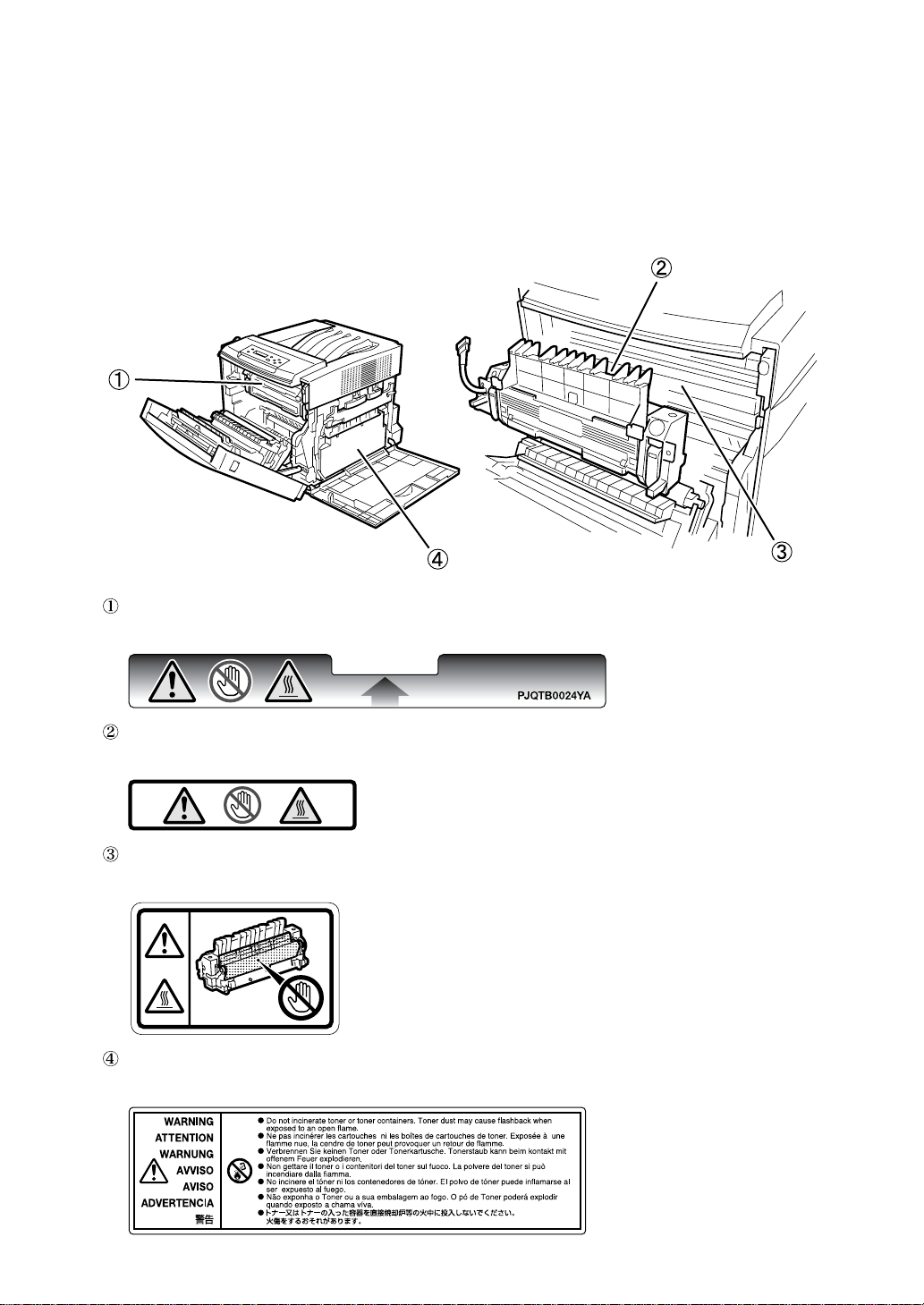
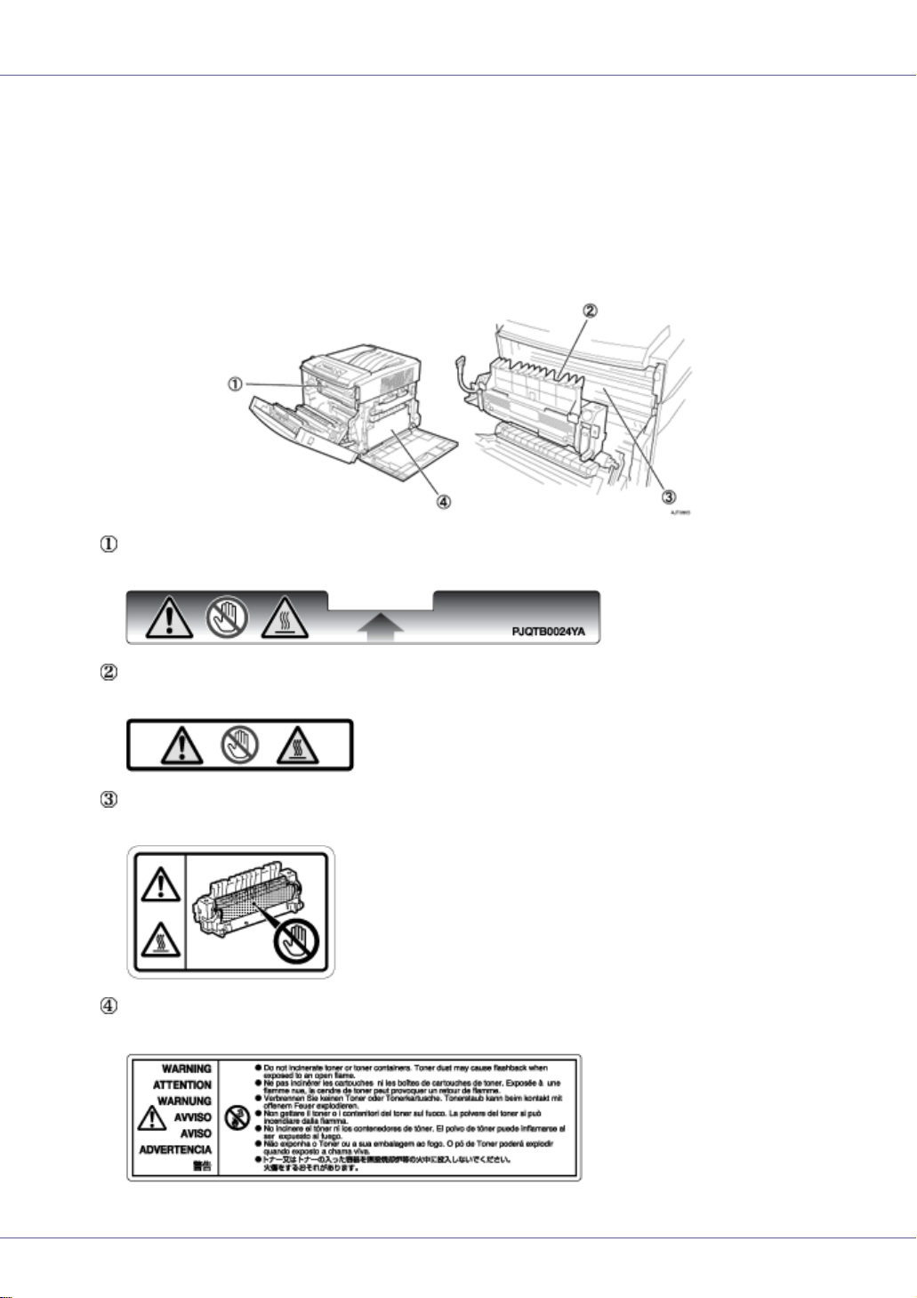
Positions of RWARNING and RCAUTION
labels
This machine has labels for RWARNING and RCAUTION at the positions
shown below. For safety, please follow the instructions and handle the machine
as indicated.
AJT086S
High temperature parts. Turn off the main power and be careful when replac-
ing fusing unit / removing misfed paper.
The inside of this printer becomes very hot. Do not touch parts labelled “v”
(indicating a hot surface). Touching these parts will result in burns.
The inside of this printer becomes very hot. Do not touch parts labelled “v”
(indicating a hot surface). Touching these parts will result in burns.
Do not incinerate toner or toner containers. Toner dust may cause flashback
when exposed to an open flame.
Page 7

In accordance with IEC 60417, this machine uses the following symbols for the main power switch:
a means POWER ON.
b means POWER OFF.
Note to users in the United States of America
Note:
This equipment has been tested and found to comply with the limits for a Class B digital device, pursuant to Part 15 of the FCC Rules. These limits are designed to provide reasonable protection against
harmful interference in a residential installation. This equipment generates, uses and can radiate radio
frequency energy and, if not installed and used in accordance with the instructions, may cause harmful
interference to radio communications. However, there is no guarantee that interference will not occur
in a particular installation. If this equipment does cause harmful interference to radio or television reception, which can be determined by turning the equipment off and on, the user is encouraged to try to
correct the interference by one more of the following measures:
Reorient or relocate the receiving antenna.
Increase the separation between the equipment and receiver.
Connect the equipment into an outlet on a circuit different from that to which the receiver is
connected.
Consult the dealer or an experienced radio /TV technician for help.
Caution:
Changes or modifications not expressly approved by the party responsible for compliance could void
the user's authority to operate the equipment.
Caution (in case of 100BaseTX environment):
Properly shielded cables must be used for connections to host computer (and/or peripheral) in order to
meet FCC emission limits.
Network interface cable with ferrite core must be used for RF interference suppression.
Declaration of Conformity
Product Name: Laser Printer
Model Number: Aficio CL3500N/C7521n/CLP22/LP222cn
Responsible party: Ricoh Corporation
Address: 5 Dedrick Place, West Caldwell, NJ 07006
Telephone number: 973-882-2000
This device complies with Part 15 of the FCC Rules.
Operation is subject to the following two conditions:
1. This device may not cause harmful interference, and
2. this device must accept any interference received,
including interference that may cause undesired operation.
Properly shielded cables must be used for connections to host computer (and/or peripheral)
in order to meet FCC emission limits.
Network interface cable with ferrite core must be used for RF interference suppression.
Pour empêcher que cet appareil cause du brouillage au service faisant l'objet d'une licence,
il doit être utilisé à l'intérieur et devrait être placé loin des fenêtres afin de fournir un écran
de blindage maximal. Si le matériel (ou son antenne d'émission) est installé à l'extérieur, il
doit faire l'objet d'une licence.
Page 8

Note to users in Canada
Note:
This Class B digital apparatus complies with Canadian ICES- 003.
IEEE 802.11b Interface Unit Type H (R-WL11B):
This device complies with RSS 210 of Industry Canada.
To prevent radio interference to the licensed service, this device must be operated indoors only and
should be kept away from windows to provide maximum shielding.
Remarque concernant les utilisateurs au Canada
Avertissement:
Cet appareil numérique de la classe B est conforme à la norme NMB-003 du Canada.
IEEE 802.11b Interface Unit Type H (R-WL11B):
Pour empêcher que cet appareil cause du brouillage au service faisant l'objet d'une licence, il doit être
utilisé à l'intérieur et devrait être placé loin des fenêtres afin de fournir un écran de blindage maximal.
Si le matériel (ou son antenne d'émission) est installé à l'extérieur, il doit faire l'objet d'une licence.
Caution: Lithium Batteries (RTC Back-up):
The danger of explosion exists if a battery of this type is incorrectly replaced. Replace only with the
same or an equivalent type recommended by the manufacturer. Discard used batteries in accordance
with the manufacturer's instructions.
Copyright © 2005
EN USA G139-8513
Page 9

Note to Administrator
This manual is intended to provide administrators with additional information
about the security functions of this printer. Read this manual as well as Setup
Guide and Software Guide.
This manual and its contents should be kept by, and restricted to, administrators.
Password
When you log into this printer, you will be prompted to enter the user name and
password for your account. We strongly recommend you change the factory default user name and create a password immediately to prevent information leakage and unauthorized operations by others.
You will be prompted to enter your login password when performing the following operations:
• Logging in to Administrator mode in Web Image Monitor
• Starting User Management Tool of SmartDeviceMonitor for Admin
• Connecting to the printer via telnet
• Connecting to the printer via ftp
To use the default account, enter “admin” as the user name, and leave the password blank.
You can set the password in Web Image Monitor or telnet.
The password set here can be used to log in for any operation.
Reference
For details about setting a password, see “Monitoring and Configuring the
Printer”, Software Guide, or Web Image Monitor Help.
Addendum for {Menu} function
Administrator menu
The control panel allows you to perform various basic configurations and adjustments that are required to use the printer. However, in order to protect the
printer from threats such as unauthorized access, data manipulation, and tampering, “administrator menus”, which are not normally displayed, are provided
for administrators.
1
Page 10
This printer comes with the following administrator menus:
❖ Administrator menus under [Maintenance]:
• Menu Protect
• List Print Lock
• File Locking
•Unlock Files
Note
❒ The ”File Locking” and “Unlock Files” menus are displayed when the op-
tional hard disk is installed.
❖ Administrator menus under [Host Interface]:
• USB Setting
•Bluetooth
Note
❒[Bluetooth] is displayed when the optional Bluetooth interface unit is installed.
Displaying administrator menus
You can display the administrator menus by using specific key combinations on
the control panel of the printer.
This section describes how to display the administrator menus.
A Check the printer is online.
B Press the {# Enter} key, press the {Escape} key, and then press the {Menu} key.
AGY501S
The menu screen appears.
Menu:
Paper Input
C
Press the
Menu:
Maintenance
2
{U}
or
{T}
key to display [Maintenance], and then press the {# Enter} key.
Page 11

D Press the {U} or {T} key to check the administrator menus including [Menu
Protect] and [List Print Lock] are displayed.
You can now display the administrator menus and make any necessary
changes to the settings.
E Press the {Online} key after completing all the required settings.
The initial screen appears, preventing you from displaying the administrator
menus. To display the administrator menus again, repeat the procedures
from the start.
Maintenance menu parameters (administrator menu)
❖ Menu Protect
You can protect menu settings from accidental changes.
• Level 1
You can preserve settings for the [Maintenance], [System], [Host Interface],
[PCL Menu], [PS Menu], [PDF Menu], and [Language] menus.
• Level 2
You can preserve settings for the [Paper Input], [Maintenance], [System], [Host
Interface], [PCL Menu], [PS Menu], [PDF Menu], and [Language] menus.
•Off
Operation of menu items is unrestricted.
Note
❒ Default: Off
❖ List Print Lock
You can restrict the list and test printing
•On
Specifying [On] normally hides the [List/Test Print] menu, preventing users
from performing any test print operations using the control panel.
•Off
No menu item operations are restricted.
Note
❒ Default: Off
❖ File Locking
If the user tries to access a file and enters the wrong password 10 times, the
file is automatically locked.
•On
•Off
Note
❒ Default: Off
3
Page 12

❖ Unlock Files
You can unlock a file that was locked due to a user entering a wrong password 10 times.
Host Interface menu parameters (administrator menu)
❖ USB Setting
You can specify the USB communication speed.
• Full Speed
You can set the communication speed of USB to USB1.1.
•Auto
Note
❒ Default: Auto
❖ Bluetooth
You can set the operating mode of Bluetooth.
• Public
•Private
Note
❒ Default: Public
❒ This menu item is displayed if the optional Bluetooth interface unit is in-
stalled.
❒ If the settings are changed to “Private” after registering computers that use
this printer with the operating mode set to “PublicPrivate”, only registered
computers can use this printer via the Bluetooth interface unit.
❒ You can change the operating mode in Web Image Monitor or telnet.
Reference
For details about Web Image Monitor, see “Using Web Image Monitor”,
Software Guide. For details about settings, see Web Image Monitor Help.
For details about how to change the operating mode in telnet, see “Remote
Maintenance by telnet”, Software Guide.
Copyright © 2005
4
EN USA G139-8512
Page 13

Setup Guide
Read This First
Trademarks.............................................................................................................3
Safety Information .................................................................................................4
Positions of RWARNING and RCAUTION labels ..............................................8
ENERGY STAR Program .......................................................................................9
How to Read This Manual ...................................................................................10
Guide to the Printer
Exterior: Front View.............................................................................................11
Exterior: Rear View ..............................................................................................12
Inside.....................................................................................................................14
Control Panel........................................................................................................15
Setting Up
Where to Put the Printer......................................................................................17
Checking the Contents of the Box .....................................................................20
Unpacking.............................................................................................................22
Installing the Waste Toner Bottle and Photo Conductor Unit .........................23
Installing the Toner Cartridge.............................................................................29
Loading Paper......................................................................................................33
Turning the Power On .........................................................................................36
Selecting the Display Language.........................................................................38
Test Printing .........................................................................................................40
G1398502_1.00 EN USA G139-8502 Copyright © 2005 1
Page 14

Adjusting the Image Density...............................................................................42
Installing Options
Available Options.................................................................................................44
Option Installation Flow Chart ..................................................................................44
Installing Options......................................................................................................45
Attaching Paper Feed Unit Type 3000................................................................47
Attaching AD440 (Duplex Unit)...........................................................................52
Attaching Memory Unit Type D 128MB, Memory Unit Type E 256MB (SDRAM
Module) ...............................................................................................................55
Attaching Printer Hard Disk Type 3000..............................................................60
Formatting the Printer Hard Disk..............................................................................64
Attaching User Account Enhance Unit Type E .................................................66
Attaching IEEE 1394 Interface Board Type B....................................................70
Attaching IEEE 802.11b Interface Unit Type H ..................................................73
Attaching Bluetooth Interface Unit Type 3245 ..................................................77
Attaching IEEE 1284 Interface Board Type A....................................................81
Attaching Network Data Protection Unit Type C...............................................83
Connecting the Printer
Network Connection ............................................................................................85
USB Connection...................................................................................................87
Parallel Connection .............................................................................................88
IEEE 1394 Connection.........................................................................................89
Configuration
Ethernet Configuration........................................................................................90
IEEE 802.11b (Wireless LAN) Configuration .....................................................95
IEEE 1394 Configuration ...................................................................................101
IP over 1394...........................................................................................................101
SCSI print...............................................................................................................103
Installing the Printer Driver
Quick Install........................................................................................................105
Install the Operating Instructions.....................................................................107
2
Page 15

Read This First
Trademarks
Microsoft, Windows and Windows NT are registered trademarks of Microsoft
Corporation in the United States and/or other countries.
IPS-PRINT Printer Language Emulation Copyright© 1999-2000 Oak Technology, Inc., All rights reserved.
Bluetooth
Other product names used herein are for identification purposes only and might
be trademarks of their respective companies. We disclaim any and all rights to
those marks.
The proper names of the Windows operating systems are as follows:
•Microsoft
•Microsoft
•Microsoft
• The product names of Windows
Microsoft
Microsoft
Microsoft
• The product names of Windows
Microsoft
Microsoft
• The product names of Windows Server
Microsoft
Microsoft
Microsoft
• The product names of Windows NT
Microsoft
Microsoft
®
is a registered trademark of the Bluetooth SIG, Inc. worldwide.
®
Windows® 95 operating system
®
Windows® 98 operating system
®
Windows® Millennium Edition (Windows Me)
®
®
Windows® 2000 Advanced Server
®
Windows® 2000 Server
®
Windows® 2000 Professional
®
Windows® XP Professional
®
Windows® XP Home Edition
®
Windows ServerTM 2003 Standard Edition
®
Windows ServerTM 2003 Enterprise Edition
®
Windows ServerTM 2003 Web Edition
®
Windows NT® Server 4.0
®
Windows NT® Workstation 4.0
2000 are as follows:
®
XP are as follows:
TM
2003 are as follows:
®
4.0 are as follows:
G1398502_1.00 Copyright © 2005 3
Page 16
Read This First
Safety Information
When using your printer, the following safety precautions should always be followed.
In this manual, the following important symbols are used:
Indicates a potentially hazardous situation which, if instructions are not followed, could result in
death or serious injury.
Indicates a potentially hazardous situation which, if instructions are not followed, may result in
minor or moderate injury or damage to property.
4
Page 17

Read This First
• Confirm the wall outlet is near the machine and freely accessible, so
that in the event of emergency, it can be unplugged easily.
• Plug and unplug the power cable with dry hands, or an electric shock
could occur.
• Only connect the machine to the power source described in the man-
ual.
• Avoid multi-wiring.
• Do not damage, break or make any modifications to the power cord.
Do not place heavy objects on it, pull it hard or bend it more than necessary. These actions could cause an electric shock or fire.
• Do not incinerate spilled toner or used toner. Toner dust is flammable
and might ignite when exposed to an open flame.
• Disposal should take place at an authorized dealer or an appropriate
collection site.
• If you dispose of the used toner containers yourself, dispose of them
according to local regulations.
• Dispose at an authorized dealer or approved collection site. If you dis-
pose of the used toner containers yourself, do so according to local
regulations.
• Do not risk electric shock by handling the power cord or plug with wet
hands.
• Do not take apart or attempt any modifications to this machine. There
is a risk of fire, electric shock, explosion or loss of sight. If the machine has laser systems, there is a risk of serious eye damage.
• The supplied power cord is for use with this equipment only. Do not
use with other appliances. Doing so may result in fire, electric shock,
or injury.
• Keep the machine away from flammable liquids, gases, and aerosols.
A fire or an electric shock might occur.
5
Page 18
Read This First
• Place no objects on the right cover.
• Do not pull out the paper tray forcefully. If you do, the tray might fall and
cause an injury.
• The inside of this printer becomes very hot. Do not touch parts labelled “v”
(indicating a hot surface). Touching these parts will result in burns.
• Do not handle the plug with wet hands. Doing so might cause an electrical
shock.
• Keep the machine in an area that is within optimum environmental conditions. Operating the machine in an environment that is outside the recommended ranges of humidity and temperature can cause an electrical fire
hazard. Keep the area around the socket free of dust. Accumulated dust
can become an electrical fire hazard.
• Place the machine on a strong and level surface. Otherwise, it might fall and
injure someone.
• If toner or used toner is inhaled, gargle with plenty of water and move into
a fresh air environment. Consult a doctor if necessary.
• If your skin comes into contact with toner or used toner, wash the affected
area thoroughly with soap and water.
• If toner or used toner gets into your eyes, flush immediately with large
amounts of water. Consult a doctor if necessary.
• If toner or used toner is swallowed, dilute by drinking a large amount of water. Consult a doctor if necessary
• Avoid getting toner on your clothes or skin when removing a paper jam or
replacing toner. If your skin comes into contact with toner, wash the affected
area thoroughly with soap and water.
• If toner gets on your clothing, wash with cold water. Hot water will set the
toner into the fabric and may make removing the stain impossible.
• Keep toner (used or unused) and the toner bottle out of reach of children.
• Grip the plug, not the cord, when pulling the plug from the socket. Pulling
the cord causes wear and tear that can result in fire or electric shock.
• Wait at least one hour after power off before replacing parts. Not allowing
the printer to cool may result in burns.
• Lifting the paper feed unit carelessly or dropping it may cause injury.
6
Page 19
Read This First
• When removing misfed paper, do not touch the fusing unit because it could
be very hot.
• The printer weights approximately 32 kg (70.5 lb.). When moving the printer, use the inset grips on both sides, and lift slowly. The printer will break or
cause injury if dropped.
• Before installing options, the machine should be turned off and unplugged
for at least half an hour. Components inside the machine become very hot,
and can cause a burn if touched.
• Lifting the paper feed unit carelessly or dropping it may cause an injury.
• Do not touch the inside of the controller board compartment. It may cause
a machine malfunction or a burn.
• When moving the machine, each person should hold the handles that are
located on opposite sides, and then lift it slowly. Lifting it carelessly or dropping it may cause an injury.
• When you move the printer, remember to unplug the power cord from the
wall outlet to avoid a fire or an electric shock.
• When moving the printer after use, do not take out any of the Toners, Photo
Conductor Units, nor the Waste Toner Cartridge to prevent toner spill inside
the machine.
• When lifting the machine, use the inset grips on both sides. Otherwise the
printer could break or cause an injury if dropped.
• Before moving the machine, unplug the power cord from the wall outlet. If
the cord is unplugged abruptly, it could become damaged. Damaged plugs
or cords can cause an electrical or fire hazard.
❒ Under certain temperature and humidity conditions, printing may cause va-
pour to issue from paper. The standard tray (behind the control panel) may
emit steam during printing.
❒ Our products are engineered to meet the highest standards of quality and
functionality. When purchasing expendable supplies, we recommend using
only those specified by an authorized dealer.
❒ Rating voltage of the connector for options: Max. DC 24 V.
❒ Voltage must not fluctuate more than 10%.
7
Page 20
Read This First
Positions of RWARNING and RCAUTION
labels
This machine has labels for RWARNING and RCAUTION at the positions
shown below. For safety, please follow the instructions and handle the machine
as indicated.
High temperature parts. Turn off the main power and be careful when replac-
ing fusing unit / removing misfed paper.
The inside of this printer becomes very hot. Do not touch parts labelled “v”
(indicating a hot surface). Touching these parts will result in burns.
The inside of this printer becomes very hot. Do not touch parts labelled “v”
(indicating a hot surface). Touching these parts will result in burns.
Do not incinerate toner or toner containers. Toner dust may cause flashback
when exposed to an open flame.
8
Page 21
Read This First
ENERGY STAR Program
As an ENERGY STAR Partner, we have determined that this machine model meets the ENERGY STAR Guidelines for energy efficiency.
The ENERGY STAR Guidelines intend to establish an international energy-saving system for
developing and introducing energy-efficient office equipment to deal with environmental issues,
such as global warming.
When a product meets the ENERGY STAR Guidelines for energy efficiency, the Partner shall
place the ENERGY STAR logo onto the machine model.
This product was designed to reduce the environmental impact associated with office equipment by means of energy-saving features, such as Low-power mode.
❖ Low-power Mode (Energy Saver mode)
This printer automatically lowers its power consumption 1 minutes after the
last operation has been completed. To exit Low-power (Energy Saver) mode,
press any key on the control panel. For more information about how to configure Energy Saver mode, see “Making Printer Settings with Control Panel”,
Software Guide as a HTML file on the CD-ROM.
❖ Specifications
Energy Saver mode Power Consumption 9 W or less
Default Time 1 minutes
Recovery Time 3 seconds or less
9
Page 22

Read This First
How to Read This Manual
The following set of symbols is used in this manual.
This symbol indicates a potentially hazardous situation that might result in death
or serious injury when you misuse the machine without following the instructions
under this symbol. Be sure to read the instructions, all of which are described in
the Safety Information section.
This symbol indicates a potentially hazardous situation that might result in minor
or moderate injury or property damage that does not involve personal injury
when you misuse the machine without following the instructions under this symbol. Be sure to read the instructions, all of which are described in the Safety Information section.
* The statements above are notes for your safety.
If this instruction is not followed, paper might be misfed, originals might be damaged, or data might be lost. Be sure to read this.
This symbol indicates information or preparations required prior to operating.
This symbol indicates precautions for operation, or actions to take after abnormal
operation.
This symbol indicates numerical limits, functions that cannot be used together,
or conditions in which a particular function cannot be used.
This symbol indicates a reference.
[ ]
Keys that appear on the machine's display.
Keys and buttons that appear on the computer's display.
{ }
Keys built into the machine's control panel.
Keys on the computer's keyboard.
10
Page 23
Guide to the Printer
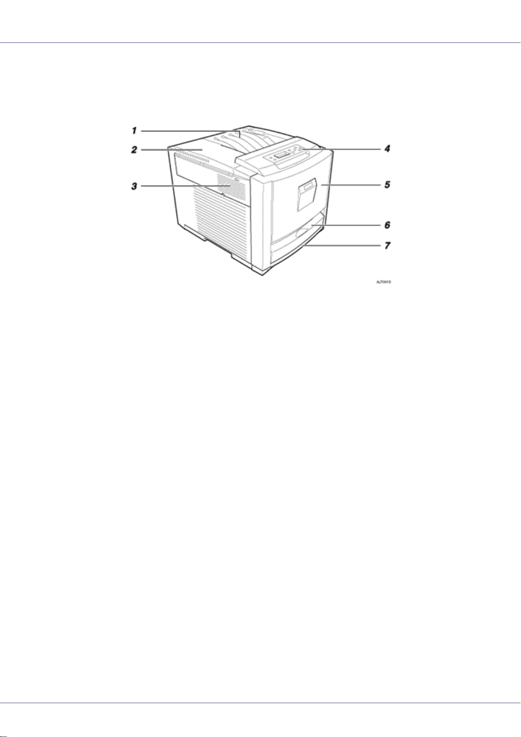
Exterior: Front View
1. Standard Tray
Output is stacked here print side down.
2. Upper Left Cover
Open this to replace toner cartridges.
3. Ventilator
The ventilator helps keep internal components from overheating. Overheating results in
malfunction. Make sure the ventilator is not blocked by objects or in any way obstructed.
4. Control Panel
Contains keys for printer control and a panel display that displays the printer's status.
5. Front Cover
Open this to replace the fusing unit or transfer roller, install the duplex unit, or remove
misfed paper.
6. Bypass Tray
Use this to print onto thick paper, OHP transparencies, custom size paper, and envelopes, as well as plain paper. Special printer driver settings must be made in order to
print onto custom size paper.
7. Tray 1
Up to 530 sheets of plain paper can be loaded here.
G1398502_1.00 Copyright © 2005 11
Page 24
Guide to the Printer
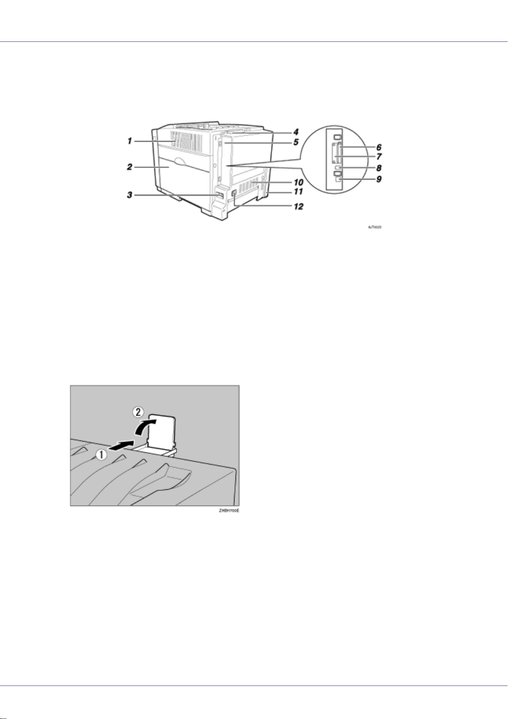
Exterior: Rear View
1. Ventilator
The ventilator helps keep internal components from overheating. Overheating results in
malfunction. Make sure the ventilator is not blocked by objects or in any way obstructed.
2. Right Cover
Open this to replace photo conductor units, the transfer belt , or the waste toner bottle.
3. Power Switch
Use this to turn the power on and off.
4. Standard Tray Extension
Pull this out when printing on paper that is longer than A4 or 8 1/2” × 11”.
5. Controller Board
Slide this out to install options such as the memory unit, user account enhance unit, or
printer hard disk. Plug cables such as the USB cable and Ethernet cable into their connectors here.
6. Expansion Card Slots
Install expansion cards in these slots. There are two slots.
To install an expansion card, use the under slot.
7. Optional Interface Board Slots
Insert an optional 1394 interface board, 802.11b interface unit, wireless interface board,
or 1284 interface board in this slot. Up to one interface board can be inserted at a time.
12
Page 25

Guide to the Printer
8. USB Port
Use a USB cable to connect the printer to a host computer.
9. Ethernet Port
Use a network interface cable to connect the printer to a network.
10. Ventilator
The ventilator helps keep internal components from overheating. Overheating results in
malfunction. Make sure the ventilator is not blocked by objects or in any way obstructed.
11. Optional Paper Feed Unit Connector
Use this to connect the printer to the paper feed unit.
12. Power Port
Connect the power cable to this socket and the other end of the cable directly to the wall
outlet (do not use an extension).
13
Page 26
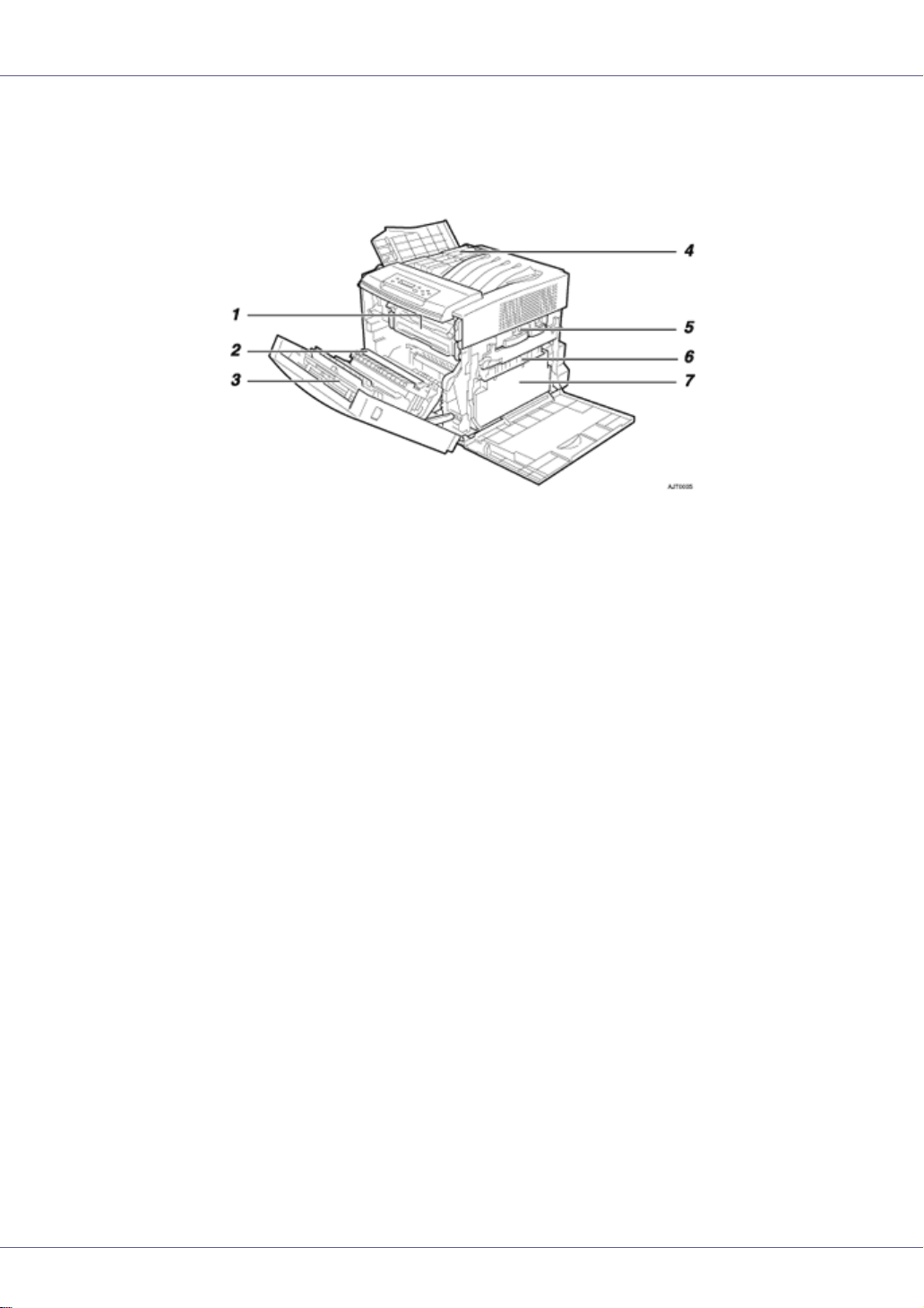
Guide to the Printer
Inside
1. Fusing Unit
Fuses the image onto paper.
When the “Replace Fusing Unit” message appears on the display, replace this unit.
2. Transfer Roller
When the “Replace Fusing Unit” message appears on the display, replace this roller.
3. Duplex Unit (optional for Basic Model Printer)
Use to print on both sides of paper.
4. Toner Cartridges
When the “Add Toner (color)” message appears on the display, replace the toner cartridge of the indicated color.
5. Photo Conductor Unit Color/Black
When the “Replace Color PCU” or “Replace Black PCU” message appears on the display, replace the indicated Photo Conductor Unit.
6. Transfer Belt
When the “Replace Transfer Belt” message appears on the display, replace this unit.
7. Waste Toner Bottle
Collects waste toner. When the “Replace Used Toner Bottle” message appears on the
display, replace this bottle.
14
Page 27
Guide to the Printer
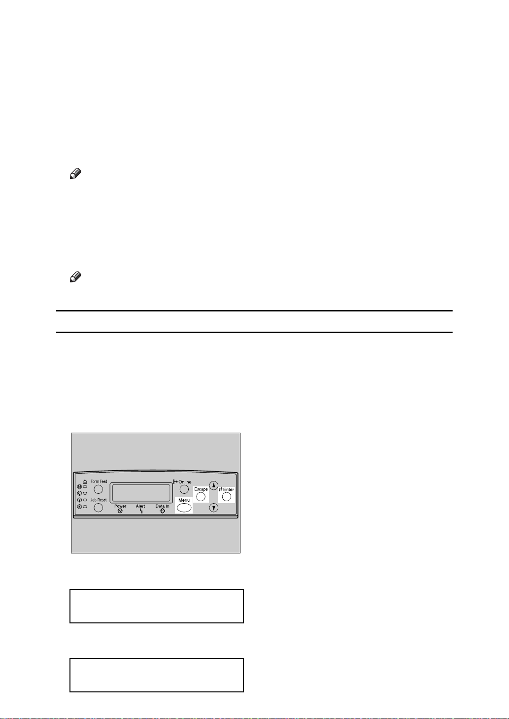
Control Panel
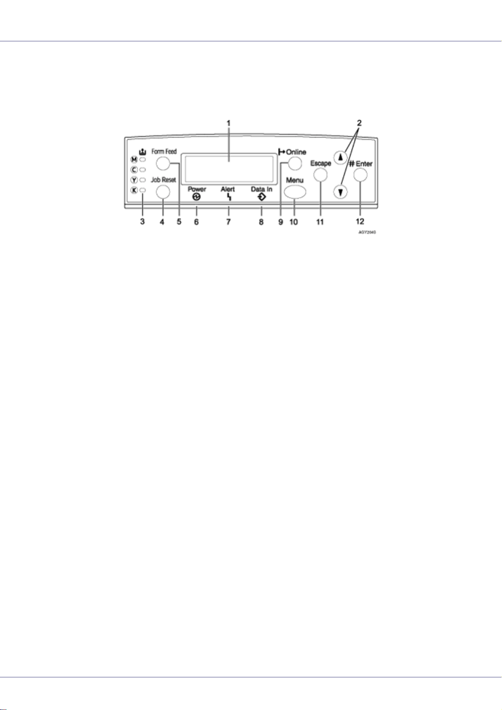
1. Display
Displays current printer status and error messages.
For details about error messages, see Maintenance Guide.
2. {U} {T} keys
Use these keys to increase or decrease values on the display when making settings.
Keep the key pressed to quicken scrolling, and increase or decrease values on the dis-
play in units of 10.
3. Toner End LED
The color of the lit LED indicates toner status for each color.
A yellow light indicates the toner amount is approaching exhaustion. A red light indicates
the toner cartridge needs to be replaced.
4. {Job Reset} key
When the printer is online, press this key to cancel an ongoing print job.
5. {Form Feed} key
When the printer is offline, press this to print all data left in the printer's input buffer.
You can use this to force the printer to print data received in the online status when the
paper size or type does not match the actually set size or type.
6. Power indicator
This indicator remains lit while the power is on. It is unlit when the power is off or while
the printer is in Energy Saver mode.
7. Alert indicator
Lights up whenever a printer error occurs. A red light indicates an error has occurred that
makes printing impossible; the yellow light indicates a potential error during printing.
If the red light is on, follow the instructions that appear on the display.
8. Data In indicator
Blinks when the printer is receiving data from a computer. The Data In indicator is lit if
there is data to be printed.
15
Page 28

Guide to the Printer
9. {Online} key
Indicates whether the printer is online or offline. Press this to switch between online and
offline.
When the lamp is lit, the printer is online, enabling data reception from the host computer.
When the lamp is unlit, the printer is offline, disabling data reception from the host computer.
Press to return to the ready condition.
10. {Menu} key
Press this key to make and check the current printer settings.
For details, See “Making Printer Settings Using the Control Panel”, Software Guide.
11. {Escape} key
Press this key to return to the previous condition on the display.
12. {# Enter} key
Press this key to execute menu items selected on the display.
16
Page 29
Setting Up
Where to Put the Printer
The printer's location should be carefully chosen because environmental conditions greatly affect its performance.
• Confirm the wall outlet is near the machine and freely accessible, so
that in the event of emergency, it can be unplugged easily.
• Only connect the machine to the power source described in the manual.
• Avoid multi-wiring.
• Do not damage, break or make any modifications to the power cord.
Do not place heavy objects on it, pull it hard or bend it more than necessary. These actions could cause an electric shock or fire.
• The supplied power cord is for use with this equipment only. Do not
use with other appliances. Doing so may result in fire, electric shock,
or injury.
• Do not handle the plug with wet hands. Doing so might cause an electrical
shock.
• Keep the machine in an area that is within optimum environmental conditions. Operating the machine in an environment that is outside the recommended ranges of humidity and temperature can cause an electrical fire
hazard. Keep the area around the socket free of dust. Accumulated dust
can become an electrical fire hazard.
• Place the machine on a strong and level surface. Otherwise, it might fall and
injure someone.
• If you use the machine in a confined space, ensure there is continuous air
circulation.
G1398502_1.00 Copyright © 2005 17
Page 30
Setting Up
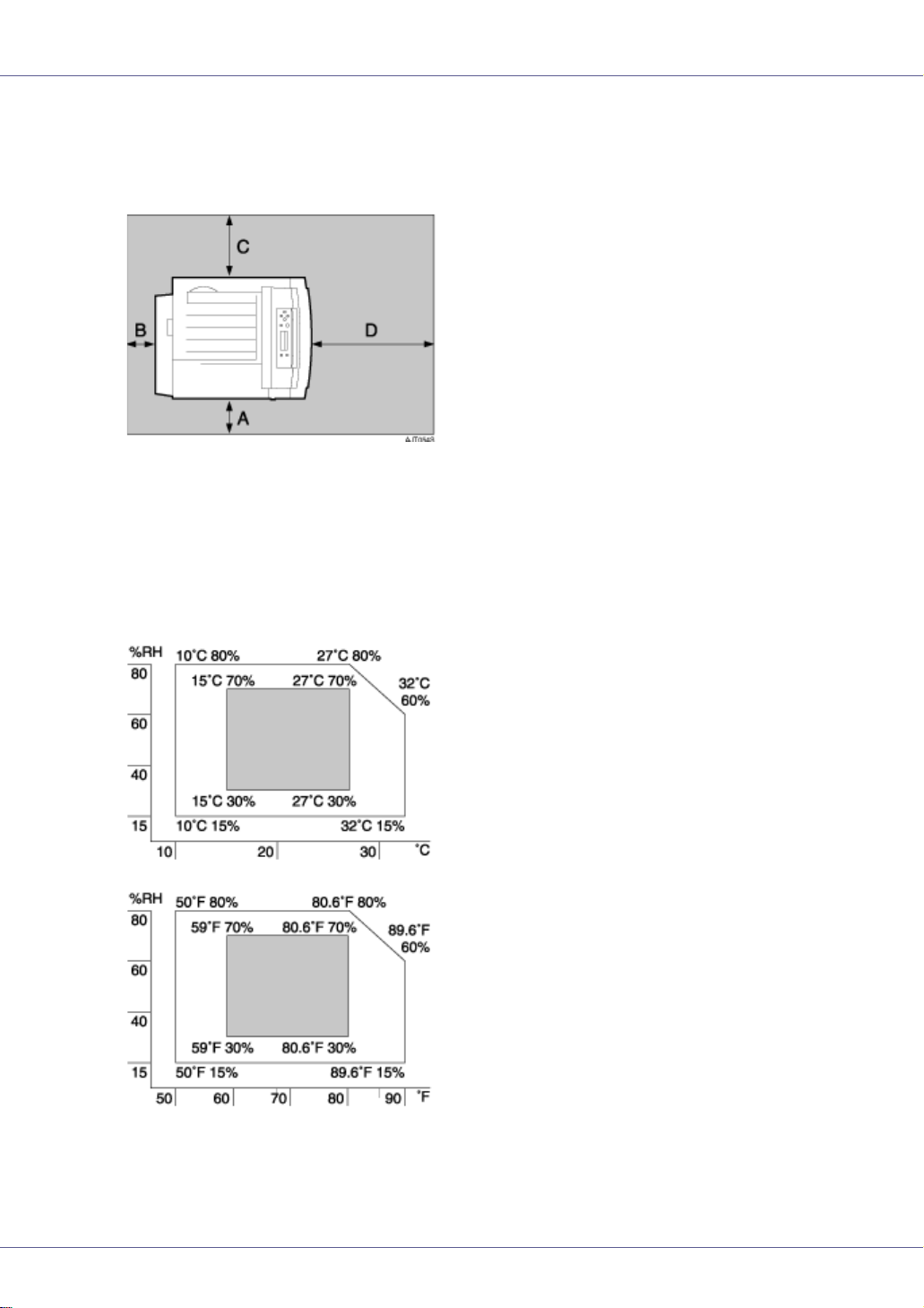
❖ Space Required for Installation
Leave enough space around the printer. This space is necessary to operate
the printer. The recommended (or minimum) space requirements are as follows:
A: 13 cm (5.2 inches) or more
B: 11 cm (4.4 inches) or more
C: 35 cm (14.0 inches) or more
D: 61 cm (24.4 inches) or more
❖ Optimum Environmental Conditions
Permissible and recommended temperature and humidity ranges are as follows:
• White area: Permissible Range
• Gray area: Recommended Range
18
Page 31

Setting Up
❒ The machine must be level within 5 mm, 0.2” from both front to rear and left
to right.
❒ To avoid possible build-up of ozone, locate this machine in a large well ven-
tilated room that has an air turnover of more than 30 m
3
/hr/person.
❒ When you use this machine for a long time in a confined space without
good ventilation, you may detect an odd smell. To keep the workplace
comfortable, we recommend you keep it well ventilated.
❖ Environments to Avoid
❒ Areas exposed to direct sunlight or strong light
❒ Dusty areas
❒ Areas with corrosive gases
❒ Areas that are excessively cold, hot, or humid
❒ Locations near air conditioners or humidifiers
❒ Locations near other electronic equipment
❒ Locations subject to frequent strong vibration
❖ Power Source
Connect the power cable to a power source of the following specification:
• 120 V, 60 Hz, 11 A or more
19
Page 32

Setting Up
Checking the Contents of the Box
Follow the procedure below to verify the items that come with the printer.
❒ Ensure that the box contains all items listed below. If there are any missing or
defective items, contact your sales representative.
❖ Manuals and CD-ROMs
Quick Installation Guide
CD-ROM “Printer Drivers and Utilities”
CD-ROM “Display-Version Manuals (HTML)”
CD-ROM “Print-Version Manuals (PDF)”
CD-ROM “Document Management Utility”
❖ Parts
Power Cable
Toner Cartridges: Black (K), Magenta (M), Cyan (C), Yellow (Y)
Photo Conductor Unit: Black ( ), Color ( )
20
Page 33

Setting Up
Waste Toner Bottle
Ferrite Core × 2
Color Calibration Sample Sheet
Image density adjusting card
User registration card
Additional Documentation
❒ This package does not include an interface cable. Please purchase one to use
with your host computer. See “Appendix”, Maintenance Guide.
21
Page 34

Setting Up
Unpacking
To protect it from shock and vibration during transit, this printer comes packaged
in cushioning foam and secured with tape. Remove these protective materials
after bringing the machine to where it will be installed.
• When lifting the machine, use the inset grips on both sides. The printer
could break or cause an injury if dropped.
• Place no objects on the right cover.
❒ Be sure to remove all four strips of tape from the photo conductor unit to avoid
malfunction.
❒ Removed tape is dirty. Be careful not to let it touch your hands or clothes.
A Remove the plastic bag.
B Position the printer where it is to be used. Lifting the printer requires at
least two people.
Lift using the inset grips on both sides of the printer.
❒ Leave the tape holding the paper feed tray and cover in place while moving
the printer.
❒ Lower the machine slowly and carefully to prevent trapping your hands.
22
Page 35

Setting Up
Installing the Waste Toner Bottle and Photo Conductor Unit
The following procedure describes installing the waste toner bottle and photo
conductor unit.
A Open the printer's right cover.
B Place the waste toner bottle in the position shown in the illustration.
C Lock the waste toner bottle by sliding the green arrow into the position
shown.
23
Page 36

Setting Up
D Pull out the green levers on the left and right that are securing the inner
cover, and then unlock.
E Lift the inner cover until it stays up.
F Take out the black photo conductor unit.
G Remove the cap attached to the photo conductor unit.
❒ The cap is no longer needed and should be disposed of.
24
Page 37

Setting Up
H Remove the tape from around Photo Conductor Unit by peeling it down-
ward, and then remove unit's top cover.
❒ Do not remove the unit's bottom cover yet.
❒ Install the new Photo Conductor Unit as soon as you take it out of the bag.
25
Page 38

Setting Up
I Check the locations for each Photo Conductor Unit.
A Photo Conductor Unit (Black)
B Photo Conductor Unit (Color)
J Align the green arrow at the tip of the photo conductor unit with the rail
inside the printer.
❒ Make sure the green arrow fits securely to the rail before proceeding to the
next step.
❒ If you do not securely attach the green arrow of the photo conductor unit to
the rail, you may damage the photo conductor unit.
26
Page 39

Setting Up
K Push the front of the photo conductor unit carefully in, sliding the unit
from its cover, until it clicks into place.
❒ If the photo conductor unit is not correctly installed, print quality will be lost.
For example, certain colors may not print.
L Repeat steps
to K to install the color photo conductor unit.
F
27
Page 40

Setting Up
M Lower the inner cover carefully.
N Push the left and right edge of the inner cover to secure it.
O Close the printer's right cover carefully.
28
Page 41

Setting Up
Installing the Toner Cartridge
The following procedure describes how to install the toner cartridge.
• Do not incinerate spilled toner or used toner. Toner dust is flammable
and might ignite when exposed to an open flame.
• Disposal should take place at an authorized dealer or an appropriate
collection site.
• If you dispose of the used toner cartridges yourself, dispose of them
according to local regulations.
• Do not store toner, used toner, or toner containers in a place with an
open flame. The toner might ignite and cause burns or a fire.
• Keep toner (used or unused) and the toner cartridge out of reach of children.
• If toner or used toner is inhaled, gargle with plenty of water and move into
a fresh air environment. Consult a doctor if necessary.
• If your skin comes into contact with toner or used toner, wash the affected
area thoroughly with soap and water.
• If toner or used toner gets into your eyes, flush immediately with large
amounts of water. Consult a doctor if necessary.
• If toner or used toner is swallowed, dilute by drinking a large amount of water. Consult a doctor if necessary
• Avoid getting toner on your clothes or skin when removing a paper jam or
replacing toner. If your skin comes into contact with toner, wash the affected
area thoroughly with soap and water.
• If toner gets on your clothing, wash with cold water. Hot water will set the
toner into the fabric and may make removing the stain impossible.
❒ When you first use this printer, use the four toner cartridges packaged with the
printer.
❒ The toner cartridges that comes with the printer will allow you to print up to
about 2,500 pages. These numbers were obtained from printing A4 K5%
charts, but the actual number of pages will vary depending on the paper type,
size, contents, and settings.
❒ Toner Cartridges (consumable) are not covered by warranty. However, if
there is problem, contact the store where they ware purchased.
29
Page 42

Setting Up
❒ Toner cartridge mouths may be dirtied during quality inspection.
A Open the printer's upper left cover.
B Take out the toner cartridge.
C Hold the toner cartridge horizontally as illustrated, and then shake it in
the plastic bag from side to side about 10 times.
❒ Do not open the shutter on the bottom of the toner cartridge. Toner may
leak.
❒ The illustration uses the black cartridge as an example.
D Take out the toner cartridge from the plastic bag.
30
Page 43

Setting Up
E Remove the adhesive tapes.
F Check the toner color and location are correct, and then carefully insert
the toner cartridge vertically.
❒ You can check the location for each toner cartridge by reading the labels
on the printer.
❒ The illustration uses the yellow cartridge as an example.
G Push the toner cartridge in the direction of the arrow until it is securely
positioned.
H Repeat steps
to G, to install the other color toner cartridges.
B
31
Page 44

Setting Up
I Close the printer's upper left cover.
❒ If the toner cartridge is not set properly, you cannot close the upper left cov-
er.
32
Page 45

Setting Up
Loading Paper
The following describes how to load paper into the standard paper tray (Tray 1).
• When pulling the paper tray out, be careful not to pull it strongly. If you do,
the tray might fall and cause personal injury.
❒ To avoid paper jams, make sure paper is not stacked above the limit mark in-
side the tray. Misfeeds might occur.
❒ Do not mix different types of paper in a single paper tray.
A Pull the paper tray out of the printer until it stops. Lift it slightly, and then
pull it fully out. Place the paper tray on a flat surface.
❒ You cannot pull out Tray 1 if the Bypass Tray is open.
33
Page 46

Setting Up
B Remove the adhesive tape and packing material.
C Press “PUSH”, and then adjust the rear guide to the paper size you want
to load.
D Adjust the side guides to the paper size you want to load.
34
Page 47

Setting Up
E Load paper print side up in the paper tray.
❒ Make sure the top of the stack is not higher than the limit mark inside the
tray.
❒ To avoid misfeeds, set the rear and side to the exact paper size.
F Slide the paper tray fully into the printer.
35
Page 48

Setting Up
Turning the Power On
Follow the procedure below to turn the power on.
• Plug and unplug the power cable with dry hands, or an electric shock
could occur.
• When you pull the plug out of the socket, grip the plug, not the cord, to avoid
damaging the cord and causing a fire or an electric shock.
❒ Be sure to connect the power plug to the socket or the wall outlet firmly.
❒ The printer power must be off when plugging in and removing the power cord.
A Check the printer's power switch is set to Off (“b”). If it is set to On
(“a”). Turn it off.
B Attach the power cord to the socket on the back of the printer.
C Plug the other end of the power cord securely into the wall outlet.
36
Page 49

Setting Up
D Turn the power switch to On (“a”).
The power indicator on the control panel lights.
❒ Wait until [Ready ] appears on the display panel.
❒ The machine may make a noise while initializing. This noise does not indi-
cate a malfunction.
❒ Do not turn off the power switch until initializing is completed. Doing so re-
sults in malfunction.
37
Page 50

Setting Up
Selecting the Display Language
Select a language using the procedure described here.
The message for the selected language will appear on the display. If you want to
use the display in English, the following procedures are unnecessary.
❒ The default setting is English.
A Press the {Menu} key.
The [Menu] screen appears.
B Press the {U} or {T} key to display [Language].
Menu:
Language
C Press the {# Enter} key.
The following message appears on the display:
Language:
*English
D Press the {U} or {T} key until the language you want to select appears.
38
Page 51

Setting Up
E Press the {# Enter} key. Wait for two seconds.
[Menu] appears on the display.
F Press the {Online} key.
The initial screen appears.
Ready
39
Page 52

Setting Up
Test Printing
The following explains the procedure for test printing of the configuration page.
Test print in order to verify that the printer is working normally. Test printing
checks printer performance only; it does not test the connection to the computer.
A Press the {Menu} key.
The [Menu] screen appears.
Menu:
Paper Input
B Press the {U} or {T} key to display [List/Test Print], and then press the {#
Enter} key.
Menu:
List/Test Print
The menu for selecting the contents to be test printed appears.
C Press the {U} or {T} key to display the [Config. Page], and then press the
{# Enter} key.
List/Test Print:
Config. Page
The following message appears and the configuration page is printed.
Printing...
40
Page 53

Setting Up
❒ If printing is not normal, check to see if an error message appears on the
display. If there is an error message, see “Troubleshooting”, Maintenance
Guide.
D Check the options.
❒ For details about the configuration page, see “Interpreting the Configura-
tion Page”, Software Guide.
E Press the {Online} key.
The initial screen appears.
Ready
41
Page 54

Setting Up
Adjusting the Image Density
To use the printer in its best condition, adjust the image density.
A Press the {Menu} key.
The [Menu] screen appears.
Menu:
Paper Input
B Press the {U} or {T} key to display [Maintenance], and then press the {#
Enter} key.
Menu:
Maintenance
C Press the {U} or {T} key to display [Image Density], and then press the {#
Enter} key.
Maintenance:
Image Density
D The following message appears on the display.
Image Density:
Prt. Test Sheet
E Press the {# Enter} key.
42
Page 55

Setting Up
F The following massage appears on the display, and then Press the {# En-
ter} key.
Prt. Test Sheet
Press # to start
Printing...
G Compare the colors on the printed image density test sheet with those
on the image density adjusting card.
❒ If the image density of the image density adjusting card is equal to the
framed part of the test sheet, you do not need to adjust the image density
value.
H Press the {U} or {T} key to select the color you want to adjust, and then
press the {# Enter} key.
Image Density:
Black
I Press the {U} or {T} key to set the image density value, and then press
the {# Enter} key.
Black:
(-10 +10) 0
❒ You can adjust the image density from -10 to +10. Increasing the value
makes the printouts darker and decreasing the value makes the printouts
lighter.
❒ Pressing the {U} or {T} key makes the value increase or decrease by one.
J To adjust another color, repeat the steps to
Print another image density test sheet and check if the colors on the test sheet
now match those on the image density adjusting card. If they still do not
match, adjust the image density again.
.
H
K Press the {Online} key.
The initial screen appears.
Ready
43
Page 56

Installing Options
Available Options
This section describes how to install options.
By installing options, you can improve the printer performance and have an expanded variety of features to use. For the specifications of each option, see
Maintenance Guide.
• Before installing options, the machine should be turned off and unplugged
for at least an hour. Components inside the machine become very hot, and
can cause a burn if touched.
• Before moving the machine, unplug the power cable from the outlet. If the
cable is unplugged abruptly, it could become damaged. Damaged plugs or
cables can cause an electrical or fire hazard.
• When lifting the machine, use the grips on both sides. The machine could
break or cause an injury if dropped.
❒ The voltage rating of the connector for options is 24 V DC or less.
Option Installation Flow Chart
We recommend you install multiple options in the following order:
A Attach the paper feed unit (Paper Feed Unit Type 3000).
Attach the paper feed unit to the bottom of the printer.
You can attach up to two paper feed unit. Up to 1690 sheets of paper can be
loaded.
B Install the duplex unit (AD440) to the back of the front cover.
C Install the SDRAM module (Memory Unit Type D 128MB, Memory Unit
Type E 256MB).
Install the module to the SDRAM module slot on the controller board.
There are two types of memory unit: 128 MB and 256 MB.
D Install the printer hard disk (Printer Hard Disk Type 3000).
Install the printer hard disk to the controller board.
E Install the user account enhance unit (User Account Enhance Unit Type
E).
Install the module to the user account enhance unit slot of the controller
board.
G1398502_1.00 Copyright © 2005 44
Page 57

Installing Options
F Install the IEEE 1394 interface board, IEEE 1284 interface board, IEEE
802.11b interface unit or Bluetooth interface unit.
Install the IEEE 1394 interface board, IEEE 1284 interface board, IEEE
802.11b interface unit or Bluetooth interface unit on the controller board.
The IEEE 1394 interface board and standard Ethernet interface cannot be
used at the same time.
Up to two of the following can be installed:
• IEEE 1394 Interface Board Type B
• IEEE 1284 Interface Board Type A
• IEEE 802.11b Interface Unit Type H
• Bluetooth Interface Unit Type 3245
G Install the network data protection unit (Network Data Protection Unit
Type C).
Insert the network data protection unit into the SD card slot on the controller
board.
Installing Options
Install options in the positions shown in the illustration.
❖ Exterior
1. AD440 (Duplex Unit)
Install this behind the front cover. Makes duplex prints.
See p.52 “
Attaching AD440 (Duplex Unit)”.
2. Paper Feed Unit Type 3000
Loads up to 530 sheets of paper.
45
Page 58

Installing Options
Up to two paper feed units, can be installed on the printer. Installed tray units are
identified as “Tray 2” and “Tray 3”.
See p.47 “
Attaching Paper Feed Unit Type 3000”.
❖ Interior
1. Printer Hard Disk Type 3000
See p.60 “Attaching Printer Hard Disk Type 3000”.
2. Memory Unit Type D 128MB/Memory Unit Type E 256MB (SDRAM mod-
ule)
Install 128 MB or 256 MB SDRAM module into the controller board slot.
See p.55 “
(SDRAM Module)”.
Attaching Memory Unit Type D 128MB, Memory Unit Type E 256MB
3. User Account Enhance Unit Type E
See p.66 “Attaching User Account Enhance Unit Type E”.
4. Network Data Protection Unit Type C
See p.83 “Attaching Network Data Protection Unit Type C”.
5. IEEE 1394 Interface Board Type B / IEEE 802.11b Interface Unit Type H /
Bluetooth Interface Unit Type 3245 / IEEE 1284 Interface Board Type A
See p.70 “Attaching IEEE 1394 Interface Board Type B”.
See p.73 “
See p.77 “
See p.81 “
❒ You can install only one of the following types of extension board: IEEE 1394
Interface Board Type B ; IEEE 802.11b Interface Unit Type H ; Bluetooth Interface Unit Type 3245 ; IEEE 1284 Interface Board Type A.
❒ Some printer models come with the expansion duplex unit contained as de-
fault.
Attaching IEEE 802.11b Interface Unit Type H”.
Attaching Bluetooth Interface Unit Type 3245”.
Attaching IEEE 1284 Interface Board Type A”.
For the specifications of each option, see Maintenance Guide.
46
Page 59

Installing Options
Attaching Paper Feed Unit Type 3000
When installing multiple options, install the paper feed unit first.
• The printer weights approximately 32 kg (70.5 lb.). When moving the print-
er, use the inset grips on both sides, and lift slowly. The printer will break or
cause injury if dropped.
• Lifting the paper feed unit carelessly or dropping it may cause injury.
❒ The paper feed unit weighs approximately 7.5 kg (16.5 lb).
❒ Up to two paper feed units can be attached to the printer.
❒ When two paper feed units are installed, they are identified as “Tray 2” and
“Tray 3” starting from the upper unit.
❒ Before using the new paper feed unit, you must make settings in the printer
driver.
A Turn off the power, and then unplug the power cable.
B Check the package contains the following:
❖ Paper Feed Unit / Paper tray (inside the Paper Feed Unit)
C Remove the adhesive tape.
47
Page 60

Installing Options
D Hold the paper feed unit as shown in the illustration, and then place it
on a flat surface near where the machine is to be installed.
❒ Make sure you have enough space to access the back of the printer.
E Pull the paper tray out of the paper feed unit until it stops. Lift it slightly,
and then pull it fully out. Place the paper tray on a flat surface.
F Remove the adhesive tape and packing material.
G Slide the paper tray fully into the paper feed unit.
48
Page 61

Installing Options
H Lift using the inset grips on both sides of the printer.
I Align the printer with the two upright pins on the paper feed unit, and
then lower it slowly.
❒ Be sure not to place the printer on the paper feed unit cable.
49
Page 62

Installing Options
J Connect the paper feed unit cable securely to the socket inside the print-
er.
To connect two paper feed units, connect the paper feed unit cable securely
to the socket inside the paper feed unit
❒ Before using the new paper feed unit, you must make settings in the printer
driver.
❒ When moving or transporting the printer, make sure to unplug the paper
feed unit connector. For more information, see “Moving and Transporting
the Printer” in the Maintenance Guide.
❒ When moving the printer, remove the paper feed unit.
❒ After finishing installation, check the paper feed unit is installed properly:
print the configuration page from the “List/Test Print” menu. If it is installed
properly, you will see “Tray 2” or “Tray 2, Tray 3” for “Options”.
❒ If the paper feed unit is not installed properly, reinstall it from the start of
the procedure. If you cannot install it properly even after attempting reinstallation, contact your sales or service representative.
For details about printing the configuration page, see p.40 “Test Printing”.
See “Loading Paper”, Maintenance Guide.
50
Page 63

Installing Options
When adjusting the printing position, see “Adjusting Tray Registration”,
Maintenance Guide.
51
Page 64

Installing Options
Attaching AD440 (Duplex Unit)
• The inside of this machine gets very hot. Do not touch labelled “v” (hot sur-
face). Touching “v” labelled parts could result in burns.
❒ Before using the duplex unit, you must make settings in the printer driver.
A Turn off the power, and then unplug the power cable.
B Check the contents of the package for the following:
❖ AD440 (Duplex Unit)
C Remove the adhesive tape.
D Open the front cover by pushing the front cover release button.
52
Page 65

Installing Options
E Hold the duplex unit as shown in the illustration, and then insert it into
the inside of the front cover.
Align the arrows, and then insert the duplex unit until it clicks.
F Close the front cover.
❒ After finishing installation, check the duplex unit is installed properly: print
the configuration page from the “List/Test Print” menu. If it is installed properly, you will see “Duplex Unit” for “Options”.
❒ If the duplex unit is not installed properly, reinstall it from the start of the
procedure. If you cannot install it properly even after attempting reinstallation, contact your sales or service representative.
53
Page 66

Installing Options
For details about printing the configuration page, see p.40 “Test Printing”.
54
Page 67

Installing Options
Attaching Memory Unit Type D 128MB, Memory Unit Type E 256MB (SDRAM Module)
• Do not touch the inside of the controller board compartment. Doing so may
cause a malfunction or a burn.
❒ Before touching the memory unit, ground yourself by touching something met-
al to discharge any static electricity. Static electricity can damage the memory
unit.
❒ Do not subject the memory unit to physical shocks.
❒ Available memory varies depending on model type.
❒ Before using the new memory unit, you must make settings in the printer driv-
er.
A Turn off the power, and then unplug the power cable.
B Remove the two screws securing the controller board to the back of the
printer.
❒ These screws will be used again in step K to secure the controller board.
55
Page 68

Installing Options
C Hold the machine with one hand, grasp the handle with the other hand,
and then slowly pull out the controller board.
❒ The controller board may be difficult to pull out.
D Hold the handles with both hands, and then pull the controller board
completely out.
There are two slots for the Memory Unit. Use the available slot to install an
optional Memory Unit
56
Page 69

Installing Options
E Adjust the notch of the Memory Unit to the slot, and then insert vertical-
ly.
F Press the Memory Unit down until it clicks into place.
G When replacing the default SDRAM module, press down the levers on
both sides ( ) to remove the default module ( ).
Install a new SDRAM module.
❒ To increase memory capacity to the maximum of 512 MB, remove the de-
fault SDRAM module, and then install two 256 MB SDRAM modules.
H When installing other options on the controller board, do not close the
controller board, but go to the steps for installing the option.
57
Page 70

Installing Options
I Align the controller board with the top and bottom rails, and then push
it carefully in until it stops.
J Hold the machine with one hand, and then push the lower handle of the
controller board with the palm of your other hand, until it stops.
❒ Malfunctions can occur if the controller board is not set properly.
K Secure the controller board to the printer using the two screws removed
in step
❒ After finishing installation, check the memory unit is installed properly: print
the configuration page from the “List/Test Print” menu. If it is installed properly, you will see the memory capacity for “Total Memory”.
.
B
58
Page 71

Installing Options
❒ The table below shows total SDRAM module capacities.
Standard Extended Total
128 MB 128 MB 256 MB
128 MB 256 MB 384 MB
256 MB 128 MB 384 MB
256 MB 256 MB 512 MB
❒ If the memory unit is not properly installed, reinstall it from the start of the
procedure. If you cannot install it properly even after attempting reinstallation, contact your sales or service representative.
For details about printing the configuration page, see p.40 “Test Printing”.
59
Page 72

Installing Options
Attaching Printer Hard Disk Type 3000
• Do not touch the inside of the controller board compartment. Doing so may
cause a machine malfunction or a burn.
❒ Before touching the printer hard disk, touch something metal to discharge any
static electricity. Static electricity can damage the printer hard disk.
❒ Do not subject the printer hard disk to physical shocks.
❒ Before using the new printer hard disk, you must make the settings in the
printer driver.
A Check the package contains the following:
❖ Printer Hard Disk Type 3000
❖ Screw
B Turn off the power, and then unplug the power cable.
60
Page 73

Installing Options
C Remove the two screws securing the controller board to the back of the
printer.
❒ These screws will be used again in step K to secure the controller board.
D Hold the machine with one hand, grasp the handle with the other hand,
and then slowly pull out the controller board.
❒ The controller board may be difficult to pull out.
E Hold the handles with both hands, and then pull the controller board
completely out.
61
Page 74

Installing Options
The printer hard disk is to be installed to the position shown in the illustration.
F Insert the printer hard disk by aligning it with the controller board slot.
Slide it in the direction of the arrow, and then connect it to the connector
on the controller board.
G Secure the printer hard disk using the supplied screw.
H When installing other options on the controller board, do not close the
controller board, but go to the steps for installing the option.
62
Page 75

Installing Options
I Align the controller board with the top and bottom rails, and then push
it carefully in slowly until it stops.
J Hold the machine with one hand, and then push the lower handle of the
controller board with the palm of your other hand, until it stops.
❒ Malfunctions can occur if the controller board is not set properly.
K Secure the controller board to the printer using the two screws removed
in step
When the power is turned on, the printer hard disk will be formatted automatically.
.
C
63
Page 76

Installing Options
❒ After finishing installation, check the printer hard disk is installed properly:
print the configuration page from the “List/Test Print” menu. If it is installed
properly, you will see “Printer Hard Disk Drive” for “Controller Option”.
❒ If the printer hard disk is not installed properly, reinstall it from the start of
the procedure. If you cannot install it properly even after attempting reinstallation, contact your sales or service representative.
For details about printing the configuration page, see p.40 “Test Printing”.
Formatting the Printer Hard Disk
If it becomes necessary to format the printer hard disk after initial setup, execute
[HD Format] in the [Maintenance] menu.
❒ Formatting the printer hard disk will delete all data.
A Press the {Menu} key.
The [Menu] screen appears.
B Press the {U} or {T} key to display [Maintenance], and then press the {#
Enter} key.
Menu:
Maintenance
The menu for selecting [Maintenance] items appears.
C Press the {U} or {T} key to display [HD Format], and then press the {# En-
ter} key.
A check message appears.
64
Page 77

Installing Options
❒ If [HD Format] is not displayed on the display, the printer hard disk is not in-
stalled properly. Repeat the procedure from step
Printer Hard Disk Type 3000”. If you still cannot install it properly, contact
your sales or service representative.
❒ To avoid malfunction, do not turn off the power while formatting the printer
hard disk.
. See p.60 “Attaching
A
D Press the {# Enter} key.
The printer hard disk is formatted, and a restart message appears.
E Turn off the power, and then turn it back on.
The printer hard disk format is completed, and now ready for use.
65
Page 78

Installing Options
Attaching User Account Enhance Unit Type E
• Do not touch the inside of the controller board compartment. Doing so may
cause a malfunction or a burn.
❒ Before touching the user account enhance unit, ground yourself by touching
something metal to discharge any static electricity. Static electricity can damage the user account enhance unit.
❒ Do not subject the user account enhance unit to physical shocks.
A Check the package contains the following:
❖ User Account Enhance Unit Type E
B Turn off the power, and then unplug the power cable.
C Remove the two screws securing the controller board to the back of the
printer.
❒ These screws will be used again in step J to secure the controller board.
66
Page 79

Installing Options
D Hold the machine with one hand, grasp the handle with the other hand,
and then slowly pull out the controller board.
❒ The controller board may be difficult to pull out.
E Hold the handles with both hands, and then pull the controller board
completely out.
The user account enhance unit is to be installed to the position shown in the
illustration.
67
Page 80

Installing Options
F Align the notch of the user account enhance unit, and then insert it into
the controller board, pressing it down until it clicks into place.
G Make sure that the user account enhance unit is firmly connected to the
controller board.
H Align the controller board with the top and bottom rails, and then push
it carefully in until it stops.
68
Page 81

Installing Options
I Hold the machine with one hand, and then push the lower handle of the
controller board with the palm of your other hand, until it stops.
❒ Malfunctions can occur if the controller board is not set properly.
J Secure the controller board to the printer using the two screws removed
in step
.
C
❒ After finishing installation, check the user account enhance unit is installed
properly: print the configuration page from the “List/Test Print” menu. If it is
installed properly, you will see “Accounting Module” for “Controller Option”.
❒ If the user account enhance unit is not installed properly, reinstall it from
the start of the procedure. If you cannot install it properly even after attempting reinstallation, contact your sales or service representative.
For details about printing the configuration page, see p.40 “Test Printing”.
69
Page 82

Installing Options
Attaching IEEE 1394 Interface Board Type B
• Do not touch the inside of the controller board compartment. Doing so may
cause a malfunction or a burn.
❒ The 1394 interface board uses “IP over 1394” and “SCSI print”. Operating
system-compatible connection methods are as follows (IEEE 1394 cannot be
used with Windows 95/98 and Windows NT 4.0):
•Windows Me
“IP over 1394”
• Windows 2000
“SCSI print”
• Windows XP, Windows Server 2003
“IP over 1394”, “SCSI print”
❒ Under Windows 2000, the 1394 interface board can only be used with Service
Pack 1 or later. The client cannot install the printer driver without using an account that has administrators access rights.
❒ Before touching the 1394 interface board, ground yourself by touching some-
thing metal to discharge any static electricity. Static electricity can damage the
1394 interface board.
❒ Do not plug or unplug the 1394 interface cable while installing the printer driv-
er.
❒ Use the 1394 interface cable that comes with 1394 interface board.
A Check the package contains the following:
❖ IEEE 1394 Interface Board Type B
70
Page 83

Installing Options
❖ Interface Cable (6 × 6 pins)
❖ Interface Cable (6 × 4 pins)
B Turn off the power, and then unplug the power cable.
C Loosen the two screws and remove the cover of the 1394 interface board
installation unit.
The removed cover and two screws are not used when installing the 1394 interface board.
D Fully insert the 1394 interface board.
71
Page 84

Installing Options
Make sure that the 1394 interface board is firmly connected to the controller
board.
E Tighten the two screws to secure the 1394 interface board.
❒ After finishing installation, check the 1394 interface board is installed prop-
erly: print the configuration page from the “List/Test Print” menu. If it is installed properly, you will see “IEEE1394 ” for “Controller Option”.
❒ If the 1394 interface board is not installed properly, reinstall it from the start
of the procedure. If you cannot install it properly even after attempting reinstallation, contact your sales or service representative.
For details about printing the configuration page, see p.40 “Test Printing”.
72
Page 85

Installing Options
Attaching IEEE 802.11b Interface Unit Type H
• Do not touch the inside of the controller board compartment. Doing so may
cause a machine malfunction or a burn.
❒ Before touching the 802.11b interface unit, touch something metal to dis-
charge any static electricity. Static electricity can damage the 802.11b interface unit.
❒ Do not subject the 802.11b interface unit to physical shocks.
A Check the contents of the package for the following:
❖ IEEE 802.11b Interface Unit Type H
• Interface Unit
•Card
73
Page 86

Installing Options
• Antenna
• Antenna Cap
B Turn off the power, and then unplug the power cable.
C Loosen the two screws and remove the cover of the 802.11b interface
unit installation unit.
The removed cover and two screws are not used when installing the interface
unit.
D Fully insert the 802.11b interface unit.
74
Page 87

Installing Options
E Tighten the two screws to secure the interface unit.
F Attach the antenna to the card with the label facing down and the un-
even side of the antenna facing up.
G With the antenna and indented end toward the printer front cover, slowly
insert the interface card until it stops.
75
Page 88

Installing Options
H Holding the antenna cap with the two cut off corners toward the printer
front cover, fit the cap over the card.
❒ After finishing installation, check the 802.11b interface unit is installed
properly: print the configuration page from the “List/Test Print” menu. If it is
installed properly, you will see “IEEE 802.11b” for “Controller Option”.
❒ If the 802.11b interface unit is not installed properly, reinstall it from the
start of the procedure. If you cannot install it properly even after attempting
reinstallation, contact your sales or service representative.
For details about printing the configuration page, see p.40 “Test Printing”.
76
Page 89

Installing Options
Attaching Bluetooth Interface Unit Type 3245
• Do not touch inside the controller board compartment. Doing so may cause
a machine malfunction or a burn.
❒ When using the printer with the Bluetooth interface unit installed, Bluetooth
needs to be installed on the computer.
❒ Before manipulating the Bluetooth interface unit, touch something metal to
discharge static electricity. Static electricity thing damage the Bluetooth interface unit.
❒ Do not subject the Bluetooth interface unit to physical shocks.
A Check the contents of the package for the following:
❖ Bluetooth Interface Unit Type 3245
• Interface Unit
•Card
77
Page 90

Installing Options
• Antenna Cap
B Turn off the power, and then unplug the power cable.
C Loosen the two screws and remove the cover of the Bluetooth interface
unit installation unit.
The removed cover and two screws are not used when installing the interface
unit.
D Fully insert the Bluetooth interface unit.
78
Page 91

Installing Options
E Tighten the two screws to secure the interface unit.
F With the “INSERT” side toward the printer front cover, slowly insert the
card into the Bluetooth interface unit until it stops.
G Press the antenna to extend it.
79
Page 92

Installing Options
H Holding the antenna cap with the two cut off corners toward the printer
front cover, fit the cap over the card.
❒ After finishing installation, check the Bluetooth interface unit is installed
properly: print the configuration page from the “List/Test Print” menu. If it is
installed properly, you will see “Bluetooth” for “Controller Option”.
❒ If the Bluetooth interface unit is not installed properly, reinstall it from the
start of the procedure. If you cannot install it properly even after attempting
reinstallation, contact your sales or service representative.
For details about Bluetooth interface unit, see the manual that comes with
the Bluetooth interface board.
For details about printing the configuration page, see p.40 “
Test Printing”.
80
Page 93

Installing Options
Attaching IEEE 1284 Interface Board Type A
• Do not touch inside the controller board compartment. Doing so may cause
a machine malfunction or a burn.
❒ Before manipulating the 1284 interface board, touch something metal to dis-
charge static electricity. Static electricity thing damage the 1284 interface
board.
❒ Do not subject the 1284 interface board to physical shocks.
A Check the package contains the following:
❖ IEEE 1284 Interface Board Type A
B Turn off the power, and then unplug the power cable.
C Loosen the two screws and remove the cover of the 1284 interface board
installation unit.
The removed cover and two screws are not used when installing the 1284 interface board.
81
Page 94

Installing Options
D Fully insert the 1284 interface board.
Confirm that the 1284 interface board is firmly connected to the controller
board.
E Tighten the two screws to secure the 1284 interface board.
❒ Use the supplied adaptor to make the connection with the computer.
❒ After finishing installation, check the 1284 interface board is installed prop-
erly: print the configuration page from the “List/Test Print” menu. If it is installed properly, you will see “Parallel Interface” for “Controller Option”.
❒ If the 1284 interface board is not installed properly, reinstall it from the start
of the procedure. If you cannot install it properly even after attempting reinstallation, contact your sales or service representative.
For details about printing the configuration page, see p.40 “Test Printing”.
82
Page 95

Installing Options
Attaching Network Data Protection Unit Type C
❒ Protect the network data protection unit from physical shocks.
❒ Use the under slot for the data protection unit.
A Check the package contains the following:
❖ Network Data Protection Unit Type C
B Turn off the power, and then unplug the power cable.
C Remove the cover the controller board's central expansion card slot.
❒ The removed cover is used again in step E to reattach the controller board.
83
Page 96

Installing Options
D Carefully insert the network data protection unit, until the card clicks
into the place.
E Reattach the cover over the network data protection unit. Fasten the
screw to secure the cover.
❒ Do not touch the network data protection unit while the machine is in use.
It may come loose, even if pushed only slightly.
84
Page 97

Connecting the Printer
Network Connection
Follow the procedure below to connect the printer to the computer through the
network. Prepare the hub and other network devices before connecting the 10
BASE-T or 100 BASE-TX cable to the machine's Ethernet port.
❒ Use shielded Ethernet cable. Unshielded cables create electromagnetic inter-
ference that could cause malfunctions.
❒ Ethernet cable is not supplied with this machine. Select your cable according
to the network environment.
A Attach one ferrite core at the printer end of the Ethernet cable, and then
attach the other ferrite core about 10 cm (4 inches) ( ) from this core.
B Connect the Ethernet cable to the Ethernet port.
C Connect the other end of the cable to the printer's network, such as a
hub.
For details about network environment settings, see Software Guide.
G1398502_1.00 Copyright © 2005 85
Page 98

Connecting the Printer
- Reading the LED Lamps
1. Yellow: lit when 100 BASE-TX is being used. Unlit when 10 BASE-T is
being used.
2. Green: lit when the printer is properly connected to the network.
86
Page 99

Connecting the Printer
USB Connection
❒ USB2.0 interface cable is not supplied. Obtain it separately, according to the
computer you are using.
❒ USB connection is possible under Windows 98 SE/Me/2000/XP, Windows
Server 2003, Mac OS X v10.3.3 or higher.
❒ Windows 98 SE/Me supports USB1.1 speeds.
❒ Mac OS X supports only the standard USB port.
A Connect the square-shaped connector of the USB2.0 cable to the USB
port.
B Connect the opposite end's flat connector to devices such as your com-
puter's USB interface, or a USB hub.
For details about settings for USB connection printing, see Software Guide.
87
Page 100

Connecting the Printer
Parallel Connection
❒ The parallel interface cable is not provided with the printer.
❒ The printer's parallel connection is a standard bidirectional interface that re-
quires an IEEE 1284-compliant 36-pin parallel cable and host computer parallel port.
❒ Use shielded interface cable. Unshielded cables create electromagnetic inter-
ference that could cause malfunctions.
A Turn off the printer and computer.
B Connect the cable to the interface connector of the IEEE 1284 interface
board.
❒ Voltage rating of the computer's parallel port: DC 5 V (max.)
C Securely attach the other end of the parallel cable to your computer's
parallel port. Secure the cable.
For details about settings for parallel connection printing, see Software
Guide.
88
 Loading...