

Lang Manufacturing LRPR-2 Service Manual
Installation, Operation, & Maintenance
Model: LRPR-2,
Electric Lang Proofer / Retarder Series
Lang Manufacturing Company 6500 Merrill Creek Parkway Everett, WA 98203
Part # 60806-09 Phone: 425-349-2400 Fax: 425-349-2733
Rev. New WWW.LANGWORLD.COM © Copyright 2002
THE INFORMATION IN THIS MANUAL IS CRUCIAL AND MUST BE RETAINED FOR
FUTURE REFERENCE. READ, UNDERSTAND AND FOLLOW THE INSTRUCTIONS AND
WARNINGS CONTAINED IN THIS MANUAL.
DANGER
WARNING
CAUTION
NOTICE
POTENTIALLY HAZARDOUS SITUATION WHICH, IF NOT
AVOIDED, COULD RESULT IN DEATH.
POTENTIALLY HAZARDOUS SITUATION WHICH, IF NOT
AVOIDED, COULD RESULT IN DEATH OR SERIOUS INJURY.
POTENTIALLY HAZARDOUS SITUATION WHICH, IF NOT
AVOIDED, MAY RESULT IN MINOR OR MODERATE INJURY.
Helpful operation and installation instructions and tips are
present.
FOR YOUR SAFETY
DO NOT STORE OR USE GASOLINE OR OTHER FLAMMABLE VAPORS
AND LIQUIDS IN THE VICINITY OF THIS OR ANY OTHER APPLIANCE.
WARNING: IMPROPER INSTALLATION, ADJUSTMENT, ALTERATION,
SERVICE OR MAINTENANCE CAN CAUSE PROPERTY DAMAGE, INJURY
OR DEATH. READ THE INSTALLATION, OPERATING AND MAINTENANCE
INSTRUCTIONS THOROUGHLY BEFORE INSTALLING OR SERVICING THIS
EQUIPMENT.
Model #: Purchased From:
Serial #:
Location:
Date Purchased:
Purchase Order #:
Lang Manufacturing Company 6500 Merrill Creek Parkway Everett, WA 98203
Part # 60806-09 Phone: 425-349-2400 Fax: 425-349-2733
Rev. New WWW.LANGWORLD.COM © Copyright 2002
Date Installed:
For Service, Call:

TABLE OF CONTENTS
CHAPTER PAGE
TABLE OF CONTENTS ...................................................................................... 3
READ FIRST ........................................................................................................ 4
SAFETY PROCEEDURES................................................................................... 6
EQUIPMENT DESCRIPTION ............................................................................. 7
GENERAL DESCRIPTION ................................................................................. 8
GENERAL OPERATION..................................................................................... 9
GENERAL MAINTENANCE .............................................................................. 10
ASSEMBLY.......................................................................................................... 11
INSTALLATION.................................................................................................. 30
WIRING DIAGRAMS.......................................................................................... 31
PARTS LIST ......................................................................................................... 32
WARRANTY........................................................................................................ 37
IMPORTANT READ FIRST IMPORTANT
WARNING
WARNING
WARNING
MOVING PARTS HAZARD. FOLLOW LOCKOUT PROCEDURES BEFORE
REMOVING AIR DUCT OR EVAPORATOR FAN GUARDS
ELECTRICAL HAZARD BEHIND UPPER FRONT TRIM. FOLLOW LOCKOUT
PROCEDURES BEFORE SERVICING.
THE LANG LRP SERIES PROOFER PRODUCES HUMIDITY WHICH WILL
NATURALLY CONDENSE AND ACCUMULATE WATER ON THE INTERIOR
FLOOR CAUSING IT TO BECOME SLIPPERY. ADJACENT EXTERIOR
FLOOR MAY ALSO BECOME SLIPPERY. USE EXTREME CAUTION WHEN
WALKING IN OR AROUND THIS APPLIANCE.
DANGER
NOTICE
NOTICE
NOTICE
NOTICE
NOTICE
NOTICE
NOTICE
NOTICE
DO NOT STORE OR USE GASOLINE OR OTHER FLAMMABLE VAPORS OR
LIQUIDS IN THE VICINITY OF THIS OR ANY OTHER APPLIANCE.
For best results- Always allow your proofer to reach set temperature and
humidity before putting product in.
For best results- Proof at lower temperatures rather than higher.
To dry proof: Set humidity to the lowest setting (either 45% or less). At
this setting the humidity generator is turned off and will not produce
humidity.
When the actual humidity is less than 46% display will show 45. When the
actual humidity is higher than 45%, display will show the actual humidity.
The Retard mode will operate without using the timer if continuous
retarding is desired.
The Proof mode will operate without using the timer if continuous proofing
is desired.
Service on this or any other LANG equipment must be performed by
qualified personnel only. Consult your authorized service agency
directory or call the factory at 1-800-224-LANG (5264), or
WWW.LANGWORLD.COM for the service agency nearest you
A qualified & licensed refrigeration mechanic must perform connection,
evaluation & charging of refrigeration lines. The condenser unit, if
supplied, is recharged, but additional refrigerant may be required.
NOTICE
WARNING
ETL File E8138 Rev. A 2001
For units needing more than one piece of trim to span one side, join the
two pieces by overlapping with the ceiling trim cap.
TO REDUCE THE RISK OF FIRE, THE APPLIANCE IS TO BE MOUNTED ON
FLOORS OF NON-COMBUSTIBLE CONSTRUCTION WITH NONCOMBUSTIBLE FLOORING AND SURFACE FINISH AND WITH NO
COMBUSTIBLE MATERIAL AGAINST THE UNDERSIDE THEREOF, OR ON
NON-COMBUSTIBLE SLABS OR ARCHES HAVING NO COMBUSTIBLE
MATERIAL AGAINST THE UNDERSIDE THEREOF. SUCH CONSTRUCTION
SHALL IN ALL CASES EXTEND NOT LESS THAN 12 INCHES BEYOND THE
EQUIPMENT ON ALL SIDES.
4
IMPORTANT READ FIRST IMPORTANT
CAUTION
CAUTION
WARNING
THIS APPLIANCE, WHEN INSTALLED, MUST BE ELECTRICALLY
GROUNDED IN ACCORDANCE WITH LOCAL CODES, OR IN THE
ABSENCE OF LOCAL CODES, WITH THE NATIONAL ELECTRICAL CODE,
ANSI/NFPA 70-1996.
FOR INSTALLATION IN CANADA THE INSTALLATION MUST BE IN
ACCORDANCE WITH CAN/CGA-B149.1&2 OF THE INSTALLATION CODE,
AND LOCAL CODES WHERE APPLICABLE. ALL ELECTRIC WIRING MUST
BE IN ACCORDANCE WITH THE CURRENT CANADIAN ELECTRICAL
CODE, C22.1 PART 1. GROUNDING THIS APPLIANCE MUST CONFORM
TO CANADIAN ELECTRICAL CODE, CSA C22.2.
INSTALLATION OF THE UNIT MUST BE DONE BY PERSONNEL QUALIFIED
TO WORK WITH ELECTRICITY AND PLUMBING IMPROPER
INSTALLATION CAN CAUSE INJURY TO PERSONNEL AND /OR DAMAGE
TO EQUIMENT. UNIT MUST BE INSTALLED IN ACCORDANCE WITH ALL
APPLICAL CODES
ETL File E8138 Rev. A 2001
5
SAFETY PROCEEDURES
WARNING
WARNING
WARNING
MOVING PARTS HAZARD. FOLLOW LOCKOUT PROCEDURES BEFORE
REMOVING AIR DUCT OR EVAPORATOR FAN GUARDS
ELECTRICAL HAZARD BEHIND UPPER FRONT TRIM. FOLLOW LOCKOUT
PROCEDURES BEFORE SERVICING.
THE LANG LRP SERIES PROOFER PRODUCES HUMIDITY WHICH WILL
NATURALLY CONDENSE AND ACCUMULATE WATER ON THE INTERIOR
FLOOR CAUSING IT TO BECOME SLIPPERY. ADJACENT EXTERIOR
FLOOR MAY ALSO BECOME SLIPPERY. USE EXTREME CAUTION WHEN
WALKING IN OR AROUND THIS APPLIANCE.
Lockout Procedure
1. Announce lockout to other personnel.
2. Turn both heat and control power off at main panel.
3. Clear unit of all personnel.
4. Test lockout by turning power switch on and observing if control panel displays or fan(s) come on.
Check heater circuit with voltmeter.
5. Perform necessary repairs or tests.
6. Clear unit of personnel before restarting.
7. Turn power on at main panel.
8. Announce unit is “on” to other personnel.
Safety Precautions
The Manufacturer, Lang Manufacturing, hereby disclaims any and all responsibility for injury, damage,
loss or other claim that may occur to person or property from improper alteration, modification, addition,
operation, maintenance or service, whether it be mechanical, electrical, fuel, operator motor or otherwise,
which may occur from such improper alteration, modification, addition, operation, maintenance or service
to this piece of equipment.
Safety Considerations
Your Lang LRP Proofer is manufactured to rigid standards. This equipment is E.T.L. listed and meets
safety and sanitation standards.
The presence of safety equipment control and interlocks on an appliance and attendant components of
installation cannot in and of themselves, assure absolute safety of operation. Diligent, capable, well
trained operators and maintenance personnel, as well as proper programs of operation and maintenance,
are essential to the safe and reliable operation of this appliance.
A. The responsibility of the manufacturer
recommendations for the operation and maintenance of the appliance.
B. Trained qualified and factory-authorized personnel must perform all operation, maintenance and
repair of these appliances. It is the responsibility of the owner / operator
happens.
C. A regular periodic program of cleaning, inspection and maintenance must be established and
comprehensive maintenance records maintained. It is the sole responsibility of the user
schedule and enforce the frequency and scope of these programs in keeping with recommended
practice and with due consideration given to actual operating conditions.
D. The appliance must be operated within the limits, which will not exceed the working limits of
any component within the appliance as a whole.
is to supply suitable, comprehensive instructions and
to ensure that this
to establish,
ETL File E8138 Rev. A 2001
6

EQUIPMENT DESCRIPTION
Exterior
LRPR2
• The Proofer / Retarder exterior dimensions are 78.8” (200 cm) wide x 91.5” (232.5 cm) high x depth is
dependent upon model number [39.3”(100 cm) to 129.3” (328.5cm)]. The Top, Front, Back, and Sides are
constructed of stainless steel.
All Units
• Modular design allows for a wide variety of sizes.
• The proofer door is constructed of stainless steel and comes with both single and double doors.
Interior
LRPR2
• The Proofer / Retarder interior dimensions are 68.1” (173 cm) wide x 74.1” (188.25 cm) high x depth is
dependent upon model number [27.1”(68.8 cm) to 117.1” (297.4 cm)]. The Top, Front, Back, and Sides
are constructed of stainless steel.
All Units
• Floor level loading.
Cabinet
Rigid, formed stainless steel panels filled with polyurethane foam insulation re-joined with camlocks and
sealed with gaskets to form a strong, energy efficient, tight and sanitary enclosure.
Doors
The welded stainless steel doors are polyurethane foam-filled. Door bumpers on the inside protect the
finish.
Controls
• The microprocessor based digital controls are mounted for ease in the right-hand door. Power and light
switches are located above the left hand door.
• Digital read-out with solid-state temperature sensing and controls.
Air-Duct(s)
Each proofer comes with one or two air ducts. These air ducts perform the tasks of heating, humidifying
and circulating the air within the unit. Each duct contains a heater plate, spray nozzle, drain pan and fan.
Evaporator(s)
Each proofer retarder comes with one or two evaporators. These evaporators perform the task of cooling
the interior of the unit, while maintaining a relatively high level of humidity. The evaporators,
manufactured by Russell, consist of refrigeration coils, a thermal expansion valve, and a fan.
Condensing Unit
The condensing unit may or may not be provided with the system. Customers may choose to run off of a
remote refrigeration system. If used, the condensing unit consists of a compressor, a fan, a receiver, a line
drier and a solenoid valve. If the condensing unit is not used, the solenoid valve will still be provided to
control unit cooling.
ETL File E8138 Rev. A 2001
7
GENERAL DESCRIPTION
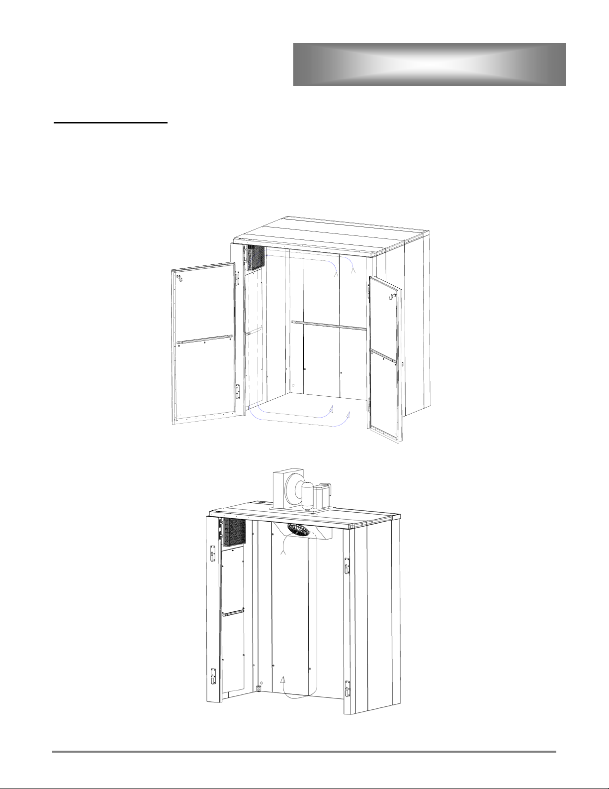
Theory of Operation
The Lang Proofer / Retarder is a controlled atmosphere chamber. Temperature and humidity can be set
independently to meet your particular proofing and retarding needs. In Proof mode air temperature is
increased as the air duct heater in energized. Humidity is increased as water is sprayed in the air duct. Air
is circulated continuously to provide positive movement from bottom to top, creating a uniform distribution
of warm, moist air in proof mode and cool air in retard mode.
Proofer Theory
Retarder Theory
ETL File E8138 Rev. A 2001
8
GENERAL OPERATION
DANGER
NOTICE
NOTICE
NOTICE
NOTICE
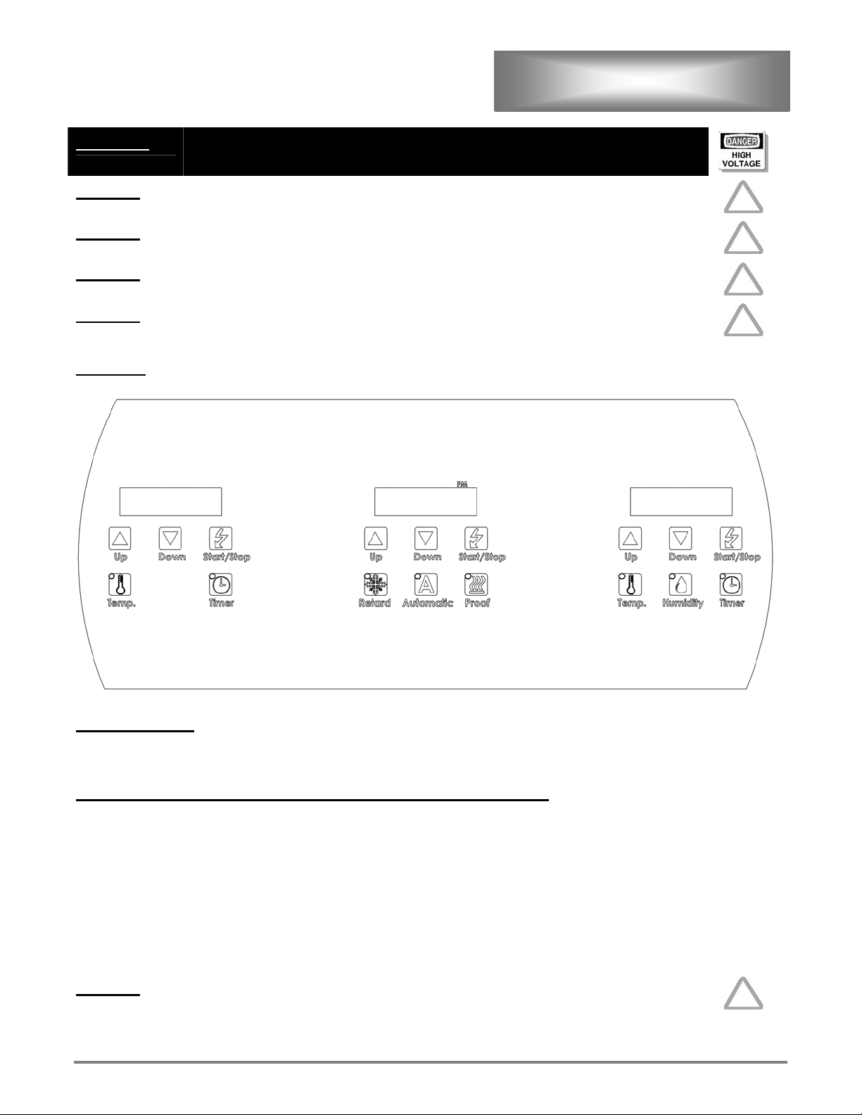
Controls
DO NOT STORE OR USE GASOLINE OR OTHER FLAMMABLE VAPORS OR
LIQUIDS IN THE VICINITY OF THIS OR ANY OTHER APPLIANCE.
For best results- Always allow your proofer to reach set temperature and
humidity before putting product in.
For best results- Proof at lower temperatures rather than higher.
To dry proof: Set humidity to the lowest setting (either 45% or less). At this
setting the humidity generator is turned off and will not produce humidity.
When the actual humidity is less than 46% display will show 45. When the
actual humidity is higher than 45%, display will show the actual humidity.
SETTING TIME
1. Press and hold the “Start / Stop” for 3-seconds.
2. Using the “Up”(10 minute increments) arrow or the “Down” (1 minute increments) arrows set the time.
RETARDER OPERATION (Unit will run in retard mode only)
1. Press “Retard” button, the Retarder side of the controls will come on.
2. Press “Temp.” button.
3. Set temperature to desired temperature (34°F-45°F) using the “Up” or “Down” buttons.
4. Press the “Timer” button.
5. Set time to desired time using the “Up” or “Down” buttons.
6. Place product in the Proofer / Retarder.
7. Press “Start / Stop” button and timer will begin counting down.
8. When buzzer sounds, press stop button and remove product from Proofer / Retarder.
9. To check actual temperature press “Temp.” button twice. Flashing display will indicate actual temp.
NOTICE
ETL File E8138 Rev. A 2001
The Retard mode will operate without using the timer if continuous
retarding is desired.
9

GENERAL OPERATION
POOFER OPERATION (Unit will run in proof mode only)
10. Press “Proof” button, the Proofer side of the controls will come on.
11. Press “Temp.” button.
12. Set temperature to desired temperature (70°F-120°F) using the “Up” or “Down” buttons.
13. Press “Humidity” button
14. Set Humidity to desired humidity (50%-100%) using the “Up” or “Down” buttons.
15. Press the “Timer” button.
16. Set time to desired time using the “Up” or “Down” buttons.
17. Place product in Proofer.
18. Press “Start / Stop” button and timer will begin counting down.
19. When buzzer sounds, press stop button and remove product from Proofer.
20. To check actual temperature press “Temp.” button twice. Flashing display will indicate actual temp.
21. To check actual humidity press “Humidity.” button twice. Flashing display will indicate actual
Humidity.
NOTICE
AUTOMATIC OPERATION (Unit will run in retard mode until a set time and then proof)
The Proof mode will operate without using the timer if continuous proofing
is desired.
1. Turn the Proofer / Retarder on and start the proof mode.
2. Set the desired proofing temperature and humidity.
3. To set Proofer start time, press and hold “Start / Stop” & “Proof” button at the same time for 3 seconds.
4. Set desired Proofer start time using “Up” and “Down” arrows.
5. Next set the slack time (or the time between when it exits Retarder mode and enters Proofer mode) To set slack time,
press and hold “Start / Stop” & “Automatic” button at the same time for 3 seconds.
6. Set desired slack time using “Up” and “Down” arrows. Example: A 90 minute slack time will read as 1:30 for one
hour and 30 minutes.
7. Place product in Proofer / Retarder and press the Automatic button. The unit will automatically go into Retarder
Mode. If for example it was 5:00pm and if the Proofer start time was 4:30am and if the slack time was 90 minutes.
The unit would be in Retarder mode all night until 3:00am, then the unit would turn off and the temperature would
slowly rise, and at 4:30 am the unit would start into Proofer mode.
ETL File E8138 Rev. A 2001
10
WARNING
GENERAL MAINTENANCE
THE LANG LRP SERIES PROOFER PRODUCES HUMIDITY WHICH WILL
NATURALLY CONDENSE AND ACCUMULATE WATER ON THE INTERIOR
FLOOR CAUSING IT TO BECOME SLIPPERY. ADJACENT EXTERIOR
FLOOR MAY ALSO BECOME SLIPPERY. USE EXTREME CAUTION WHEN
WALKING IN OR AROUND THIS APPLIANCE.
NOTICE
Service on this or any other LANG equipment must be performed by
qualified personnel only. Consult your authorized service agency directory
or call the factory at 1-800-224-LANG (5264), or WWW.LANGWORLD.COM
for the service agency nearest you
Every Day
Clean interior and exterior of proofer.
Every Six Months
Have factory authorized service personnel check proofer for proper temperature readings, air duct drain, heater plate,
spray nozzle.
As Needed
Clean interior and exterior walls and replace light bulb or any other components as needed.
Specifications
Temperature, humidity, and timer setting ranges:
Thaw:
70-120°F (18-66°C)
50-95% Relative Humidity
Proof:
Retard:
Timers:
Power:
Water:
ETL File E8138 Rev. A 2001
70-120°F (18-46°C)
50-95% Relative Humidity
34°-45°F (1°-8°C)
0-99 Hours and 0-59 Minutes
Varies depending on model and size (See data plate located on the underside of the valence
for the specific ratings or contact the factory for the information needed if the data plate is
not legible).
.73 gallons per hour maximum per air duct (2 ducts maximum) @ 30 PSI.
1.70 gallons per hour maximum per air duct (2 ducts maximum) @ 80 PSI.
11

Pre-Installation
Check the area where the Proofer is to be installed for the following:
No electrical junction boxes will be under the floor of the Proofer
Ceiling height above the Proofer should be sufficient to allow for installation. The minimum height
needed for installation is 95 inches.
Access is needed for an air-gap drain in any of the four corners.
Adequate space is needed in front of the Proofer to load and unload racks.
Local and national codes will require an electrical shut-off within a reasonable distance to the Proofer.
ASSEMBLY
ETL File E8138 Rev. A 2001
12
 Loading...