


INSTALLATION INSTRUCTIONS
AND
OWNER´S MANUAL
WARNING: If the information in these instructions are not followed exactly, a fire or explosion may result causing property damage, personal injury or loss of life.
—Do not store or use gasoline or other flammable vapors and liquids in the vicinity of this or any other appliance.
—WHAT TO DO IF YOU SMELL GAS
•Do not try to light any appliance.
•Do not touch any electrical switch; do not use any phone in your building.
•Immediately call your gas supplier from a neighbor's phone. Follow the gas supplier's instructions.
•If you cannot reach your gas supplier, call the fire department.
—Installation and service must be performed by a qualified installer, service agency or the gas supplier.
GRAVITY DIRECT VENT
WALL FURNACE
MODELS
MV 120
MV 130
MV 145
|
I |
G |
|
ES |
N |
||
D |
|
|
|
CERTIFIED
C |
E |
|
D |
|
E |
||
|
|
RT IFI |
|
EFFECTIVE DATE
APRIL, 2004
This appliance may be installed in an aftermarket, permanently located, manufactured home (USA only) or mobile home, where not prohibited by local codes.
This appliance is only for use with the type of gas indicated on the rating plate. This appliance is not convertible for use with other gases, unless a certified kit is used.
WARNING: If not installed, operated and maintained in accordance with the manufacturer's instructions, this product could expose you to substances in fuel or from fuel combustion which can cause death or serious illness.
MV1XX-2-0404 |
Page 1 |
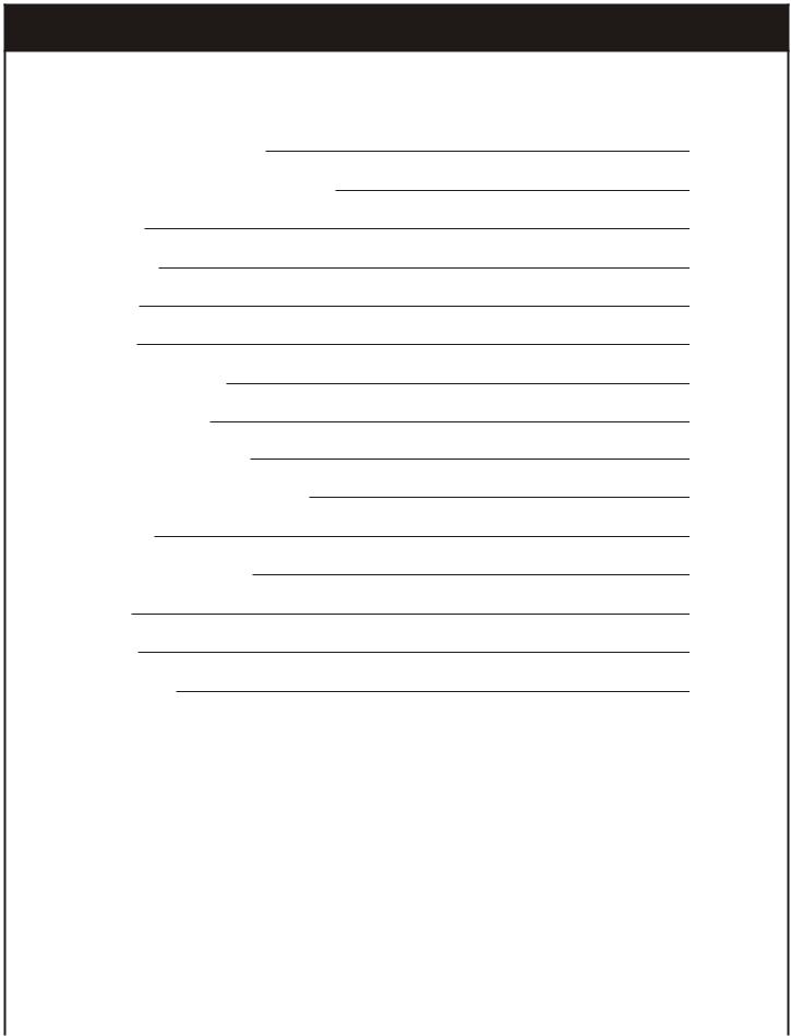
TABLE OF CONTENTS
SECTION |
PAGE |
|
|
Important Safety Information |
3 |
Safety Information for Users of LP Gas |
4 |
Introduction |
5 |
Specifications |
5 |
Gas Supply |
6 |
Clearances |
7-8 |
Installation Instructions |
8-10 |
Lighting Instructions |
11 |
Pilot Flame Characteristics |
12 |
Main Burner Flame Characteristics |
12 |
Maintenance |
12-13 |
How to Order Repair Parts |
13 |
Parts List |
14 |
Parts View |
15 |
Troubleshooting |
16 |
|
|
Page 2 |
MV1XX-2-0404 |

IMPORTANT SAFETY INFORMATION
THIS IS A HEATING APPLIANCE
DO NOT OPERATE THIS APPLIANCE WITHOUT FRONT PANEL INSTALLED.
• Due to high temperatures the appliance should be |
due to excessive lint from carpeting, bedding materials, |
|
located out of traffic and away from furniture and |
etc. It is imperative that control compartments, burners |
|
draperies. |
and circulating air passageways of the appliance be kept |
|
• Children and adults should be alerted to the hazards of |
clean. |
|
• DO NOT put anything around the furnace that will |
||
high surface temperatures and should stay away to avoid |
||
burns or clothing ignition. |
obstruct the flow of combustion and ventilation air. |
|
• Young children should be carefully supervised when |
• DO keep the appliance area clear and free from |
|
they are in the same room as the appliance. |
combustible material, gasoline and other flammable |
|
• Clothing or other flammable material should not be |
vapors and liquids. |
|
• DO examine venting system periodically and replace |
||
placed on or near the appliance. |
||
• Any safety screen or guard removed for servicing an |
damaged parts. |
|
• DO make a periodic visual check of pilot and burner. |
||
appliance must be replaced prior to operating the |
||
appliance. |
Clean and replace damaged parts. |
|
• Keep burner and control compartment clean. |
• CAUTION: Pilot hole cover must be kept tightly closed |
|
• Vent cap hot while furnace is in operation. |
during operation. |
|
• DO NOT use this heater if any part has been under |
||
• Installation and repair should be done by a QUALI- |
||
water. Immediately call a qualified service technician to |
||
FIED SERVICE PERSON. The appliance should be |
||
inspect the heater and to replace any part of the control |
||
inspected before use and at least annually by a qualified |
||
system and any gas control which has been under water. |
||
service person. More frequent cleaning may be required |
||
|
||
|
|
MV1XX-2-0404 |
Page 3 |

SAFETY INFORMATION FOR USERS OF LP-GAS
Propane (LP-Gas) is a flammable gas which can cause fires and explosions. In its natural state, propane is odorless and colorless. You may not know all the following safety precautions which can protect both you and your family from an accident. Read them carefully now, then review them point by point with the members of your household.
Someday when there may not be a minute to lose, everyone's safety will depend on knowing exactly what to do. If, after reading the following information, you feel you still need more information, please contact your gas supplier.
LP-GAS WARNING ODOR
If a gas leak happens, you should be able to smell the gas because of the odorant put in the LP-Gas. That's your signal to go into immediate action!
•Do not operate electric switches, light matches, use your phone. Do not do anything that could ignite the gas.
•Get everyone out of the building or area. Do that IMMEDIATELY.
•Close all gas tank or cylinder supply valves.
•LP-Gas is heavier than air and may settle in low areas such as basements. When you have reason to suspect a gas leak, keep out of basements and other low areas. Stay out until firefighters declare them to be safe.
•Use your neighbor's phone and call a trained LP-Gas service person and the fire department. Even though you may not continue to smell gas, do not turn on the gas again. Do not reenter the building or area.
•Finally, let the service man and firefighters check for escaped gas. Have them air out the area before you return. Properly trained LP-Gas service people should repair the leak, then check and relight the gas appliance for you.
NO ODOR DETECTED - ODOR FADE
Some people cannot smell well. Some people cannot smell the odor of the chemical put into the gas. You must find out if you can smell the odorant in propane. Smoking can decrease your ability to smell. Being around an odor for a time can affect your sensitivity or ability to detect that odor. Sometimes other odors in the area mask the gas odor. People may not smell the gas odor or their minds are on something else. Thinking about smelling a gas odor can make it easier to smell.
The odorant in LP-gas is colorless, and it can fade under
some circumstances. For example, if there is an underground
leak, the movement of the gas through soil can filter the
odorant. Odorants in LP-Gas also are subject to oxidation. This fading can occur if there is rust inside the storage tank or in iron gas pipes.
The odorant in escaped gas can adsorb or absorb onto or into walls, masonry and other materials and fabrics in a room. That will take some of the odorant out of the gas, reducing its odor intensity.
LP-Gas may stratify in a closed area, and the odor intensity could vary at different levels. Since it is heavier than air, there may be more odor at lower levels. Always be sensitive to the slightest gas odor. If you detect any odor, treat it as a serious leak. Immediately go into action as instructed earlier.
SOME POINTS TO REMEMBER
•Learn to recognize the odor of LP-gas. Your local LP-Gas Dealer can give you a "Scratch and Sniff" pamphlet. Use it to find out what the propane odor smells like. If you suspect that your LP-Gas has a weak or abnormal odor, call your LPGas Dealer.
•If you are not qualified, do not light pilot lights, perform service, or make adjustments to appliances on the LP-Gas system. If you are qualified, consciously think about the odor of LP-Gas prior to and while lighting pilot lights or performing service or making adjustments.
•Sometimes a basement or a closed-up house has a musty smell that can cover up the LP-Gas odor. Do not try to light pilot lights, perform service, or make adjustments in an area where the conditions are such that you may not detect the odor if there has been a leak of LP-Gas.
•Odor fade, due to oxidation by rust or adsorption on walls of new cylinders and tanks, is possible. Therefore, people should be particularly alert and careful when new tanks or cylinders are placed in service. Odor fade can occur in new tanks, or reinstalled old tanks, if they are filled and allowed to set too long before refilling. Cylinders and tanks which
have been out of service for a time may develop internal rust which will cause odor fade. If such conditions are suspected to exist, a periodic sniff test of the gas is advisable. If you have any question about the gas odor, call your LP-gas dealer. A periodic sniff test of the LPgas is a good safety measure under any condition.
•If, at any time, you do not smell the LP-Gas odorant and you think you should, assume you have a leak. Then take the same immediate action recommended above for the occasion when you do detect the odorized LP-Gas.
•If you experience a complete "gas out," (the container is under no vapor pressure), turn the tank valve off immediately. If the container valve is left on, the container may draw in some air through openings such as pilot light orifices. If this occurs, some new internal rusting could occur. If the valve is left open, then treat the container as a new tank. Always be sure your container is under vapor pressure by turning it off at the container before it goes completely empty or having it refilled before it is completely empty.
Page 4 |
MV1XX-2-0404 |

INTRODUCTION
Introduction
Always consult your local Building Department regarding regulations, codes or ordinances which apply to the installation of a direct vent wall furnace.
Instructions to Installer
1.Installer must leave instruction manual with owner after installation.
2.Installer must have owner fill out and mail warranty card supplied with furnace.
3.Installer should show owner how to start and operate furnace and thermostat.
Warning:
Any change to this furnace or its control can be dangerous. This is a heating appliance and any panel, door or guard removed for servicing an appliance must be replaced prior to operating the appliance.
General Information
This furnace is design certified in accordance with American National Standard/CSA Standard Z21.86b and CSA 2.32b2002 by the Canadian Standard Association, as a Gravity Direct Vent Wall Furnace to be installed on an outside wall according to these instructions.
Any alteration of the original design, installed other than as shown in these instructions or use with a type of gas not shown on the rating plate is the responsibility of the person and company making the change.
Important
All correspondence should refer to complete Model No., Serial No. and type of gas.
Notice: During initial firing of this unit, its paint will bake out and smoke will occur. To prevent triggering of smoke alarms, ventilate the room in which the unit is installed.
Installation in Residential Garages
Gas utilization equipment in residential garages shall be installed so that all burners and burner ignition devices are located not less than 18" (457 mm) above the floor.
Such equipment shall be located, or protected, so it is not subject to physical damage by a moving vehicle.
Qualified Installing Agency
Installation and replacement of gas piping, gas utilization equipment or accessories and repair and servicing of equipment shall be performed only by a qualified agency. The term "qualified agency" means any individual, firm, corporation or company which either in person or through a representative is engaged in and is responsible for (a) the installation or replacement of gas piping or (b) the connection, installation, repair or servicing of equipment, who is experienced in such work, familiar with all precautions required and has complied with all the requirements of the authority having jurisdiction.
The installation must conform with local codes or, in the absence of local codes, with the National Fuel Gas Code ANSI Z223.1/NFPA 54* Natural Gas and Propane Installation Code, CSA B149.1.
*Available from the American National Standards Institute, Inc., 11 West
42nd St., New York, NY 10036.
High Altitudes
For altitudes/elevations above 2,000 feet (609.9 m), input ratings should be reduced at the rate of 4 percent for each 1,000 (305m) feet above sea level. Canadian High Altitudes for locations having an elevation above mean sea level between 2,000 feet (609.9 m) and 4,500 feet (1370m), use orifices as indicated in the following table:
MOD |
0-2000feet (0-610 m) |
2000-4500 feet (610-1370 m) |
||
|
NG |
LPG |
NG |
LPG |
MV 120 |
0.053”(1.35 mm) |
0.035”(0.88 mm) |
0.050”(1.27 mm) |
0.033”(0.83 mm) |
MV 130 |
0.070”(1.77 mm) |
0.043”(1.10 mm) |
0.066”(1.67 mm) |
0.041”(1.03 mm) |
MV 145 |
0.077”(1.95 mm) |
0.053”(1.35 mm) |
0.072”(1.83 mm) |
0.050”(1.27 mm) |
SPECIFICATIONS
Model |
MV 145 |
MV 130 |
MV 120 |
Input BTU/HR (KW) |
20,000 (5.81) |
14,000 (4.07) |
8,400 (2.44) |
Min. Input BTU/HR (KW) |
6,900 (2.00) |
6,000 (1.74) |
3,800 (1.10) |
Efficiency Rating* (%) |
72% |
72% |
72% |
Height (inches / mm) |
24.4 / 620 |
24.4 / 620 |
24.4 / 620 |
Width (inches / mm) |
27.3 / 688 |
27.3 / 688 |
21.2 / 538 |
Depth (inches / mm) |
6.75 / 170 |
6.75 / 170 |
6.75 / 170 |
Gas Inlet |
3/8” NPT |
3/8” NPT |
3/8” NPT |
Input Vent Diameter (inches / mm) |
6 1/4” (160 mm) |
4 3/4” (121 mm) |
3 9/16” (90 mm) |
Output Vent Diameter (inches / mm) |
3 1/2” (89 mm) |
2 5/8” (67 mm) |
2 1/8” (54 mm) |
*The efficiency rating of the appliance is a product thermal efficiency determined under continuous operating conditions and was determined independantly of any installed system.
MV1XX-2-0404 |
Page 5 |

GAS SUPPLY
Locating Gas Supply
The gas line can enter the unit either through the floor or outside wall. The gas line opening should be made at this time. Location of the opening will be determined by the position of floor joists and the valve and union used for servicing.
Recommended Gas Pipe Diameter
Pipe Lenght |
Schedule 40 Pipe |
Tubing, Type L |
|||
(Feet) |
Inside Diameter |
Outside Diameter |
|||
|
|
|
|
|
|
|
Nat. |
L.P. |
Nat. |
L.P. |
|
0 - 10 |
1/2” |
3/8” |
1/2” |
3/8” |
|
1.3 cm |
1.0 cm |
1.3 cm |
1.0 cm |
||
|
|||||
10 - 40 |
1/2” |
1/2” |
5/8” |
1/2” |
|
1.3 cm |
1.3 cm |
1.6 cm |
1.3 cm |
||
|
|||||
40 - 100 |
1/2” |
1/2” |
3/4” |
1/2” |
|
1.3 cm |
1.3 cm |
1.9 cm |
1.3 cm |
||
|
|||||
100 - 150 |
3/4” |
1/2” |
7/8” |
3/4” |
|
1.9 cm |
1.3 cm |
2.2 cm |
1.9 cm |
||
|
|||||
Note: Never use plastic pipe. Check to confirm whether your local codes allow copper tubing or galvanized.
Note: Since some municipalities have additional local codes, it is always best to consult your local authority and installation code.
The use of the following gas connectors is recommended:
—ANS Z21.24 Appliance Connectors of Corrugated Metal Tubing and Fittings
—ANS Z21.45 Assembled Flexible Appliance Connectors of Other Than All-Metal Construction
The above connectors may be used if acceptable by the authority having jurisdiction. The state of Massachusetts requires that a flexible appliance connector cannot exceed three feet in length.
FLEXIBLE GAS LINE CONNECTION
Gas |
Flare Shut |
Tee |
Flex |
Flare Fitting |
NPT Niple |
Supply |
Off Valve |
Handle |
Tubbing |
|
|
|
RIGID GAS LINE CONNECTION |
|
|
Tee Handle |
|
NPT Gas |
Shut Off Close Niple NPT Union NPT Niple |
|
Supply |
Valve |
Figure 1 |
|
|
|
Consult the current National Fuel Gas Code, ANSI Z223.1 CAN/CGA-B149 (.1 or .2) installation code.
Installing a New Main Gas Cock
Each appliance should have its own manual gas cock. In the state of Massachusetts the gas cock must be a T handle type. A manual main gas cock should be located in the vicinity of the unit. Where none exists, or where its size or location is not adequate, contact your local authorized installer for installation or relocation.
Compounds used on threaded joints of gas piping shall be resistant to the action of liquefied petroleum gases. The gas lines must be checked for leaks by the installer. This should be done with a soap solution watching for bubbles on all exposed connections, and if unexposed, a pressure test should be made.
Never use an exposed flame to check for leaks. Appliance must be disconnected from piping at inlet of control valve and pipe capped or plugged for pressure test. Never pressure test with the appliance connected; control valve will sustain damage!
A gas valve and ground joint union should be installed in the gas line upstream of the gas control to aid in servicing. It is required by the National Fuel Gas Code that a drip line be installed near the gas inlet. This should consist of a vertical length of pipe tee connected into the gas line that is capped on the bottom in which condensation and foreign particles may collect.
Gas supply inlet
Alternate locations for shut off valve
3” (76 mm)
DRIP LEG
Figure 2
Pressure Testing of the Gas Supply System
1.To check the inlet pressure to the gas valve, a 1/8" (3 mm) N.P.T. plugged tapping, accessible for test gauge connection, must be placed immediately upstream of the gas supply connection to the appliance.
2.The appliance and its individual shutoff valve must be disconnected from the gas supply piping system during any pressure testing of that system at test pressures in excess of 1/2 psig (3.5 kPa).
3.The appliance must be isolated from the gas supply piping system by closing its individual manual shutoff valve during any pressure testing of the gas supply piping system at test pressures equal to or less than 1/2 psig (3.5 kPa).
Attention! If one of the above procedures results in pressures in excess of 1/2 psig (14" w.c.) (3.5 kPa) on the appliance gas valve, it will result in a hazardous condition.
Checking Manifold Pressure
Both Propane and Natural gas valves have a built-in pressure regulator in the gas valve. Natural gas models will have a manifold pressure of approximately 4.0" w.c.(0.996 kPa) for MV120 and 130 or 6.0" w.c.(1.494 kPa) for MV145 at the valve outlet with the inlet pressure to the valve from a minimum of 5.0" w.c.(1.245 kPa) for MV120 and 130 or 7.0" w.c.(1.742 kPa) for MV145 for the purpose of input adjustment to a maximum of 10.5" w.c.(2.61kPa). Propane gas models will have a manifold pressure approximately 10.0" w.c.(2.49kPa) at the valve outlet with the inlet pressure to the valve from a minimum of 11.0" w.c.(2.739kPa) for the purpose of input adjustment to a maximum of 13.0" w.c.(3.237kPa). A 1/8" (3mm) N.P.T. plugged tapping, accessible for test gauge connection, is located on the outlet side of the gas control.
Page 6 |
MV1XX-2-0404 |

CLEARANCES
1.In selecting a location for installation, it is necessary to provide adequate accessibility clearances for servicing and proper installation. In order to that, at least 6”(152 mm) should be left clear from the wall on right side of the cabinet and 4” (101 mm) on left side.
2.Unit is supported by a wall support plate secured to the wall.
3.The minimum clearances from casing to combustible construction is 36" (914 mm) on top, 4" (102 mm) on each side and 4" (102 mm) from the floor or from the top surface of carpeting, tile or other floor covering and 0" (0 mm) to rear wall.
4.The minimum distance from the center of the vent cap to the nearest outside corner or obstruction is 16" (407 mm).
5.The MV 120, MV 130 and MV 145 minimum wall depth is 4 1/2”(114 mm) and the maximum is 12”(305 mm). The
use of tubes not supplied by the manufacturer results in unsatisfactory performance.
The vent cap of a direct vent appliance, with an input of 10,000 Btu/h (3 kW/h) or less shall be located at least 6" (150 mm) from any opening through which flue gases could enter a building; for appliances up to 50,000 Btu/h (14.6 KW/h) this distance shall be at least 9" (229 mm). The bottom of the vent cap and the air intake shall be located at least 12" (305mm) above grade.
WARNING: The nearest point of the vent cap should be a minimum horizontal distant of six (6) feet (1.83m) from any pressure regulator. In case of regulator malfunction, the six (6) feet (1.83m) distance will reduce the chance of gas entering the vent cap.
G 
D A
E
B
L
 C
C
F
A
Vent terminal clearances
V
X
Vent teminal
Air supply
Area where terminal is not permitted
Figure 3
|
|
CANADIAN INSTALLATIONS1 |
|
US INSTALLATIONS2 |
||
|
|
|
|
|
||
A= clearance above grade, veranda, porch, deck |
|
12” (30 cm) |
|
12” (30 cm) |
||
or balcony |
|
|
|
|
|
|
B= clearance to window or door that may |
|
6” (15 cm) for appliances < 10,000 Btu/h |
|
6” (15 cm) for appliances < 10,000 Btu/h |
||
be opened |
(3 kW), 12” (30 cm) for appliances > 10,000 |
(3 kW), 9” (23 cm) for appliances > 10,000 |
||||
|
Btu/h (3 kW) and < 100,000 Btu/h (30 kW) |
Btu/h (3 kW) and < 50,000 Btu/h (15 kW) |
||||
|
|
|
|
|
|
|
C= clearance to permanently closed window |
|
|
|
|
|
|
|
|
|
|
|
|
|
|
|
|
|
|
|
|
D= vertical clearance to ventilated soffit located |
|
|
|
|
|
|
above the terminal within a horizontal distance |
|
|
|
|
|
|
of 2 feet (61 cm) from the center line |
|
clearance in accordance with local |
|
|
clearance in accordance with local |
|
of the terminal |
|
installation codes and the |
|
|
installation codes and the |
|
|
|
|
|
|
|
|
E= clearance to unventilated soffit |
|
requirements of the gas supplier |
|
|
requirements of the gas supplier |
|
|
|
|
|
|
|
|
F= clearance to outside corner |
|
|
|
|
|
|
G= clearance to inside corner |
|
|
|
|
|
|
|
|
|
|
|
|
|
|
|
|
|
|
|
|
H= clearance to each side of center line extended |
3 feet (91 cm) within a height 15 feet (4.5 m) |
|
|
|
||
|
clearance in accordance with local |
|
||||
above meter/regulator assembly |
|
above meter/regulator assembly |
|
|
||
|
|
installation codes and the |
|
|||
I= clearance to service regulator vent outlet |
|
3 feet (91 cm) |
|
requirements of the gas supplier |
|
|
|
|
|
|
|
|
|
MV1XX-2-0404 |
Page 7 |

INSTALLATION INSTRUCTIONS
Location of Furnace
The heater must be on an outside wall in the room to be heated. When choosing a location for the furnace please remember that the vent cap supplied with the unit must be installed without alteration, with the exception of cutting the vent tubes and insulation to length, as directed in these instructions. The outside vent cap needs to be flush to the wall, so select a relatively smooth exterior surface.
Since this appliance is a direct vent (balanced flue) design, all combustion and ventilation air is drawn from outside of the structure. No special considerations for combustion are necessary inside the structure. Once you have determined that the exterior vent will meet the clearances above, you must locate the heater on the inside wall of the room to be heated. Begin the installation by locating the wall studs on the inside wall of the structure. Find the centerlines between the studs where you want the unit to be mounted.
Locating Wall Opening
A full scale template is furnished with the unit which illustrates the vent and gas supply openings and mounting holes in their correct locations on the wall.
Note: the figure 4 gives the required dimensions for mounting the unit, in the event that the template is unusable or lost.
Place the template on the wall so that the vent opening will be located between the studs and, in the case of the MV 130, for example, the bracket mounting holes are over the studs (16” / 406 mm, on center). DO NOT CUT THE WALL STUDS IN ORDER TO INSTALL THE UNIT. Place the bottom edge of the template directly on the floor or the floor covering such as carpeting or tile.
Installing the Unit
Make sure that the location you have selected for the furnace complies the requirements above before its installation.
This gas appliance must not be connected to a chimney flue
serving a separate solid-fuel burning appliance.
Cutting the Vent Hole
Begin the installation by locating the wall studs on the side wall of the structure. Find the centerlines between the studs where you want the unit to be mounted. Refer to the following illustration (Figure 5) for a side view of how the finished installation should look. This appliance is certified for installation on walls which are a maximum of 12” (305 mm) thick. The vent assembly supplied with the unit will accomodate walls up to that thickness.
With the template flat and level against the inside wall, mark the location for the opening for the vent assembly as well as the location of the two holes for mounting the wall support plate and the one for the gas supply, if the supply is to be through the wall. If desired, (and in accordance with all applicable building and plumbing codes) the gas piping can be brought into the room through the floor underneath the unit.
Remove the template from the wall and with a long drill, make a hole in the center of the opening for ventilation all the way through inside and outside wall. Trace the wall opening in
INSTALLATION INSTRUCTIONS (cont.)
the indicated diameter in both walls and cut them. Your hole will be about 1 to 2” (26 to 52 mm), depending on the unit model, larger in diameter than the vent pipe.
Pilot burner viewing
Make sure the two holes (in the inside and the outside wall) are concentric to one another and line up. If the opening in the outside wall is higher than the opening in the inside wall, water from rain or from lawn sprinklers could enter the vent cap and drip back into the heater, causing it to rust out. Use a carpenter´s level and square to confirm that the two holes are level and in line with one another.
If the vent cap is to be installed on shingles or clapboards, or if it appears that a projection within 6” (152.4 mm) of the air inlet section could shield the air inlet, the entire vent should be supported away from the wall as shown in Figure 6.
wall and fasten the vent cap to the wall using the 4 screws (provided with the unit) in the holes prepared in the vent cap plate.
Making certain that the vent cap is flushed to the outer wall, draw a line all the way around the vent pipe where it comes through the inside wall. (Note: this line only marks the point where the pipe comes through the wall. It is not where you will cut the pipes).
Remove the vent assembly from the wall. Measure 7/ 16” (11 mm) from the line just made and make a mark towards the open end of the pipe.
Mark several spots around the pipe insulation at this 7/ 16” (11mm) distance and then tape a sheet of paper around the pipe at this time to assure an even cut.
Use a cutter knife to cut only the insulation and its lining and a hack saw or tin snips to cut the larger pipe at the cut line on the edge of the paper.
Cut a clean, straight line on the outside tube, being careful not to crimp or deform the tube.
It is very important that this be a clean straight cut for the
heater to perform properly.
On MV 120 and MV 130 units, you must proceed to cut the insulation again through the line originally traced (flush line of the inner wall, 7/16” back from the cut end of the tube). (See drawing)
On MV145 units, you must proceed to cut the lower edge of the insulation (only this part, not the complete circumference) to allow the ventilation come through the wall mounting support bar. Cut according following drawing:
Support
box
Vent cap
Figure 6
For vinyl siding installation, order the appropriated kit through the Parts Department.
Note: the vent assembly of MV 145 units has off-centre tubes and must be installed in a certain position. Make sure the arrow engraved on its ring is located in the upper position. If not, connecting the inner pipe in the appliance won´t be possible.
Marking and cutting the vent pipes to the proper length
From the outside of the building, push the vent assembly
through the hole until the vent cap flange is against the outer
Figure 7
Measure now 2” (50.8 mm) from the cut end of the larger pipe and make a mark on the inner pipe. Be certain that the inner pipe is thoroughly marked so that it will be 2” (50.8 mm) longer than the larger pipe when cut. The inner pipe needs to be cut with a hacksaw.
Remember to remove the vent assembly from the wall in order to cut the tubes
Installing the vent assembly and wall support plate
In case outside wall is of tiled wood construction, rough or
unlevelled, the use of silicone sealing compound to avoid

INSTALLATION INSTRUCTIONS (cont.)
Figure 8
eventual water filtration or the entrance of bugs is necessary.
Press the flange against the outer wall surface and fasten the vent cap to the wall using the 4 screws (provided with the unit) in the holes prepared in the vent cap plate. Once the vent is secured to the wall, proceed filling the gaps between the vent plate and the wall with silicone sealing compound.
Inside the building, place the wall support plate (which is taped inside the cabinet during shipment) over the open end of the vent pipe and push the plate firmly against the interior wall.
You might need to handle the introduction of the larger pipe into the hole of the support plate with your fingers since the pipe could have suffered some minor deformation through the cutting process.
Now level the plate with carpenter level and mark the mounting holes with a pencil (see Figure 8). Remove the wall support plate from the vent pipe and drill the two holes with the appropriate drill bit.
Place the wall support plate over the vent pipe again and affix the plate to the wall using the two screws provided with the unit.
Note: hollow wall fasteners (also supplied with the unit) are necessary for model MV 120. Models MV 130 and MV 145 can be mounted on the wall studs.
Mounting the furnace
Take off the cover by loosening the two screws at the bottom. Pull the bottom away from the heater and lift it up off the tabs on top.
Figure 9
Important: remove styrofoam inside front cover now.
Remove the small piece of wood from the rear of the heater and discard. Four small adhesive foam pads are included with the unit and can be found in the accessory bag. Place the foam pads on the four raised “bumps” on the rear of the unit. These foam pads will protect the wall surfaces from damage.
Hang the heater on the arms on the wall support bracket, taking extreme care to ensure that the small diameter vent pipe fits inside the smaller opening in the rear of the unit. (See Figure 9). The larger diameter vent pipe must then slide over the outside flange opening.
Warning: the heater will not function properly if these
connections are not tight and clean. Secure the unit to the wall support bracket with the two screws provided.
Attach the Lighting Instructions to the back of the unit so that they may be read when necessary. These instructions are for current and future use. Make sure they remain accesible after the unit is installed.
Connecting the gas supply
Connect the gas supply to the 3/8” (9.5 mm) pipe on the lower part of the right side of the heater by using standard connectors. Please refer to the cautionary remarks noted in the beginning of this manual.
After connecting the gas supply to the gas control on the
heater, the connections must be checked thoroughly for
leaks. With the shut-off valve turned ON, but the gas control knob on the heater OFF, apply liberal amounts of a soapy water solution to all of the piping joints. A gas leak will cause bubbles to form. Note any leaks in the piping system, then shut off the gas at the shut-off valve, or at the gas meter or propane/LP tank serving the building. Fix the leaking joint and re-test the joints as directed above.
Once the supply is checked and does not leak, place the cover on the unit. See Figure 10. Be sure the foam packing has been removed. Secure the cover with the two nuts at the bottom of the unit which you had removed when unpacking.
LIGHTING INSTRUCTIONS
 FOR YOUR SAFETY READ BEFORE LIGHTING
WARNING: If you do not follow these instructions exactly, a fire or explosion may result causing property damage, personal injury or loss of life.
A.This appliance has a pilot which must be lighted by hand. When lighting the pilot, follow these instructions exactly.
B.BEFORE LIGHTING smell all around the appliance area for gas. Be sure to smell next to the floor because some gas is heavier than air and will settle on the floor.
WHAT TO DO IF YOU SMELL GAS
•Do not try to light any appliance.
•Do not touch any electrical switch; do not use any phone in your building.
•Immediately call your gas supplier from a neighbor's
phone. Follow the gas supplier's instructions.
•If you cannot reach your gas supplier, call the fire department.
C.Use only your hand to push in or turn the gas control knob. Never use tools. If the knob will not push in or turn by hand, don't try to repair it; call a qualified service technician. Force or attempted repair may result in a fire or explosion.
D.Do not use this appliance if any part has been under water. Immediately call a qualified service technician to inspect the appliance and to replace any part of the control system and any gas control which has been under water.
 LIGHTING INSTRUCTIONS
1.STOP! Read the safety information above.
2.Set the thermostat to the lowest setting.
3.Open the control access panel on the top right side of the unit.
4. Turn thegas control knobclockwise |
|
tothe OFFposition. |
|
CONTROL KNOB |
|
|
|
INDICATOR |
|
|
|
|
|
1 |
|
5 |
|
2 |
|
4 |
3 |
||
GAS CONTROL KNOB |
|||
|
SHOWN IN OFF POSITION
5.Wait five (5) minutes to clear any gas. If you then smell gas, STOP! Follow “B” in the safety information above in this label. If you don´t smell gas, go to the next step.
6.Locate the red pushbutton Piezo igniter directly behind the gas control knob.
PILOT |
THERMOCOUPLE |
7. Turn the gas control knob counter clockwise to the
PILOT position. Depress the gas control knob and push in
the Piezo igniter several times, until the pilot is lit. The pilot flame can be observed by looking down the inside of the heater jacket. A small reflector on the right hand side near
the bottom should allow you to see if the pilot is lit. Removal
of the outer painted jacket of the heater will allow direct
visual observation of the pilot and burner.
8.Continue to depress the gas control knob for at least 30 seconds or until the pilot remains lit. When you release the gas control knob, it should pop back up. Pilot should remain lit.
-If the knob does not pop up when released, stop and immediately call your service technician or gas supplier.
-If the pilot will not stay lit after several tries, turn the gas control knob to the OFF position and call your service technician or gas supplier.
9.Attention! Gas control knob has an INTERLOCK latching device. When the pilot is initially lit and the safety magnet is energized (pilot stays ON) the interlock latching device becomes operative. If the gas control is turned to the OFF position or gas flow to the appliance is shut off, the pilot cannot be relighted until the safety magnet is de-energized (approximately 60 seconds). There will be an audible “click” when the safety magnet in the gas control is de-energized. Pilot can now be relighted. Repeat steps 4 through 8.
10.Replace the front painted cover (if removed).
11. Turn the gas knob counter clockwise |
to the desired |
temperature setting.
12. Close the control access door.
 TO TURN OFF GAS TO APPLIANCE
1.Set the thermostat to lowest setting.
2.Open the control access panel on the top right side of the unit.
3. Turn the gas knob clockwise |
to the OFF position. Do |
not force. |
|
4. Close the control access panel.
WARNING: After turning off wait 5 minutes before trying to relight.
MV1XX-2-0404 |
Page 11 |

PILOT FLAME CHARACTERISTICS
The correct flame will be almost horizontal, blue and will extend past the thermocouple 1/4" (6 mm). The flame will surround the thermocouple just below the tip.
Flame must extend past the thermocouple
Pilot
On propane (LP-gas) slight yellow might occur where the pilot flame and burner flame meet.
Natural gas pilots require adjusting when the inlet pressure is above 5" w.c. (1.25kPa). Turn adjustment screw clockwise to reduce flame.
Propane (LP-gas) will not require adjusting.
Thermocouple
Figure 11
MAIN BURNER FLAME CHARACTERISTICS
There will be a short blue inner flame with a much larger lighter blue secondary flame. The burner flame may have a yellow tip when hot. See the burner drawing showing the approximate heights of each part of the flame. Dust in the combustion air will produce an orange or red flame. Do not mistake the orange or red flame for an improper yellow flame. After use, cleaning may be required for the proper flame.
Burner flame
Primary flame 1/4” (6 mm) to 1/2” (13 mm)
Figure 12
Secondary flame 4” (102 mm) to 6” (152 mm)
MAINTENANCE
The appliance should be inspected and cleaned before using each year by a qualified service person.
Warning: the following instructions are designed to direct a qualified technician through the proper periodic maintenance and repair which may be required throughout the expected life of this unit. NO attempt should be made by the homeowner
to perform these functions.
1.Remove the cover from the unit by removing the two nuts at the bottom of the unit.
2.The gas supply should be turned OFF at the shut-off valve in the supply piping leading to the appliance (if installed), or at the gas meter or propane/ LP tank. The gas to the unit should be disconnected so the unit can be removed from the wall.
3.Remove the two screws which hold the unit to the wall support plate and lift and pull the unit away from the wall.
4.Carefully examine the interior of the vent pipes, both large and small diameter. If you notice any blockage or obstruction, clean the pipes.
5.Look inside the openings of the rear of the unit and check for any foreign materials. Remove any objects which may block or obstruct the free flow of combustion and ventilation air. You will only be able to see a portion of the interior of the unit from this angle.
6.The main burner and pilot burner can be removed from the unit for cleaning by first loosening the compression fittings
that supply gas to both the main burner and pilot. Note: before removing either the pilot assembly or main burner assembly be sure to have replacement gaskets on hand. See Figure 13. After unscrewing the gas connection to the burner and removing the compression nuts, unscrew the thermocouple from the base of the pilot and remove it from the pilot assembly. Remove the four screws which hold the main burner/pilot plate in place, and withdraw the burner/pilot from the unit. Check the burner/pilot for dirt, lint, or a black powdery carbon deposit. If any is noted, brush it off completely using a soft bristled brush, or blow it
Thermocouple
Screws that hold the main burner/pilot
plate in place
Gas connection to the burner
Figure 13
Page 12 |
MV1XX-2-0404 |

MAINTENANCE (cont.)
out. Do not attempt to pass anything through the pilot orifice. Next, check the main burner for dirt, lint or carbon deposits. Again, if any is noted, clean with a soft brush.
7.Inspect the interior of the combustion chamber for dirt, lint or carbon deposits. If any are found, loosen them with a long handled brush and remove the residue from the heater with a vacuum cleaner.
8.In preparation for replacing the main burner/pilot, check the condition of the gasket on the mounting plate. If the gasket appears damaged or worn, replace ONLY with a gasket available from Empire Comfort Systems Inc., whose address is at the bottom of this page. Install the assembly in the heater and re-secure the assembly to the heater chassis with the four screws removed in step 6 above. Note: verify that the left side of the main burner is mounted on its support bracket. The burner should be level.
9.Reconnect the main burner and pilot gas lines which were disconnected in step 6 above. Reinstall the thermocouple in the pilot bracket, inserting it fully into chamber before tightening.
10.Replace the heater on the wall support bracket, taking extreme care to ensure that the small diameter vent pipe is firmly engaged with the vent outlet at the rear of the heater. The large diameter vent pipe will slide over the appropriate opening. Resecure the unit to the bracket with the two screws removed earlier.
11.Reconnect the gas supply piping and REPEAT THE LEAK TEST PROCEDURE. In addition, it will be necessary for you to check the gas connections inside the unit for leaks. After testing the gas connections to the unit, place the pilot burner into operation by following the instructions found in this manual or on the hanging tag behind the unit. Che ck all joints to the pilot gas line with a soapy water solution. Bubbles on any of the joints indicated a leak is present and must be repaired. Turn OFF the gas to the unit when performing any repairs to the gas piping system. After the pilot lines are checked, turn the main burner ON and again check all joints in the piping system for leaks with soapy water. Repair any joints which indicate a leak is present.
12.While the main burner is ON, check the pilot and burner flames to see that they are burning a clean blue color. See Figures 11 and 12 for an approximation of the correct flame pattern. If your unit is not burning cleanly, or if you are not sure, turn the unit OFF and contact the gas supplier or call Empire Comfort Systems Inc..
Before completing your periodic maintenance checkout, ensure that the appliance area is clear and free from combustible materials, gasoline, and other flammable vapors or liquids. Also check to see that the flow of combustion and ventilation air around the vent cap on the outside of the structure is not obstructed.
Note: verify proper operation after servicing.
HOW TO ORDER REPAIR PARTS
Parts can be ordered only through your service person or dealer. For best results, the service person or dealer should order parts through the distributor. Parts can be shipped directly to the service person/dealer.
All parts listed in the Parts List have a Part Number. When ordering parts, first obtain the Model Number from the name plate on your equipment. Then determine the Part Number (not the Index Number) and the Description of each part from the following appropriate illustration and list. Be sure to give all this information . . .
Furnace Model Number |
|
|
Part Description |
|
|
|
|
|
|||
Furnace Serial Number |
|
|
Part Number |
|
|
Type of Gas (Propane or Natural) |
|
|
|
|
|
Do not order bolts, screws, washers or nuts. They are standard hardware items and can be purchased at any local hardware store.
Shipments contingent upon strikes, fires and all causes beyond our control.
Empire Comfort Systems, Inc. Nine Eighteen Freeburg Ave. Belleville, IL 62222-0529
MV1XX-2-0404 |
Page 13 |

PARTS LIST
PLEASE NOTE: When ordering parts, it is very important that part number and description of part coincide
USE ONLY MANUFACTURER'S REPLACEMENT PARTS. USE OF ANY OTHER PARTS COULD CAUSE INJURY OR DEATH.
No. |
PART NAME |
PART N° / MV 120 |
PART N° / MV 130 |
PART N° / MV 145 |
1a |
Vent Assy. (6” to 12” / 152.4 to 304.8 mm) |
SD43019400 |
SD43018500 |
SD43018400 |
1b |
Vent Assy. (12” to 18” / 305 to 460 mm) |
SD430194B0 |
SD430185B0 |
SD430184B0 |
2 |
Wall Support Plate |
SD44221800 |
SD442202B0 |
SD44326100 |
3 |
Combustion Chamber |
SK00000047 |
SK00000048 |
SK00000049 |
4 |
Cover |
SK00000050 |
SK00000051 |
SK00000052 |
5 |
Main Burner Assembly |
SD44108300 |
SD44107500 |
SD43107900 |
6 |
Pilot Burner |
SD44105800 |
SD44105800 |
SD44105800 |
7 |
Thermocouple |
SD44305500 |
SD44305500 |
SD44305500 |
8a |
Gas Control Nat. Gas |
SD44177000 |
SD44177000 |
SD44177000 |
8b |
Gas Control LP Gas |
SD44176900 |
SD44176900 |
SD44176900 |
9 |
Piezo Igniter |
SD44175800 |
SD44175800 |
SD44175800 |
10 |
Piezo Wire |
SD44120800 |
SD44120800 |
SD44120800 |
11 |
Pilot Igniter Electrode |
SA00000263 |
SA00000263 |
SA00000263 |
12 |
Gasket for Viewing Window |
SD44107002 |
SD44107002 |
SD44107002 |
13 |
Mica for Viewing Window |
SD44107100 |
SD44107100 |
SD44107100 |
14 |
Frame for Viewing Window |
SD44106900 |
SD44106900 |
SD44106900 |
15 |
Mirror for Viewing Window |
SD44106801 |
SD44106801 |
SD44106801 |
16 |
Pilot Tubing |
SK00000053 |
SK00000053 |
SK00000053 |
17 |
Main Burner Tubing |
SK00000054 |
SK00000054 |
SK00000054 |
18 |
Burner Support Plate |
SD44106100 |
SD44106100 |
SD44106100 |
19 |
Pilot Burner Gasket |
SD44158001 |
SD44158001 |
SD44158001 |
20 |
Main Burner Gasket |
SD44158102 |
SD44158102 |
SD44158102 |
21a |
Burner Orifice Natural |
SD44125400 |
SD44125500 |
SD443215A0 |
21b |
Burner Orifice LP Gas |
SD44125700 |
SD44125200 |
SD443215B0 |
22a |
Burner Orifices for 2000-4500 ft (610- |
SD443332A0 |
SD443332C0 |
SD443215C0 |
|
1370 m) altitude Nat. Gas |
|
|
|
22b |
Burner Orifices for 2000-4500 ft (610- |
SD443332B0 |
SD443332D0 |
SD443215D0 |
|
1370 m) altitude LP. Gas |
|
|
|
23a |
Pilot Burner Orifice Natural |
SD44111300 |
SD44111300 |
SD44111300 |
23b |
Pilot Burner Orifice LP Gas |
SD44132400 |
SD44132400 |
SD44132400 |
24a |
Minimum Rate Screw Nat. |
SD44131900 |
SD44152900 |
SD44152900 |
24b |
Minimum Rate Screw LPG |
SD44131600 |
SD44153000 |
SD44153000 |
25 |
Gas Valve Connection Kit |
SK00000055 |
SK00000055 |
SK00000055 |
|
|
|
|
|
Page 14 |
MV1XX-2-0404 |

PARTS VIEW
MV1XX-2-0404 |
Page 15 |
 Loading...