

Page 1
Installation, Operation, Concept Training, Maintenance, &
Troubleshooting
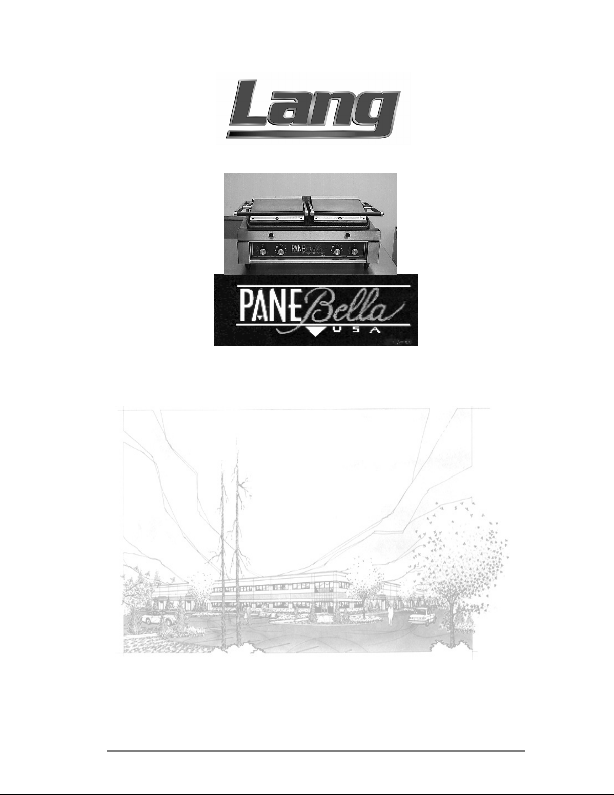
Model: PANE BELLA PB-24 & PANE BELLA UNO PB-12
Lang Manufacturing Company 6500 Merrill Creek Parkway Everett, WA 98203
Part Number: 60801-17 Phone: 425-349-2400 Fax: 425-349-2733
WWW.LANGWORLD.COM © Copyright 1999
1
Page 2
THIS MANUAL MUST BE RETAINED FOR FUTURE REFERENCE.
READ, UNDERSTAND AND FOLLOW THE INSTRUCTIONS AND
WARNINGS CONTAINED IN THIS MANUAL.
FOR YOUR SAFETY
DO NOT STORE OR USE GASOLINE OR OTHER FLAMMABLE
VAPORS AND LIQUIDS IN THE VICINITY OF THIS OR ANY
OTHER APPLIANCE.
POST IN A PROMINENT LOCATION
WARNING: IMPROPER INSTALLATION, ADJUSTMENT,
ALTERATION, SERVICE OR MAINTENANCE CAN CAUSE
PROPERTY DAMAGE, INJURY OR DEATH. READ THE
INSTALLATION, OPERATING AND MAINTENANCE
INSTRUCTIONS THOROUGHLY BEFORE INSTALLING OR
SERVICING THIS EQUIPMENT.
Model #: Purchased From:
Serial #:
Location:
Date Purchased:
Purchase Order #:
Date Installed:
For Service, Call:
2
Page 3

TABLE OF CONTENTS
CHAPTER PAGE
1. TABLE OF CONTENTS ...............................................................................3
2. READ FIRST .................................................................................................4
3. EQUIPMENT DESCRIPTION ...................................................................... 6
4. UNPACKING................................................................................................. 8
5. INSTALLATION ........................................................................................... 9
6. INITIAL START-UP......................................................................................11
7. OPERATION.................................................................................................. 12
8. MAINTENANCE & CLEANING PROCEDURES...................................... 14
9. TROUBLESHOOTING .................................................................................16
10. PARTS LISTS................................................................................................ 18
11. WIRING DIAGRAMS................................................................................... 20
3
Page 4
IMPORTANT READ FIRST IMPORTANT
CAUTION: THE GRIDDLE PB-24 WEIGHS 130 LBS. (58.97
KILOGRAMS) & PB-12 WEIGHS 70 LBS. (31.75
KILOGRAMS). FOR SAFE HANDLING, INSTALLER
SHOULD OBTAIN HELP AS NEEDED, OR EMPLOY
APPROPRIATE MATERIALS HANDLING EQUIPMENT
(SUCH AS A FORKLIFT, DOLLY, OR PALLET JACK)
TO REMOVE THE UNIT FROM THE SKID AND MOVE
IT TO THE PLACE OF INSTALLATION.
CAUTION: ANY STAND, COUNTER OR OTHER DEVICE ON
WHICH THE GRIDDLE WILL BE LOCATED MUST BE
DESIGNED TO SUPPORT THE WEIGHT OF THE
GRIDDLE.
CAUTION: SHIPPING STRAPS ARE UNDER TENSION AND CAN
SNAP BACK WHEN CUT.
DANGER: THIS APPLIANCE MUST BE GROUNDED AT THE
TERMINAL PROVIDED. FAILURE TO GROUND THE
APPLIANCE COULD RESULT IN ELECTROCUTION
AND DEATH.
WARNING: INSTALLATION OF THE UNIT MUST BE DONE BY
PERSONNEL QUALIFIED TO WORK WITH
ELECTRICITY. IMPROPER INSTALLATION CAN
CAUSE INJURY TO PERSONNEL AND/OR DAMAGE
TO EQUIPMENT. UNIT MUST BE INSTALLED IN
ACCORDANCE WITH ALL APPLICABLE CODES.
NOTICE: The data plate is located on the back of each griddle.
The griddle voltage, wattage, serial number, wire
size, and clearance specifications are on the data
plate. This information should be carefully read and
understood before proceeding with the installation.
NOTICE: The installation of any components such as a vent
hood, grease extractors, fire extinguisher systems,
must conform to their applicable National, State and
locally recognized installation standards.
NOTICE: During the first few hours of operation you may
notice a small amount of smoke coming off the
griddle, and a faint odor from the smoke. This is
normal for a new griddle and will disappear after the
first few hours of use.
CAUTION: ALWAYS KEEP THE AREA NEAR THE APPLIANCE
FREE FROM COMBUSTIBLE MATERIALS.
CAUTION: KEEP FLOOR IN FRONT OF EQUIPMENT CLEAN
AND DRY. IF SPILLS OCCUR, CLEAN IMMEDIATELY,
TO AVOID THE DANGER OF SLIPS OR FALLS.
4
Page 5
IMPORTANT READ FIRST IMPORTANT
WARNING: KEEP WATER AND SOLUTIONS OUT OF CONTROLS.
NEVER SPRAY OR HOSE CONTROL CONSOLE,
ELECTRICAL CONNECTIONS, ETC.
CAUTION: MOST CLEANERS ARE HARMFUL TO THE SKIN, EYES,
MUCOUS MEMBRANES AND CLOTHING.
PRECAUTIONS SHOULD BE TAKEN TO WEAR RUBBER
GLOVES, GOGGLES OR FACE SHIELD AND
PROTECTIVE CLOTHING. CAREFULLY READ THE
WARNING AND FOLLOW THE DIRECTIONS ON THE
LABEL OF THE CLEANER TO BE USED.
WARNING: ALWAYS HOLD THE UPPER GRILL OPEN WHILE
CLEANING TO PREVENT INJURY IN CASE OF GRILL
CLOSING.
CAUTION: DO NOT USE ICE OR WATER TO CLEAN THE COOKING
SURFACE WHILE THE GRIDDLE IS HOT. THE GRILL IS
MADE OF CAST IRON AND MAY CRACK FROM A
NOTICE:
RAPID TEMPERATURE CHANGE.
Service on this, or any other, LANG appliance must be
performed by qualified personnel only. Consult your
authorized service station directory or call the factory at
1-800-224-LANG (5264), or WWW.LANGWORLD.COM
For the service station nearest you.
WARNING: BOTH HIGH AND LOW VOLTAGES ARE PRESENT
INSIDE THIS APPLIANCE WHEN THE UNIT IS
PLUGGED/WIRED INTO A LIVE RECEPTACLE. BEFORE
REPLACING ANY PARTS, DISCONNECT THE UNIT
FROM THE ELECTRIC POWER SUPPLY.
CAUTION: USE OF ANY REPLACEMENT PARTS OTHER THAN
THOSE SUPPLIED BY LANG OR THEIR AUTHORIZED
DISTRIBUTORS CAN CAUSE BODILY INJURY TO THE
OPERATOR AND DAMAGE TO THE EQUIPMENT AND
WILL VOID ALL WARRANTIES.
5
Page 6

EQUIPMENT DESCRIPTION
Lang Model: Lang Model: PB-24 & PB-12
PANE BELLA GRILL &
PANE BELLA UNO
Exterior Construction
PANE BELLA, PB-24
• The grill dimensions are 12.25” (31.12cm) High (allow an additional 13” (33.02cm)
for upper element swing, 14” (35.56cm) Deep, and 24” (60.96) Wide.
• The grill surface is made of two upper and one lower gray iron casting grill surfaces.
PANE BELLA UNO, PB-12
• The grill dimensions are 12.25” (31.12cm) High (allow an additional 13” (33.02cm)
for upper element swing, 14” (35.56cm) Deep, and 13.25” (33.66cm) Wide.
• The grill surface is made of an upper and lower gray iron casting grill surface.
Operation
• Each twelve-inch section has its own thermostat and timer.
Controls
• Each PANE BELLA Grill comes with controls which include:
An independently controlled thermostat for each section.
A separate timer for each section.
Technical
PB-24
• Grill operates on 208, 220, or 240 Volts. It is shipped with a Power Cord and Plug
attached.
• Counter space required is 14” (35.56cm) Deep, and 24” (60.96) Wide.
• The grill weighs 130 lbs. (58.97 kg).
PB-12
• Grill operates on 120. It is shipped with a power cord and standard plug attached.
• Counter space required is 14” (35.56cm) Deep, and 13.25” (33.66cm) Wide.
• The grill weighs 70 lbs. (31.75 kg).
6
Page 7
EQUIPMENT DESCRIPTION CONT’D
Ventilation and Clearances
Standard minimum clearance from combustible construction is as follows:
1 inches from sides
4 inches from back
4 inches from floor
The installation of any components such as a vent hood, grease extractors, and/or fire
extinguisher systems, must conform to the there applicable nationally recognized
installation standards.
Electrical Specifications
ELECTRICAL SPECIFICATIONS
Model Number Volts Watts Amps Wire
PB-24
208 3240 15.58 12 GA
220 3625 16.48 12 GA
240 4314 17.98 12 GA
PB-12
120 1620 13.5 12 GA
208 1620 7.79 12 GA
220 1812 8.24 12 GA
240 2157 8.99 12 GA
7
Page 8
UNPACKING
4.1 Receiving the Griddle
Upon receipt, check for freight damage, both visible and concealed. Visible
damage should be noted on the freight bill at the time of delivery and signed by the
carrier's agent. Concealed loss or damage means loss or damage which does not
become apparent until the merchandise has been unpacked. If concealed loss or
damage is discovered upon unpacking, make a written request for inspection by the
carrier's agent within 15 days of delivery. All packing material should be kept for
inspection. Do not return damaged merchandise to Lang Manufacturing Company.
File your claim with the carrier.
4.2 Location
Prior to un-crating, move the griddle as near its intended location as practical. The
crating will help protect the unit from the physical damage normally associated
with moving it through hallways and doorways.
4.3 Un-crating
The griddle will arrive completely assembled inside a wood frame covered by
cardboard box and strapped to a skid. Remove the cardboard cover, cut the
straps and remove the wood frame.
CAUTION: THE GRIDDLE PB-24 WEIGHS 130 LBS. (58.97
KILOGRAMS) & PB-12 WEIGHS 70 LBS. (31.75
KILOGRAMS). FOR SAFE HANDLING, INSTALLER
SHOULD OBTAIN HELP AS NEEDED, OR EMPLOY
APPROPRIATE MATERIALS HANDLING EQUIPMENT
(SUCH AS A FORKLIFT, DOLLY, OR PALLET JACK) TO
REMOVE THE UNIT FROM THE SKID AND MOVE IT TO
THE PLACE OF INSTALLATION.
CAUTION: ANY STAND, COUNTER OR OTHER DEVICE ON WHICH
THE GRIDDLE WILL BE LOCATED MUST BE
DESIGNED TO SUPPORT THE WEIGHT OF THE
GRIDDLE.
CAUTION: SHIPPING STRAPS ARE UNDER TENSION AND CAN
SNAP BACK WHEN CUT.
Remove griddle from skid and place in intended location.
8
Page 9

INSTALLATION
DANGER: THIS APPLIANCE MUST BE GROUNDED AT THE
TERMINAL PROVIDED. FAILURE TO GROUND THE
APPLIANCE COULD RESULT IN ELECTROCUTION AND
DEATH.
WARNING: INSTALLATION OF THE UNIT MUST BE DONE BY
PERSONNEL QUALIFIED TO WORK WITH ELECTRICITY.
IMPROPER INSTALLATION CAN CAUSE INJURY TO
PERSONNEL AND/OR DAMAGE TO EQUIPMENT. UNIT
MUST BE INSTALLED IN ACCORDANCE WITH ALL
APPLICABLE CODES.
NOTICE: The data plate is located on the back of each griddle. The
griddle voltage, wattage, serial number, wire size, and
clearance specifications are on the data plate. This
information should be carefully read and understood
before proceeding with the installation.
NOTICE: The installation of any components such as a vent hood,
grease extractors, fire extinguisher systems, must
conform to their applicable National, State and locally
recognized installation standards.
5.1 Electrical Connection
Follow the receptacle manufacturer’s instructions when connecting the receptacle
to the power supply.
The electrical connection must be made in accordance with local codes or in the
absence of local codes with NFPA No. 70 latest edition (in Canada use: CSA STD.
C22.1).
The electrical service entrance is provided by a cord and plug located at the rear of
the appliance.
The plug provided with the PB-24 is a L6-30P, PB-12 is standard. The receptacle
must be supplied by the installer and for a PB-24 is a L6-30R, PB-12 is standard.
Supply wire size must be large enough to carry the amperage load for the number
of appliances being installed. Wire size information can be found on the data plate
and on the chart below.
9
Page 10

INSTALLATION CONT’D
5.2 Ventilation and Clearances
Standard minimum clearance from combustible construction is as follows:
1 inches from sides
4 inches from back
1 inches from floor
The installation of any components such as a vent hood, grease extractors, and/or
fire extinguisher systems, must conform to the there applicable nationally
recognized installation standards.
5.3 Hood Stop
Place the Hood Down Stop onto the two studs, with
half moon crescent in the up position, using the center
two holes.
Screw the 1/4-20 Wing nuts onto the studs until tight.
Repeat above two steps for other side.
10
Page 11

TEMPLATE
This template is given in the event that the customer would like to install a timer onto the front of the Pane Bella Grill.
1. Cut the above template out from this document or make a copy and cut the template out of the copy.
2. Place the template, so that the TOP is at the top of the label and that the template is resting between the top and bottom metal trim pieces and between the existing timers.
3. Holes 1-4 will now line up with pre- existing holes in the sheet metal behind the Panel label.
4. Using a screw place the appropriate holes in the label that you will need to fasten the timer to the Pane Bella Grill.
11
Page 12

INITIAL START UP
6.1 Initial Start Up
Before starting the grill for the first time, clean the grill body and cooking surfaces
with a mild soap and water solution then rinse with clear water and dry.
Close the upper cooking surface and turn the temperature dial to position number 1
for 2 hours to evaporate any moisture that may be in the elements and grill castings.
After 2 hours, turn the temperature dial to position 4 for 1/2 hour.
The grill may emit a small amount of smoke as the cooking surfaces passes the 300
degree point. Do not be alarmed, as the smoke is caused by oils associated with the
manufacturing process, and will stop when the grill reaches 350 degrees.
6.2 Seasoning the Cooking Surfaces
The cooking surfaces must be "seasoned" in order to eliminate product sticking.
To season, set the dial to position 2.
Once at temperature (the indicator lamp will go Off), spray the upper and lower
cooking surfaces with a non-salted vegetable oil such as Pam®.
Allow the grill to stand at temperature until the cooking surfaces look dry then
spray them again.
Turn the temperature dial to position number 4 and wait until the indicator lamp
goes out then repeat the procedure.
NOTICE: During the first few hours of operation you may notice a
small amount of smoke coming off the griddle, and a
faint odor from the smoke. This is normal for a new
oven and will disappear after the first few hours of use.
6.3 Product Sticking Hint
The seasoning process is intended to eliminate product sticking. Given the nature
and diversity of different products grilled on the Pane Bella some sticking may
infrequently occur. The utilization of a spatula will enable the operator to gently
release or “pop” any product that may stick to upper or lower platens.
12
Page 13

OPERATION
7.1 Setting the Temperature
CAUTION: ALWAYS KEEP THE AREA NEAR THE APPLIANCE FREE
FROM COMBUSTIBLE MATERIALS.
CAUTION: KEEP FLOOR IN FRONT OF EQUIPMENT CLEAN AND
DRY. IF SPILLS OCCUR, CLEAN IMMEDIATELY, TO
AVOID THE DANGER OF SLIPS OR FALLS.
The grill is divided into a left and right cooking section with upper and lower cooking
surfaces.
A single thermostat controls each section's upper and lower cooking surface.
The temperature range of each thermostat is approximately 100 to 650 degrees
Fahrenheit, Number 1 on the dial equals approximately 200 degrees, 7 equals
approximately 650 degrees.
To set the temperature, turn the thermostat dial until the line on the knob is pointing
at the desired number.
Close the upper cooking surface during preheat and idle periods.
An indicator lamp next to the thermostat dial will glow until the cooking surfaces
reach the set temperature. Once at the set temperature, the indicator lamp will go Off.
Conservation Hint:
Close the upper cooking surfaces during preheat and idle times. The grill will require
far less energy to remain at temperature.
7.2 Setting the Timers
Each cooking section has a 15-minute timer.
To set the timer, turn the timer dial past 10 then back until the line on the knob is
pointing at the desired time.
The timer will sound a single ring when the timer has counted down to zero.
The timer does not control the cooking section.
7.3 Loading the Grill
Open the upper cooking surface by raising the handle to the full up position.
Place the product in the center of the lower cooking section.
Grasp the handle of the upper cooking surface and gently lower it onto the product.
Set the timers for the desired cooking time.
When the bell sounds, raise the upper cooking surface and remove the product.
Clean the upper and lower cooking surfaces, with the Pane Bella cleaning tool,
between each load.
13
Page 14

MAINTENANCE & CLEANING
9.1 Cleaning
WARNING: KEEP WATER AND SOLUTIONS OUT OF CONTROLS.
NEVER SPRAY OR HOSE CONTROL CONSOLE,
ELECTRICAL CONNECTIONS, ETC.
CAUTION: MOST CLEANERS ARE HARMFUL TO THE SKIN,
EYES, MUCOUS MEMBRANES AND CLOTHING.
PRECAUTIONS SHOULD BE TAKEN TO WEAR
RUBBER GLOVES, GOGGLES OR FACE SHIELD AND
PROTECTIVE CLOTHING. CAREFULLY READ THE
WARNING AND FOLLOW THE DIRECTIONS ON THE
LABEL OF THE CLEANER TO BE USED.
WARNING: ALWAYS HOLD THE UPPER GRILL OPEN WHILE
CLEANING TO PREVENT INJURY IN CASE OF GRILL
CLOSING.
CAUTION: DO NOT USE ICE OR WATER TO CLEAN THE
COOKING SURFACE WHILE THE GRIDDLE IS HOT.
THE GRILL IS MADE OF CAST IRON AND MAY CRACK
FROM A RAPID TEMPERATURE CHANGE.
CAUTION: GRILL CALIBRATION REQUIRES DISASSEMBLY OF
THE THERMSOTAT AND SHOULD BE PERFORMED BY
QUALIFIED PERSONNEL ONLY. IT IS GENERALLY
MORE COST EFFECTIVE TO REPLACE A THEROSTAT
THAT IS OUT OF CALIBRATION.
The grill is supplied with a Pane Bella grill cleaning tool. Clean the upper and
lower cooking surfaces, with the tool, between each load.
Lang Manufacturing has designed the Pane Bella to be easy to clean and maintain.
We advise a daily cleaning schedule and the following tips to keep your grill
looking like new.
After the “seasoning process” use any vegetable non-stick spray sparingly
maybe not ever. Vegetable oil sprayed on the grill surface continually throughout
the day will form a carbon build-up and will require more frequent cleaning. Any
food material or sandwich that may stick when grilling can be scraped off with a
spatula or the cleaning tool provided.
It is necessary to include a daily maintenance schedule of 10 minutes each day to
clean the grill. This will eliminate the need to spend hours cleaning any carbon
build-up on the cast iron plates and yellowing of the stainless steel from days or
weeks of use without cleaning.
INTERIOR AND EXTERIOR CLEANING:
• Empty the crumb tray regularly. It is removable and located at the front edge
of the grill. Occasionally, hand wash with mild soapy water, rinse, dry and
return to grill. The crumb tray may be put through a dishwasher
• Clean the upper and lower cooking surfaces with the scraping tool, provided,
throughout the day. Always clean surfaces after each item is grilled.
• Set aside 10 minutes at the end of each day for daily maintenance.
,
• At the end of the day, turn off grill and let cool to approximately 100 degrees.
• Use Pane Bella Kleen products, recommended stainless steel cleaner to remove
any yellowing from stainless steel on upper plates, back panel, sides and front.
14
Page 15

MAINTENANCE & CLEANING CONT’D
• Use recommended Pane Bella grill cleaner in a diluted form for cast iron
plates. This process will clean the grill surface and not strip the grill to the
metal thus removing seasoned finish.
• For grills with heavy carbon build-up, from continuous weeks of use without
cleaning, it may be necessary to scrape the grill thoroughly and use
recommended grill cleaner full strength, stripping finish to the metal. Only
then it may be necessary to “re-season” after this procedure.
• Heavy carbon build-up on grill plates will negatively affect surface
temperature and grill performance.
9.2 Component Access
The thermostats, timers, indicator lamps, power cord and lower cooking surface
heating elements are located inside the body of the grill. Access to these
components is achieved through the bottom of the unit. Gently tip the entire grill
onto its side and remove the four screws holding the bottom to the body. Take care
not to damage the power cord exiting the rear of the grill.
The upper surface heating elements are located in the upper grill assembly. To
access, remove the four screws and one knob holding the curved cover onto the
upper assembly.
The upper cooking surface assist springs are located at the top rear of the unit under
the handle pilot cover. To access, remove one screw located at the back of the
cover then slide the cover to one side.
The grill temperature will vary by as much as 50 degrees from the bottom to the top
of the groove. Take all temperatures at the bottom of the groove.
Allow the grill to operate at temperature for 1 hour before attempting to check the
calibration.
Place a surface thermometer in the center of each lower cooking section at the
bottom of the groove.
Record the temperatures at which the thermostat indicator lamp just turns On then
Off, disregard any temperatures other than On and Off.
Average the On and Off temperatures, if the temperature average is within 25
degrees of the set temperature the thermostat need not be replaced.
15
Page 16

TROUBLESHOOTING
10.1 Symptoms
What follows is a chart of Symptoms and Possible Causes to aid in diagnosing
faults with the griddle.
Refer to the Symptoms column to locate the type of failure then to the Possible
Cause for the items to be checked.
To test for a possible cause refer to the TEST section and locate the Possible Cause
then refer to test to identify test procedures.
SYMPTON POSSIBLE CAUSE
Hood not getting hot
Section will not heat
Product burning
Product under done
Heat lamp doesn’t light
• Failed element
• Failed element
• Failed thermostat
• Product is cooked too long
• Failed thermostat
• Failed thermostat
• No power
• Failed thermostat
• Failed pilot light
• Failed element
16
Page 17

TROUBLESHOOTING CONT’D
10.2 TESTS
NOTICE: Service on this, or any other, LANG appliance must be
performed by qualified personnel only. Consult your
authorized service station directory or call the factory
at 1-800-224-LANG (5264), or WWW.LANGWORLD.COM
For the service station nearest you.
WARNING: BOTH HIGH AND LOW VOLTAGES ARE PRESENT
INSIDE THIS APPLIANCE WHEN THE UNIT IS
PLUGGED/WIRED INTO A LIVE RECEPTACLE.
BEFORE REPLACING ANY PARTS, DISCONNECT THE
UNIT FROM THE ELECTRIC POWER SUPPLY.
POSSIBLE CAUSE TEST
Product not being removed when timer sounds
No power
Failed pilot light
Failed element
• No test available, operational condition
• Check for correct incoming voltage
• Ensure circuit breaker is not tripped
• Check for continuity across pilot light leads
• Remove the wires from the element terminals and check for
continuity across the element
CAUTION: USE OF ANY REPLACEMENT PARTS OTHER THAN
THOSE SUPPLIED BY LANG OR THEIR AUTHORIZED
DISTRIBUTORS CAN CAUSE BODILY INJURY TO THE
OPERATOR AND DAMAGE TO THE EQUIPMENT AND
WILL VOID ALL WARRANTIES.
17
Page 18

9
2C-20104-52 = Bolt
2C-20201-07 = Washer
2C-20301-30 = Nut
2A-71800-07 = Roll Pin, 3/16 x 3/4
2C-20112-02 = Wing Nut, Thumbscrew
02/16/09 RB
10
19
4
3
25
6
43
45
21
20
22
46
7
9
19
8
PB-24
Page 19

PARTS LIST EFFECTIVE 05/17/07 rb
Inserts = 2F-PB-834-3, Screws = 2C-20101-95 (1/4-20x3/4)
08/04/08 RB
MODEL PB-24 Pane Bella
Key
Number
1 2N-11030-40 2 Elements, Lower - 900 Watt (208/240V)
2 2N-11030-41 2 Elements, Upper - 720 Watt (208/240V)
3 2M-60302-21-1 1 Label, Warning - Caution Hot (w/French)
4 2C-20101-100 8 Screw, 10-24 x 1/4 (THD MS PLT)
5 2E-30500-03 1 Terminal Strip
6 2M-60301-130 1 Label, Double Bottom - Panini Grill
7 2C-20111-01 2 Screw, 1/4-20 x 1/2 (Hex Head Cap)
8 2C-20102-08 12 Screw, 8-32 x 3.75 (PHD ST PLTD)
9 2C-20201-10 20 Washer, Flat - #10
10 2c-20602-01 2 Tinnerman Clip
11 2F-50800-92 1 Plate, Grill - Upper Left (Grooved) PB-24G
12 2F-50800-94 1 Plate, Grill - Upper Right (Grooved) PB-24G
13 2F-50800-93 2 Plate, Grill - Lower (Grooved) PB-24G
14 2P-51001-31 2 Spring, Upper Grill Assist
15 2R-70701-52 2 Knob, Crumb Tray
16 2R-Y7555 4 Foot
17 2A-73500-04 8 Collar, Set - 1/2 I.D. (STL 7/8)
18 I9-PB-218-2 1 Bottom, Double Casting
19 2A-20503-01 8 Spacer
20 I9-PB-841 2 Wire Tube Spacer
21 2C-20105-15 8 Set Screw, 10-24 x 1-1/4 (Socket Head) Bottom
22 2C-20105-07 4 Set Screw, 1/4-20 x 7/8
23 I9-PB-512-2 1 Crumb Tray, Double Casting
24 I9-PB-711 4 Element Plate
25 2C-20105-16 4 Set Screw, 10-24 x 1 (Socket Head) Top-Front
26 I9-PB-714 8 Element Plate Support
27 I9-PB-811 2 Hood Cover
28 I9-PB-822-2 1 Hood Pivot Cover, Right
29 I9-PB-822-3 1 Hood Pivot Cover, Left
30 I9-PB-823 2 Hinge Point Filler, RH
31 I9-PB-824 2 Hinge Point Filler, LH
32 I9-PB-832-1 2 Handle Hood - PB12
33 2A-PB-833 4 Hood Lift Bar
3
4 2F-PB-834-2 2 Cross Rod, Single Cast (plated)
35 2F-PB-835-1 2 Pivot Rod, Single Casting
36 2V-PB-838 1 L/H Wire Tube
37 2V-PB-839 1 R/H Wire Tube
38 I9-PB-842 2 Hood Stop Bushing
39 I9-PB-847 2 Hood Wire Bracket
40 I9-PB-849 2 Hood Stop
41 I9-PB-902 1 Scraper - New Casting
42 I9-PB-908 1 Cord Assembly, Panna Bella
43 2C-20206-03 2 Washer, Disc Spring
IMPORTANT: WHEN ORDERING, SPECIFY VOLTAGE OR TYPE GAS DESIRED PAGE 1
INCLUDE MODEL AND SERIAL NUMBER OF 2
Part
Number
2C-20203-02 2 Washer, Flat - 1/4
2C-20301-09 20 Nut, 10-24 - Hex
2F-50800-97 1 Plate, Grill - Upper Left (Smooth) PB-24
2F-50800-99 1 Plate, Grill - Upper Right (Smooth) PB-24
2F-50800-98 2 Plate, Grill - Lower (Smooth) PB-24
2C-20601-02 2 Retain, Snap Ring
2C-20105-15 4 Set Screw, 10-24 x 1-1/4 (Socket Head) Top-Rear
2C-20301-01 4 Nut, 1/4-20 (Wing)
2C-20301-13 4 Nut, 1/4-20 (Hex)
Number
Per
Unit
Some items are included for illustrative purposes only and in certain instances may not be available.
Description
Star Manufacturing International, Inc.
Page 20

PARTS LIST EFFECTIVE 05/17/07 rb
MODEL PB-24 Pane Bella
Key
Number
44 2C-20101-95 8 Screw, 1/4-20 x 3/4 (THD PHDR PLT)
45 2C-20101-100 4 Screw, 10-24 x 1/4 (THD MS PLT)
46 2A-71800-06 4 Roll Pin, 3/16 x 1-3/8 (PLTD)
NI 2H-PB-812 2 Hood Insulation
NI 2K-70801-21 1 Strain Relief Bushing, Heyco
NI 2H-PB-719 2 Bottom Plate Insulation, Double Bottom
NI 2J-30801-02 2 Timer, Mechanical - 15 Minute
NI 2J-31601-01 2 Pilot Light, 250V (6 Lead, Black)
NI 2M-60301-130 1 Label - Panini Griddle
NI 2R-70701-53 2 Knob, Thermostat (Special #2, Set Screw)
NI 2R-70701-54 2 Knob, Timer (Special #2, Set Screw)
NI 2T-30402-36 2 Thermostat, 650
NI I9-PB-312-2 1 Right Front
NI I9-PB-312-3 1 Left Front
NI I9-PB-312-5 1 Center Front, Double
NI I9-PB-312-2 1 Bottom Front, Double
NI I9-PB-848-1 1 Terminal Block Mount, Double
NI I9-W007 1 Nameplate
NI Y9-31601-01-1 2 Pilot Light, 250V (W/Tin Clip)
Part
Number
Number
Per
Unit
Description
o
F
IMPORTANT: WHEN ORDERING, SPECIFY VOLTAGE OR TYPE GAS DESIRED PAGE 2
INCLUDE MODEL AND SERIAL NUMBER OF 2
Some items are included for illustrative purposes only and in certain instances may not be available.
Star Manufacturing International, Inc.
Page 21

WIRING DIAGRAM PB-24
20
Page 22

WIRING DIAGRAM PB-12, 120V
21
Page 23

WIRING DIAGRAM PB-12, 208/240V
22
Page 24

NOTES
23
 Loading...