

Installation, Operation, Maintenance, & Troubleshooting
Model: LRO-2G,
Rack Oven
Lang Manufacturing Company 6500 Merrill Creek Parkway Everett, WA 98203
Rev. # A2002 Phone: 425-349-2400 Fax: 425-349-2733
WWW.LANGWORLD.COM © Copyright 2002
THIS MANUAL MUST BE RETAINED FOR FUTURE REFERENCE. READ,
UNDERSTAND AND FOLLOW THE INSTRUCTIONS AND WARNINGS
CONTAINED IN THIS MANUAL.
FOR YOUR SAFETY
DO NOT STORE OR USE GASOLINE OR OTHER FLAMMABLE VAPORS
AND LIQUIDS IN THE VICINITY OF THIS OR ANY OTHER APPLIANCE.
POST IN A PROMINENT LOCATION:
INSTRUCTIONS TO BE FOLLOWED IN THE EVENT USER SMELLS GAS.
THIS INFORMATION SHALL BE OBTAINED BY CONSULTING YOUR LOCAL
GAS SUPPLIER. AS A MINIMUM, TURN OFF THE GAS AND CALL YOUR
GAS COMPANY AND YOUR AUTHORIZED SERVICE AGENT. EVACUATE
ALL PERSONNEL FROM THE AREA.
WARNING: IMPROPER INSTALLATION, ADJUSTMENT, ALTERATION,
SERVICE OR MAINTENANCE CAN CAUSE PROPERTY DAMAGE, INJURY
OR DEATH. READ THE INSTALLATION, OPERATING AND MAINTENANCE
INSTRUCTIONS THOROUGHLY BEFORE INSTALLING OR SERVICING THIS
EQUIPMENT.
Model #: Purchased From:
Serial #:
Date Purchased:
Purchase Order #:
Location:
Date Installed:
For Service, Call:
ETL File 3028821 2 Rev. #A2002

TABLE OF CONTENTS
CHAPTER PAGE
1. TABLE OF CONTENTS ............................................................................... 3
2. WARNING..................................................................................................... 4
3. EQUIPMENT DESCRIPTION...................................................................... 7
4. INSTALLATION INSTRUCTIONS ............................................................. 10
5. EMERGENCY OPERATION ....................................................................... 17
6. GENERAL OPERATION.............................................................................. 18
7. PROGRAMMING.......................................................................................... 20
8. GENERAL MAINTENANCE ....................................................................... 24
9. SAFETY CONSIDERATIONS ..................................................................... 27
10. ILLUSTRATED PARTS BREAKDOWN..................................................... 28
11. WIRING DIAGRAMS................................................................................... 37
12. WARRANTY................................................................................................. 39
ETL File 3028821 3 Rev. #A2002
WARNING THE WATER FROM THE STEAM DRAIN OUTLET IS EXTREMELY
HOT AND MAY CAUSE SERIOUS BURNS.
NOTICE Left rear drain point is provided and should be routed to a floor
drain. A 1” gap must be provided between oven drain and floor
drain.
WARNING WIRES ENTERING THE DISCONNECT MAY STILL BE LIVE EVEN
WHEN THE SWITCH IS TURNED OFF. SWITCH THE MAIN
BREAKER AT THE WALL TO “OFF” WHEN SERVICING THE
OVEN
WARNING
TO REDUCE THE RISK OF FIRE, THE APPLIANCE IS TO BE
MOUNTED ON FLOORS OF NON-COMBUSTIBLE
CONSTRUCTION. SUCH CONSTRUCTION SHALL EXTEND A
MINIMUM OF 12-INCHES BEYOND THE EQUIPMENT ON ALL
SIDES.
WARNINGS
PG. 8
PG. 8
PG. 8
PG. 10
CAUTION
CAUTION THIS APPLIANCE, WHEN INSTALLED, MUST BE ELECTRICALLY
CAUTION FOR INSTALLATION IN CANADA THE INSTALLATION MUST BE
WARNING
WARNING
INSTALLATION MUST CONFORM WITH LOCAL CODES, OR IN
THE ABSENCE OF LOCAL CODES WITH THE NATIONAL FUEL
GAS CODE, ANSIZ223.11996.
GROUNDED IN ACCORDANCE WITH LOCAL CODES, OR IN THE
ABSENCE OF LOCAL CODES, WITH THE NATIONAL
ELECTRICAL CODE, ANSI/NFPA 70-1996.
IN ACCORDANCE WITH CAN/CGA-B149.1&2 OF THE
INSTALLATION CODE, AND LOCAL CODES WHERE
APPLICABLE. ALL ELECTRIC WIRING MUST BE IN
ACCORDANCE WITH THE CURRENT CANADIAN ELECTRICAL
CODE, C22.1 PART 1. GROUNDING THIS APPLIANCE MUST
CONFORM TO CANADIAN ELECTRICAL CODE, CSA C22.2.
INSTALLATION OF THE UNIT MUST BE DONE BY PERSONNEL
QUALIFIED TO WORK WITH ELECTRICITY AND PLUMBING
IMPROPER INSTALLATION CAN CAUSE INJURY TO
PERSONNEL AND /OR DAMAGE TO EQUIPMENT. UNIT MUST
BE INSTALLED N ACCORDANCE WITH ALL APPLICABLE
CODES.
DO NOT ALLOW ANY PART OF YOUR BODY TO BE UNDER THE
OVEN DURING THE LIFTING PROCESS. KEEP EVERYONE
CLEAR FORM THE OVEN IF IT SHOULD FALL.
PG. 10
PG. 10
PG. 11
PG. 11
PG. 11
NOTICE Always ensure the grease filters supplied with the oven are
used. Replacement filters may be obtained from a Lang
representative.
NOTICE It is imperative that a mechanical exhauster is installed, and a
pressure sensitive switch is installed at the collar of the hood. If
a negative draw of 0.4” for LRO-2G or 0.6” W.C. is not achieved,
the burner will not come on.
ETL File 3028821 4 Rev. #A2002
PG. 14
PG. 14
WARNINGS CONT’D
NOTICE No other exhaust systems may be connected to this system. Do
not try to vent or exhaust another appliance into this hood.
NOTICE
WARNING
WARNING
WARNING
WARNING
NOTICE
WARNING
Do not allow more than 14 inches pressure to be applied to the
gas valve at any time.
WHEN REMOVING THE RACK OR PRODUCT FROM THE RACK
WHERE OVEN MITTS TO AVOID SERIOUS BURNS.
DO NOT UNLOAD THE RACK FROM THE OVEN WHILE THE
CARRIER IS IN THE LIFT POSITION. LOADED RACKS CAN BE
EXTREMELY HEAVY.
DO NOT REMOVE A FLAMING PRODUCT FROM THE OVEN.
SEVERE BURNS AND PROPERTY DAMAGE CAN RESULT.
THIS LANG OVEN PRODUCES HUMIDITY THAT CAN CAUSE
THE INTERIOR FLOORING AND ADJACENT EXTERIOR
FLOORING TO BECOME SLIPPERY. USE EXTREME CAUTION
WHEN WALKING ON A WET OR DAMP FLOOR.
The temperature outside the oven should not exceed 104° F (40°
C). This includes the temperature of the air above and around
the oven.
IF BURNER DOES NOT LIGHT, TURN OFF POWER SWITCH,
MANUAL GAS SHUT-OFF VALVE AND BURNER GAS SHUT-OFF
VALVE. WAIT A MINIMUM OF 5 MINUTES, AND THEN REPEAT
STEP 1 ABOVE. BURNER SHOULD NOW START. IF NOT, CALL
FOR SERVICE.
PG. 14
PG. 14
PG. 16
PG. 16
PG. 16
PG. 17
PG. 17
PG. 17
NOTICE During the first few hours of operation you may notice a small
amount of smoke coming off of the oven, and a faint odor from
the smoke. This is normal for a new oven and will disappear
after the first few hours of use.
WARNING
NOTICE It is not necessary to press the start button for the oven to begin
NOTICE The steam, vent and fan functions cannot be used together in
NOTICE
WHEN THE LOADING DOOR IS OPENED, HOT AIR AND STEAM
ARE RELEASED FROM THE OVEN INTERIOR. TO AVOID BURNS
OPEN DOOR SLOWLY AND KEEP YOUR FACE AND HANDS
CLEAR OF THE OPENING. ALL INTERIOR SURFACES ARE
VERY HOT. DO NOT TOUCH ANYTHING WITHOUT OVEN MITTS.
heating. Simply set the desired temperature and close the door.
the same step.
Service on this, or any other, LANG appliance must be
performed by qualified personnel only. Consult your authorized
service station directory or call the factory at 1-800-224-LANG
(5264) or WWW. LANGWORLD.COM for the service station
nearest you.
PG. 17
PG. 17
PG. 20
PG. 20
PG. 23
ETL File 3028821 5 Rev. #A2002
NOTICE
WARNINGS CONT’D
To maintain optimum safety and performance for LANG Rack
oven models LRO-1G & LRO-2G, it is recommended that a
program of scheduled periodic maintenance be implemented.
It’s sole responsibility of the user to establish, schedule and
enforce such a program. Although the actual service interval will
vary depending on the environment in which the equipment is
operating, it is recommended the following be done by a LANG
authorized service agency at least every 6 months.
PG. 23
NOTICE
WARNING
NOTICE
CAUTION
For periodic maintenance and repairs, electrical diagrams are
included in this manual and with the oven (on the back of the
control door).
SINCE RESETS FOR THE CIRCULATION BLOWER MOTOR AND
THE LIFTER MOTOR / ROTATOR MOTOR ARE AUTOMATIC, ALL
POWER TO THE OVEN MUST BE TURNED OFF BEFORE
SERVICING.
If shutter settings are to be adjusted differently than the
recommended factory settings, the best results will be obtained
if you (A) start with the factory settings, (B) close shutters to
lighten a product in a given area- do not open shutters to darken
a product, (C) do not move a shutter more than 1/32” or 1mm
(see step gauge illustration) at any one time, (D) be sure all
settings for left hand shutters match those for right hand
shutters, and (E) do not adjust more than two shutters per side
per time (four shutters total).
IF BLOWER ROTATION IS INCORRECT, IT WILL CAUSE SEVERE
DAMAGE TO HEAT EXCHANGER
PG. 23
PG. 24
PG. 24
PG. 24
ETL File 3028821 6 Rev. #A2002

EQUIPMENT DESCRIPTION
Data Plate
On this plate you will find the oven model, serial number, electrical ratings, BTU’s, gas type, and
clearance specification.
Exterior Construction:
The oven exterior dimensions are 72” (1829 mm) wide x 105” (2667 mm) high x 62” (1575 mm) Deep.
The Top, front, Back and Sides are constructed of stainless steel with 5 inches of insulation.
The oven in designed for floor level loading.
Type I or Type II hood with single point exhaust connection complying with Uniform Mechanical Code
and NFPA 96.
The oven door is constructed of stainless steel with a full height single pain window and an interior
releasing mechanism.
The externally mounted florescent light provides excellent product visibility.
Interior Construction:
The oven cavity dimensions are 52” (1320 mm) wide x 75” (1905 mm) high x 52” (1320 mm) deep.
The interior is constructed of stainless steel.
The rack carrier facilitates smooth and simple rack loading and unloading.
The rack lifter provides gentle rack lift and rotation, protecting delicate products.
The built-in steam generator generates steam quickly.
Oven air circulation is fully adjustable, providing even cooking.
Controls:
The large digital display is easy to understand and operate.
Pre-Programmable product selections simplify operation.
Step function allows for special menus.
Automated control functions include temperature, time, steam, vent, and fan delay.
Technical:
The oven requires a 120-volt single-phase power supply and a 208/240-volt three-phase power supply.
The oven requires a 3/4” NPT connection for gas.
The oven requires a 3/4” NPT connection for water.
The oven requires no clearance from combustible wall construction.
The oven can be heated by natural gas or propane at a heating rate of 290,00 BTU. The gas must be
specified when ordering.
WARNING THE WATER FROM THE STEAM DRAIN OUTLET IS EXTREMELY
HOT AND MAY CAUSE SERIOUS BURNS.
Steam Drain Outlet
Water exits the steam generating system through this outlet. It is located at the left rear corner of the
oven.
NOTICE
Left rear drain point is provided, route it to a floor drain. A
1” gap must be provided between oven drain and floor
drain.
ETL File 3028821 7 Rev. #A2002

EQUIPMENT DESCRIPTION CONT’D
Floor Drain
This drain (customer supplied) receives the excess water from the steam generating system.
Rack Carrier
The rack carrier attaches to the top of the oven rack.
When the loading door is closed, the rack carrier lifts and rotates the oven rack.
Rack Stop
The two rack stops are located be on the carrier and secure the oven rack in place during baking. The
leading edge of the forward stop must manually flipped down to unload the oven rack. The stop will
automatically return to the up (loading) position when the rack is removed.
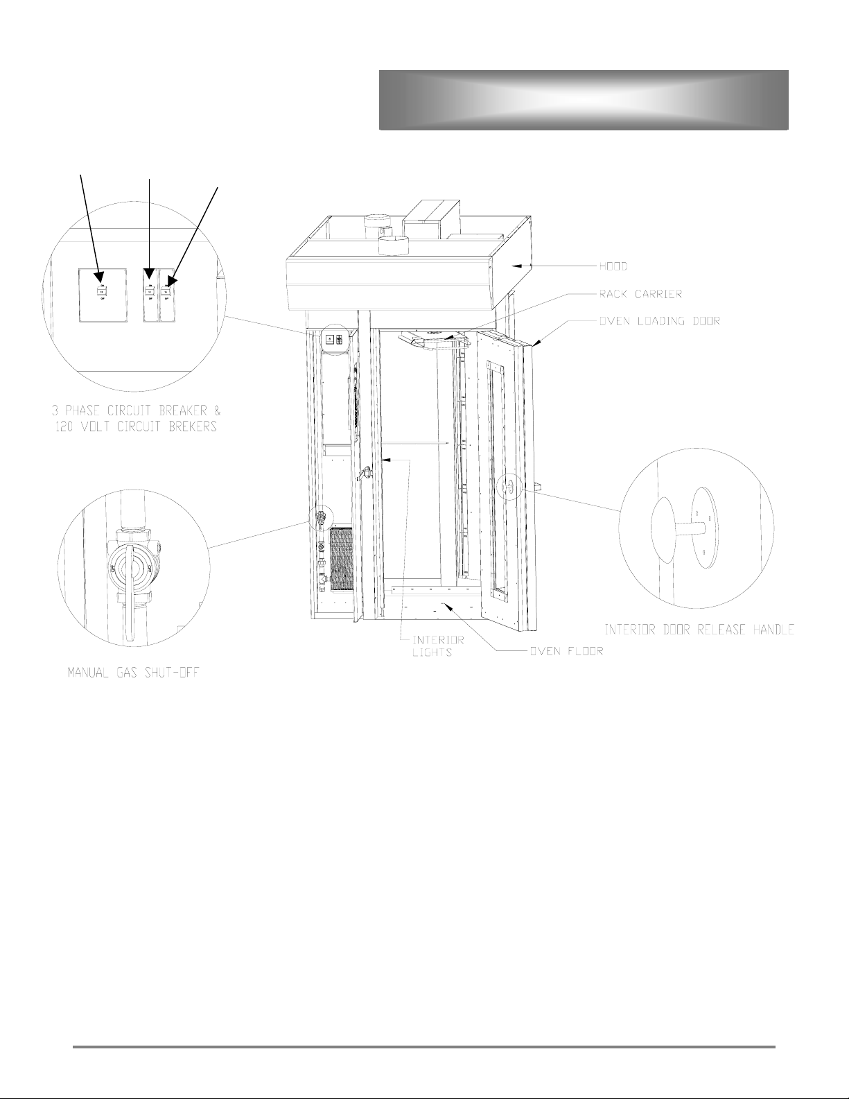
Hood
Steam and burner exhausts are discharged into the hood. Grease is channeled to and collected in a grease
cup for later removal.
Hood Exhaust
Cooking fumes and burner exhaust pass through a duct to the hood exhaust outlet. A customer-supplied
exhaust blower is required. The hood can be wired to the external device terminals in the service box.
This insures the hood is on whenever the oven is on. The “POWER” switch on the oven control panel
activates the blower. The blower must be running before the oven will operate. A factory installed airflow
switch disables heat until airflow exists.
Interior Door Release
This door release allows the door to be opened from inside the oven.
120V Circuit Breakers
Power to run the control panel and hood blower can be disconnected at these points. Switch to “OFF”,
when servicing oven or blower.
WARNING WIRES ENTERING THE DISCONNECT MAY STILL BE LIVE EVEN
Manual Gas Shutoff
Gas is supplied to the oven through this valve. This valve is typically left open, but needs to be closed
when servicing the oven. To close the valve, turn its handle to a horizontal position.
3-Phase Circuit Breaker
This disconnect provides short circuit protection for the circulation blower motor. Switch to “ OFF” when
servicing the oven.
WHEN THE SWITCH IS TURNED OFF. SWITCH THE MAIN
BREAKER AT THE WALL TO “OFF” WHEN SERVICING THE
OVEN
ETL File 3028821 8 Rev. #A2002
Circulation
Blower
EQUIPMENT DESCRIPTION CONT’D
Vent Blower Oven Controls
ETL File 3028821 9 Rev. #A2002

INSTALLATION INSTRUCTIONS
WARNING
Receiving the Oven
Upon receipt, check for freight damage, both visible and concealed. Visible damage should be noted on
the freight bill at the time of delivery and signed by the carrier's agent. Concealed loss or damage means
loss or damage, which does not become apparent until the merchandise has been unpacked. If concealed
loss or damage is discovered upon unpacking, make a written request for inspection by the carrier's agent
within 15 days of delivery. All packing material must be kept for inspection. Do not return damaged
merchandise to Lang Manufacturing Company. File your claim with the carrier.
Pre-Installation
Check the area where the oven is to be installed for the following:
• No electrical conduit or wires are to be under the floor of the oven.
• The oven must be mounted on a non-combustible surface. This includes the structure beneath the
floor.
• Ceiling height above the oven should be sufficient to allow servicing the lifter, vent and blower
motor assemblies. The maximum height needed for tilting the oven up is 105 inches.
• Clear access is needed to the roof or exterior of the facility for hood exhaust. Check local codes for
correct venting.
• Access is needed for an air-gap drain in the rear left corner of the oven.
• Adequate space is needed in front of the oven to load and unload racks. Racks are hot and need
space to cool.
• The oven needs air to operate. The hood exhaust will need at least 600-800 CFM of make-up air.
• Local and national codes will require an electrical shut-off within a reasonable distance to the oven.
• Local and National codes will require access to a manual Gas Shut-off.
• The door swing (46.0”) will need to be clear to allow adequate loading and unloading of the oven.
Check the space next to the oven and be sure it does not interfere with the door.
Un-Crating
TO REDUCE THE RISK OF FIRE, THE APPLIANCE IS TO BE
MOUNTED ON FLOORS OF NON-COMBUSTIBLE
CONSTRUCTION. SUCH CONSTRUCTION SHALL EXTEND A
MINIMUM OF 12-INCHES BEYOND THE EQUIPMENT ON ALL
SIDES.
The oven is shipped in two main pieces, not including hood.
Move the large oven crates into the room, near where it is to be installed. Allow clear access for a forklift
or lifting apparatus at the top end of the oven. The bottom end of the oven crate is beveled at the skids.
Check the crate for damage that may have occurred in shipping.
Remove crating materials and plastic wrap from the oven. Remove the heat exchanger vent duct from the
skid.
CAUTION
CAUTION THIS APPLIANCE, WHEN INSTALLED, MUST BE ELECTRICALLY
ETL File 3028821 10 Rev. #A2002
INSTALLATION MUST CONFORM WITH LOCAL CODES, OR IN
THE ABSENCE OF LOCAL CODES WITH THE NATIONAL FUEL
GAS CODE, ANSIZ223.11996.
GROUNDED IN ACCORDANCE WITH LOCAL CODES, OR IN THE
ABSENCE OF LOCAL CODES, WITH THE NATIONAL
ELECTRICAL CODE, ANSI/NFPA 70-1996.
INSTALLATION CONT’D
CAUTION FOR INSTALLATION IN CANADA THE INSTALLATION MUST BE
IN ACCORDANCE WITH CAN/CGA-B149.1&2 OF THE
INSTALLATION CODE, AND LOCAL CODES WHERE
APPLICABLE. ALL ELECTRIC WIRING MUST BE IN
ACCORDANCE WITH THE CURRENT CANADIAN ELECTRICAL
CODE, C22.1 PART 1. GROUNDING THIS APPLIANCE MUST
CONFORM TO CANADIAN ELECTRICAL CODE, CSA C22.2.
WARNING
INSTALLATION OF THE UNIT MUST BE DONE BY PERSONNEL
QUALIFIED TO WORK WITH ELECTRICITY AND PLUMBING
IMPROPER INSTALLATION CAN CAUSE INJURY TO
PERSONNEL AND /OR DAMAGE TO EQUIPMENT. UNIT MUST
BE INSTALLED N ACCORDANCE WITH ALL APPLICABLE
CODES.
WARNING
Raising:
Raise the oven to its vertical, upright position with the use of a forklift or other lifting device. Lower the
oven to the floor without dropping.
• Raise one end of each oven skid with a forklift until the oven is at 60° from horizontal. (If a forklift
is not available, use a pallet jack and successive stacks of pallets to raise the oven. DO NOT LIFT
THE OVEN BY HAND). Tilt the oven to the vertical position by hand from the raise position.
• Ease the oven to the floor and do not allow it to fall over. OVEN HALVES ARE UNSTABLE.
Assembly
Note: Nudge the halves with pry bars to move them. Do not force parts to fit.
• Move the erected oven halves to where the mating faces are 2-3 feet apart.
• Place the oven floor on the ground against the right wall of the oven and 6 inches forward of the rear
wall.
• Carefully raise the front edge of the right wall with a pry bar and slide the floor back until it touches
the back wall.
• Slide the right half of the oven toward the left half until the two mate together.
• Bolt the inner skin together at the rear, top and front header using 5/16-18 gimlet point screws
provided.
• Install ½-13x1 hex head bolts, nuts, and lock washers at the joint in the rear base, rear top frame and
header. Snug all bolts tight.
• Install the insulation provided at the center joint so that there are three layers and no voids.
• Slide the rear joint panel into the upper frame at the back of the oven and drop it into the lower
frame to close the back of the oven.
• Place the top insulation cover in place and secure it to the outer ceiling panel with the drill tip screws
provided.
• Raise the front header cover into position between the front jambs and slip it over the header frame
until it is flush with the front. Install two drill-tip screws through the top flange of the header cover.
Install #10x¾ stainless steel sheet metal screws through the bottom flange of the header cover. Use
care to keep the gasket in place.
• Install ¼-20x½” truss head stainless steel screws through the inner ceiling joint, inside the oven.
• Place the floor clamp strips around the inside walls of the oven. Install, using ¼-20x½” truss head
screws, washers and lock-washers, longer screws are provided for the overlapping joints at the
corners. Do not tighten these screws until the oven has been placed at its final location and leveled.
DO NOT ALLOW ANY PART OF YOUR BODY TO BE UNDER THE
OVEN DURING THE LIFTING PROCESS. KEEP EVERYONE
CLEAR FROM THE OVEN IF IT SHOULD FALL.
ETL File 3028821 11 Rev. #A2002

INSTALLATION CONT’D
Assembly Cont’d
Note: Lifter installation is not required on some ovens
• Place the lifter assembly on top to the oven without the rotator assembly. Center the lifter over the
rotator shaft housing with the lift motor to the rear of the oven.
• Install the rotator assembly through the lifter using care to locate the spring-steel clip between the
elevation micro-switches.
• Move the lifter assembly around until the rotator assembly is clear of the lifter frame and all moving
parts are free (this should be where the lifter is centered on the rotator shaft). Anchor the lifter
assembly in place with the fasteners provided.
• Remove the snap ring, square washer and shipping spacer from the rotator shaft.
• Remove the rack carrier from the bottom of the hood crate. Install the carrier on the rotator shaft
inside the oven using the snap ring provided. Install the four set-screws in the carrier-shaft collar.
Do not tighten yet, as this will allow the carrier to be aligned later.
• Install the end of the flex conduit from the blower motor into the lift frame.
• Uncoil the hi-limit switch from the hi-limit protector bracket and install in the side of the lifter frame
with the screws provided.
• Install the door micro-switch, (shipped wired to the lifter frame) at the door switch actuator bracket
above the loading door. Adjust the switch for 1/8” over travel. Adjust the switch actuator for
maximum travel.
• Connect the wires (34, 35 and 36) from the blower motor to the same wires in the lifter frame.
• Connect the wires (48 and 49) to the terminal at the high-limit switch.
• Connect the white plastic connector from the main harness to the white plastic connector on the
lifter harness.
• Check the location of all of the wires to ensure that they are free of sharp edges or moving parts.
• Install the transport wheel on the left jambs by raising the oven with the left front jackscrew, located
behind the control door, use the ¼-20 hex head bolts provided.
• Extend the transport wheel by adjusting the leveling jack screws in the rear.
ETL File 3028821 12 Rev. #A2002

INSTALLATION CONT’D
Setting
Remove the vinyl protective coating from all of the exterior surfaces.
Roll the oven into its final installed position. (You may wish to install the hood before locating the oven.)
Adjust the left front leveling screw until the weight is removed from the wheel assembly. Remove the
wheel assembly.
For right hand doors; adjust the rear leveling screws and the left front leveling screws until the left jamb
is level from left to right and front to back. Lock the left front adjusting screw in place.
Install the loading door.
• Remove the loading door from its crate.
• Stand the door up-right and move it into place with a hand truck.
• Raise the door hinges over the jamb hinges with the hand truck and lower in into place.
• Use care to avoid damaging the door seal.
Adjust the right front leveling screw until the gap at the top of the door opening is even all across. Check
the gap along the left side of the door. Recheck the level of the oven.
For left hand doors adjust the rear leveling screws and the right front leveling screws until the right jamb
is level from left to right and front to back. Lock the right front adjusting screw in place.
Install the loading door.
• Remove the loading door from its crate.
• Stand the door up-right and move it into place with a hand truck.
• Raise the door hinges over the jamb hinges with the hand truck and lower in into place.
• Use care to avoid damaging the door seal.
Adjust the left front leveling screw until the gap at the top of the door opening is even all across. Check
the gap along the right side of the door. Recheck the level of the oven.
Loosen the floor clamp screws around the perimeter of the oven floor.
Walk around the stainless floor until it is in full contact with the concrete floor. Retighten the floor clamp
screws.
Drill the floor with a 3/8” diameter drill to accept the concrete floor anchors.
• Mark the drill bit at 1-1/2” from the end with tape. Drill until the mark is at the top of the
stainless steel floor. Do not drill too deep.
• Clean the holes of concrete dust.
• If the oven is mounted on stone or ceramic tile, extend the holes and the anchors into the
concrete substrate.
Install the anchors in the holes and set in place with the anchor-setting tool. (Note: One good solid blow
is better than many little taps.)
Install the #¼-20 flat head screws in the anchors. Use the anchor washers at the holes in the middle of the
floor at the larger anchor holes. Additional screws have been provided in the event that a hole is drilled
too deep
Adjust the Loading door latch to ensure a good seal around the door. Do not over tighten the door.
Adjust the floor seal at the bottom of the door to insure a good seal to the floor.
ETL File 3028821 13 Rev. #A2002

INSTALLATION CONT’D
Check the level of the rack carrier shaft. Place an accurate level on the top of the carrier and rotate the carrier
to the four points of the compass. The level bubble should be in the same position relative to the carrier when
rotated. If not, remove the carrier and level the shaft.
• Loosen the four corner screws on the rotator shaft level adjusting plate on the under side of the
inner ceiling. Remove the two remaining screws.
• Move the shaft manually until the shaft is level in all four directions.
• Retighten the four corner screws.
Drill two new screw holes in the adjusting plate with a #7 drill bit and tap #¼-20. Install the two remaining
screws to lock the shaft level in place.
NOTICE Always ensure the grease filters supplied with the oven are
used. Replacement filters may be obtained from a Lang
representative.
NOTICE It is imperative that a mechanical exhauster is installed, and the
pressure sensitive switch provided is connected at the collar of
the hood. If a negative draw of 0.6” W.C. is not achieved, the
burner will not come on.
NOTICE No other exhaust systems may be connected to this system. Do
not try to vent or exhaust another appliance into this hood.
Installing the Hood
• Remove the hood from the hood crate. Place the body of the hood on the floor with the open side
down. Use cardboard or other protective material to avoid scratches.
• Remove all protective vinyl coatings and place the hood side support trim on each side of the hood
and screw to the front of the hood with (4) #1/4-20 stainless steel truss head machine screws and
spacer bushings. Install (4) #10-32 truss head stainless steel machine screws through the side support
trim and into the top of the hood.
• Attach the rear trim to the opposite end of the hood side support trim using (4) ¼-20 truss head
stainless steel machine screws.
• Place the combustion exhaust duct (shipped strapped to the oven skid) on the top of the heat
exchanger exhaust opening.
• Lift the hood and trim assembly and place it over the top of the oven so that the side and rear trim rest
on the top of the oven.
• Push the hood assembly toward the rear of the oven and align the vent exhaust opening and the
exhaust duct opening with the associated ducts on the oven.
• Attach the hood side support trim and the rear trim to the top of the oven with ¼-20 stainless steel
truss head machine screws.
• Attach the hood to the exhaust and vent ducts using #10 stainless steel sheet metal screws.
• Install the hood airflow sensor tube at the hood collar opening and at the airflow switch in the lifter
assembly located at the top of the oven. Double-check this connection for leaks or crimps in the tube
or hose.
• Install the hood deflector using #10-32 stainless steel round head machine screws at the back of the
deflector and #10-32 stainless steel truss head machine screws at three holes at the front edge of the
deflector.
• Place the three hood filters and the filler channel in the hood filter holder and onto the front lip of the
hood.
• Place the hood grease cup on the rear lip of the hood at the drain opening.
• Install the hood valance on the front of the hood.
ETL File 3028821 14 Rev. #A2002

INSTALLATION CONT’D
Connecting Utilities
NOTICE
• Connect gas to the oven at the gas connection pipe located at the upper left corner of the oven, above
the control cabinet. Be sure that there will be ample gas supply to operate the oven with 5” to 14”
W/C at all times.
• Connect the electrical service connection to the oven. Consult the data plate for specific current and
voltage ratings. Wire in compliance with local requirements and the National Electric Code.
• Connect water supply to the oven at the water solenoid valve at the top left corner of the oven. Water
supply must be between 20 and 80 psi at all times with a water flow of 9 gallons per minute. Provide
a water shut-off valve near the oven for servicing.
• Connect the drain to the oven. Water drained from the oven will reach temperatures near boiling.
The drain line must be provided with an air gap to prevent back siphoning.
Start-up:
• Remove all protective coatings from the oven surface, inside and out.
• Turn on the gas and water supplies to the oven. Check for leaks. Repair any leaks before proceeding.
• Confirm that all electrical connections are proper and all covers are in place. Confirm that the oven is
properly grounded.
• Turn on electrical power to the oven. Turn on all circuit breakers located in the electrical
compartment.
• Turn the power toggle switch into the “ON” position. The oven interior light should turn on and the
control display should light up.
• Close the loading door. The lifter and rack carrier should raise and begin to rotate. Open the door
and allow the carrier to stop rotating. Check the position of the alignment of the carrier to the door.
If the carrier needs adjustment, remove the chrome caps from the center channel on the rack carrier.
Loosen the four sets-crews that lock the carrier to the shaft. Rotate the carrier until it aligns with the
door and retighten the set-screws. Replace the chrome caps.
• Place an oven rack in the oven. Measure the spacing between the oven rack top channels and the rack
carrier. The space between the carrier lip and the top flange of the rack channel should be
approximately ¾”. Adjust the lifter micro-switch mount on the lifter body to compensate.
• Close the loading door and check the direction of rotation of the blower motor. The motor should
rotate counterclockwise when viewed from the top. Reverse L1 and L2 at the power supply side of
the motor circuit breaker.
• Heat the oven to 300°F. (Refer to the programming section of this manual for control operating
instructions.)
• Check the oven for gas leaks, excessive smoke, vibration and general operation.
Do not allow more than 14 inches pressure to be applied to the
gas valve at any time.
ETL File 3028821 15 Rev. #A2002

ETL File 3028821 16 REV.A2002
Roof top ventilator
Oven Controls
INSTALLATION CONT’D

WARNING
Power Failure:
Do not attempt to operate oven.
Turn the power to “OFF”.
Remove the product from the rack.
WARNING
Burner Failure:
1. Reset the burner:
a. Turn the power switch to “OFF”
b. Turn burner gas shut off valve’s to “OFF”
NOTICE
c. Turn burner gas shut-off valves to “ON”.
WHEN REMOVING THE RACK OR PRODUCT FROM THE RACK,
WHERE HOT MITTS TO AVOID SERIOUS BURNS.
DO NOT UNLOAD THE RACK FROM THE OVEN WHILE THE
CARRIER IS IN THE LIFT POSITION. LOADED RACKS CAN BE
EXTREMELY HEAVY.
Wait a minimum of five minutes before proceeding to the next
step.
EMERGENCY OPERATION
d. Turn Power switch to “ON”.
e. If necessary re-adjust the SET TEMP to the desired temperature.
2. Burner should now restart.
Product fire in the baking chamber
1. Turn power switch to “OFF”.
2. Wait until the fire has gone out before opening the door.
WARNING
DO NOT REMOVE A FLAMING PRODUCT FROM THE OVEN.
SEVERE BURNS AND PROPERTY DAMAGE CAN RESULT.
ETL File 3028821 17 Rev. #A2002

WARNING
GENERAL OPERATION
THIS LANG OVEN PRODUCES HUMIDITY THAT CAN CAUSE
THE INTERIOR FLOORING AND ADJACENT EXTERIOR
FLOORING TO BECOME SLIPPERY. USE EXTREME CAUTION
WHEN WALKING ON A WET OR DAMP FLOOR.
NOTICE
WARNING
NOTICE During the first few hours of operation you may notice a small
WARNING
Typical Operation
Preheat oven to desired temperature and allow oven to saturate for twenty minutes.
The steam generator absorbs heat and normalizes with the temperature in the cooking chamber.
Select a cooking program from the main menu of pre-saved programs. When selected, the temperature
setting changes to the correct temperature for the product.
Load a rack full of product into the oven, engaging the rack carrier automatically.
Close the oven door. The rack is lifted off of the floor, allowing it to rotate smoothly.
Press “START”
If a steam time has been set, water will flow into the steam generator and cascades through the labyrinth
of steel bars, converting the water into steam, which condenses on the food product.
When the steam cycle ends (less than 60 seconds,) the circulation blower will start and air will blow past
the heat exchanger and through the rack full of product.
The rotation of the rack insures that the product is cooked evenly throughout the rack. If venting is
desired, such as with breads, the vent cycle is selected when the program is started.
The vent opens for a limited time, allowing dry air to be drawn into the oven, forcing moist air out into the
hood.
The computer control manages all of the timing and temperature functions and sounds an alarm at the end
of the baking cycle.
Open the cooking chamber door and wait until the rack is rotated so that it is aligned with the door.
Release the latch at the top of the rack and remove the rack from the oven.
The ambient temperature outside the oven should not exceed
104° F (40° C). This includes the temperature of the air above
and around the oven.
IF BURNER DOES NOT LIGHT, TURN OFF POWER SWITCH,
MANUAL GAS SHUT-OFF VALVE AND BURNER GAS SHUT-OFF
VALVE. WAIT A MINIMUM OF 5 MINUTES, AND THEN TRY RELIGHTING GAS BURNER
amount of smoke coming off of the oven, and a faint odor from
the smoke. This is normal for a new oven and will disappear
after the first few hours of use.
WHEN THE LOADING DOOR IS OPENED, HOT AIR AND STEAM
ARE RELEASED FROM THE OVEN INTERIOR. TO AVOID BURNS
OPEN DOOR SLOWLY AND KEEP YOUR FACE AND HANDS
CLEAR OF THE OPENING. ALL INTERIOR SURFACES ARE
VERY HOT. DO NOT TOUCH ANYTHING WITHOUT OVEN MITTS.
ETL File 3028821 18 Rev. #A2002

GENERAL OPERATION CONT’D
Loading Procedures
Set the controls.
Open the door (slowly). Wait for the rack carrier to stop and lower.
Confirm that the rack stop is in the loading (LEADING FLAP UP) position.
Align the top channels of the oven rack with the rack carrier and push the rack past the rack stop.
Close the loading door. The rack carrier will automatically lift the rack and begin to rotate.
Begin baking by pressing START. A buzzer will sound when baking is completed.
Unloading Procedure
Press the STOP button or open the loading door to turn off the buzzer.
You can view your product through the window. If it appears ready, SLOWLY open the loading door
about 6 inches. Let steam and hot air escape from the opening (to be removed through the hood.)
Open the door completely. The rack carrier will come to a stop and the rack will lower.
USING OVEN MITTS, flip the rack stop to the unloading (LEADING FLAP DOWN) position.
Remove the rack from the rack carrier.
Close the loading door.
Shut Down Procedure
1. Turn the power switch to the “OFF”“ position.
2. For lengthy shutdown periods or maintenance, turn power off at the120-Volt, 208/240-volt circuit
breakers.
3. Turn off the gas supply by setting the Manual Gas Supply Shutoff valves to “OFF”.
4. Switch the oven disconnect to “OFF”.
ETL File 3028821 19 Rev. #A2002

Manual Operation:
To operate the control without the use of pre-set programs, follow the instructions listed below.
1. Turn the oven on by pressing the “Power” button. The oven will automatically start preheating
to the last set temperature.
2. Press either the up or down arrows until manual program is displayed.
3. Press the “Program” button; this will display the events window where time, temp, steam, vent,
and pulse can be set.
4. Press the “Select” button to move between functions and the up and down arrows to change the
settings.
5. Set the desired tier cooking time by using the up or down arrows and then the “Select” button, to
advance to the temperature setting.
6. Enter the desired temperature using the up or down arrows and then the “Select” button, to
advance to the Steam setting.
7. If you desire to steam in the first tier enter the time you would like to steam for, using the up or
down arrows, for a maximum of 60 seconds. Press the “Select” button; to advance to the Vent
setting.
8. If the vent is to be open for a period of time there are two methods to do this. Either press the
“Vent” button during the count down cycle when the vent is to be open and then press it again to
close it, or the other method requires that a separate tier be set up. To do this press the “Select”
button until the time for the second tier is highlighted, using the up or down arrow keys select a
time that the vent is to be open. Press the “Select” button until the Vent is highlighted. Press the
up or down arrows until “o” is displayed. This will open the vent for the total time set for tier.
9. If the vent does not need to be opened press the “Select” button until BL is highlighted, then
using the up or down arrows to select either “—“ (fan on), “d” (fan delay), or “p” (pulse fan). If
“—“ is selected then the fan will run continuously through the tier, if “d” is selected then the fan
will be off for the duration of the cook tier, and if “p” is selected then the computer will ask for a
on and a off time and pulse the fan for the duration of the tier.
10. Once the program has been set load the oven and select “Run”
11. The oven will run the program and then beep continuously.
PROGRAMMING
ETL File 3028821 20 Rev. #A2002

PROGRAMMING CONT’D
Preset Programs
The oven has the capacity to program and save up to 36 programs. These programs are imputed in much
the same way as the normal operation program except they will be saved and stay even after the computer
has been turned off.
1. Using the up or down arrows scroll to an open recipe and press the “Program” button. This will
2. The time setting for the first tier will be highlighted. Using the up or down arrow keys select the
3. Once the time has been set press the “Select” button this will highlight the temp function. Using
4. Once the temp has been set press the “Select” button, this will highlight the steam function (the
5. If no steam is required or the steam time has been set press “Select” button, this will highlight
6. If no vent is required press the “Select” button, this will highlight the BL. Using the up or down
7. Once the tiers have been set up press the save button. This will put you back to the name and
8. Press the arrow under “Name” and use the up or down arrows to locate the correct letter and
9. Once the name is in the way it should appear, press the up or down arrow to scroll to another
Recommended Program Settings:
open the event screen, where 5 tiers are displayed.
desired time.
the up or down arrows to select the temp.
time entered here will not be in addition to the already set time). Using the up or down arrow
keys select a steam time up to 30 seconds.
the vent function. If the vent is to be open a separate tier must be used, where the total tier time
is the time the vent will be open. Press the up or down arrow keys until “o” is displayed, this
will open the vent for the total tier time.
arrows select either “—“ (fan on), “d” (fan delay), or “p” (pulse fan). If “—“ is selected then the
fan will run continuously through the tier, if “d” is selected then the fan will be off for the
duration of the cook tier, and if “p” is selected then the computer will ask for a on and a off time
and pulse the fan for the duration of the tier.
icon screen. Press the arrow under “Icon” and the up and down arrows to select an icon.
select to save the letter.
recipe or “Select” to run the new recipe.
Sugar Cookies: 345 Degrees for 12 minutes, no steam, no vent, no fan delay.
Step 1 2 3 4 5
Time
Temperature
Steam
Vent
BL --
1. Turn oven on and select a recipe, press the “Program” button.
2. Set Time to 12 minutes.
3. Press “Select” and set the temp to 345°F
4. Press the “Save” button and select a icon and a name.
ETL File 3028821 21 Rev. #A2002
12:00
345°F
:00
--

PROGRAMMING CONT’D
Muffins: 400 Degrees for 18 minutes, no steam, 3 minutes fan delay, no vent
Step 1 2 3 4 5
Time
Temperature
Steam
Vent
BL d
1. Turn oven on and select a recipe, press the “Program” button.
2. Set the time to 3 minutes.
3. Press the “Select” button and set the temp to 400°F.
4. Press the “Select” button until the BL function is highlighted. Press the up or down arrow until “d” is
displayed.
5. Press the “Select” button until the tier 2-time function is highlighted. Select a time fro 15 minutes.
6. Press the “Select” button and set the temp to 400°F.
5. Press the “Save” button and select a icon and a name.
Croissants: 375 degrees for 10 to 18 minutes (depending on size), no steam, no fan delay, no vent.
Step 1 2 3 4 5
Time
Temperature
Steam
Vent
BL --
3:00 15:00
400°F 400°F
:00
--
12:00
375°F
:00
--
1. Turn the oven on and select a recipe, press the “Program” button.
2. Set Time to 12 minutes.
3. Press “Select” and set the temp to 375°F
4. Press the “Save” button and select a icon and a name.
Roast Beef: 350 degrees for 3 hours, 5 seconds of steam every 30 minutes, no vent no fan delay.
Step 1 2 3 4 5
Time
Temperature
Steam
Vent
BL -- -- -- -- --
1. Turn the oven on and select a recipe, press the “Program” button.
2. Press the “Select” button and set the time for 36:00 minutes
3. Press the “Select” button until temp is highlighted, set the temperature to 350°F.
4. Press the “Select” button and set the steam time for 5 seconds.
5. Press the “Select” button until the time is highlighted for the second tier. Set the time for 30 minutes.
6. Press the “Select” button and set the temperature to 350°F
7. Press the “Select” button and set the bake time to 30 minutes.
8. Press the “Save” button and select an icon and a name.
36:00 36:00 36:00 36:00 36:00
350°F 350°F 350°F 350°F 350°F
:05 :05 :05 :05 :05
-- -- -- -- --
ETL File 3028821 22 Rev. #A2002

PROGRAMMING CONT’D
French Bread: 425 degrees for 25 minutes, 25 seconds of steam, 1 minute of fan delay, 1 minute of vent,
additional vent at the last minute.
Step 1 2 3 4 5
Time
Temperature
Steam
Vent
BL -- d------
1. Turn the oven on and select a recipe, press the “Program” button.
2. Press the “Select” button and enter a time of: 25 seconds
3. Press the “Select” button until temp is highlighted, set the temperature to 425°F.
4. Press the “Select” button and set the steam time for: 25 seconds.
5. Press the “Select” button until the time is highlighted for the second tier. Set the time for: 45 seconds.
6. Press the “Select” button and set the temperature to 425°F
7. Press the “Select” button until the BL function is highlighted. Set the BL for “d”.
8. Press the “Select” button until the time function is highlighted for the third tier. Set the time for 1 minute.
9. Press the “Select” button and set the temperature to 425°F.
10. Press the “Select” button until the vent function is highlighted. Set the vent to “o”.
11. Press the “Select” button until the time function is highlighted for the fourth tier. Set the time for 22 minutes.
12. Press the “Select” button and set the temperature to 425°F.
13. Press the “Select” button until the time function is highlighted for the fifth tier. Set the time for 1 minute.
14. Press the “Select” button and set the temperature to 425°F.
15. Press the “Select” button until the vent function is highlighted. Set the vent to “o”
16. Press the “Save” button and select a icon and a name.
00:25 : 45 1:00 22:00 1:00
425°F 425°F 425°F 425°F 425°F
: 25 :00 :00 :00 :00
-- -- O -- O
ETL File 3028821 23 Rev. #A2002

GENERAL MAINTENANCE
NOTICE
NOTICE
Preventative Maint.
1. GAS OVENS ONLY: Inspect, adjust and service the oven burner according to the instructions in
this manual.
2. Verify hood exhaust air-pressure switch is operating properly.
3. Inspect heat exchanger for cracks, openings or excessive corrosion.
4. Check loading door handle & striker adjustment and verify the mounting screws are tight.
5. Check interior loading door release for proper operation.
6. Clean hood filters with soap and water.
7. Check and tighten any loose screws, on both the interior and exterior of the oven.
8. Check the rack lift assembly for proper operation. Adjust limit switch as needed.
9. Check rotator chain adjustment and its alignment on the rack rotator assembly. Lubricate the drive
chain if needed.
10. Grease bearings in circulation blower motor. Apply two stokes into each of the two fittings on motor.
11. Clean flour and dust that may have accumulated on top of the circulation blower motor.
12. Check steam system for proper operation and drainage.
13. Clean steam systems supply tubes nozzles and drain pan, if needed.
14. Check vent for proper operation.
15. Check loading door switch actuator for proper adjustment.
16. Check the loading door seal and door sweep condition.
17. Check control panel for proper operation.
18. Check the evenness of bake. Confirm with the oven user and verify that all pans and all locations are
being browned equally.
NOTICE
Service on this, or any other, LANG appliance must be
performed by qualified personnel only. Consult your authorized
service station directory or call the factory at 1-800-224-LANG
(5264) or WWW. LANGWORLD.COM for the service station
nearest you.
To maintain optimum safety and performance for LANG Rack
oven models LRO-1G & LRO-2G, it is recommended that a
program of scheduled periodic maintenance be implemented.
It’s sole responsibility of the user to establish, schedule and
enforce such a program. Although the actual service interval will
vary depending on the environment in which the equipment is
operating, it is recommended the following be done by a LANG
authorized service agency at least every 6 months.
For periodic maintenance and repairs, electrical diagrams are
included in this manual and with the oven (on the back of the
control door).
ETL File 3028821 24 Rev. #A2002

GENERAL MAINTENANCE CONT’D
WARNING
Motor Reset
One of the overload protectors may require resetting if the circulation blower does not start, quits or if the
rack does not lift and rotate with the loading door closed. This is done automatically-nothing has to be
done by the operator. After a few minutes, the oven should reset and normal operation should resume. If
it has not after fifteen minutes, call for service.
NOTICE
SINCE RESETS FOR THE CIRCULATION BLOWER MOTOR AND
THE LIFTER MOTOR / ROTATOR MOTOR ARE AUTOMATIC, ALL
POWER TO THE OVEN MUST BE TURNED OFF BEFORE
SERVICING.
If shutter settings are to be adjusted differently than the
recommended factory settings, the best results will be obtained
if you (A) start with the factory settings, (B) close shutters to
lighten a product in a given area- do not open shutters to darken
a product, (C) do not move a shutter more than 1/32” or 1mm
(see step gauge illustration) at any one time, (D) be sure all
settings for left hand shutters match those for right hand
shutters, and (E) do not adjust more than two shutters per side
per time (four shutters total).
Uneven Baking
If side-to-center bake is uneven, check the angles of the shutters to determine if they match the factory
settings. (The angle shutters are short angles located on the pressure panel. There are 12 shutters per
oven.) The angles of the shutters must be checked while oven is cool.
CAUTION
If an uneven bake problem cannot be corrected by the procedure just described, check the following:
• Voltage at blower. If voltage varies too much or if voltage is too low, a bad bake may occur.
• Gas pressure when the gas burner is on.
• The oven suction panel. Release paper sucked into the panel will reduce airflow.
• Blower rotation. If blower rotation is incorrect, it will cause an uneven bake, and severe damage to
heat exchanger.
• Your product. Contact your supplier to determine if there has been any change in raw or mixed
product.
• Your product. Closely monitor the water content of the raw product.
• If the problem still cannot be corrected, call a factory authorized service company.
IF BLOWER ROTATION IS INCORRECT, IT WILL CAUSE SEVERE
DAMAGE TO HEAT EXCHANGER
ETL File 3028821 25 Rev. #A2002

GENERAL MAINTENANCE CONT’D
STEP GAUGE ILLUSTRATION
ETL File 3028821 26 Rev. #A2002

SAFETY CONSIDERATIONS
Your LANG oven was manufactured to rigid standards. The oven is ETL listed as a unit, and meets safety
standards.
A) The responsibility of the manufacturer
recommendations for the operation and maintenance of the subject units.
B) Trained, qualified personnel must perform all operation, maintenance and repair of the subject units.
It is the responsibility of the owner/operator
C) A regular periodic program of cleaning, inspection and maintenance must be established and
comprehensive maintenance records maintained. It is the sole responsibility of the user
schedule and enforce the frequency and scope of these programs in keeping with recommended
practice and with due consideration given to actual operating conditions.
D) The units must be operated within limits, which will not exceed the working limits of any component.
is to supply suitable, comprehensive instructions and
to insure this happens.
to establish,
ETL File 3028821 27 Rev. #A2002

ETL File 3028821 28 REV.A2002
ITMEM # QTY. PART # DESCRIPTION
1A 28 80400-30 BURNER ORIFICE, #52 DRILL, NG
1B 28 80400-29 BURNER ORIFICE, #61 DRILL, LP
1C 28 80400-34 BURNER ORIFICE, #578 DRILL, LP (FOR INSTALLATIONS BETWEEN 3000 & 6000 FEET)
2 28 80002-14 BURNER
3 1 80201-29 PILOT BURNER WITH SPARK ELECTRODE
PARTS LIST

ETL File 3028821 29 REV.A2002
ITMEM # QTY. PART # DESCRIPTION
1 1 80300-03 120-VOLT SPARK MODULE
2 1 150-621 FLAME SENSOR MOUNT
3 1 80506-01 PILOT FLAME SWITCH
PARTS LIST

PARTS LIST CONT’D
ITEM# QTY PART # DESCRIPTION
1 1 70404-03 GAUGE 0-100 PSI
2 1 70404-05 REGULATOR, WATER 10 PSI
3 1 70302-39 BRASS PIPE NIPPLE, ½ NPT
4 1 70101-102 BRASS TEE, ½ NPT
5 1 70302-39 BRASS PIPE NIPPLE, ½ NPT
6 1 70403-03 SOLENOID VALVE, WATER
7 1 70307-08 PIPE REDUCER, ½ X 3/8
8 1 41100-33 TEMPERATURE SENSING PROBE
9 1 70101-100 COMPRESSION FITTING FOR PROBE
10 1 30301-16 MICRO SWITCH DOOR
11 1 70701-92 BRASS FITTING-PACKING FOR STAT
12 1 70307-04 PIPE REDUCER, ½ X 1/4
ETL File 3028821 30 Rev. #A2002

A
Y
PARTS LIST CONT’D
ITMEM # QTY. PART # DESCRIPTION
1 1 50800-103 MAIN HANDLE ASSEMBLY
2 1 160-106 SWEEPER
3 1 150-786 FEMALE HINGE ASSEMBLY, LOWER
4 1 150-786-1 FEMALE HINGE ASSEMBLY, UPPER
5 1 150-703 ESCAPE HANDLE ASSEMBLY
6 1 71301-19 WINDOW
SSEMBL
ETL File 3028821 31 Rev. #A2002

PARTS LIST CONT’D
Item No. Qty. Part No. Description
1 4 30500-16 TERMINAL BLOCK
2 1 31800-12 3 PHASE, 15 AMP CIRCUIT BREAKER
3 2 150-657 DINRAIL, 6”
4 1 30700-15 CONTACTOR, CIRCULATION BLOWER
5 1 30707-03 OVERLOAD, CIRCULATION BLOWER
6 1 31600-12 LIGHT BALLAST
7 5 30701-05 RELAY, 24-VOLT
8 1 31400-27 TRANSFORMER, 120/24-12 VOLT
9 1 31400-31 TRANSFORMER
10 1 30707-01 OVERLOAD, LIFT ROTATE ASSEMBLY
11 1 31200-08 GROUND LUG
12 1 60301-142 PANEL LABEL
13 1 40102-54 CIRCUIT BOARD, MICROPROCESSOR
ETL File 3028821 32 Rev. #A2002

PARTS LIST CONT’D
ITMEM # QTY. PART # DESCRIPTION
1 1 30200-57 LINEAR ACTUATOR
2 1 50803-004 LIFTER PIN
3 1 150-138 FORK CLIP TEFLON
4 1 150-137 FORK CLIP S/S
5 1 150-135 LIFTER WASHER
6 1 30301-02 MICRO-SWITCH
7 1 30308-05 AIR SWITCH
8 1 30401-26 OVER-TEMP THERMOSTAT
9 1 150-179 MICRO SWITCH BRACKET
10 1 150-158 MICRO SWITCH ACTUATOR
ETL File 3028821 33 Rev. #A2002

PARTS LIST CONT’D
ITMEM # QTY. PART # DESCRIPTION
1 2 50803-003 DRIVE BUSHING
2 1 70200-11 BUSHING
3 1 70200-12 WASHER
4 1 73000-06 DRIVE SPROCKET
5 1 73500-05 MOTOR SPROCKET
6 1 40704-06 MOTOR CAPACITOR
7 1 71500-12 ROTATION MOTOR FAN
8 1 30200-56 DRIVE MOTOR
9 1 30301-15 ROTATOR MICRO SWITCH
10 1 50803-002 DRIVE COLLAR
11 1 70200-14 WASHER FRICTION THRUST
12 1 70200-13 BUSHING, CHAIN GEAR
ETL File 3028821 34 Rev. #A2002

PARTS LIST CONT’D
ITEM# QTY. PART# DESCRIPTION
1 1 30200-59 MAIN BLOWER MOTOR
2 1 71500-14 MAIN BLOWER HEAT SINK
3 1 20601-07 RETAINING SNAP RING
4 1 150-368 BUSHING
5 1 71500-13 MAIN BLOWER WHEEL
ETL File 3028821 35 Rev. #A2002

ITEM # QTY. PART # DESCRIPTION
1 1 150-135 LIGHT HOUSING BACK
2 2 31602-07 LIGHT SOCKET
3 1 31600-13 4 FOOT FLUORESCENT BULB
4 2 20201-09 5/16” WASHER
5 1 50803-009 DAMPER ROD
6 1 150-790 DAMPER FORK
7 1 150-353 DAMPER ARM
8 1 150-349 DAMPER MOUNT
9 1 70403-04 120-VOLT DAMPER SOLENOID
10 1 80505-14 GAS VALVE, NG OR LP
PARTS LIST CONT’D
ETL File 3028821 36 Rev. #A2002

WIRING DIAGRAM
CB1 CB2
LINE
LINE
3
120 VAC
TB1
To Vent Motor
5
TB2
NGND
7
2 2
4
6
TR2
3
2
44
TR1-1
1
J 1
13
2
J6
2
2
RTD
45
208/240 VAC
87
44
65
44
43
44
44
44
44
44
J4
J4
50
J4
4
3
J5
21
J4
MR5
59
46
MR1
P1-5
HL1
48
OL1
P1-6
52
MR6
53
6
12 13 14
OL2
51
MR4
17
45
AS1
57
45
P2-4
P2-5
49
MR2
SV1
SA1
60
57
P2-1 P2-2
MS2
CA1
MS3
15
UP
16
DN
18
MS4
Heat
Circuit
45
45
28
61
12
J5
MR3
58
RED
19
M2
M
BLK
BLK
M
RED
M3
4547
45
56
P2-3
2
2
MS1
45
45
45
L1 L2 L3
CB3
31 32 33
34 35 36
M
M1
L1 - T1,T7
L2 - T2,T8
L3 - T3,T9
(T4,T5,T6)
1 - 21 120 Volt
31 - 36 208/240 Volt
41 - 61 24 Volt
Shielded 5 Volt DC
Cable
J1 - J6 Computer
P1 [1 - 9] Plug, Control
P2 [1 - 9] Plug, Lift -
Inputs and
Outputs
Component
Mount
Rotate
Assembly
IL1
20 21
6
2
BA1
ETL File 3028821 37 REV.A2002

ETL File 3028821 38 REV.A2002
2 6
115
VAC
NGL
Spark
Module
HV
Sense
Spark
Combination
Valve
Off
On
12
34
Pilot
Front
Burner Assembly
CV1
Flame
Switch
GAS CIRCUIT
45
44
49

WARRANTY
Lang Manufacturing Limited
Warranty to Commercial
Purchasers*
(Domestic U.S., Hawaii, &
Canadian Sales only.)
Lang Manufacturing Equipment (“Lang Equipment”)
has been skillfully manufactured, carefully inspected
and packaged to meet rigid standards of excellence.
Lang warrants its Equipment to be free from defects
in material and workmanship for (12) twelve
consecutive months, with the following conditions and
subject to the following limitations.
I. This parts and labor warranty is limited to Lang
Equipment sold to the original commercial
purchaser/users (but not original equipment
manufacturers), at its original place of installation,
in the continental United States, Hawaii and
Canada.
Quartz elements are warranted for ninety-days
(90) from the date of installation.
II. Damage during shipment is to be reported to
the carrier, is not covered under this warranty,
and is the sole responsibility of
purchaser/user.
III. Lang, or an authorized service representative,
will repair or replace, at Lang’s sole election,
and Lang Equipment, including but not limited
to, safety valves, gas and electric
components, found to be defective during the
warranty period. As to warranty service in the
territory described above, Lang will absorb
labor and portal to portal transportation costs
(time & mileage) for the first (12) twelve
months from the date of installation or
eighteen (18) months from date of shipment
from Lang Manufacturing, which ever comes
first.
IV. This warranty does not cover routine general
maintenance, periodic adjustments, as specified in
operating instructions or manuals, and consumable
parts such as quartz elements, or labor costs
incurred for removal of adjacent equipment or
objects to gain access to Lang Equipment. This
warranty does not cover defects caused by improper
installation, abuse, careless operation, or improper
maintenance of equipment.
V. THIS WARRANTY IS EXCLUSIVE AND IS IN LIEU
OF ALL OTHER WARRANTIES, EXPRESSED OR
IMPLIED, INCLUDING ANY IMPLIED WARRANTY
OF MERCHANTABILITY OR FITNESS FOR A
PARTICULAR PURPOSE, EACH OF WHICH IS
HEREBY EXPRESSLY DISCLAIMED. THE
REMEDIES DESCRIBED ABOVE ARE EXCLUSIVE
AND IN NO EVENT SHALL LANG BE LIABLE FOR
SPECIAL, CONSEQUENTIAL OR INCIDENTAL
DAMAGES FOR THE BREACH OR DELAY IN
PERFORMANCE OF THIS WARRANTY.
VI. Lang Equipment is for commercial use only. If sold
as a component of another (OEM) manufacturer’s
equipment, or if used as a consumer product, such
Equipment is sold AS IS and without any warranty.
ETL File 3028821 39 Rev. #A2002
 Loading...