

Page 1
Installation
Operation
Maintenance
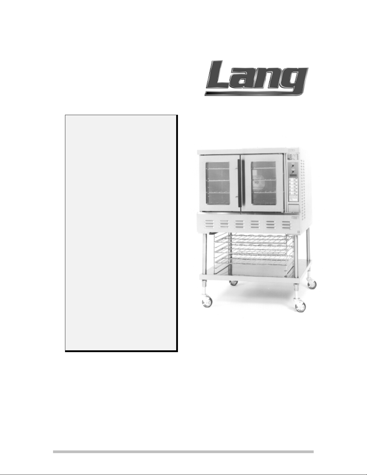
Model: GCCO-C
Lang Manufacturing Company 10 Sunnen Drive St. Louis, MO 63143
Part Number 60800-13 Rev. C Phone: 314-687-6315 Fax: 314-781-2714 September 1, 2011
Page 2

INSTALLATION INSTRUCTIONS
IMPORTANT IMPORTANT IMPORTANT
Post in a prominent location, a set of instructions to be followed in the event the user smell gas.
Obtain these instructions from your local gas supplier.
FOR YOUR SAFETY
Do not store or use gasoline or other flammable
vapors and liquids in the vicinity of this or any
other gas appliance.
In the event a gas odor is detected, shut down
units at the main shut-off valve and contact the
local gas company or supplier for service.
Installation, startup and adjustments of this appliance should be accomplished by personnel
qualified to install gas equipment.
Retain this manual for future reference.
Lang Manufacturing Company 10 Sunnen Drive St. Louis, MO 63143
Part Number 60800-13 Rev. C Phone: 314-678-6315 Fax: 314-781-2714 September 1, 2011
Page 3

TABLE OF CONTENTS
TABLE OF CONTENTS ..................................................................................................................0
INSTALLATION ..............................................................................................................................1
RECEIVING THE OVEN ...........................................................................................................1
DATA PLATE INFORMATION ................................................................................................1
VENTILATION AND CLEARANCES ......................................................................................1
LEGS ............................................................................................................................................1
STACKING THE OVENS ..........................................................................................................2
FLU EXTENSION .......................................................................................................................2
GAS CONNECTION ...................................................................................................................2
ELECTRICAL CONNECTION ..................................................................................................2
INITIAL START UP ...................................................................................................................3
OPERATION .....................................................................................................................................4
GENERAL ...................................................................................................................................4
CONTROL PANEL .....................................................................................................................4
STATUS SCREEN ......................................................................................................................5
TYPICAL OPERATION .............................................................................................................5
MANUAL BACK-UP ..................................................................................................................6
TEMPERATURE RECALL BUTTON .......................................................................................7
READ/CLEAR BUTTON ...........................................................................................................7
MANUAL BACK-UP ..................................................................................................................7
MAINTENANCE ..............................................................................................................................8
CLEANING .................................................................................................................................8
DOOR CHAIN ADJUSTMENT..................................................................................................8
SERVICE ...........................................................................................................................................9
CALIBRATION ...........................................................................................................................9
CONTROL PANEL REMOVAL ................................................................................................9
MOTOR REMOVAL ..................................................................................................................9
SAFETY THERMOSTAT REMOVAL ......................................................................................9
PARTS ................................................................................................................................................11
CONTROL PANEL LAYOUT....................................................................................................11
PARTS LIST ................................................................................................................................12
WIRING DIAGRAM ........................................................................................................................13
WARRANTY .....................................................................................................................................14
Lang Manufacturing Company 10 Sunnen Drive St. Louis, MO 63143
Part Number 60800-13 Rev. C Phone: 314-678-6315 Fax: 314-781-2714 September 1, 2011
Page 4

INSTALLATION
RECEIVING THE OVEN
Upon receipt of the appliance, check for freight
damage both visible and concealed. Visible
damage should be noted on the freight bill at the
time of delivery and signed by the carrier's
agent. Concealed loss or damage means loss or
damage which does not become apparent until
the merchandise has been unpacked. If
concealed loss or damage is discovered, make a
written request for inspection by the carrier's
agent within 15 days of delivery. All packing
material should be kept for inspection. Do not
return damaged merchandise to Lang
Manufacturing Company. File your claim
with the carrier.
Uncrate the appliance as near its intended
location as practical. The crating will help
protect the unit from the physical damage
normally associated with moving it through
hallways and doorways.
DATA PLATE INFORMATION
A data plate is located inside the control
compartment above the control. Look through
the perforated opening above the control panel
and to the left to view the data plate. A
flashlight may be helpful.
The oven voltage, wattage, serial number, wire
size and clearance specifications are on the data
plate.
This information should be carefully read and
understood before proceeding with the
installation.
VENTILATION AND
CLEARANCES
Standard minimum clearance from combustible
construction is as follows:
2 inches from sides
4 inches from back
6 inches from floor
These ovens may be set directly, without legs, on
a curbed base or non combustible floor.
If the oven is set without legs on a non
combustible floor or a curbed base, maintain a 4
inch back clearance.
If the oven is set directly against a non
combustible back wall, maintain a 6 inch
clearance to the floor.
Do not install the oven closer than 3 inches from
another oven on the right hand side (control
panel side).
Do not install the oven closer than 12 inches
from an uncontrolled heat source (char broiler
etc.) on the right side.
Keep the appliance area free and clear of
combustible material and do not obstruct the
flow of combustion or ventilation air.
The installation of any components such as a
vent hood, grease extractors, and/or fire
extinguisher systems, must conform to the their
applicable nationally recognized installation
standards.
LEGS
Legs are available for both the single and double
deck installations. Single deck installations
require a 27 inch leg. Double deck installations
require a 6 inch leg or caster.
To install the 27 inch legs, place cardboard on
the floor and gently tip the oven onto its back.
Fasten two legs to the oven's front corners using
the four 5/16 diameter bolts provided in the leg
kit. Lift the oven onto the front legs and block
the back of the oven using one of the 27 inch
legs set upside down in the center rear of the
oven body. Install the last 27 inch leg onto the
oven body on the control side rear. Gently lift
the oven rear and remove the leg set to support
the oven center and install it on the last rear
corner.
To install the 6 inch legs or casters, attach the
leg/caster to the supports supplied with the oven
(located inside the oven cavity in a box labeled
Leg Pads). Follow the instructions in the Leg
Pad box to attach the pad to the oven.
The adjustable feet on the bottom of each leg
may be screwed in or out as necessary to level
the oven.
1
Page 5
A spirit level, placed on an oven rack, will assist
in leveling the oven.
STACKING THE OVENS
Remove all of the plug buttons from the top of
the lower oven.
Remove the stacking kit from the oven
compartment.
All gas connections must be in accordance with
local codes and comply with the National Fuel
Gas Code ANSI Z223.1 latest edition.
A internal gas pressure regulator is located
inside the control compartment.
Gas must be delivered to the appliance regulator
at less than 1/2 pound of pressure and less than
1/2 inch water column pressure drop.
Tip the top oven backwards and install two 3/8
diameter Allen Head bolts (found in the stacking
kit) into the two front leg holes that match the
holes in the top of the lower oven. Install the
Allen Head bolts with the heads of the bolts
pointing away from the oven.
Lift the top oven and gently set on top of the
lower so that the heads of the bolts ne st into the
holes in the top of the lower oven.
FLU EXTENSION
A flu extension must be installed on the lower
oven of a stacked set. The extension attaches to
the flu opening of the lower oven and directs the
flu products into the flu opening of the upper
oven. This extension must be installed.
The ovens may now be set into position. Be
careful if sliding the ovens, they are not designed
to slide over cracks or obstructions in the floor.
GAS CONNECTION
DANGER
AS WITH ANY GAS APPLIANCE INSTALLED ON CASTERS,
ANY LANG GAS GRIDDLE, GAS CLAMSHELL®, OR GAS
CONVECTION OVEN ON CASTERS MUST BE INSTALLED
WITH THE FOLLOWING:
A CONNECTOR THAT COMPLIES WITH THE STANDARD
FOR CONNECTORS FOR MOVABLE GAS APPLIANCES,
ANSI Z21.69 LATEST EDITION.
AND
A QUICK DISCONNECT THAT COMPLIES WITH THE
STANDARD FOR QUICK DISCONNECT DEVICES FOR USE
WITH GAS FUEL, ANSI Z21.41 LATEST EDITION.
AND
A TETHER OR OTHER MEANS TO LIMIT APPLIANCE
MOVEMENT WITHOUT RELIANCE ON THE GAS SUPPLY
PIPING. SECURELY ATTACH THE TETHER TO THE
EYEBOLT PROVIDED AT THE REAR OF THE APPLIANCE.
FAILURE TO INSTALL THESE PARTS CAN LEAD TO
LEAKAGE OF GAS AND RESULTING FIRE, EXPLOSION,
PERSONAL INJURY AND DEATH.
This appliance is manufactured for use with the
type of gas indicated on the data plate. Contact
the factory if the gas type does not match that
which is on the data plate.
The internal regulator is preset at the factory,
however, due to gas pressure variations from
area to area, adjust the regulator to provide the
manifold pressure indicated on the data plate.
This should be 5 inches water column for natural
gas and 10 inch water column for propane. A
1/8 inch NPT tap is provided on the main
manifold for checking regulator pressure.
Access the main manifold by removing the trim
piece below the oven doors.
When replacing the 1/8 inch plug in the main
manifold a joint sealant that is resistant to the
action of liquid petroleum gas must be used.
The supply piping must be of sufficient size to
provide 55,000 BTU/hr per oven. A 1/2 inch
NPT connection is provided at the rear of the
oven directly behind the control compartment.
Connect each oven separately.
A gas shut off valve must be installed to the
oven(s) and located in an accessible area.
This appliance and its individual shutoff valve
must be disconnected from the gas supply piping
system during any pressure testing of that system
at test pressures in excess of 1/2 PSGI (3.45
kPA) and the appliance must be isolated from
the gas supply piping system by closing its
individual manual shutoff valve during any
pressure testing of the gas supply system at test
pressures equal to or less than 1/2 PSIG (3.45
kPA).
Test for gas leaks. Use a commercial leak
detector or a soap and water solution.
WARNING
DO NOT USE AN OPEN FLAME TO TEST
FOR GAS LEAKS.
ELECTRICAL CONNECTION
WARNING
ELECTRICAL GROUNDING
INSTRUCTIONS
2
Page 6

THIS APPLIANCE IS EQUIPPED WITH A 3PRONG (GROUNDING) PLUG FOR YOUR
PROTECTION AGAINST SHOCK HAZARD
AND MUST BE PLUGGED DIRECTLY
INTO A PROPERLY GROUNDED 3PRONG RECEPTACLE.
DO NOT CUT OR REMOVE THIS
GROUNDING PRONG FROM THE PLUG.
The electrical connection must be made in
accordance with local codes or in the absence of
local codes with NFPA No. 70 latest edition (in
Canada use: CAS STD. C22.1).
The electrical service entrance is provided by a
cord and plug located at the oven back directly
behind the control compartment.
Each oven requires a 115 volt grounded supply
and 7.1 amps.
Supply wire size must be large enough to carry
the amperage load for the number of ovens being
installed. Wire size information can be found on
the oven data plate.
INITIAL START UP
WARNING
PRIOR TO STARTING THIS APPLIANCE,
THE MAIN GAS VALVE MUST BE OFF
FOR AT LEAST FIVE MINUTES.
The pilot burner is electronically ignited. When
the oven power switch is turned On the pilot will
light.
There is a lockout safety feature on the spark
ignition module. If, during the initial start-up, the
pilot does not light within 30 seconds the module
will turn off all gas to the pilot burn er. To reset
the spark module, turn Off the power switch for
10 seconds then turn the switch back On. This
may need to be repeated several times during the
initial start-up until gas is present at the pilot
burner.
3
Page 7

GENERAL
OPERATION
Convection ovens constantly circulate air over
and around the product. This strips away the
thin layer of moisture and cool air from the
product allowing heat energy to penetrate more
quickly.
Cooking times can be shortened and cooking
temperatures can be reduced.
To convert standard deck oven recipes, reduce
the temperature 50 degrees and the time by 25%.
Make minor adjustments as necessary.
The lower the oven temperature, the more evenly
the oven will be bake.
Check the product near the end of the initial
cooking cycle by turning on the oven light and
looking through the oven door windows. Do not
open the oven doors during the bake as this will
change the baking characteristics of the oven and
make it difficult to determine a final program.
If the product is overdone on the outside and
underdone on the inside, reduce the baking
temperature.
If the product is pulling away from the edge of
the pan, shorten the cooking time.
Load each shelf evenly. Spaces should be
maintained equally between the pan and the oven
walls, front, and back.
For best baking results during random loading,
load the oven from the top to the bottom.
CONTROL PANEL
The control panel consist of the follow items:
LIGHT SWITCH Turns the oven interior lights On and Off.
POWER SWITCH Turns the oven On and Off.
STATUS SCREEN Displays the oven status (EntEr, REAdy, DonE etc.) and is the count
down timer.
TIER LIGHTS Displays the "Tier" that the program is running, mainly used during
programming.
PRODUCT BUTTONS Numbered 1 to 0, these buttons contain the programs that, when pressed,
will start the product program.
SHELF BUTTONS Labeled A to E, these buttons indicate which shelf the product is placed on,
"A" being the top shelf.
"MAN PROG" Abbreviation for Manual Program, this b utton allo ws the operato r to enter a
one-time-only time and temperature. The button does not require that a
programming code be entered. The Manual Program is lost once the oven
is turned off.
"TEMP" When pressed, this button will change the display to show the current
operating temperature of the oven.
"READ/CLEAR" Pressing this button twice then pressing a Product Button instructs the oven
to "read back", on the display, the times and temperatures for that product
button. It will also switch the oven from a running program to "EntEr"
when pressed and held until "88888" appears in the display.
4
Page 8

MANUAL BACK UP This a toggle switch located below the control panel, behind the louvered
access door. In the event of a computer failure, this switch takes control of
the oven away from the computer and directs the temperature control to a
mechanical thermostat located next to the switch.
BACK-UP THERMOSTAT Activated when the Manual Back-up switch is set to On. This th ermostat
controls the oven temperature in the event of a computer failure.
BACK-UP STEAM Installed on Steam Injected models only and activated when in the Manual
Back-up mode. This switch allows the operator to manually inject steam
into the oven cavity.
STATUS SCREEN
The Status Screen informs the operator of the
ovens current operating condition.
It can be used, during the baking cycle, as a
countdown timer, shelf in use, or internal oven
temperature display (See separate Programming
Instructions).
"EntEr" The oven is energized and ready for an operator command.
"PrEHt" Stands for PREHEAT. A product button has been selected and the oven is
heating to the programmed temperature.
"COOL" A product change has been made and the oven's internal temperature is
below the new product.
"HOt" A product change has been made and the oven's internal temperature is
above the programmed temperature of the new product.
"SHELF" A product selection has been made after the oven has preheated and the
computer is asking which shelf the product is placed on.
"HELP" There is a fault in the control system. The computer will not operate until
service is performed.
"COnt" Stands for Continuos. When this is displayed, the oven has been
programmed without a cooking time being entered. The oven will operate
continuously at the programmed temperature.
"ErrOr" An entry has been made during programming which is outside the
parameters of the computer.
The Status Screen informs the operator when the
oven is ready to bake or if the oven temperature
is above or below the programmed temperature.
Below is a list of display terms and their
definitions.
TYPICAL OPERATION
Once the Product Buttons are programmed, all of
the oven's operation is controlled by the
computer.
To select a product, simply press the
programmed Product Button which is labeled for
the product you wish to cook.
Once a Product Button is selected, the oven will
preheat to the preprogrammed temperature.
The control will not allow the operator to select
a shelf until the oven has reached its
programmed temperature.
Once the programmed temperature is reached the
Status Screen will display "REAdY" and the
beeper will sound briefly.
Only the Product Buttons which are programmed
at the same temperature as the oven will now be
activated (the button lamp will flash).
5
Page 9

To cook, place the product into the oven cavity
and shut the oven doors. Press the Product
Button which is labeled for that product.
The Status Screen will then display "SHELF".
Press the Shelf Button(s) that match the shelf
position(s) the product was placed on ("A"
equals the top shelf, "E" equals the bottom
shelf).
If the product program is a "Multiple Tiered"
program, the operator has only one opportunity
to enter a product and shelf selection. The
computer will not allow a second selection
during the cooking cycle (see separate
Programming instructions).
When the product is done the Status Screen will
display "DOnE", the beeper will sound, and a
shelf button lamp will flash, indicating which
product has finished baking.
Pressing the flashing Shelf Button will turn Off
the beeper and allow the oven to continue baking
or go to Stand-by with the Status Screen
displaying "rEAdY".
If you wish to change to a product which is
programmed at a different temperature you must
first press and hold the READ/CLEAR button
until "88888" is displayed in the Status Screen.
Release the READ/CLEAR button and the
Status Screen will display "EntEr" and the
computer will allow selection of a new product.
When a product, which is programmed at a
different temperature is selected, the Status
Screen will display "HOt" or "COLd" until the
oven has reached the programmed temperature.
The computer will not allow a shelf selection
until the Status Screen displays "rEAdy".
MANUAL BACK-UP
The button labeled MAN PROG is the Manual
Programming button.
The MAN PROG button allows the operator to
create a simple program for one time products.
The program will be erased when the oven is
turned off or the READ/CLEAR Button is
pressed and held until "88888" appears in the
Status Screen.
The MAN PROG button is active only when the
Status Screen displays "EntEr".
To operate the Manual Programming feature
press the MAN PROG button.
The Status Screen will display "000F".
Select the desired temperature, using the Product
Buttons 0 through 9, between 100 and 450
degrees.
Once a temperature is entered the Status Screen
will display "0:00:00". The control is asking for
a cooking time.
Enter the desired cooking time, using the
Product Buttons 0 through 9, in
hours/minutes/seconds to a maximum of
9:59:59.
OPTION: If the program does not require a time
be entered, press the flashing E button when the
Status Screen displays "0:00:00". The oven
will run continuously at the programmed
temperature with the Status Screen displaying
"COnt".
No other buttons will be activated un til the oven
has reached the programmed temperature.
Once the oven reaches the programmed
temperature the beeper will sound briefly and the
Status Screen will display "rEAdy".
When the Status Screen displays "rEAdy" any
Product Button which is programmed at the
same temperature will also flash.
When a Product Button is selected that button
will remain On steady indicating which product
is being baked.
To check the remaining cook time of a product
that is baking, press the corresponding Shelf
Button. The Status Screen will display the
remaining time in the cooking cycle.
Once the oven has reached the programmed
temperature the Status Screen will display
"rEAdy", the beeper will sound briefly and all
Product Buttons which are programmed at the
same temperature will also flash.
To run the manual program load the product to
be baked. Press the MAN PROG Button and
the Shelf Button which corresponds to where the
product is loaded in the oven ("A" equals the top
shelf "E" equals the bottom shelf).
When the product is finished baking the beeper
will sound continuously, the Status Screen will
display "dOnE", and a Shelf Button will flash
indicating which shelf is to be removed from the
oven.
6
Page 10

Press the flashing Shelf Button to turn Off the
beeper.
To erase a Manual Program press and hold the
READ/CLEAR Button until the Status Screen
displays "88888" then release.
TEMPERATURE RECALL
BUTTON
When pressed, the TEMP Button will display, in
the Status Screen, the actual oven temperature.
READ/CLEAR BUTTON
The READ/CLEAR Button will change the
oven from a running program to "EntEr",
allowing the operator to select a product which is
programmed at a different temperature.
To change from any Status Screen display to
"EntEr" push and hold the READ/CLEAR
Button until "88888" appears in the Status
Screen then release the button. The Status
Screen will display "EntEr" and the control is
ready to accept a new operator command.
The READ/CLEAR Button can also be used to
"read" an existing program.
MANUAL BACK-UP
Should the computer control system develop a
fault causing it not to function the Manual Backup Switch, when energized, will bypass the
computer and change the oven control to a
mechanical thermostat. This will allow the oven
to continue operating until service can be
performed on the computer.
The Manual Back-up can also be used until the
computer is programmed.
The switch for the Manual Back-up is located
behind the louvered door, below the control
panel.
When the Back-up switch in the On (up)
position the oven temperature is controlled by a
mechanical thermostat located next to the switch.
Rotate the thermostat knob clockwise until the
desired temperature appears at the top of the
knob.
When in the Manual Back-up mode, the
computer will turn completely off and will not
time any products.
If service is required on the Lang computer, refer
to the Lang Authorized Service Agency
Directory for the nearest repair agency.
To read an existing program, press the
READ/CLEAR Button twice and then press the
Product Button to be read.
The Status Screen will scroll through the product
program parameters (temperature, time etc.).
Always start the "read" sequence with the Status
Screen displaying "EntEr".
7
Page 11

MAINTENANCE
CLEANING
Always start with a cold oven.
The porcelain or stainless interiors can easily be
cleaned using most domestic or commercial oven
cleaners.
Follow the manufacturer's instructions when
using any cleaner.
Care should be taken to prevent caustic cleaning
compounds from coming in contact with the
blower wheel or the aluminized steel panel
located directly behind the fan baffle.
The oven racks and rack slides may be cleaned
by removing them from the oven and soaking
them in a solution of ammonia and water.
The stainless steel door liners and oven front
should normally be cleaned with a soap and
water solution.
The painted surfaces should also be cleaned with
a mild soap and water solution.
Discoloration or heat tint may be removed with
any of the following cleaners: Penny Brite®
Copper Brite®, Du-Bois Temp®, or Past NuSteel®.
DOOR CHAIN ADJUSTMENT
WARNING
DISCONNECT THE OVEN FROM POWER
The door chain assembly is located directly
beneath the oven doors, inside the lower trim
piece.
To reach the door chain assembly remove the
screw and two bolts holding the bottom trim
piece in place.
Pull the trim piece forward, off of the oven.
Adjustment to the door chain assembly is made
by loosening the lock nut on the turnbuckle then
turning the turnbuckle until the door chain is
tight and the right hand door closes just ahead of
the left hand door.
Spray the door chain assembly with a rust
preventor such a WD-40®.
Always apply these cleaners when the oven is
cold and rub in the direction of the metal's grain.
8
Page 12

SERVICE
WARNING
SERVICE ON THIS, OR ANY OTHER LANG APPLIANCE, MUST BE PERFORMED BY
QUALIFIED PERSONNEL ONLY. CONSULT YOUR AUTHORIZED SERVICE STATION
DIRECTORY OR CALL THE FACTORY AT 206-881-7569 FOR THE SERVICE STATION
NEAREST YOU.
CALIBRATION
The Lang Computerized Control is electronically
calibrated. Calibration of the control is not
necessary nor is it available.
CONTROL PANEL REMOVAL
WARNING
DISCONNECT THE OVEN FROM POWER
Remove the two sheet metal screws going
vertically into the top of the control panel.
Open the oven doors and remove the 2 bolts
holding the lower trim piece in place.
Remove the one sheet metal screw holding the
bottom of the control panel to the lower trim
piece.
Remove the lower trim piece from the oven.
Remove the one sheet metal screw from the
lower right corner of the control panel behind
the trim piece.
Grasp the control panel assembly and gently pull
it forward on its slide until access is gained to
the control components.
Take care when sliding the control assembly in
or out so as not to snag any wires or kink the
manual thermostat capillary tube.
Reverse the above procedure for installation.
MOTOR REMOVAL
Remove the eight 1/4 - 20 bolts from the motor
plate located behind the blower wheel.
Grasp the motor plate and slide the entire motor
assembly into the oven compartment.
Remove the wires from the motor and safety
thermostat. Be sure to mark the wires for proper
replacement.
IMPORTANT NOTE:
Before removing the blower wheel from the
motor shaft measure the distance from the motor
plate to the back of the blower wheel. Fan
spacing is critical to the proper operation of the
oven.
Loosen the set screws holding the fan to the
motor shaft.
Using a three finger wheel puller, grasp the
puller ring on the blower wheel hub and tighten
the puller until the blower comes off of the
motor shaft.
Remove the four 5/16 bolts holding the motor to
the motor mount.
Reverse the above procedure for replacement.
IMPORTANT NOTE
When replacing the blower wheel onto the motor
shaft adjust the motor so the blower spins
straight with the motor plate before tightening
the motor to the motor mount.
WARNING
DISCONNECT THE OVEN FROM POWER.
Remove the oven racks and rack slides from the
oven cavity.
Remove the four thumb screws located at the
corners of the fan baffle. Remove the fan baffle
from the oven.
SAFETY THERMOSTAT
REMOVAL
WARNING
DISCONNECT THE OVEN FROM POWER
Remove the oven racks and rack slides from the
oven cavity.
9
Page 13

Remove the four thumb screws located at the
corners of the fan baffle. Remove the fan baffle
from the oven.
Remove the eight 1/4 - 20 bolts from the motor
plate located behind the blower wheel.
Grasp the motor plate and slide the entire motor
assembly into the oven compartment.
The safety thermostat is bolted to the back side
of the motor plate next to the blower motor.
Remove the screws holding the safety thermostat
bracket to the motor plate.
Remove the safety thermostat bracket from the
motor plate.
Remove the screws holding the safety thermostat
to the bracket.
Remove the safety thermostat from the bracket.
Reverse the above procedure for replacement.
10
Page 14

CONTROL PANEL LAYOUT
PARTS
ITEM
NO.
DESCRIPTION
1 Touch Control Panel
G - Temperature Sensor
Connection
H - Output to Contactors
2 Microprocessor
A - 12 Volt Supply
B - Ribbon Connections
3 Beeper Board
4 Power Switch
5 Manual Back-up Thermostat
ITEM
NO
10 Manual Back-up Relay
11 Terminal Block
12 24 Volt Transformer
13 12 Volt Transformer
14 Light Switch
DESCRIPTION
7 Manual Back-up Switch
8 Motor Contactor
11
Page 15

PARTS LIST JANUARY 19, 2013
GCCO-C
Bulb Socket, Oven Light 31602-04
Bulb, Oven Lamp 31603-09
Burner, Main Flame GCCO-257-W1
Burner, Pilot Flame 80201-14
Circuit Board Assembly, Buzzer 40102-10
Circuit Board Assembly (Replaces 40102-08, 40102-20, 40102-11, & 40102-44) 40102-59
Contactor, 2 Pole 30701-02
Contactor, 2 Pole, 2 Speed Motor 30701-05
Fan, Convection Blower 71500-05
Handle, Oven Door 70603-15
Knob, Manual Back-up Thermostat 70701-19
Motor, Convection Blower PS-30200-35
Orifice, Main, Natural Gas 80400-13
Orifice, Main, Propane 80400-14
Orifice, Pilot, Natural Gas 80401-10
Orifice, Pilot, Propane 80401-05
Rack Slide 50200-32
Rack, Oven 50200-59
Relay, Manual Back-up 30600-04
Sensor, Oven Temperature 41100-08
Sensor, Pilot Flame 41100-07
Spark Module, Pilot Flame 80300-08
Switch, Micro, Oven Door 30301-02
Switch, Toggle, Power On Off 30303-08
Switch, Toggle, Oven Lights, Manual Steam 30303-07
Switch, Toggle, Manual Back-up 30303-06
Thermostat, Hi Limit Safety 30401-09
Thermostat, Manual Back-up 30402-27
Transformer, 120-12 VAC 31400-21
Transformer, 120/24 VAC 31400-07
Valve, Combination Gas and Regulator 80505-10
Window, Oven Door 71301-04
12
Page 16

GCCO-C WIRING DIAGRAM
13
Page 17

WARRANTY
Lang Manufacturing
Limited Warranty to
Commercial
Lang Manufacturing Equipment (“Lang Equipment”) has been skillfully
manufactured, carefully inspected and packaged to meet rigid standards of
excellence. Lang warrants its Equipment to be free from defects in material
and workmanship for (12) twelve consecutive months, with the following
conditions and subject to the following limitations.
Purchasers*
(Domestic U.S., Hawaii, &
Canadian Sales only.)
I. This parts and labor warranty is limited to Lang Equipment sold to the
original commercial purchaser/users (but not original equipment
manufacturers), at its original place of installation, in the continental United
States, Hawaii and Canada.
Quartz elements are warranted for ninety(90) days from the date of
installation.
II. Damage during shipment is to be reported to the carrier, is not covered
under this warranty, and is the sole responsibility of purchaser/user.
III. Lang, or an authorized service representative, will repair or replace, at
Lang’s sole election, and Lang Equipment, including but not limited to,
safety valves, gas and electric components, found to be defective during the
warranty period. As to warranty service in the territory described above,
Lang will absorb labor and portal to portal transportation costs (time &
mileage) for the first (12) twelve months from the date of installation or
eighteen (18) months from date of shipment from Lang Manufacturing,
which ever comes first.
IV. This warranty does not cover routine general maintenance, periodic
adjustments, as specified in operating instructions or manuals, and
consumable parts such as quartz elements, or labor costs incurred for
removal of adjacent equipment or objects to gain access to Lang
Equipment. This warranty does not cover defects caused by improper
installation, abuse, careless operation, or improper maintenance of
equipment.
THIS WARRANTY IS EXCLUSIVE AND IS IN LIEU OF ALL
V.
OTHER WARRANTIES, EXPRESSED OR IMPLIED, INCLUDING
ANY IMPLIED WARRANTY OF MERCHANTABILITY OR FITNESS
FOR A PARTICULAR PURPOSE, EACH OF WHICH IS HEREBY
EXPRESSLY DISCLAIMED. THE REMEDIES DESCRIBED ABOVE
ARE EXCLUSIVE AND IN NO EVENT SHALL LANG BE LIABLE
FOR SPECIAL, CONSEQUENTIAL OR INCIDENTAL DAMAGES
FOR THE BREACH OR DELAY IN PERFORMANCE OF THIS
WARRANTY.
VI. Lang Equipment is for commercial use only. If sold as a component of
another(OEM) manufacturer’s equipment, or if used as a consumer product,
such Equipment is sold AS IS and without any warranty.
14
 Loading...