

Page 1
Service Manual for the Lang Models:
G-2TI, G-3TI, G-4TI, G-5TI, G-6TI
G-2TDSI, G-3TDSI, G-4TDSI, G-5TDSI, G-6TDSI
G-2EI, G-3EI, G-4EI, G-5EI, G-6EI,
G-2EDSI, G-3EDI, G-4EDSI, G-5EDSI, G-6EDSI
AGC
Lang Manufacturing Company 6500 Merrill Creek Parkway Everett, WA 98203
Phone: 1-800-224-5264 Fax: 1-425-349-2733
www.langworld.com ©Copyright 2000
Page 2

TABLE OF CONTENTS
CHAPTER
1. TABLE OF CONTENTS .......................................................................1
2. READ FIRST ........................................................................................2
3. EQUIPMENT DESCRIPTION...............................................................4
4. INSTALLATION....................................................................................5
5. START-UP ...........................................................................................6
6. GENERAL OPERATION ......................................................................8
7. SEQUENCE OF OPERATION .............................................................10
8. TROUBLESHOOTING .........................................................................12
9. TECHNICAL DATA...............................................................................16
10. WIRING DIAGRAMS ............................................................................20
11. PARTS LIST.........................................................................................25
PAGE
1
Page 3
IMPORTANT READ FIRST IMPORTANT
CAUTION: EACH UNIT IS EXTREMLY HEAVY. FOR SAFE
HANDLING, INSTALLER SHOULD OBTAIN HELP AS
NEEDED, OR EMPLOY APPROPRIATE MATERIALS
HANDLING EQUIPMENT (SUCH AS A FORKLIFT,
DOLLY, OR PALLET JACK) TO REMOVE THE UNIT
FROM THE SKID AND MOVE IT TO THE PLACE OF
INSTALLATION.
CAUTION: ANY STAND, COUNTER OR OTHER DEVICE ON
WHICH GIDDLE WILL BE LOCATED MUST BE
DESIGNED TO SUPPORT THE WEIGHT OF THE
GRIDDLE.
CAUTION: SHIPPING STRAPS ARE UNDER TENSION AND CAN
SNAP BACK WHEN CUT.
DANGER: THIS APPLIANCE MUST BE GROUNDED AT THE
TERMINAL PROVIDED. FAILURE TO GROUND THE
APPLIANCE COULD RESULT IN ELECTROCUTION
AND DEATH.
WARNING: INSTALLATION OF THE UNIT MUST BE DONE BY
PERSONNEL QUALIFIED TO WORK WITH
ELECTRICITY AND PLUMBING. IMPROPER
INSTALLATION CAN CAUSE INJURY TO
PERSONNEL AND/OR DAMAGE TO EQUIPMENT.
UNIT MUST BE INSTALLED IN ACCORDANCE WITH
ALL APPLICABLE CODES.
WARNING: BEFORE LIGHTING, USE A SOAP AND WATER
SOUTION TO TEST ALL JOINTS FOR GAS LEAKS.
WARNING: DURING INITIAL USE, OR AFTER SERVICE, IF PILOT
DOES NOT IGNITE ON FIRST TRY THE MAIN GAS
VALVE MUST BE TURNED OFF FOR AT LEAST FIVE
MINUTES.
NOTICE: The data plate is located left end of griddle behind
control door. The griddle voltage, gas specs, serial
number, pipe size, and clearance specifications are
on the data plate. This information should be
carefully read and understood before proceeding
with the installation.
NOTICE: The installation of any components such as a vent
hood, grease extractors, fire extinguisher systems,
must conform to their applicable National, State and
locally recognized installation standards.
NOTICE: During the first few hours of operation you may
notice a small amount of smoke coming off the
griddle plate, and a faint odor from the smoke. This
is normal for a new griddle and will disappear after
the first few hours of use.
2
Page 4
IMPORTANT READ FIRST IMPORTANT
WARNING: KEEP WATER AND SOLUTIONS OUT OF CONTROLS.
NEVER SPRAY OR HOSE CONTROL CONSOLE,
ELECTRICAL CONNECTIONS, ETC.
CAUTION: ALWAYS KEEP THE AREA NEAR THE APPLIANCE
FREE FROM COMBUSTIBLE MATERIALS.
CAUTION: KEEP FLOOR IN FRONT OF EQUIPMENT CLEAN AND
DRY. IF SPILLS OCCUR, CLEAN IMMEDIATELY, TO
AVOID THE DANGER OF SLIPS OR FALLS.
CAUTION: MOST CLEANERS ARE HARMFUL TO THE SKIN, EYES,
MUCOUS MEMBRANES AND CLOTHING.
PRECAUTIONS SHOULD BE TAKEN TO WEAR RUBBER
GLOVES, GOGGLES OR FACE SHIELD AND
PROTECTIVE CLOTHING. CAREFULLY READ THE
WARNING AND FOLLOW THE DIRECTIONS ON THE
LABEL OF THE CLEANER TO BE USED.
NOTICE: Service on this, or any other, LANG appliance must be
performed by qualified personnel only. Consult your
authorized service station directory or call the factory at
1-800-224-LANG (5264), or WWW.LANGWORLD.COM for
the service station nearest you.
WARNING: BOTH HIGH AND LOW VOLTAGES ARE PRESENT
INSIDE THIS APPLIANCE WHEN THE UNIT IS
PLUGGED/WIRED INTO A LIVE RECEPTACLE. BEFORE
REPLACING ANY PARTS, DISCONNECT THE UNIT
FROM THE ELECTRIC POWER SUPPLY.
CAUTION: USE OF ANY REPLACEMENT PARTS OTHER THAN
THOSE SUPPLIED BY LANG OR THEIR AUTHORIZED
DISTRIBUTORS CAN CAUSE BODILY INJURY TO THE
OPERATOR AND DAMAGE TO THE EQUIPMENT AND
WILL VOID ALL WARRANTIES.
3
Page 5

EQUIPMENT DESCRIPTION
GAS GRIDDLE
EXTERIOR
♦ Griddle
¾ The griddle dimensions are 17” (43.18cm) High, 30” (76.20cm) Deep, and width is dependent on
the actual model number.
¾ The Sides, Bottom, and Rear wall are constructed of double wall stainless steel, which allows
closer installation to combustible surfaces.
¾ The griddle surface is made of 1” thick, highly polished steel to reduce hot and cold spots, recovery
problems, warping, and ensure even heat to the edges of the griddle.
♦ AGC Hood
¾ The Hood dimension (not including griddle) are 19 1/2” (49.5cm) High with hood down, 38 3/8”
(97.5cm) High with hood up, 36 7/8” (93.5cm) Deep, and 23 7/8” (58.6cm) Wide.
¾ The Hood wrap is constructed of stainless steel and uses infrared heat to broil the product.
CONTROLS
The Gas Griddle is available either with the Lang Accu-Temp controls (G-2TI, G-3TI, G-4TI, G-5TI, G6TI), the Lang Accu-Temp Direct Spark controls (G-2TDSI, G-3TDSI, G-4TDSI, G-5TDSI, G-6TDSI), the
Lang Selectronic controls (G-2EI, G-3EI, G-4EI, G-5EI, G-6EI,), and the Lang Selectronic Direct Spark
controls (G-2EDSI, G-3EDSI, G-4EDSI, G-5EDSI, G-6EDSI):
♦ G-TI (Thermostatic ignition)
¾ Each twelve-inch section has its own easy to use manual thermostat with a temperature range from
175°F to 450°F in 50° increments.
¾ Each twelve-inch section has it’s own individual burner for high efficiency, quick recovery and
outstanding performance.
♦ G-TDSI (Direct Spark, Thermostatic ignition)
¾ Same dependable control features as the G-TI with the convenience of the direct spark ignition
system.
♦ G-EI (Electronic ignition)
¾ Each twelve-inch section has its own temperature selector switch that snaps into place to lock in
any temperature from 175°F to 450°F in 25° increments.
¾ Each twelve-inch section of the griddle is controlled by an area sensitive RTD probe, which can
sense and react to a temperature change of +/- 4°F.
¾ Each twelve-inch section has it’s own individual burner for high efficiency, quick recovery and
outstanding performance.
♦ G-EDSI (Direct Spark, Electronic ignition)
¾ Same great control features as the G-EI with the convenience of the direct spark ignition system.
4
Page 6

INSTALLATION
RECEIVING THE GRIDDLE
Upon receipt, check for freight damage, both visible and concealed. Visible damage should be noted on the freight
bill at the time of delivery and signed by the carrier's agent. Concealed loss or damage means loss or damage, which
does not become apparent until the merchandise has been unpacked.
If concealed loss or damage is discovered upon unpacking, make a written request for inspection by the carrier's
agent within 15 days of delivery. All packing material should be kept for inspection.
Do not return damaged merchandise to Lang Manufacturing Company. File your claim with the carrier.
Prior to un-crating, move the griddle as near its intended location as practical. The crating will help protect the unit
from the physical damage normally associated with moving it through hallways and doorways.
ELECTRICAL CONNECTION
The griddle is supplied with a cord and plug. The receptacle is not provided with the griddle.
Follow the receptacle manufacturer’s instructions when connecting the receptacle to the power supply.
GAS CONNECTION
This griddle is manufactured for use with the type of gas indicted on the nameplate. Contact the factory if your type
of gas does not match the nameplate data.
All gas connectors must be in accordance with local codes and comply with the National Fuel Federal Gas Codes
ANSI Z223.1 latest edition.
This appliance should be installed with a separate gas valve in the gas line ahead of the unit. Use a 3/4 inch or larger
gas supply line.
Remove the 5/16 inch nuts securing the rear of burners. These nuts are for securing the main burners during
transportation only. The rear burner shield must be removed to gain access to the nuts.
A pressure regulator for the type of gas specified is supplied with each appliance.
This regulator must be installed in the gas supply line. (Note the direction of the gas flow arrow.) The pressure in
the manifold of the appliance should be tested with a manometer and the regulator adjusted for proper pressure with
the appliance operating at full fire. A 1/8 inch NPT tap is provided in the manifold for connecting a manometer.
Correct manifold pressures are:
5 inches water column for natural gas
10 inches water column for propane
When replacing the plug in the manifold, a pipe joint compound or sealant should be used that is resistant to the
action of liquid petroleum gas.
Initial adjustments are the responsibility of the installer and are not chargeable to Lang Manufacturing Company.
After the griddle is in its final position, adjust the legs to create 1/4 inch slant from back to front. This will allow the
grease to run into the grease gutter and provide the proper combustion air for the burners.
5
Page 7

GAS GRIDDLE
1) Verify connections at plug and terminal block
2) Incoming Volt - Single Phase L1______
3) Gas pressure is set for 4.5” WC (Natural Gas), 9” WC (Propane).
Ensure that the regulator is installed in the correct direction.
4) Ensure Griddle body is tilted 1/8” lower in front. Confirm there is
4” clearance below Griddle.
5) Ensure that burner flame is stable and not lifting off of burner.
Flame should light around the “U” of each burner with no hesitation.
Height of flame should be 1 1/4” to 1 1/2” from burner surface.
Flames must not lift off of burner ports.
START-UPS
6) Ensure that spark electrode does not continue to spark after ignition.
The tip of the spark electrode and sensor electrodes must have flame
on them and glowing red.
7) Verify actual temperature at 350 °F ________ °F.
Note: Install thermocouple wire in center of 12” section for that
control area. Let griddle cycle off and on 3 times before recording
temperature.
Model #_______ Date_______ Serial #________
Store #___________ Tech Name___________________
Contact_______________ Company _________________________
Store Phone #___________ Service Company Phone #______________
Address_____________________
______________________
______________________
6
Page 8
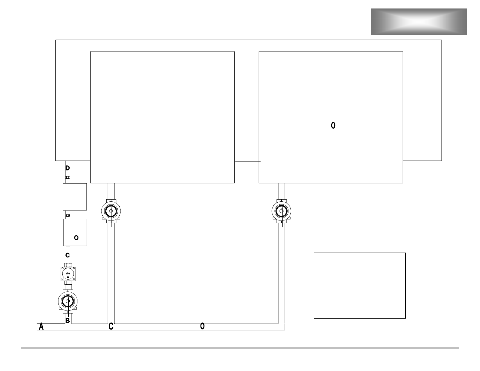
AGC START-UPS
Griddle / Charbroiler
AGC AGC
ACV
ACV
Regulator
Manual Shut-off
Legend:
ACV = Automatic Cut-off Valve
A = 1” Pipe
B = Reduction to ¾” Pipe
C = Reduction to ½” Pipe
D = Increase to ¾” Pipe
O = Optional Second AGC Parts
7
Page 9
GENERAL
GENERAL
The suggested time and temperature chart (below) is provided as a guide for the products
listed only.
CAUTION: ALWAYS KEEP THE AREA NEAR THE APPLIANCE FREE
FROM COMBUSTIBLE MATERIALS.
CAUTION: KEEP FLOOR IN FRONT OF EQUIPMENT CLEAN AND
DRY. IF SPILLS OCCUR, CLEAN IMMEDIATELY, TO
AVOID THE DANGER OF SLIPS OR FALLS.
SUGGESTED TIMES AND TEMPERATURES WITHOUT AGC
HOOD
PRODUCTS
HAMBURGER
2 patties per LB 350 6 to 8
4 patties per LB 350 4 to 6
6 patties per LB 350 3 to 4
STEAKS
1/2 to 3/4 inch thick, cooked medium 375 5 to 7
3/4 to 1 inch thick, cooked medium 375 8 to 10
Lamb Chops 350 6 to 8
Pork Chops 350 6 to 8
Salmon 350 6 to 8
Halibut 325 6 to 8
Snapper 325 6 to 8
Hashbrown Potatoes 375 3 to 4
Bacon 350 3 to 4
Sausage Links or Patties 350 3 to 4
Ham (Pre-cooked) 375 2
Eggs 275 2 to 4
Note: The times and temperatures in this chart are intended as a general guide and starting point. Your
actual times and temperatures may vary from this chart.
If different temperature settings are to be used, select one side of the griddle and
operate at the lowest temperature. Adjoining sections should be set at
progressively higher temperatures. Do not try to operate the end sections hot and
the center sections cool.
TEMPERATURE
(F)
350
TIME (MIN)
8
Page 10

GENERAL CONT’D
OPERATIONS
An understanding of how the griddle sections are controlled will be a valuable aid in
loading your griddle.
Each 12-inch section of your griddle is independently controlled by a temperature
controller. The temperature control sensor is mounted in the center of each cooking
section under the griddle plate.
If the product is loaded directly over the temperature sensor, that section will turn on and
the burner will heat the entire cooking section. If the product is loaded to the side, front
or back of the temperature sensor, the thermostat will react to the temperature change
much slower.
During slow periods with minimal loads, do not load directly over the thermostat sensors
as this will unnecessarily turn the burners on and overheat the remainder of the section
not being utilized.
Turn the product and continue cooking until it has reached its desired degree of doneness.
Remove the product from the griddle.
When reloading the griddle, first use the griddle surface on which a previous load was not
placed. This will insure you the proper griddle temperature.
9
Page 11

G-TI
Power Switch to “ON” position.
120 VAC supplied to primary of 120/24 Transformer.
Transformer energizes.
24 VAC to Pilot valve.
Pilot valve opens.
120 VAC to Spark Module.
Pilots ignite.
Flame switch closes.
24 VAC to Power Switch.
Power switch to “ON” position.
24 VAC to Thermostat.
24 VAC to Main Burner Valve.
Main Burner ignites.
G-TDSI
Power Switch to “ON” position.
120 VAC to 120/24 Transformer.
Transformer energizes.
24 VAC to Thermostat.
24 VAC to Solenoid Valve.
24 VAC between 2 and ground at Spark Module.
Main Burner ignites.
SEQUENCE OF OPERATION
G-EI
Power Switch to “ON” position.
120 VAC to 120/24 Transformer.
Transformer energizes.
24 VAC to Pilot Valve.
Pilot valve opens.
120 VAC to Spark Module.
Pilots ignite.
Flame switch closes.
24 VAC at pins # 9 and # 7 of Temperature control board. (The Red L.E.D indicator light on the
circuit board is a indication that there is 24 VAC to the board.)
Temperature set on 12-position switch.
24 VAC at Main burner valve from pin 6 on board. (The Yellow L.E.D indicator light on the circuit
board is a indication that the sensor is calling for heat and to close the triac on the board.)
Main burner ignites.
10
Page 12

SEQUENCE OF OPERATION CONT’D
G-EDSI
Power Switch to “ON” position.
120 VAC to 120/24 Transformer.
Transformer energizes.
24 VAC at pins # 9 and # 7 of Temperature control board. (The Red L.E.D indicator light on the
circuit board is a indication that there is 24 VAC to the board.)
24 VAC at pin 2 on Spark Module from pin 8 on board. (The Yellow L.E.D indicator light on the
circuit board is a indication that the sensor is calling for heat and to close the triac on the board).
24 VAC to Solenoid Valve.
Main Burner ignites.
AGC HOOD
Power to motor.
Air switch closes.
120 VAC to transformer.
Transformer energizes.
24 VAC to Tilt switch.
Hood is lowered.
24 VAC between “TH” and ground on spark module.
24 VAC at solenoid valve.
Hood ignites.
11
Page 13

TROUBLESHOOTING
NO POWER
PROBABLE CAUSE CORRECTIVE ACTION
Power switch is not turned on ¾ Turn power switch on.
Defective power switch ¾ Check power switch for normal operation. Replace as necessary.
Tripped breaker
Defective power cord
¾ Reset breaker.
¾ Replace power cord.
If 120 VAC is measured at primary side of transformer.
¾ Check for 24 volts on the secondary side.
¾ If voltage not present replace transformer.
No Power at Valve
PROBABLE CAUSE CORRECTIVE ACTION
Faulty flame switch ¾ Check switch for normal operation. Replace as necessary.
Defective Thermostat (T
models)
Faulty Temperature board
(EDSI and EI models)
Defective probe (EDSI and EI
models)
Faulty Ignition module (EDSI
and TDSI models)
¾ Check Thermostat for normal operation. Replace as necessary.
¾ Check input and output voltage. 24 volt ac.
¾ Verify probe resistance. Replace if open.
¾ Check input and output voltages. 24 volts ac.
Faulty electrode assembly
(EDSI and TDSI models)
¾ Replace as necessary.
12
Page 14

NO PILOT
PROBABLE CAUSE CORRECTIVE ACTION
TROUBLESHOOTING G-EI
Gas valve off
Blocked or pinched gas line
Defective valve
No voltage at pilot solenoid
valve
Plugged vent on the regulator
No Burner
PROBABLE CAUSE CORRECTIVE ACTION
Gas valve off
Blocked or pinched gas line
Defective valve / Sticking
No voltage at pilot solenoid
valve
Plugged vent on the regulator
Plugged pilot light
Faulty flame switch
¾ Turn it on.
¾ Clear pipe or replace gas line.
¾ Verify Ohms on the coil of the valve at 36Ω.
¾ Check transformer for normal operation.
¾ Clear hole in regulator vent.
¾ Turn it on.
¾ Clear pipe or replace gas line.
¾ Verify Ohms on the coil of the valve at 36Ω.
¾ Check transformer for normal operation.
¾ Clear hole in regulator vent.
¾ Clean or replace.
¾ Replace.
13
Page 15

TROUBLESHOOTING GEI CONT’D
Heat Erratic
PROBABLE CAUSE CORRECTIVE ACTION
Flame to low. Plugged orifice
or vent on regulator
Flame lifting off of burner ports ¾ Adjust air shutters. Adjust gas pressure.
Flame not present on one side
of burner ports
Loose or greasy connections in
the control wiring or at control
boards.
Faulty probe or incorrect probe
placement
¾ Clean of replace orifice. Adjust gas pressure. Clean vent on regulator.
¾ Drill 2 – 3 # 53 holes at the corners of the burners to help flame
around U of burner or replace burner.
¾ Fix loose connections and spray connections with contact cleaner.
¾ Verify probe resistance. Check probe placement.
NOTE: Follow Lang griddle calibration procedure to verify the
temperature.
14
Page 16

TROUBLESHOOTING AGC
Hood will not light
PROBABLE CAUSE CORRECTIVE ACTION
Defective Module ¾ Confirm that igniter is sparking.
¾ Check for 24 VAC between “TH” and ground.
If 24 VAC is present:
¾ Replace module.
If 24 VAC is not present:
¾ Check Tilt switch for normal operation.
Defective Solenoid Valve ¾ Check for 24 VAC at Coil.
If 24 VAC is present:
¾ Check Coil for 36 Ω.
¾ Replace as necessary.
If 24 VAC is not present:
¾ Check Module for normal operation.
Defective Transformer ¾ Confirm incoming voltage.
¾ Confirm outgoing voltage.
Defective Air Switch ¾ Check switch for continuity.
¾ Confirm motor is running.
Defective Motor ¾ Confirm that motor is getting voltage.
Improper Air Mixture ¾ Adjust Air mixture.
Gas Pressure to low ¾ Adjust Gas pressure. (NG=3.5”W/C, LP=8”W/C)
Plugged Pilot enrichment
Orifice
Spark ignition to far or to close
to Burner tiles
¾ Clear or Replace orifice.
¾ Adjust to 1/4” away from tile.
15
Page 17

TECHNICAL DATA
TRANSFORMER RESISTANCE
TRANSFORMER Part # Input Primary Secondary Output
¾ 120/24 Volt 31400-07 120 Volt
18.9 Ω 1 Ω
24 Volt
SOLENOID VALVE RESISTANCE
VALVE Part # Coil
¾ 24 Volt 80502-03
36 Ω
TEMPERATURE SELECTOR SWITCH RESISTANCE (30304-22)
NOTES: Make checks from the back of the switch with wires still connected on pins 1 and 3. (Pin
one being on the left hand side)
Switch Position Resistance
1 Open
2 154
3 286
4 400
5 500
6 578
7 632
8 668
9 674
10 656
11 611
12 539
16
Page 18

TECHNICAL DATA CONT’D
"
Lang Griddle Calibration Check Procedures
To verify calibration:
1. Set the Griddle temperature to 350°F on all sections. (It should take approximately 22 minutes to
reach temperature.)
2. Let the griddle reach 350°F and cycle at least three times.
3. Measure 6” from the left, and 11 1/2” from the front of the plate for the first check point. (This will
check the center of the probe for the first cooking section.)
4. Each checkpoint is located every 12” to the right from the last point, and always 11 1/2” from the
front. (See Illustration 1.)
11
1/ 2"
12"6" 12"
11
1/ 2"
48
Illustration 1
12"
2"
6"
5"
30"
5. Record the on temperature and the off temperature as each sections cycles.
6. Repeat the recording three times. (Use Table 1 to record your temperatures.)
Temperature Section 1 Section 2 Section 3 Section 4
On
Off
On
Off
On
Off
Average
17
Page 19

TECHNICAL DATA CONT’D
PROBE RESISTANCE
TEMP RESISTANCE VOLT DROP TEMP RESISTANCE VOLT DROP
70° 556 Ω
80° 569 Ω
90° 583 Ω
100° 596 Ω
110° 610 Ω
120° 623 Ω
130° 637 Ω
140° 651 Ω
150° 665 Ω
160° 678 Ω
170° 694 Ω
180° 709 Ω
190° 724 Ω
200° 739 Ω
210° 754 Ω
220° 769 Ω
1.11
1.14
1.17
1.19
1.22
1.25
1.27
1.3
1.33
1.36
1.39
1.42
1.45
1.48
1.51
1.54
290° 881 Ω
300° 897 Ω
310° 914 Ω
320° 931 Ω
330° 948 Ω
340° 965 Ω
350° 983 Ω
360° 1000 Ω
370° 1018 Ω
380° 1036 Ω
390° 1054 Ω
400° 1072 Ω
410° 1090 Ω
420° 1109 Ω
430° 1127 Ω
440° 1146 Ω
1.76
1.79
1.83
1.86
1.90
1.93
1.97
2.00
2.04
2.07
2.11
2.14
2.18
2.22
2.25
2.29
230° 785 Ω
240° 800 Ω
250° 816 Ω
260° 832 Ω
270° 848 Ω
280° 864 Ω
Probe is factory checked at 350 °F. Must be completely disconnected from circuit board when measuring
1.57
1.60
1.63
1.66
1.70
1.73
NOTE
probe resistance.
18
450° 1165 Ω
460° 1184 Ω
470° 1204 Ω
480° 1223 Ω
490° 1243 Ω
500° 1263 Ω
2.33
2.37
2.41
2.45
2.49
2.53
Page 20

Primary
120 Volt
18.9 Ω
Transformer
31400-07
TECHNICAL DATA CONT’D
Secondary
24 Volt
1.0 Ω
-
-
-
Check Resistance
on pins 1 & 3 wile
still plugged in.
Pos. Res.
1 Open
2
154Ω
3
286Ω
4
400Ω
5
500Ω
6
578Ω
7
632Ω
8
668Ω
9
674Ω
10
656Ω
11
611Ω
12
539Ω
Burner Valve
80502-03
24 Volt
36Ω
-
19
Page 21

WIRING DIAGRAM G-TI
20
Page 22

WIRING DIAGRAM G-TDSI
21
Page 23

WIRING DIAGRAM G-EI
22
Page 24

WIRING DIAGRAM G-EDSI
23
Page 25

AGC HOOD
24
Page 26

G-24TI, G-36TI, G-48TI, G-60TI, G-72TI
GAS ACCU-TEMP GRIDDLE
DESCRIPTION
Switch, Toggle On-Off 30303-06
Thermostat 450°F Griddle
Terminal Strip 4 Pole 30501-03
Power Cord with Molded Plug 31107-02
Transformer 120/24 VAC 31400-07
Pilot Light 208/240V 6” Lead Black Body 31601-01
Grooved Griddle Cleaning Tool 50100-05
Grooved Griddle Cleaning Tool – Replacement Fingers 50100-051
Grooved Griddle Cleaning Tool – Replacement Blades 50100-052
Knob Temperature Control 70701-16
Legs 4” Stainless Steel 72500-02
Burner “J” Tube Steel 80002-09-1
Burner “J” Tube Steel Left Hand Section 80002-07-1
Pilot Burner Assembly Sections 2, 3, 4, 5 & 6 80201-24
Pilot Burner Assembly Section 1 (and 4 on 6ft Units Only) 80201-25
Module Spark Ignitor 80300-03
Orifice Main Burner #42 DRL NG 80400-11
Orifice Main Burner #53 DRL LP 80400-12
Orifice Pilot Burner .018 DRL NG 80401-01
Orifice Pilot Burner .010 DRL LP 80401-02
Regulator Gas Set 5” NG Griddle 80501-04
Regulator Gas Set 10” LP Griddle 80501-05
Regulator Gas Spring Conversion Kit NG to LP 80501-07
Valve Solenoid Gas 24 VAC 80502-03
Flame Switch 24” Long Capillary 80506-01
PART NO.
30402-27
25
Page 27

G-24TDSI, G-36TDSI, G-48TDSI, G-60TDSI, G-72TDSI
GAS ACCU-TEMP GRIDDLE
DESCRIPTION
Switch, Toggle On-Off 30303-06
Thermostat 450°F Griddle
Terminal Strip 3 Pole 30501-02
Power Cord with Molded Plug 31107-02
Transformer 120/24 VAC 31400-07
Transformer 240/24 VAC 31400-10
Pilot Light 208/240V 6” Lead Black Body 31601-01
Grooved Griddle Cleaning Tool 50100-05
Grooved Griddle Cleaning Tool – Replacement Fingers 50100-051
Grooved Griddle Cleaning Tool – Replacement Blades 50100-052
Knob Temperature Control 70701-16
Silicone Nipple 7mm 70801-10
Legs 4” Stainless Steel 72500-02
Burner “J” Tube Steel 80002-09-1
Burner “J” Tube Steel Left Hand Section 80002-07-1
Module Spark Ignitor 60101-910
DSI Electrode Assembly 80302-05
Orifice Main Burner #42 DRL NG 80400-11
Orifice Main Burner #53 DRL LP 80400-12
Orifice 90° Fitting NG
Orifice 90° Fitting LP
Regulator Gas Set 5” NG Griddle 80501-04
Regulator Gas Set 10” LP Griddle 80501-05
Regulator Gas Spring Conversion Kit NG to LP 80501-07
Valve Solenoid Gas 24 VAC 80502-03
Wire Harness #1 (Sense/Spark) EZG-701
PART NO.
30402-27
80401-01
80401-02
26
Page 28

G-2EI, G-3EI, G-4EI, G-5EI, G-6EI
GAS SELECTRONIC GRIDDLE
DESCRIPTION
Switch Toggle On-Off for Each 1ft Section (After F-89817) 30303-04
Switch Toggle On-Off 30303-06
Switch Temperature Control 12 Position 42” Harness (Before D-45887) 30304-11
Switch Temperature Control 12 Position 175-450°F (After E-51388)
Terminal Strip 3 Pole (After E-51388) 30501-02
Terminal Strip 4 Pole (After E-51388) 30501-03
Power Cord with Molded Plug 31107-02
Transformer 120/24 VAC 31400-07
Pilot Light 208/240V 6” Lead Black Body (After E-51388) 31601-01
Circuit Board Temperature Control (Before D-45887) 40101-07
Circuit Board Temperature Control (After E-51388) 40101-19
Probe Temperature Sensor (Before D-45887) 41100-06
Probe Temperature Sensor (From E-51388 to E-89816) 41100-13
Probe Temperature Sensor (After F-89817) 41100-21
Grooved Griddle Cleaning Tool 50100-05
Grooved Griddle Cleaning Tool – Replacement Fingers 50100-051
Grooved Griddle Cleaning Tool – Replacement Blades 50100-052
Panel Label 60301-29
Catch Spring with Striker Plate (Before D-45887) 70602-02
Catch Magnetic Door (After E-51388) 70602-06
Knob Temperature Control 70701-28
Spacer Support 1/2” Nylon 70801-07
Burner “J” Tube Steel 80002-09-1
Burner “J” Tube Steel Left Hand Section 80002-07-1
Pilot Burner Assembly Sections 2, 3, 4, 5, & 6 (Before D-45887) 80201-10
Pilot Burner Assembly Section 1 (and 4 on 6ft Units Only) (Before D-45887) 80201-19
Pilot Burner Assembly Sections 2, 3, 4, 5, & 6 (After E-51388) 80201-24
Pilot Burner Assembly Section 1 (and 4 on 6ft Units Only) (After E-51388) 80201-25
Spark Module Ignitor 80300-03
Orifice Main Burner #42 DRL NG 80400-11
Orifice Main Burner #53 DRL LP 80400-12
Orifice Pilot Burner .018 DRL NG 80401-01
Orifice Pilot Burner .010 DRL LP 80401-02
Regulator Gas Set 5” NG Griddle 80501-04
Regulator Gas Set 10” LP Griddle 80501-05
Regulator Gas Spring Conversion Kit NG to LP 80501-07
Valve Solenoid Gas 120 VAC (Before D-45887) 80502-01
Valve Solenoid Gas 24 VAC (From E-51388 to E-89816) 80502-03
Valve Combination Gas (Before D-45887) 80505-04
Flame Switch 24” Long Capillary 80506-01
PART NO.
30304-22
27
Page 29

G-2EDSI, G-3EDSI, G-4EDSI, G-5EDSI, G-6EDSI
GAS SELECTRONIC GRIDDLE
DESCRIPTION
Switch Toggle On-Off 30303-06
Switch Toggle On-Off SPST 30303-18
Switch Temperature Control 12 Position 175-450°F
Terminal Strip 3 Pole 30501-02
Power Cord with Molded Plug 31107-02
Transformer 120/24 VAC 31400-07
Pilot Light 208/240V 6” Lead Black Body 31601-01
Circuit Board Temperature Control 40101-19
Probe Temperature Sensor 41100-21
Grooved Griddle Cleaning Tool 50100-05
Grooved Griddle Cleaning Tool – Replacement Fingers 50100-051
Grooved Griddle Cleaning Tool – Replacement Blades 50100-052
Panel Label 60301-29
Catch Magnetic Door 70602-06
Knob Temperature Control 70701-28
Spacer Support 1/2” Nylon 70801-07
Silicon Nipple 7mm 70801-10
Burner “J” Tube Steel 80002-09-1
Burner “J” Tube Steel Left Hand Section 80002-07-1
Spark Module Ignitor 60101-910
DSI Electrode Assembly 80302-05
Orifice Main Burner #42 DRL NG 80400-11
Orifice Main Burner #53 DRL LP 80400-12
Regulator Gas Set 5” NG Griddle 80501-04
Regulator Gas Set 10” LP Griddle 80501-05
Regulator Gas Spring Conversion Kit NG to LP 80501-07
Valve Solenoid Gas 24 VAC 80502-03
Wire Harness #1 (Sense/Spark) EZG-701
Wire Harness #2 EZG-705
PART NO.
30304-22
28
Page 30

AGC
GAS CLAMSHELL
DESCRIPTION
Tube #1 103-14
Hood Skirt Left Side 103-193
Hood Skirt Right Side 103-194
Hood Skirt Front Side w/ Hinge 103-197
Spark Cover 103-3
Tube #2
Tube #3 103-64
Tube #4 103-70
Screw 3/8” x 16 x 12” 20104-37
Motor 120V 30200-44
Switch Mercury Tilt 30307-01
Clip Mount Mercury Tilt Switch 30307-02
Switch Air w/ 1/4” Hosebarb 30308-01
Terminal Strip 3 Pole 30501-02
Relay 24 VAC 30600-04
Power Cord with Molded Plug 31107-06
Transformer 120/24 VAC 31400-07
Cap. Blower Start 40704-04
Wire Guard 50201-08
Spring Compression Inner 51002-05
Hood Spring AGC 51002-11
Burner Tile Assembly 51100-59
Hood Wrap 60101-851
Flapper 60102-191
Union Elbow 90 Degrees 70101-28
Brass Tube Tee 70101-50
Fitting 1/4” HP to 1/2” NPT 70101-61
Hose Flex Gas 27” 1/2” NPT 70101-62
Bronze Bearing 5/8” ID x 3/4” OD x 5/8” Lg 70201-06
Bronze Bearing 5/8” ID x 3/4” OD x 1” Lg 70201-07
Conduit Connector 3/8” Flex 70505-06
Conduit Connector 3/8” 90° Flex
Handle 70603-24
Hose 1/4” Neoprene Low Pressure 74001-01
Spark Module 80300-10
Igniter & Sensor Assembly 80302-06
Pilot Orifice Enrichment Tube 80401-05
90 Degree Fitting w/ #29 DRL NG 80403-04
90 Degree Fitting w/ #44 DRL LP 80403-05
Regulator Gas Set 3 1/2” NG 80501-10
Valve Solenoid Gas 24V 80502-03
Seal Fiber GCH-232-1
Washer AGC GCH-232-2
Spark Wire GCH-515-1
Sensor Wire GCH-516-1
PART NO.
103-61
70505-07
29
 Loading...