

Page 1
Owner’s Manual
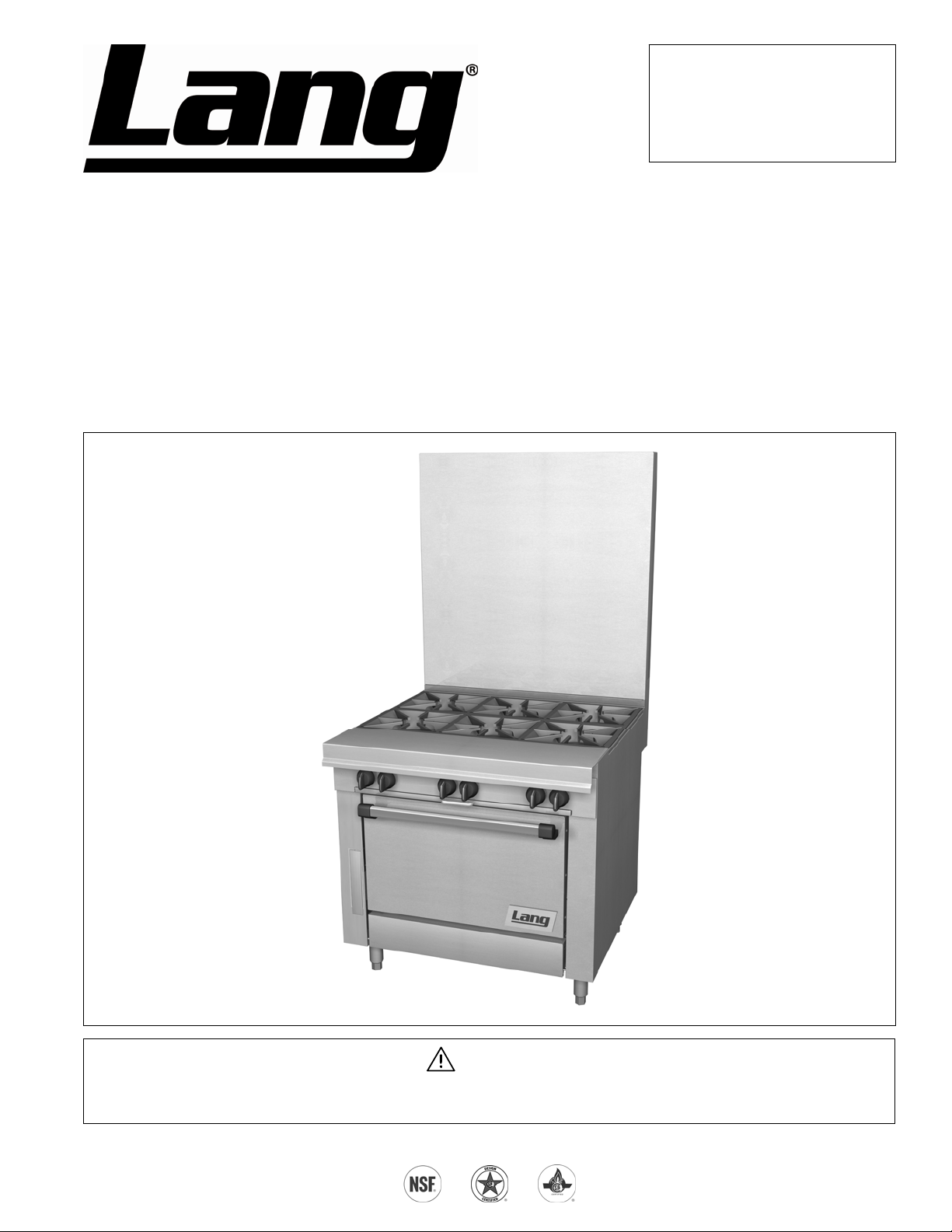
Chef Series Sectional Range
IMPORTANT FOR FUTURE REFERENCE
Please complete this information and retain
this manual for the life of the equipment:
Model #: __________________________
Serial #: __________________________
Date Purchased: ___________________
Charbroiler Models
Flush Open Burner Models
Graduated Hot-Top Models
Uniform Hot-Top Models
Standard Griddle Models
Step-Up Open-Burner Models
Thermostatic Griddle Models
Combination Open-Burner Hot-Top Models
Combination Open-Burner Griddle Models
WARNING
Improper installation, adjustment, alteration, service, or maintenance can cause property damage, injury, or death.
Read installation, operation, and maintenance instructions thoroughly before installing or servicing this equipment.
10 Sunnen Drive, St. Louis, MO 63143 USA • www.langworld.com
M
ANUAL 1192040 REV 1 (01/10)
$30.00
CHEF SERIES SECTIONAL RANGE
MANUAL SECTION SR
Page 2
SAFETY PRECAUTIONS CHEF SERIES SECTIONAL RANGE
SAFETY PRECAUTIONS
Before installing and operating this equipment, be sure everyone involved in its operation is fully trained and aware of
precautions. Accidents and problems can be caused by failure to follow fundamental rules and precautions.
The following symbols, found throughout this manual, alert you to potentially dangerous conditions to the operator,
service personnel, or to the equipment.
DANGER
WARNING
CAUTION
NOTICE
This symbol warns of immediate hazards that will result in severe injury or death.
This symbol refers to a potential hazard or unsafe practice that could result in injury or
death.
This symbol refers to a potential hazard or unsafe practice that could result in injury,
product damage, or property damage.
This symbol refers to information that needs special attention or must be fully understood,
even though not dangerous.
WARNING
FIRE HAZARD
FOR YOUR SAFETY
Do not store or use gasoline or other flammable vapors and liquids in the vicinity of cookin g appliances.
Keep area around cooking appliances free and clear of combustibles.
Purchaser of equipment must post in a prominent location detailed instructions to be followed in the event the
operator smells gas. Obtain the instructions from the local gas supplier.
WARNING
BURN HAZARD
Contact with hot surfaces will cause severe burns. Always use caution when operating cooking appliances.
WARNING
EXPLOSION AND ASPHYXIATION HAZARD
In the event a gas odor is detected, shut down equipment at the main gas shut-off valve and immediately call
the emergency phone number of your gas supplier.
Improper ventilation can result in headaches, drowsiness, nausea, and could result in death. Do not obstruct the
flow of combustion and ventilation air to and from cooking appliances.
WARNING
ELECTRIC SHOCK HAZARD
For appliances that use electric power, disconnect the power to the appliance before cleaning. Do not remove
panels that require tools to remove.
NOTICE
Lang appliances are intended for commercial use only. Not for household u se.
Warranty will be void if service work is performed by other than a qualified technician, or if other than genuine
Lang replacement parts are installed.
Give this Owner’s Manual and important papers to the proper authority to retain for future reference.
Published in the United States of America.
PAGE 2 OF 76 OWNER’S MANUAL 1192040 REV 1 (01/10)
Page 3
CHEF SERIES SECTIONAL RANGE INTRODUCTION
INTRODUCTION
Congratulations! You have purchased one of the finest pieces of heavy-duty commercial cooking equipment on the
market.
You will find that your new equipment, like all Lang equipment, has been designed and manufactured to meet the
toughest standards in the industry. Each piece of Lang equipment is carefully engineered and designs are verified
through laboratory tests and field installations. With proper care and field maintenance, you will experien ce years of
reliable, trouble-free operation. For best results, read this manual carefully.
RETAIN THIS MANUAL FOR FUTURE REFERENCE.
This manual is for Lang Chef Series Sectional Ranges.
This manual does NOT cover sectional fryers, fryer filter systems, salamander broilers, upright broilers, cheese
melters, or refrigerated bases. Those appliances have their own manuals.
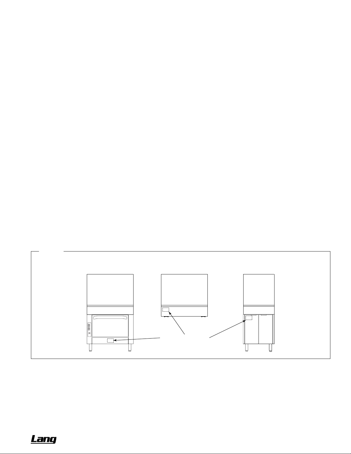
The location of the serial plate depends on the type of base (see
serial plate is located on the backside of the kick-plate below the oven door (lift the kick-plate straight up and tilt the
top edge out and down.) On models with a cabinet base, the serial plate is located inside the left cabinet door. On
modular (countertop) models, the serial plate is located inside the front valve panel.
Read these instructions carefully before attempting installation. Installation and initial startup should be performed by
a qualified installer. Unless the installation instructions for this product are followed by a qualified service technician (a
person experienced in and knowledgeable with the installation of commercial gas and/or electric cooking equipment)
then the terms and conditions on the Manufacturer’s Limited Warranty will be rendered void and no warranty of any
kind shall apply.
In the event you have questions concerning the installation, use, care, or service of the product, contact:
Lang Technical Service
10 Sunnen Drive
St. Louis, MO 63143 USA
Phone: (800) 807-9054 Fax: (314) 781-2714
www.langworld.com
Figure 1
Location of Serial Plate
Figure 1 below). On models with oven bases, the
Location of Serial Plate
OWNER’S MANUAL 1192040 REV 1 (01/10) PAGE 3 OF 76
Page 4

SPECIFICATIONS CHEF SERIES SECTIONAL RANGE
SPECIFICATIONS
NOTICE
Local codes regarding installation vary greatly from one area to another. The National Fire Protection Association,
Inc., states in its NFPA 96 latest edition that local codes are the “authority having jurisdiction” when it comes to
installation requirements for equipment. Therefore, installations should comply with all local codes.
Lang reserves the right to change specifications and product design without notice. Such revisions do not entitle
the buyer to corresponding changes, additions, or replacements for previously purchased equipment.
Lang appliances are intended for commercial use only, not for household use.
The installation must conform with local codes, or in the absence of local codes, with the National Fuel Gas Code,
ANSI Z223.1, Natural Gas Installation Code, CAN/CGA-B149.1, or the Propane Installation Code CAN/CGA-
B149.2, as applicable, including:
1. The appliance and its individual shutoff valve must be disconnected from the gas supply piping system during
any pressure testing of that system at test pressures in excess of 1/2 psi (3.45 kPa).
2. The appliance must be isolated from the gas supply piping system by closing its individual manual shutoff valve
during any pressure testing of the gas supply piping system at test pressures equal to or less than 1/2 psi (3.45
kPa).
CLEARANCES
WARNING
MINIMUM CLEARANCES FROM COMBUSTIBLE CONSTRUCTION
There must be adequate clearance between the sectional range and combustible construction. Clearance must
also be provided for servicing and for operation.
Open-Top
Standard-Burner
Models
Sides 10" 13" 10" 10" 6"
Back 6" 6" 12" 12" 6"
Floor* 0" 0" 0" 0" 0"
Do NOT install sectional charbroilers next to combustible materials.
* Models with 6" legs or casters are suitable for installation on combustible floors.
Adequate clearance must be provided in the aisle in front of the unit to permit operation (including opening of
doors and/or removal of grease drawers, drippings trays, and/or oven racks), as well as for servicing. No ad ditional
clearance is required for servicing as the sectional range is serviceable from the front.
Models with a convection-type oven require a minimum clearance of 2" between the motor on the back and noncombustible construction. Care must be taken to provide adequate air circulation to prevent the motor from
overheating.
Open-Top
45K-Burner
Models
Griddle
Models
Uniform Hot-Top
Models
Graduated
Hot-Top
Models
Minimum clearance from noncombustible construction is zero on the sides and back for all models (except for
models with a convection-type oven).
The high-temperature flue products flow out through the top of the flue riser of all models, and from the top of
open-top and charbroiler models. Installation under a vented hood is recommended.
Salamander broilers and cheese melters mounted on the flue riser of a sectional range may require additional
minimum clearances (see the documentation for those appliances).
PAGE 4 OF 76 OWNER’S MANUAL 1192040 REV 1 (01/10)
Page 5
CHEF SERIES SECTIONAL RANGE SPECIFICATIONS
VENTILATION
WARNING
Improper ventilation can result in personal injury or death. Ventilation which fails to properly remove flue products
can cause headaches, drowsiness, nausea, or could result in death.
All gas appliances must be installed in such a manner that the flow of combustion and ventilation air is not
obstructed. Provisions for adequate air supply must be provided. Do not obstruct the area under the control panel
or below the oven door (on the front), or the area below the flue riser (on the back) as combustion air enters
through these areas.
NOTICE
Proper ventilation is the owner’s responsibility. Any problem due to improper ventilation will not be covered by the
warranty.
Be sure to inspect and clean the ventilation system according to the ventilation equipment manufacturer’s
instructions.
Air for combustion enters from the front below the valve panel, as well as from the rear into the burner box. Ranges
with solid tops (griddles and hot-tops) vent their flue products up the flue riser. On units with a base oven, combustion
air enters from the front below the oven door. Oven flue products are vented up the flue riser.
Lack of sufficient ventilation will cause poor burner and pilot operating characteristics, resulting in inefficient
performance. Such conditions also cause high ambient temperatures at the manifold area and create valve and
thermostat problems.
If a ventilation canopy is used, it is recommended that the canopy extend 6" past the sectional range and that the
bottom edge be located 6'6" from the floor. Filters should be installed at an angle of 45° or more from the horizontal.
This position prevents dripping grease, and facilitates collecting the run-off grease in a drip pan under the filter.
A strong exhaust fan tends to create a vacuum in the room and may interfere with burner performance or may
extinguish pilot flames. Fresh air openings approximately equal to the fan area will relieve such a vacuum. The
exhaust fan should be installed at least 2" above the top of the flue riser.
If the sectional range is connected directly to an outside flue, a CSA design certified down draft diverter must be
installed.
In case of unsatisfactory performance by any gas appliance, check the appliance with the exhaust fan turned OFF. Do
this only long enough to check whether doing so corrects any problems with equipment performance. Then turn the
exhaust fan back on and let it run to remove any exhaust that may have accumulated during the test.
GAS SUPPLY
The sectional range is design-certified for operation on natural or propa ne gases. The sectional range is shipped
configured and adjusted for the type of gas specified by the purchaser, which is indicated on the serial plate (see
Figure 1 on page 3). Connect the sectional range ONLY to the type of gas for which it is configured and adjusted.
Each section has a 1-1/4" front gas manifold that can be coupled to adjacent section(s). Sections can be ordered with
an optional 1" rear gas connection with a male NPT connector. Minimum supply pressure is 7" W.C. for natural gas,
11" W.C. for propane. An external pressure regulator and shut off valve must be provided. If using a flexible-hose gas
connection, the I.D. of the hose must not be smaller than the connector on the unit and must comply with ANSI
Z21.69. Provide an adequate means of restraint to prevent undue strain on the gas connection.
If applicable, the vent line from the gas appliance pressure regulator shall be installed to the outdoors in accordance
with local codes, or in the absence of local codes, with the National Fuel Gas Code, ANSI Z223.1, Natural Gas
Installation Code, CAN/CGA-B149.1, or the Propane Installation Code CAN/CGA-B149.2, as applicable.
An adequate gas supply is imperative. Undersized or low pressure lines will restrict the volume of gas required for
satisfactory performance. A 1/8" pressure tap is located on the manifold to measure the manifold pressure. The
supply line to the sectional range should be no smaller than the inside diameter of the pipe on the se ctional range to
which it is connected.
OWNER’S MANUAL 1192040 REV 1 (01/10) PAGE 5 OF 76
Page 6
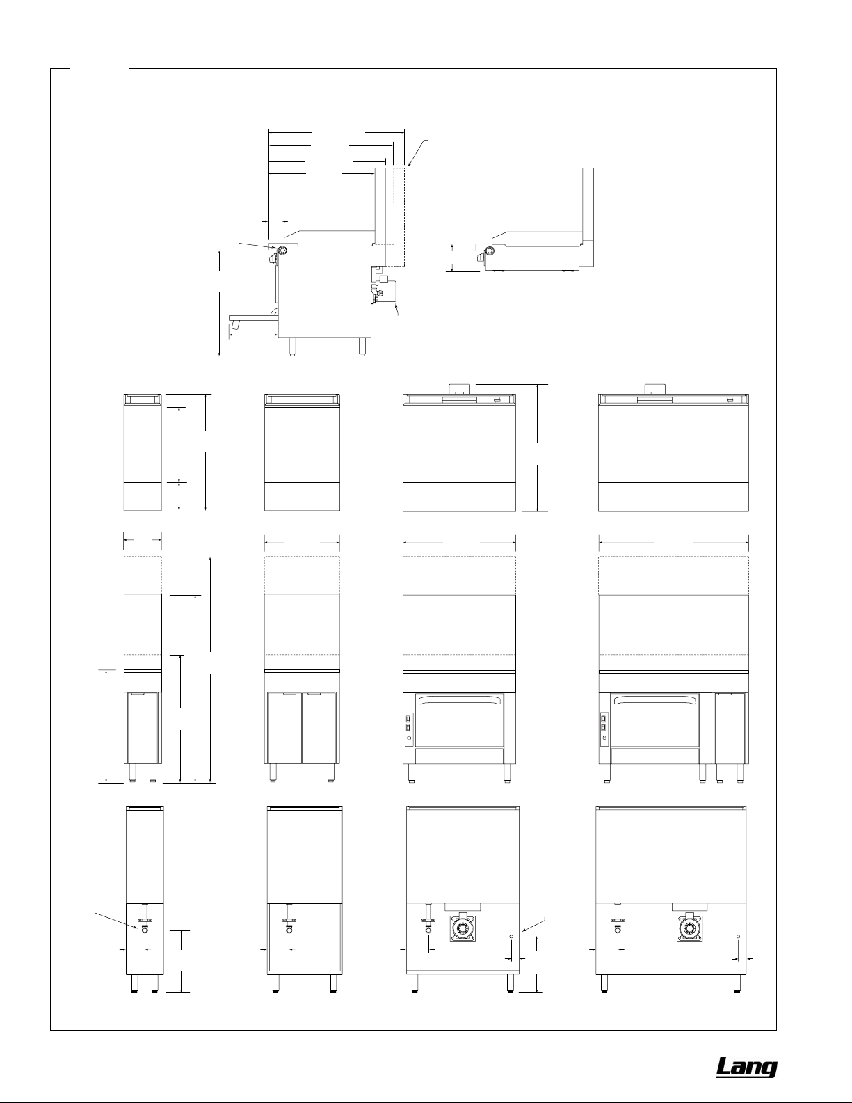
SPECIFICATIONS CHEF SERIES SECTIONAL RANGE
Figure 2
Dimensions
36" Flue Riser
12"
(305)
24"
(610)
9" (229)
33-3/4"
37-3/4"
(959)
(859)
Front Gas
Manifold
15-3/4"
(400)
37-3/4" (959)
34" (864)
4-1/2" (114)
SIDE VIEW
24" (610)
43-3/4" (1111)
40" (1016)
Motor for
Convection
Oven Model
Flue riser for “deep” depth-option extends rearward 6"
(cooking suface area is same as for “standard” depth).
8-1/2" (216)
SIDE VIEW of Modular Model
39-3/4"
(1010)
36" (914)
48" (1219)
24" Flue Riser
5" Flue Riser
36"
(914)
Optional
Rear Gas
Connection
6" (152)
41"
(1041)
20"
(508)
60"
(1524)
72"
(1829)
7" (178)
7" (178)
2-1/2" (64)
Electrical
Connection
for Oven
Models
18"
(457)
7" (178)
2-1/2" (64)
PAGE 6 OF 76 OWNER’S MANUAL 1192040 REV 1 (01/10)
Page 7
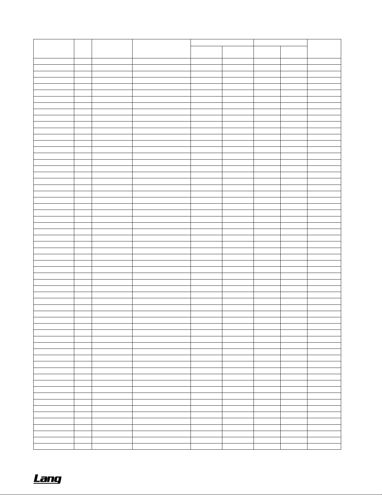
CHEF SERIES SECTIONAL RANGE SPECIFICATIONS
UTILITY REQUIREMENTS AND CRATED WEIGHT
Model Width Base Type Top Type
LGR12C-B 12" cabinet flush 35K open-burner 70,000 60,000 - - 225 (102)
LGR12C-G 12" cabinet standard griddle 32,000 28,000 - - 225 (102)
LGR12C-H 12" cabinet uniform hot top 32,000 28,000 - - 180 (82)
LGR12N-B 12" modular flush 35K open-burner 70,000 60,000 - - 175 (79)
LGR12N-G 12" modular standard griddle 32,000 28,000 - - 175 (79)
LGR12N-H 12" modular uniform hot top 32,000 28,000 - - 130 (59)
LGR24C-BB 24" cabinet flush 35K open-burner 140,000 120,000 - - 480 (218)
LGR24C-BB-SU 24" cabinet step-up 35K open-burner 140,000 120,000 - - 480 (218)
LGR24C-CC 24" cabinet charbroiler 64,000 56,000 - - 360 (163)
LGR24C-GG 24" cabinet standard griddle 64,000 56,000 - - 300 (136)
LGR24C-HH 24" cabinet uniform hot top 64,000 56,000 - - 280 (127)
LGR24C-TT 24" cabinet thermostatic griddle 64,000 56,000 - - 300 (136)
LGR24N-BB 24" modular flush 35K open-burner 140,000 120,000 - - 395 (179)
LGR24N-BB-SU 24" modular step-up 35K open-burner 140,000 120,000 - - 395 (179)
LGR24N-CC 24" modular charbroiler 64,000 56,000 - - 360 (163)
LGR24N-GG 24" modular standard griddle 64,000 56,000 - - 300 (136)
LGR24N-HH 24" modular uniform hot top 64,000 56,000 - - 205 (93)
LGR24N-TT 24" modular thermostatic griddle 64,000 56,000 - - 300 (136)
LGR36A-BBB 36" convection oven flush 35K open-burner 255,000 222, 000 3.8 1.6 740 (336)
LGR36A-BBB-SU 36" convection oven step-up 35K open-burner 255,000 222,000 3.8 1.6 740 (336)
LGR36A-CCC 36" convection oven charbroiler 141,000 126,000 3.8 1.6 775 (352)
LGR36A-GGG 36" convection oven standard griddle 141,000 126,000 3.8 1.6 840 (381)
LGR36A-GRAD 36" convection oven graduated hot-top 107,000 87,000 3.8 1.6 760 (345)
LGR36A-HHH 36" convection oven uniform hot top 141,000 126,000 3.8 1.6 720 (327)
LGR36A-TTT 36" convection oven thermostatic griddle 141,000 126,000 3.8 1.6 840 (381)
LGR36A-XX 36" convection oven flush 45K open-burner 225,000 222,000 3.8 1.6 740 (336)
LGR36C-BBB 36" cabinet flush 35K open-burner 210,000 180,000 - - 490 (222)
LGR36C-BBB-SU 36" cabinet step-up 35K open-burner 210,000 180,000 - - 490 (222)
LGR36C-CCC 36" cabinet charbroiler 96,000 84,000 - - 620 (281)
LGR36C-GGG 36" cabinet standard griddle 96,000 84,000 - - 590 (268)
LGR36C-GRAD 36" cabinet graduated hot-top 62,000 45,000 - - 510 (231)
LGR36C-HHH 36" cabinet uniform hot top 96,000 84,000 - - 470 (213)
LGR36C-TTT 36" cabinet thermostatic griddle 96,000 84,000 - - 590 (268)
LGR36C-XX 36" cabinet flush 45K open-burner 180,000 177,000 - - 490 (222)
LGR36D-BBB 36" standard oven flush 35K open-burner 255,000 222,000 0* 0* 690 (313)
LGR36D-BBB-SU 36" standard oven step-up 35K open-burner 255,000 222,000 0* 0* 690 (313)
LGR36D-CCC 36" standard oven charbroiler 141,000 126,000 0* 0* 750 (340)
LGR36D-GGG 36" standard oven standard griddle 141,000 126,000 0* 0* 790 (358)
LGR36D-GRAD 36" standard oven graduated hot-top 107,000 87,000 0* 0* 710 (322)
LGR36D-HHH 36" standard oven uniform hot top 141,000 126,000 0* 0* 670 (304)
LGR36D-TTT 36" standard oven thermostatic griddle 141,000 126,000 0* 0* 790 (358)
LGR36D-XX 36" standard oven flush 45K open-burner 225,000 222,000 0* 0* 690 (313)
LGR36N-BBB 36" modular flush 35K open-burner 210,000 180,000 - - 450 (204)
LGR36N-BBB-SU 36" modular step-up 35K open-burner 210,000 180,000 - - 450 (204)
LGR36N-CCC 36" modular charbroiler 96,000 84,000 - - 350 (159)
LGR36N-GGG 36" modular standard griddle 96,000 84,000 - - 530 (240)
LGR36N-GRAD 36" modular graduated hot-top 62,000 45,000 - - 450 (204)
LGR36N-HHH 36" modular uniform hot top 96,000 84,000 - - 410 186)
LGR36N-TTT 36" modular thermostatic griddle 96,000 84,000 - - 530 (240)
LGR36N-XX 36" modular flush 45K open-burner 180,000 177,000 - - 450 (204)
LGR48A-CCCC 48" convection oven charbroiler 173,000 154,000 3.8 1.6 621(281)
LGR48A-GGGG 48" convection oven standard griddle 173,000 154,000 3.8 1.6 729 (330)
LGR48A-TTTT 48" convection oven thermostatic griddle 173,000 154,000 3.8 1.6 729 (330)
LGR48C-CCCC 48" cabinet charbroiler 128,000 112,000 - - 462 (209)
LGR48C-GGGG 48" cabinet standard griddle 128,000 112,000 - - 480 (217)
LGR48C-TTTT 48" cabinet thermostatic griddle 128,000 112,000 - - 480 (217)
LGR48D-CCCC 48" standard oven charbroiler 173,000 154,000 0* 0* 568 (257)
LGR48D-GGGG 48" standard oven standard griddle 173,000 154,000 0* 0* 676 (306)
LGR48D-TTTT 48" standard oven thermostatic griddle 173,000 154,000 0* 0* 676 (306)
LGR48N-CCCC 48" modular charbroiler 128,000 112,000 - - 276 (125)
LGR48N-GGGG 48" modular standard griddle 128,000 112,000 - - 395 (179)
LGR48N-TTTT 48" modular thermostatic griddle 128,000 112,000 - - 395 (179)
Natural Gas
(BTU/hour)
GAS ELECTRICITY
Propane
(BTU/hour)
120V
(amps)
208/240V
(amps)
* Standing Oven Pilot Models
Crated Weight
pounds (kg)
OWNER’S MANUAL 1192040 REV 1 (01/10) PAGE 7 OF 76
Page 8

SPECIFICATIONS CHEF SERIES SECTIONAL RANGE
ELECTRICITY SUPPLY
Units with convection-oven bases with optional electronic ignition require electric po wer (50Hz or 60Hz single-phase
AC). 120V models have a 7-foot (2134 mm) power cord with a grounded plug (1.0 amps for “D” Models and 4.8 amps
for “A” Models). The 208/240V models have a terminal block for connection to a single-phase 208/24 0V source (1.0
amps for “D” Models and 2.6 amps for the “A” Models).
The appliance, when installed, must be electrically grounded in accordance with local codes, or in the absence of
local codes, with the National Electrical Code, ANSI/NFPA 70, or the Canadian Electrical Code, CSA C22.2, as
applicable. An electrical diagram is located on the rear of the range, near the motor.
PAGE 8 OF 76 OWNER’S MANUAL 1192040 REV 1 (01/10)
Page 9
CHEF SERIES SECTIONAL RANGE OPERATION
OPERATION
DANGER
EXPLOSION HAZARD
In the event a gas odor is detected, shut down equipment at the main shut off valve. Immediately call the
emergency phone number of your gas supplier.
CAUTION
If a pilot flame pilot should go out, the flow of gas to the corresponding burner is NOT interrupted. Consequently, it
is the responsibility of the operator to check the ignition of each burner immediately EVERY TIME a burner is
turned on. Should ignition fail after 10 seconds, turn off the burner, wait 5 minutes, and then try again.
LIGHTING AFTER GAS HAS BEEN SHUT OFF
When turning on the main gas supply to a sectional range, do the following:
1. Make sure that all the control knobs and power switches of all the connected appliances are in the OFF position.
2. Turn on the gas-supply shut-off valve(s).
3. Light the standing pilots of each connected appliance.
4. Light the ovens of the sectional range first, then wait six minutes before turning on the top sections. This enables
all air to be purged from the sectional-range gas piping.
SHUTDOWN OF ENTIRE RANGE
To place the range in a standby state (ready for use), Oven bases with the electronic ignition option, turn all burner
control knobs to OFF, set all thermostats to their lowest position, and switch all ovens OFF. The pilots will remain lit.
On the standing pilot units, same as above except turn thermostat knob to the “OFF” position. The pilots will remain
lit.
To completely shut down the range for an extended period (or prior to disconnecting the gas supply), place the range
in a standby state (as described in the previous paragraph), then turn OFF the manual shut -off valves of all gas
supply connections. This will extinguish the pilots.
OWNER’S MANUAL 1192040 REV 1 (01/10) PAGE 9 OF 76
Page 10
OPERATION CHEF SERIES SECTIONAL RANGE
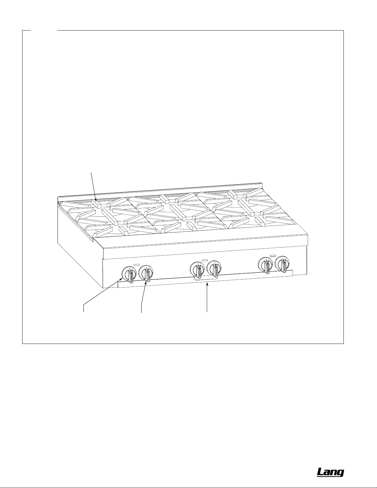
Figure 3
Operation of Open-Burner Sections
Each 12"-wide section has two control knobs. The left knob
controls the rear burner, while the right knob controls the
front burner. Each knob can be turned to OFF or to any
position in the range from LOW to HIGH.
To start cooking, turn the appropriate control knob to HIGH.
Visually check that the burner ignites. The gas does NOT
automatically shut off if the burner does not ignite! If the
burner does not ignite, check and/or light the pilots (see
procedure at right). When the burner is hot, the burner flame
should appear blue and steady (some slight yellowing of the
flame tips may occur when using propane gas).
While cooking, do not allow excessive drippings and/or
debris to accumulate on or below the burners. When
necessary, pull out and clean the drippings tray.
Burner Grate
(lifts out for cleaning)
When done cooking, turn the appropriate control knob to
OFF. (The pilot should remain lit).
Each burner has a pilot located beside the burner. To light a
pilot, do the following:
1. Check that the burner control knob is in the OFF position.
2. Check that the pilot is in the correct position beside the
burner.
3. Turn on the gas supply to the sectional range (if not
already on).
4. Light the pilot with a match or a pilot-lighting device. The
pilot flame should be blue and steady.
Rear-Burner
Control Knob
(OFF, HIGH-to-LOW)
Front-Burner
Control Knob
(OFF, HIGH-to-LOW)
Drippings Tray
(slides out for cleaning)
PAGE 10 OF 76 OWNER’S MANUAL 1192040 REV 1 (01/10)
Page 11
CHEF SERIES SECTIONAL RANGE OPERATION
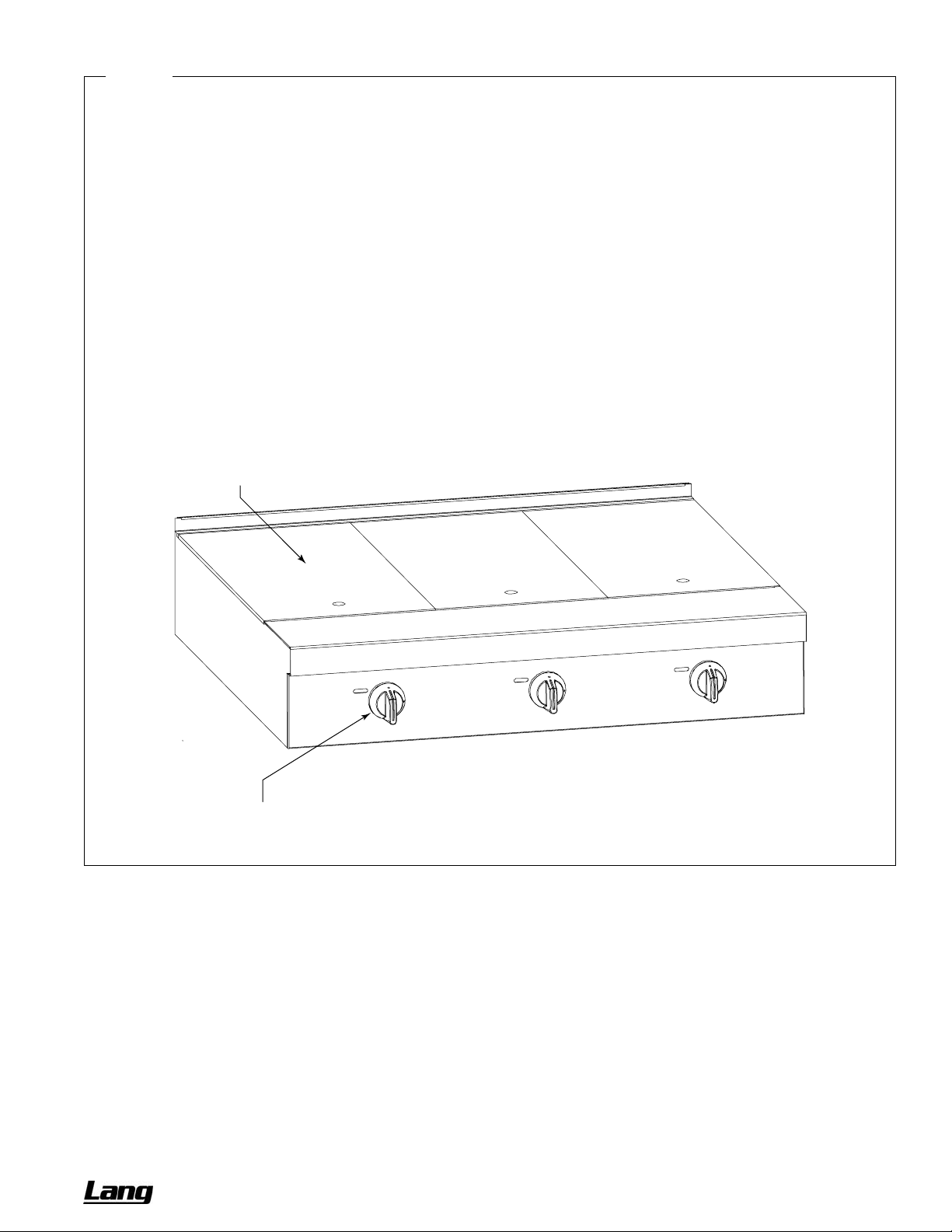
Figure 4
Operation of Uniform Hot-Top Section
Each 12”-wide section has one control knob, which can be
turned to OFF or to any position in the range from LOW to
HIGH. When the control is set to HIGH, the hot top surface
will heat to about 700°F (370°C).
To start cooking, turn the appropriate control knob to HIGH.
Visually check that the burner ignites.
automatically shut off if the burner does not ignite!
The gas does NOT
If the
burner does not ignite, check and/or light the pilots (see
procedure at right). When the burner is hot, the burner flame
should appear blue and steady (some slight yellowing of the
flame tips may occur when using propane gas).
Do not waste gas and abuse equipment by leaving the
burner on HIGH all the time.
certain electronic components may occur, and
YOUR WARRANTY
. During idle periods, turn the control to
Damage to the plates and
MAY VOID
LOW to keep the top warm.
Uniform HotTop Plate
(lifts out for cleaning
and lighting pilot)
When done cooking, turn the appropriate control knob to
OFF. (The pilot should remain lit).
Each 12”-wide section has two burners, each of which has a
pilot located near the front of the burner. To light the pilots,
do the following:
1. Check that the control knob is in the OFF position.
2. Lift up a hot-top section plate in order to expose the two
pilots.
3. Check that each pilot is in the correct position.
4. Turn on the gas supply to the sectional range (if not
already on).
5. Light the pilots with a match or a pilot-lighting device. The
pilot flames should be blue and steady.
Burner Control Knob
(OFF, HIGH-to-LOW)
OWNER’S MANUAL 1192040 REV 1 (01/10) PAGE 11 OF 76
Page 12
OPERATION CHEF SERIES SECTIONAL RANGE
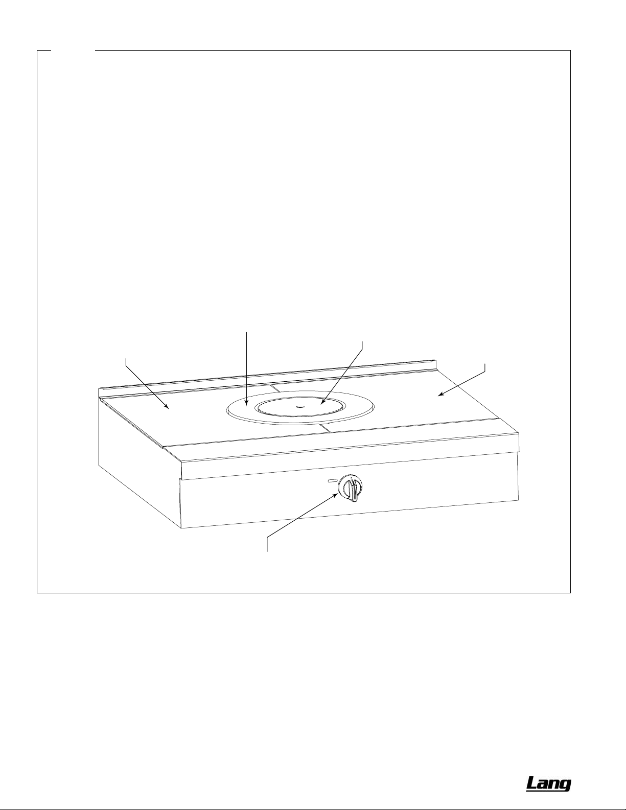
Figure 5
Operation of Graduated Hot-Top Section
Each section has one control knob, which can be turned to
OFF or to any position in the range from LOW to HIGH.
When the control is set to HIGH, the round center section will
heat to about 725°F (385°C), the ring-shaped section will
heat to about 625°F (330°C), and the outer areas will heat to
about 500°F (260°C).
To start cooking, turn the control knob to HIGH. Visually
check that the burner ignites.
automatically shut off if the burner does not ignite!
The gas does NOT
If the
burner does not ignite, check and/or light the pilots (see
procedure at right). When the burner is hot, the burner flame
should appear blue and steady (some slight yellowing of the
flame tips may occur when using propane gas).
Do not waste gas and abuse equipment by leaving the
burner on HIGH all the time.
certain electronic components may occur, and
YOUR WARRANTY
. During idle periods, turn the control to
Damage to the plates and
MAY VOID
LOW to keep the top warm.
When done cooking, turn the control knob to OFF. (The pilot
should remain lit).
Each section has one burner. The pilot is located adjacent to
the burner. To light the pilot, do the following:
1. Check that the control knob is in the OFF position.
2. Lift out the round center plate in order to expose the pilot.
3. Check that the pilot is in the correct position.
4. Turn on the gas supply to the sectional range (if not
already on).
5. Light the pilot with a match or a pilot-lighting device. The
pilot flame should be blue and steady.
Medium TemperatureArea
(plate lifts out for cleaning)
Lower Temperature Area
(plate lifts out for cleaning)
HighTemperature Area
(plate lifts out for cleaning
and lighting pilot)
Lower TemperatureArea
(plate lifts out for cleaning)
Burner Control Knob
(OFF, HIGH-to-LOW)
PAGE 12 OF 76 OWNER’S MANUAL 1192040 REV 1 (01/10)
Page 13
CHEF SERIES SECTIONAL RANGE OPERATION
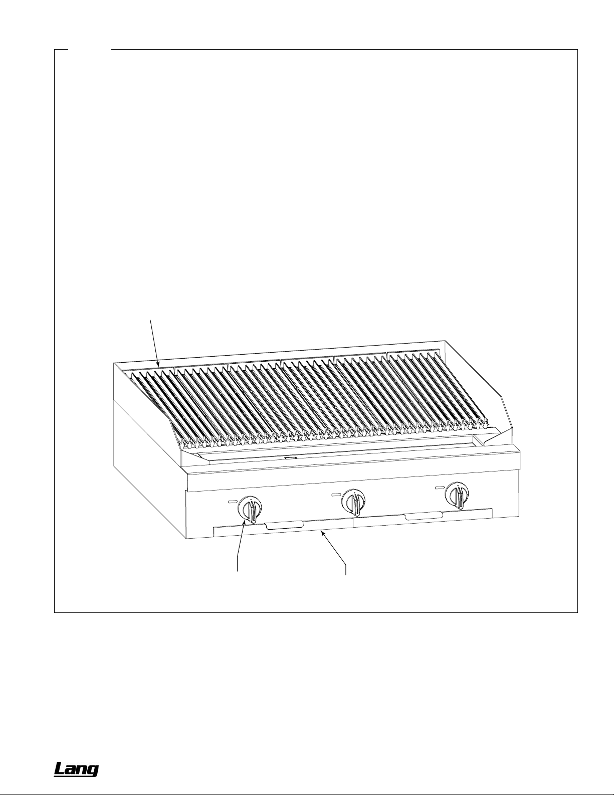
Figure 6
Operation of Charbroiler Section
Each 12”-wide section has one control knob, which can be
turned to OFF, HIGH, or LOW. Each burner top-grate can be
turned over to provide either wide branding marks or
narrower branding marks with channels to carry away
drippings (and so reduce flare up). The back-to-front slope of
each top-grate is adjusted by positioning the back end of the
top-grate on either the lower or the higher grate-support rail.
The radiants (just above the burners) can be reversed frontand-back to provide higher heat toward the back than the
front, or vice versa. “Lava rock” briquettes can be placed on
grates located above the radiants.
To start cooking, turn the appropriate control knob to HIGH.
Visually check that the burner ignites.
automatically shut off if the burner does not ignite!
The gas does NOT
If the
burner does not ignite, check and/or light the pilots (see
procedure at right). When the burner is hot, the burner flame
should appear blue and steady (some slight yellowing of the
flame tips may occur when using propane gas).
Grates
(lift out for cleaning)
When done cooking, turn the appropriate control knob to
OFF. (The pilot should remain lit).
Each 12”-wide section has two burners, each of which has a
pilot located near the front of the burner. To light the pilots,
do the following:
1. Check that the burner control knob is in the OFF position.
2. Lift up a grate in order to expose the two pilots. They are
accessible through a slot near the front end of the radiant
plate.
3. Check that each pilot is in the correct position.
4. Turn on the gas supply to the sectional range (if not
already on).
5. Light the pilots with a match or a pilot-lighting device. The
pilot flames should be blue and steady.
Burner Control Knob
(OFF, HIGH, or LOW)
Drippings Tray
(slides out for cleaning)
OWNER’S MANUAL 1192040 REV 1 (01/10) PAGE 13 OF 76
Page 14
OPERATION CHEF SERIES SECTIONAL RANGE
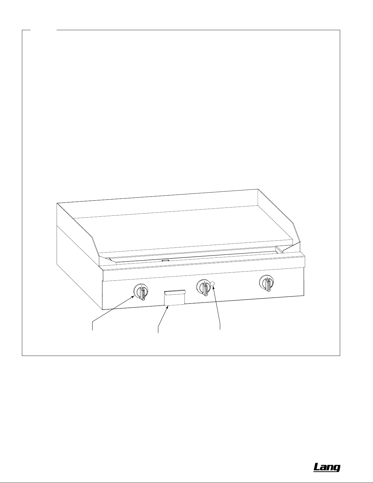
Figure 7
Operation of Standard (Non-Thermostatic) Griddle Sections
Each 12”-wide section has one control knob, which can be
turned to OFF, HIGH, or LOW.
To start cooking, turn the appropriate control knob to HIGH.
Check that the burner ignites.
automatically shut off if the burner does not ignite!
The gas does NOT
If the
burner does not ignite, check and/or light the pilots (see
procedure at right). When the burner is hot, the burner flame
should appear blue and steady (some slight yellowing of the
flame tips may occur when using propane gas).
Always remember to heat the griddle slowly because quick
heating may cause costly damage. Never place utensils on
the griddle.
Do not waste gas and abuse equipment by leaving the
griddle on HIGH all the time.
certain electronic components may occur, and
YOUR WARRANTY
. During idle periods, turn the control to
Damage to the griddle and
MAY VOID
LOW to keep the griddle warm. (Do not allow the griddle to
overheat above 550°F (288°C), as this will cause warping or
breakage.)
When necessary while cooking, pull out and empty the
grease drawer.
When done cooking, turn the appropriate control knob to
OFF. (The pilot should remain lit).
Each griddle section has a single pilot that is lit using a long
match inserted thorough a hole in the front valve panel. (A
48"-wide griddle has two pilots.) To light the pilot, do the
following:
1. Check that all the control knobs are in the OFF position.
2. Turn on the gas supply to the sectional range (if not
already on).
3. Light the pilot by inserting a long match (at least 11" long)
or pilot-lighting device straight into the hole on the front
valve panel of the griddle.
Burner Control Knob
(OFF, HIGH, or LOW)
Grease Drawer
(slides out for cleaning)
Pilot-Lighting
Opening
PAGE 14 OF 76 OWNER’S MANUAL 1192040 REV 1 (01/10)
Page 15
CHEF SERIES SECTIONAL RANGE OPERATION
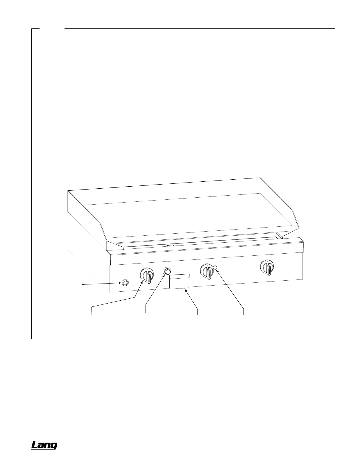
Figure 8
Operation of Thermostatic Griddle Sections
Each 12”-wide section has one control knob that can be
turned to OFF, or to any temperature in the range 150°F to
400°F (66°C to 204°C).
To start cooking, turn on the appropriate control knob. Check
that the burner ignites. If the burner does not ignite, check
and/or light the pilots (see procedure at right).
Never place utensils on the griddle.
Do not waste gas and abuse equipment by leaving the
griddle set at a high temperature all the time.
Damage to
the griddle and certain electronic components may occur,
and
MAY VOID YOUR WARRANTY. During idle periods,
turn the control to a low temperature to keep the griddle
warm. (Do not allow the griddle to overheat above 550°F
(288°C), as this will cause warping or breakage.)
When necessary while cooking, pull out and empty the
grease drawer.
When done cooking, turn the appropriate control knob to
OFF. (The pilot should remain lit).
Each griddle section has a single pilot that is lit using a long
match inserted thorough a hole in the front valve panel. (A
48"-wide griddle has two pilots.) To light the pilot, do the
following:
1. Check that all control knobs are in the OFF position.
2. Turn on the gas supply to the sectional range (if not
already on).
3. Turn on the Griddle Gas Shut-Off Valve (if not already
on).
4. Press and hold in the Safety Switch Button.
5. Light the pilot by inserting a long match (at least 11" long)
or pilot-lighting device straight into the hole on the front
valve panel of the griddle.
6. After about a minute, release the Safety Switch Button.
The pilot should remain lit.
Safety
Switch
Button
Burner Control Knob
(OFF, temperature)
Griddle Gas
Shut-Off Valve
Grease Drawer
(slides out for cleaning)
Pilot-Lighting
Opening
OWNER’S MANUAL 1192040 REV 1 (01/10) PAGE 15 OF 76
Page 16
OPERATION CHEF SERIES SECTIONAL RANGE
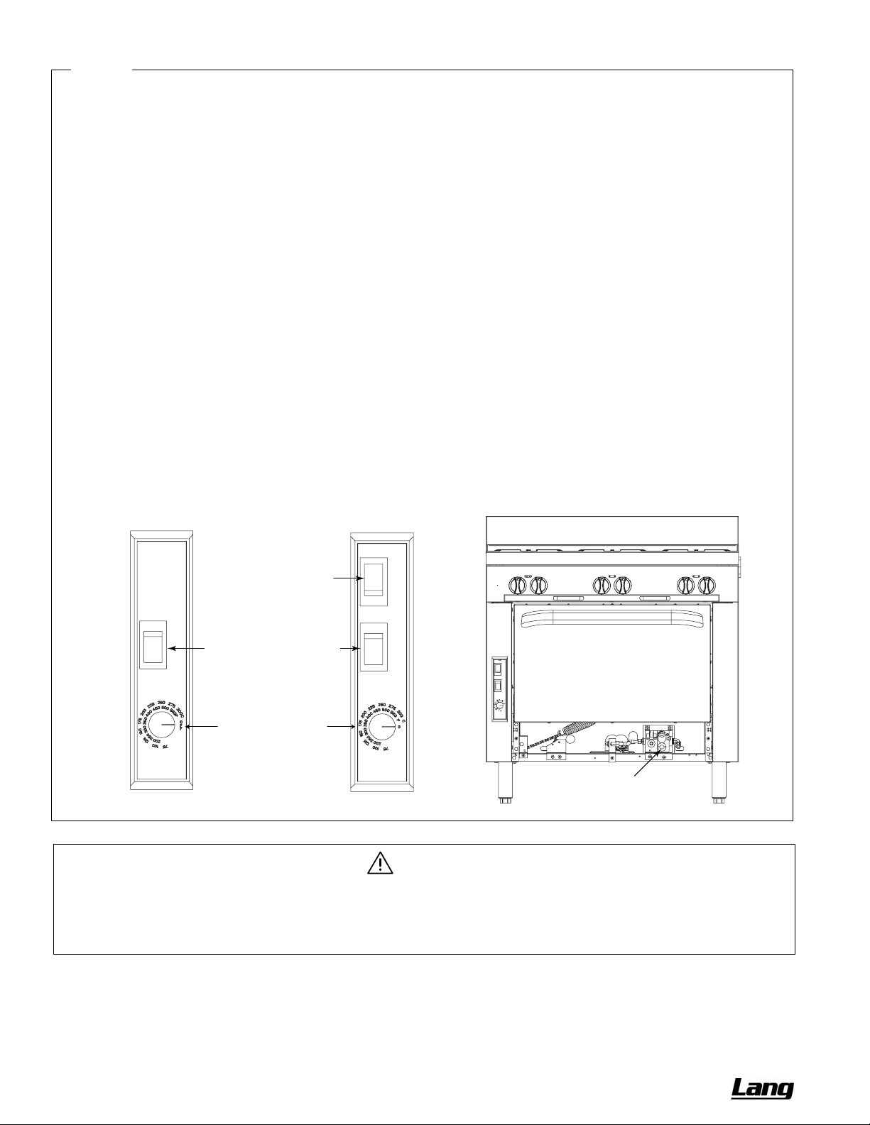
Figure 9
Operation of Oven
Each oven has a thermostatic control that can be set in the
range 175°F to 550°F (66°C to 260°C). Convection ovens
have a fan that can be set to HI speed or LO speed.
While cooking, if the door is opened on a convection oven,
the fan and heat will temporarily stop until the door is closed.
Do not allow excessive drippings and/or debris to
accumulate on the interior of the oven. When necessary, pull
out and clean the oven-bottom tray.
To light and start cooking, do the following:
FOR UNITS WITH A STANDING PILOT
1. Open kick panel and locate knob on valve assembly.
2. Turn the knob to PILOT and press inward. While holding
the knob inward, light the pilot with an appropriate lighter.
3. Hold knob in the inward position for 30 seconds and
release. The pilot should remain lit.
4. Turn the knob to ON and close kick panel.
5. Select on the thermostat the cooking temperature
appropriate for the food to be cooked.
6. For convection ovens, select the fan speed appropriate
for the food to be cooked.
FOR UNITS WITH ELECTRONIC IGNITION
1. Set the Oven Power Switch to ON. The pilot will light
automatically. (You will hear a “snapping” sound until the
pilot ignites.)
2. Select on the thermostat the cooking temperature
appropriate for the food to be cooked.
3. For convection ovens, select the fan speed appropriate
for the food to be cooked.
When done cooking, turn the Oven Power Switch to OFF.
Controls for Ovens
with Standing Pilot
Oven Power Switch
Fan-Speed Switch
(for Convection Ovens)
Oven Thermostat
Controls for Ovens
with Electronic Ignition
WARNING
PILOT-ON Knob
THE USE OF ALUMINUM FOIL CAN CAUSE HEAT DISTRIBUTION PROBLEMS IN OVENS. EXTREME
CARE MUST BE USED WHEN PLACING ALUMINUM FOIL IN THE OVEN TO ENSURE THAT IT DOES NOT
BLOCK OR CHANGE THE AIR FLOW. THE USE OF ALUMINUM FOIL MAY VOID THE PRODUCT
WARRANTY IF ITS USE IS ASCERTAINED TO BE A PROBLEM.
PAGE 16 OF 76 OWNER’S MANUAL 1192040 REV 1 (01/10)
Page 17
CHEF SERIES SECTIONAL RANGE CLEANING & MAINTENANCE
CLEANING & MAINTENANCE
WARNING
Shut off the gas supply to the appliance before cleaning or performing maintenance on any gas appliance.
The appliance may be equipped with a restraint device to limit its movement in order to prevent damage to the
gas connection. If disconnection of this restraint is necessary to move the appliance for cleaning or
maintenance, reconnect the restraint when the appliance is moved back to its original installed position.
Lang appliances are sturdily constructed of the best materials and are designed to provide du rable service when
treated with ordinary care. To expect the best performance, your equipment must be maintained in good condition and
cleaned daily. Naturally, the periods for this care and cleaning depend on the amount and degree of usag e.
Following daily and periodic maintenance procedures will enhance long life for your equipm ent. Climatic conditions
(such as salt air) may require more thorough and frequent cleaning or the life of the equi pment could be adversely
affected.
Keep exposed, cleanable areas clean at all times.
DAILY CLEANING AND MAINTENANCE
The daily cleaning procedure is as follows:
1. Shut off the main gas supply and allow the sectional range to cool.
2. Pull out, empty, and clean all drippings trays and grease drawers.
3. Remove and clean all oven racks and oven-bottom trays. Wipe clean the interior of the oven.
4. Visually check for any food and/or debris that may have fallen down into the burner areas.
5. Wipe clean all exterior surfaces.
6. Replace the cleaned and dried drippings trays, grease drawers, and oven components.
7. Check that nothing has been left on or near the sectional range that might block the entry of combustion air or
the escape of combustion exhaust.
MONTHLY CLEANING AND MAINTENANCE
The following tasks should be performed monthly:
1. Clean around burner air mixers and orifices if lint has accumulated in these areas.
2. Check for proper pilot operation. Check that the pilot flames are blue (with little or no yellow in the flame tips),
stable (not lifting off the pilots), and not producing carbon. If adjustment is necessary, call for service.
3. Check for proper burner operation. The burner flames should be blue and stable. If adjustment is necessary, call
for service.
SEMIANNUAL CLEANING AND MAINTENANCE
At least twice a year the venting system should be examined and cleaned.
STAINLESS-STEEL SURFACES
To remove normal dirt, grease and product residue from stainless steel surfaces that operate at LOW temperature,
use ordinary soap and water (with or without detergent) applied with a sponge or cloth. Dry thoroughly with a clean
cloth.
To remove BAKED-ON grease and food splatter, or condensed vapors; apply cleanser to a damp cloth or sponge and
rub cleanser on the metal in the direction of the polishing lines on the metal. Rubbing cleanser, as gently as possible,
in the direction of the polished lines will not mar the finish of the stainless steel. NEVER RUB WITH A CIRCULAR
MOTION. Soil and burnt deposits which do not respond to the above procedure can usually be removed by rubbing
the surface with SCOTCH-BRITE scouring pads or STAINLESS scouring pads. DO NOT USE ORDINARY STEEL
OWNER’S MANUAL 1192040 REV 1 (01/10) PAGE 17 OF 76
Page 18
CLEANING & MAINTENANCE CHEF SERIES SECTIONAL RANGE
WOOL as any particles left on the surface will rust and further spoil the appearance of the finish. NEVER USE A
WIRE BRUSH, STEEL SCOURING PADS (EXCEPT STAINLESS), SCRAPER, FILE OR OTHER STEEL TOOLS.
Surfaces which are marred collect dirt more rapidly and become more difficult to clean. Marring also increases the
possibility of corrosive attack. Refinishing may then be required.
“Heat tint” is darkened areas that sometimes appear on stainless steel surfaces where the area has been subjected to
excessive heat. These darkened areas are caused by thickening of the protectiv e surfa ce of t he stainless steel and
are not harmful. Heat tint can normally be removed by the foregoing, but tint which does not respond to this procedure
calls for a vigorous scouring in the direction of the polish lines using SCOTCH-BRITE scouring pads or a STAINLESS
scouring pad in combination with a powered cleanser. Heat tint may be lessened by reducing heat to equipment
during slack periods.
BAKED-ENAMEL SURFACES
Allow appliance to cool somewhat after use and wash baked-enamel surfaces with a hot, mild detergent or soap
solution. In particular, clean off all grease deposits. Dry thoroughly with a dry cloth.
OPEN-BURNERS AND GRATES
The grates can be removed and cleaned with a solution of hot water and strong soap or detergent. The burners
themselves require little attention, but if spillage should occur, it may be necessary to clean around pilot areas, air
mixer and under burners. Use a wire brush if necessary. Periodically, open-burners sho uld be removed and cleaned.
Allow the interior of the burner to drain, and dry thoroughly before replacing.
HOT-TOP SURFACES
Before cleaning hot-top surfaces, allow them to cool. If water is used on hot-tops while they are still hot, they may
crack, so avoid this practice. The hot-top plates can be removed and cleaned with hot water and detergent. A wire
brush may be used on the underside of the hot top plate. It is recommended not to clean tops while still on the range,
even if cooled, as excess water will drip into the burner box and deteriorate the metal.
CARE OF GRIDDLES
A griddle should be carefully cared for in order to avoid possible damage. (The griddle should have been tempered as
part of the installation procedure, see page
any type of steel wool. Small particles may be left on the surface and get into food products. Do not clean spatula by
hitting the edge on the griddle plate. Such action will only cut and pit the griddle plate, leaving it rough and hard to
clean.
27). Use a Norton Alundum Griddle Brick to clean the griddle. Do not use
OVEN INTERIOR
WARNING
FOR YOUR SAFETY, DISCONNECT THE POWER SUPPLY TO THE SECTIONAL RANGE BEFORE
CLEANING THE OVEN. WHEN CLEANING THE BLOWER WHEEL OF A CONVECTION OVEN, BE SURE TO
HAVE THE POWER SWITCH IN THE “OFF” POSITION.
To clean the oven interior, first allow the oven to cool. Remove oven bottom and clean it by rubbing with strong
detergent and a Brillo pad or similar scrubber. “Spillovers” should be cleaned from the bottom as soon as possible to
prevent carbonizing and a “burnt-on” condition. For stubborn accumulations, commercial oven clea ners are
recommended.
The porcelain oven door lining can be cleaned in a similar manner. The side, rear and top lining should be wiped only
with a cloth dampened with a mild detergent and water. Avoid using excessive amounts of water, as this may drip into
burner compartment and deteriorate the metal in that area. Do not use strong commercial cleaners or abrasive pads
on the side, rear or top linings, as they may damage the finish or leave gray residue.
PAGE 18 OF 76 OWNER’S MANUAL 1192040 REV 1 (01/10)
Page 19
CHEF SERIES SECTIONAL RANGE INSTALLATION
INSTALLATION
NOTICE
These installation procedures must be followed by qualified personnel or warranty will be void.
Local codes regarding installation vary greatly from one area to another. The National Fire Protection Association,
Inc., states in its NFPA 96 latest edition that local codes are the “authority having jurisdiction” when it comes to
installation requirements for equipment. Therefore, installations should comply with all local codes.
The installation must conform with local codes, or in the absence of local codes, with the National Fuel Gas Code,
ANSI Z223.1, Natural Gas Installation Code, CAN/CGA-B149.1, or the Propane Installation Code CAN/CGA-
B149.2, as applicable, including:
1. The appliance and its individual shutoff valve must be disconnected from the gas supply piping system during
any pressure testing of that system at test pressures in excess of 1/2 psi (3.45 kPa).
2. The appliance must be isolated from the gas supply piping system by closing its individual manual shutoff valve
during any pressure testing of the gas supply piping system at test pressures equal to or less than 1/2 psi (3.45
kPa).
NOTICE
EXHAUST FANS AND CANOPIES: It is recommended that the range be installed under a ventilation hood.
Consult local codes for proper installation of hoods. Proper ventilation is the owner’s responsibility. Any problem
due to improper ventilation will not be covered by warranty.
NOTICE
In the Commonwealth of Massachusetts all gas appliances vented by either mechanical systems or ventilation
hoods shall comply with 248 CMR interlocking requirements.
This installation procedure does NOT cover sectional fryers, fryer filter systems, salamander b roile rs, upright broilers,
cheese melters, or refrigerated bases. Consult the manuals of those appliances when they are being installed as part
of a sectional range battery.
STEP 1: UNPACKING
IMMEDIATELY INSPECT FOR SHIPPING DAMAGE
All containers should be examined for damage before and during unloading. The freight carrier has assumed
responsibility for its safe transit and delivery. If damaged equipment is received, either apparent or concealed, a
claim must be made with the delivering carrier.
Apparent damage or loss must be noted on the freight bill at the time of delivery. The freight bill must then be
signed by the carrier representative (Driver). If the bill is not signed, the carrier may refuse the claim. The carrier
can supply the necessary forms.
A request for inspection must be made to the carrier within 15 days if there is concealed damage or loss that is not
apparent until after the equipment is uncrated. The carrier should arrange an inspection. Be certain to hold all
contents plus all packing material.
For each section, do the following:
1. Cut the banding straps and remove the corrugated cardboard surrounding the section. (If legs, casters, a flue
riser, and/or shelf components were shipped in the same container, set them aside for installation in later steps
of this procedure. Do not remove any tags or labels attached to the range until the range is installed and working
properly.
OWNER’S MANUAL 1192040 REV 1 (01/10) PAGE 19 OF 76
Page 20
INSTALLATION CHEF SERIES SECTIONAL RANGE
2. Cut the banding strap holding the range to the wooden skid.
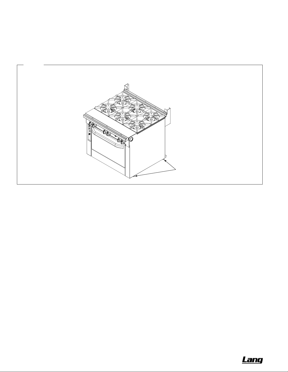
3. Unbolt the shipping hold-down brackets from the skid, then remove the brackets from the appliance (see
Figure
10).
4. If the range is to be installed on 6" legs, go to Step 2a.
If the range is to be installed on 6" casters, go to Step 2b.
If the range is to be installed on a caster-frame, go to Step 2c.
Figure 10
Removal of Shipping Hold-Down Brackets
Shipping
Hold-Down
Brackets
STEP 2A: ATTACH LEGS TO THE RANGE
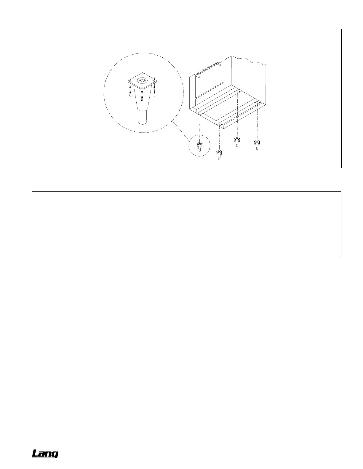
A set of four legs is packed with units ordered with legs. (For units ordered with casters, go to Step 2b.)
A threaded leg pad is fastened to the base frame at each corner. Each leg has a correspondin g mating thread. The
legs can be adjusted to overcome a slightly uneven floor.
1. Raise the range sufficiently to allow the legs to be attached. For safety, “shore up” and support the range with an
adequate blocking arrangement strong enough to support the load.
2. Screw the legs into the holes in the centers of the leg pads (see
3. Lower the range gently onto a level surface. Never drop or allow the range to fall.
4. Go on to Installation Step 4.
Figure 11).
PAGE 20 OF 76 OWNER’S MANUAL 1192040 REV 1 (01/10)
Page 21
CHEF SERIES SECTIONAL RANGE INSTALLATION
Figure 11
Installation of Legs
STEP 2B: ATTACH CASTERS TO THE RANGE
NOTICE
For an appliance equipped with casters, (1) the installation shall be made with a connector that complies with the
Standard for Connectors for Movable Gas Appliances, ANSI Z21.69 or Connectors for Moveable Gas Appliances,
CAN/CGA-6.16, and a quick-disconnect device that complies with the Standard for Quick-Disconnect Devices for
Use With Gas Fuel, ANSI Z21.41, or Quick Disconnect Devices for Use with Gas Fuel, CAN1-6.9, (2) adequate
means must be provided to limit the movement of the appliance without depending on the connector and the
quick-disconnect device or its associated piping to limit the appliance movement and (3) the restraining means
should be attached to a frame member on the back of the unit.
A set of four casters is packed with units ordered with casters (instead of legs).
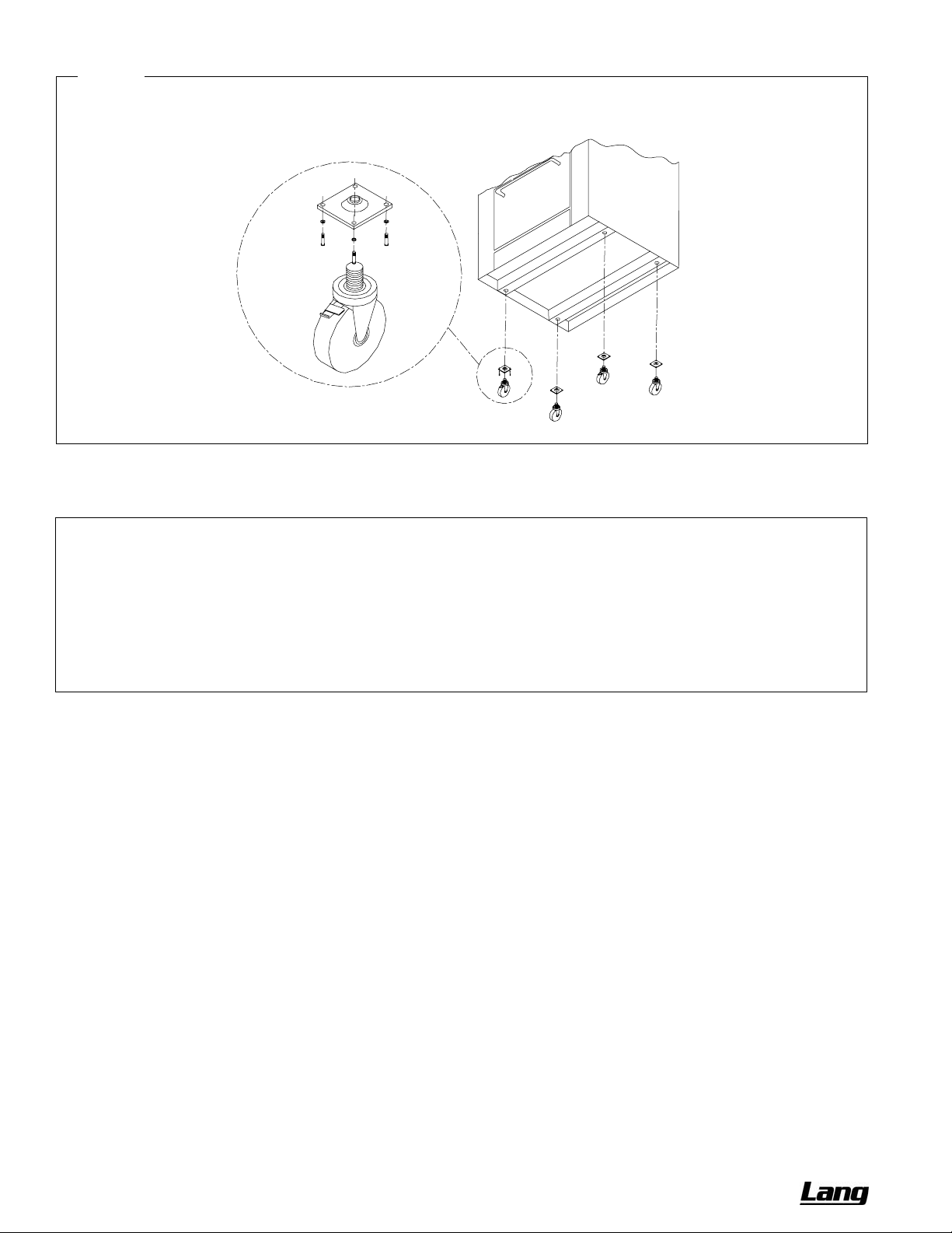
A threaded leg pad is fastened to the base frame at each corner. Each caster has a corresponding mating thread. The
casters can be adjusted to overcome a slightly uneven floor. Casters are provided with a fitting for proper lubrication
when required.
1. Raise unit sufficiently to allow the casters to be attached. For safety, “shore up” and support the range with an
adequate blocking arrangement strong enough to support the load.
2. Screw the casters into the holes in the centers of the leg pads (see
locking brake under the front of the range.
3. Lower the range gently onto a level surface. Never drop or allow the range to fall.
4. Go to Installation Step 3.
Figure 12). Install the casters that have a
OWNER’S MANUAL 1192040 REV 1 (01/10) PAGE 21 OF 76
Page 22
INSTALLATION CHEF SERIES SECTIONAL RANGE
Figure 12
Installation of Casters
1
STEP 2C: MOUNT RANGE ON CASTER FRAME
NOTICE
For an appliance equipped with casters, (1) the installation shall be made with a connector that complies with the
Standard for Connectors for Movable Gas Appliances, ANSI Z21.69 or Connectors for Moveable Gas Appliances,
CAN/CGA-6.16, and a quick-disconnect device that complies with the Standard for Quick-Disconnect Devices for
Use With Gas Fuel, ANSI Z21.41, or Quick Disconnect Devices for Use with Gas Fuel, CAN1-6.9, (2) adequate
means must be provided to limit the movement of the appliance without depending on the connector and the
quick-disconnect device or its associated piping to limit the appliance movement and (3) the restraining means
should be attached to a frame member on the back of the unit.
The range can be mounted on an optional caster frame. The frame will have a threaded leg pad at each corner. Each
caster has a corresponding mating thread. The casters can be adjusted to overcome a slightly uneven floor. Casters
are provided with a fitting for proper lubrication when required.
1. Assemble the caster frame components.
2. Screw the casters into the holes in the centers of the leg pads of the caster frame. Install the casters that have a
locking brake under the front of the battery.
3. Lower the caster frame gently onto a level surface. Never drop or allow the frame to fall.
4. Block and brace the frame so that it will not move while the battery sections are installed on it.
5. Lift and gently place the range in position on the caster frame. Never drop or allow the range to fall.
6. Bolt the range to the caster frame.
7. Go to Installation Step 3.
PAGE 22 OF 76 OWNER’S MANUAL 1192040 REV 1 (01/10)
Page 23

CHEF SERIES SECTIONAL RANGE INSTALLATION
STEP 3: ATTACH RESTRAINT TO RANGE (OR BATTERY) MOUNTED ON CASTERS
NOTICE
For an appliance equipped with casters, (1) the installation shall be made with a connector that complies with the
Standard for Connectors for Movable Gas Appliances, ANSI Z21.69 or Connectors for Moveable Gas Appliances,
CAN/CGA-6.16, and a quick-disconnect device that complies with the Standard for Quick-Disconnect Devices for
Use With Gas Fuel, ANSI Z21.41, or Quick Disconnect Devices for Use with Gas Fuel, CAN1-6.9, (2) adequate
means must be provided to limit the movement of the appliance without depending on the connector and the
quick-disconnect device or its associated piping to limit the appliance movement and (3) the restraining means
should be attached to a frame member on the back of the unit.
Install the restraint cable to a range (or battery) mounted on casters using the following procedure:
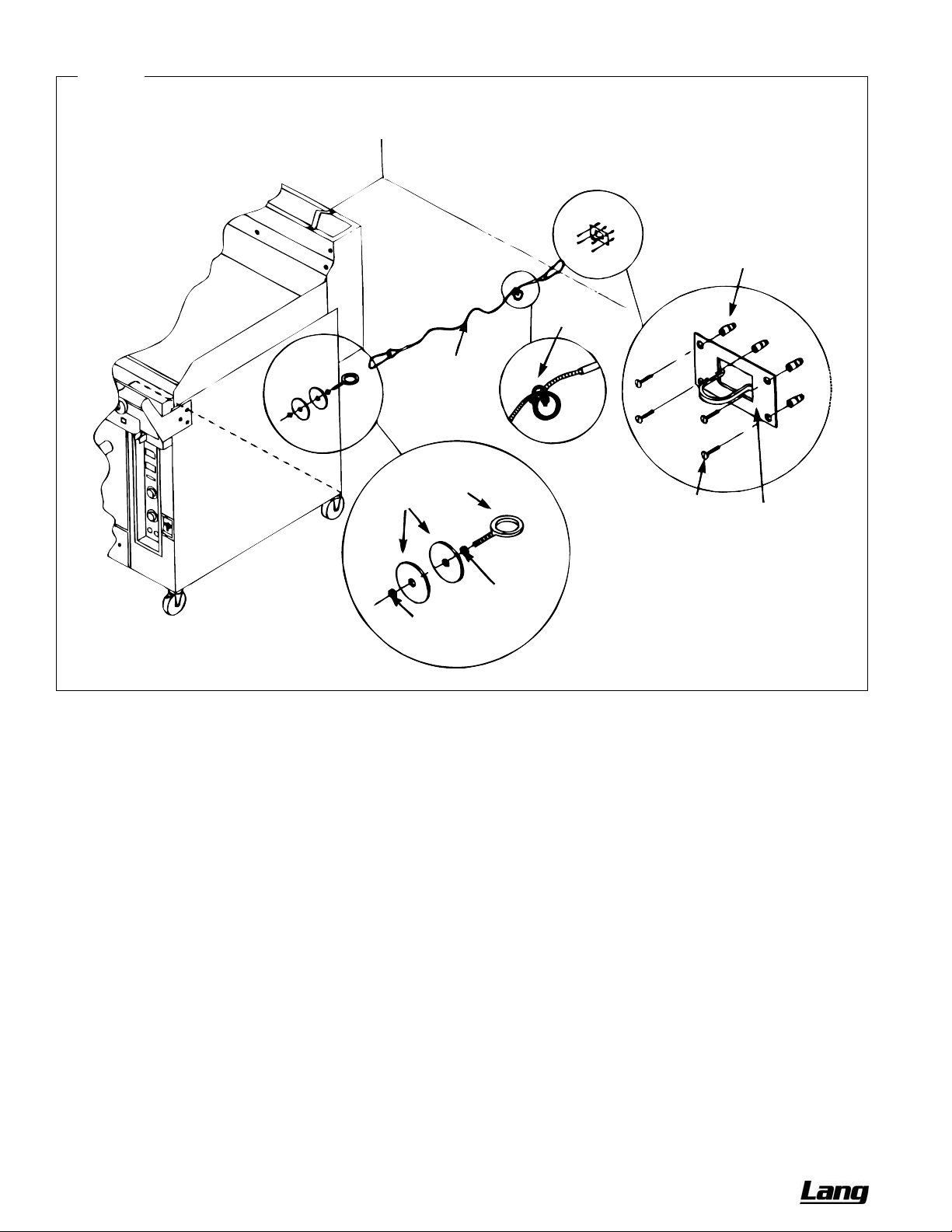
1. Secure the restraining-device bracket (item “B” in
appliance connector inlet and outlet connections. Use four #12 screws (items “C”) and plastic anchors (items “A”)
if necessary.
2. Install eye-bolt (item “F”) to a frame member on the rear of the equipment. After checking carefully behind the
frame member for adequate clearance, drill a 1/4" hole through the frame member.
3. Thread hex nut (item “G”) and slide the washer (item “H”) onto the eye-bolt. Insert the eye-bolt through the 1/4"
drilled hole and secure with a washer (item “H”) and nylon lock nut (item “I”).
4. Using the spring-loaded snap hooks, attach the restraining device to the bracket and the eye-bolt.
5. Using the cable clamp (item “D”), adjust the restraining device extended length to prevent over-bending or
kinking of the appliance connector.
For units not equipped with flame safety devices, be sure all valves are turned off prior to disconnecting. After
reconnecting, be sure all control knobs are turned off and all pilots are lit.
Figure 13) to a wall stud located as close as possible to the
NOTICE
Adequate means must be provided to limit the movement of the appliance without depending on the connector and
the quick-disconnect device or its associated piping to limit the appliance movement.
The restraining means should be attached to a frame member on the back of the unit.
OWNER’S MANUAL 1192040 REV 1 (01/10) PAGE 23 OF 76
Page 24
INSTALLATION CHEF SERIES SECTIONAL RANGE
Figure 13
Installation of Cable Restraint
A
D
E
H
F
C
G
I
B
STEP 4: CONNECT BATTERY SECTIONS
If the range is part of a battery, and the battery was shipped partially disassembled, connect the battery sections using
the following procedure.
1. Remove valve panels from all sections. Mark them so that they can be returned to their respective section.
2. Position the center section of the battery and carefully level that unit. Use a long spirit level four ways; across
front top rail and the rear edge, and along each side edge.
3. If not already in place, attach pipe-union to front manifold of the battery. Screw it in far enough to be able to slide
the adjacent section into position.
4. Bring up adjacent section and level it using the same method and by using the center unit as reference. Match
front rails and rear edge. When a battery is set on a masonry base and legs are not used, shims may be used.
Special attention should be given to griddle ranges to allow proper drainage.
5. Bolt the frames of the sections together.
6. Connect the front manifolds using the pipe-union.
7. Attach the trim-strip between the section tops.
8. Install the continuous front-rail, if ordered.
9. Slide control knobs onto their shafts (to operate the sections during the installation procedure), but do not yet
reattach valve panels or front-panel trim pieces.
PAGE 24 OF 76 OWNER’S MANUAL 1192040 REV 1 (01/10)
Page 25
CHEF SERIES SECTIONAL RANGE INSTALLATION
STEP 5: ATTACH FLUE RISER AND SHELF ASSEMBLIES
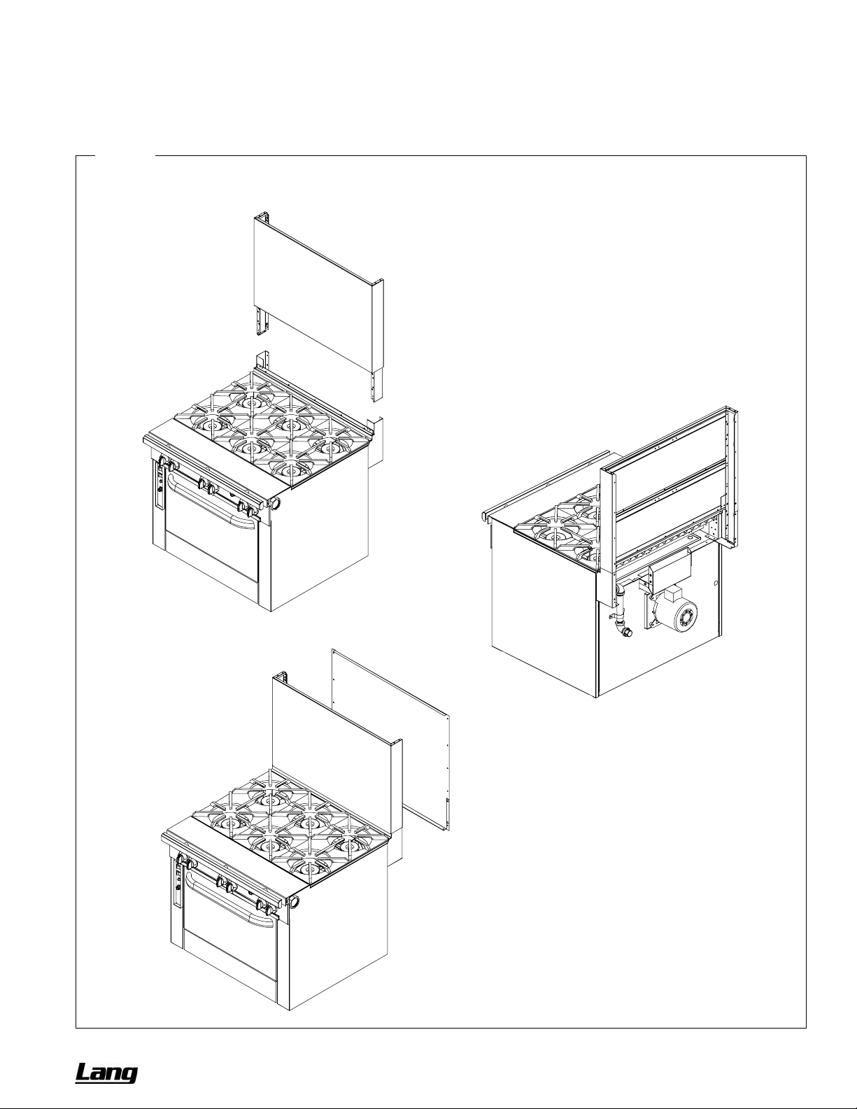
Install the flue riser(s) using the following procedure (as shown in Figure 14).
1. Attach any salamander broilers and flue-riser-mounted cheese melters to appropriate sections following the
installation procedure in the manuals for those options.
Figure 14
Installation of Flue Riser
Slide the front of the flue riser down into
the brackets on the sectional range.
Secure the flue riser to the brackets using
the provided fasteners. Also secure the
bottom edge of the flue riser to the top
rear edge of the sectional range.
Attach the rear of the flue riser to the front of
the flue riser using the provided fasteners.
OWNER’S MANUAL 1192040 REV 1 (01/10) PAGE 25 OF 76
Page 26

INSTALLATION CHEF SERIES SECTIONAL RANGE
2. Slide each flue riser down onto the brackets projecting from the back of the corresponding section(s) of the
sectional range. Secure the flue riser to the brackets with the four provided 1/4-20x3/4 hex-head bolts, flat
washers, and lockwashers. Also, secure the bottom edge of the flue riser to the top rear edge of the sectional
range using the provided #10 sheet metal screws.
3. If access to the interior of the flue riser is necessary to make gas connections, make those connections at this
time.
4. Attach each wall shield to the back of the corresponding flue riser using the provided #10 sheet metal screws.
5. Connect the top side edges of adjoining flue risers using the provided small plates and screws.
6. If tubed shelves were installed, place the tubes in place in the shelf brackets.
7. If sloped enclosures were ordered (for flue-mounted salamander broilers and/or cheese melters), install them at
this time.
STEP 6: CONNECT ELECTRICITY (FOR SECTIONS WITH OVEN-BASES)
A wiring diagram is located behind the kick panel of the oven-base ranges. Be sure that the input voltage and phase
match the requirements shown on the serial plate.
Oven-base ranges ordered with a 115V, 60Hz, single-phase electrical rating are factory-supplied with a three-wire
cord with a three-prong plug that fits any standard three-prong grounded receptacle. Each standard oven requires a
15 ampere supply, while each convection oven requires a 20 ampere supply.
Oven-base ranges ordered with a 208/236V, 60Hz, single- or three-phase electrical rating are factory-equipped with
a two-pole terminal block located behind cover plate located on the rear of the unit. To connect the supply wires,
remove the cover plate. Route the supply wires and the grounding wire through the strain relief fitting to the terminal
block. Insert the supply wires, one each, into the two poles of the terminal block and tighten the screws. Insert the
ground wire into the grounding lug and tighten the screw. Re-attach the cover plate.
Three phase units are wired as above, using only two supply wires. The third wire is not use d and must be properly
terminated.
All units are shipped wired as specified by factory order. Conversion between single-pha se and three-phase can be
accomplished by referring to phase loading and line amperes chart on the wiring diagram for wire size and ampere
requirements.
STEP 7: CONNECT GAS SUPPLY
If the sectional range is being installed at over 2,000 feet altitude and that information was not specified when
ordered, contact the appropriate authorized Lang Service Representative or the Lang Service Department. Failure to
install with proper orifice sizing will result in poor performance and may void the warranty.
The sectional range is design-certified for operation on natural or propa ne gases. The sectional range is shipped
configured and adjusted for the type of gas specified by the purchaser, which is indicated on the serial plate (see
Figure 1 on page 3). Connect the sectional range ONLY to the type of gas for which it is configured and adjusted.
Minimum supply pressure is 7" W.C. for natural gas, 11" W.C. for propane. An external pressure regulator and shut off
valve are provided. If using a flexible-hose gas connection, the I.D. of the hose must not be smaller than the
connector on the sectional range, and must comply with ANSI Z21.69. Provide an adequate m eans of restraint to
prevent undue strain on the gas connection.
If applicable, the vent line from the gas pressure regulator shall be installed to the outdoors in accordance with local
codes, or in the absence of local codes, with the National Fuel Gas Code, ANSI Z223.1, Natural Gas Installation
Code, CAN/CGA-B149.1, or the Propane Installation Code CAN/CGA-B149.2, as applicable.
An adequate gas supply is imperative. Undersized or low pressure lines will restrict the volume of gas required for
satisfactory performance. A 1/8" pressure tap is located on the manifold to measure the manifold pressure. The
supply line to the sectional range should be no smaller than the inside diameter of the pipe on the se ctional range to
which it is connected.
CAUTION
ALL PIPE JOINTS AND CONNECTIONS MUST BE TESTED THOROUGHLY FOR GAS LEAKS. USE ONLY
SOAPY WATER FOR TESTING ON ALL GASES. NEVER USE AN OPEN FLAME TO CHECK FOR GAS LEAKS.
ALL CONNECTIONS MUST BE CHECKED FOR LEAKS AFTER THE APPLIANCE HAS BEEN PUT INTO
OPERATION. TEST PRESSURE SHOULD NOT EXCEED 14" W.C.
PAGE 26 OF 76 OWNER’S MANUAL 1192040 REV 1 (01/10)
Page 27

CHEF SERIES SECTIONAL RANGE INSTALLATION
Do the following to connect the gas supply:
1. Check that all control knobs on the sectional range are in the OFF position.
2. Purge the gas supply line to clean out dust, dirt, or other foreign matter before connecting the line to the sectional
range.
3. The gas connection piping may have been partially installed at the factory. If necessary, attach the gas
connection of any appliances mounted on a flue riser.
4. Locate the pressure regulator(s) packed with the sectional range. Install the pressure regulator, taking care that
the direction of gas flow corresponds to the arrow on the side of the pressure regulator.
CAUTION
HOLD THE PRESSURE REGULATOR WITH A WRENCH WHEN TIGHTENING THE CONNECTION TO THE
SUPPLY PIPE TO AVOID DAMAGE TO THE REGULATOR, VALVE, AND OTHER COMPONENTS.
5. Install a service shut-off valve to the pressure regulator, and connect the gas supply line to the shut-off valve.
6. If applicable, install the vent line of the pressure regulator to the outdoors.
7. Turn on the gas and immediately check for leaks using soapy water.
8. If the optional sloped enclosure for a flue-mounted model was ordered, install it at this time.
STEP 8: CONNECT WATER SUPPLY
If a rail-mounted fill-hose was ordered (as a special option), there will be a corres ponding water connection on the
back of the section. Connect the water supply.
STEP 9: CHECK THE INSTALLATION
Check the installation, as follows:
1. Check that all screws and bolts are tightened.
2. Check electrical connection(s).
3. Check that the gas connection has been made correctly.
4. Check water connection(s).
5. Move the battery into the final position at which it will be operated.
6. Check that the battery is level. If not, adjust the legs or casters.
7. Check that the appropriate minimum clearances are satisfied (see page
8. Check that there is sufficient clearance to open all doors and pull-out all grease trays and crumb trays.
9. Check that adequate ventilation (fresh air supply and hood exhaust) is available to the room in which the
appliance will operate.
10. Wipe clean all cooking surfaces (especially griddles).
11. Check that nothing is obstructing the air intake openings and/or the combustion-exhaust openings.
4).
STEP 10: CHECK OPERATION OF EACH SECTION
Check the operation of each section, as follows:
1. Turn electricity supply on.
2. Turn gas supply on. Immediately check all gas connections for leaks using soapy water.
3. Turn water supply on (if applicable). Check for water leaks.
4. Light all pilots (see the appropriate Operation section elsewhere in this manual). Start with the section(s) furthest
from the gas supply connection(s) to purge air from the gas lines. Check all pilots for correct flame height.
5. Turn on the burners of each section using only the lowest temperature settings (for now). Check all burners for
correct flame appearance and height.
OWNER’S MANUAL 1192040 REV 1 (01/10) PAGE 27 OF 76
Page 28

INSTALLATION CHEF SERIES SECTIONAL RANGE
6. Begin to break-in all griddle surfaces by turning on all griddle burners to LOW for at least one hour. (In case any
problems occur, do not leave the battery unattended during this time!) This will temper the griddle surface and
avoid possible damage.
7. Check operation of all sections (except griddles) for the full-range of operating settings, including checking all
burners for correct flame appearance and height at the HIGH settings.
8. Complete the break-in of all griddle surfaces (after they have been operating at LOW for at least one hour) by
gradually bringing each griddle up to frying temperature. Then spread over each griddle three or four o unces of
beef suet, or as a substitute, baking soda, to season it. Never allow water on a hot griddle and never wash it with
soap and water.
9. Check that gas supply is adequate by simultaneously turning on all burners of all sections to their highest setting,
then again checking that all burner flames have correct appearance and height.
10. Check that electricity supply is adequate by simultaneously turning on all electrical elements (if any) and turning
the blower setting of all convection ovens (if any) to HIGH.
11. Check that water supply is adequate by simultaneously operating all fill hoses (if any). (Do not allow water to
spill onto a hot griddle.)
12. Turn-off all burners and allow all battery sections to cool.
STEP 11: ATTACH VALVE-PANEL(S) AND FRONT TRIM PANELS
Attach the valve panel(s) and front trim panels, as follows:
1. After the battery has cooled, again check all gas connections for gas leaks using soapy water.
2. Attach the front-trim panels for the adjoining sections.
3. Remove control knobs, grease drawers, and drippings-trays as necessary to enable installation of the valve
panel(s).
4. Attach the valve panel(s).
5. Re-attach the control knobs. Insert all grease drawers and drippings trays.
STEP 12: WIPE-CLEAN AND SHUT-DOWN RANGE
Complete the installation by leaving the sectional range ready for customer use:
1. Wipe clean all surfaces.
2. Unless the sectional range is to be placed in service immediately, shut off the gas, electricity, and water supplies.
3. Make sure that a copy of this manual will be available to the people who will operate and maintain the sectional
range.
PAGE 28 OF 76 OWNER’S MANUAL 1192040 REV 1 (01/10)
Page 29
CHEF SERIES SECTIONAL RANGE SERVICE
SERVICE
WARNING
ADJUSTMENTS AND SERVICE WORK MAY BE PERFORMED ONLY BY A QUALIFIED TECHNICIAN WHO IS
EXPERIENCED IN, AND KNOWLEDGEABLE WITH, THE OPERATION OF COMMERCIAL COOKING
EQUIPMENT. TO ASSURE YOUR CONFIDENCE, CONTACT YOUR AUTHORIZED SERVICE AGENCY FOR
RELIABLE SERVICE, DEPENDABLE ADVICE OR OTHER ASSISTANCE, AND FOR GENUINE FACTORY
PARTS.
NOTICE
INSTALLATION OF OTHER THAN GENUINE LANG PARTS WILL VOID THE WARRANTY ON THIS
EQUIPMENT.
The location of the serial plate depends on the type of base (see Figure 1 on page 3). On models with oven bases,
the serial plate is located on the backside of the kick-plate below the oven door (lift the kick-plate straight up and tilt
the top edge out and down.) On models with a cabinet base, the serial plate is located inside the left cabinet door. On
modular (countertop) models, the serial plate is located inside the front valve panel.
Replacement parts (including parts not listed in this manual) may be ordered either through a Lang Authorized Parts
Distributor or a Lang Authorized Service Agency.
When ordering parts, please supply the Model Number, Serial Number, Part Number, and Part Description.
ACCESS TO SERVICEABLE COMPONENTS
To open the kick panel below the oven door, lift the kick panel straight up and pull the top edge away from the oven.
The kick panel is hinged at the bottom corners.
To remove the valve panel, first remove the knobs. Then remove the two screws on the bottom of the valve panel
(except on modular-countertop base models). Pull the bottom of the valve panel away from the range. The top edge of
the valve panel has two small slots that hook over tabs on the frame.
To access the rear of the oven control panel, first remove the valve panel. Then remove the screw that holds the top
of the oven control panel in place. Tilt the top of the oven control panel outward, being careful not to damage the wires
or the thermostat sensor.
To service the blower motor from the front of the oven, first remove the blower baffle from the rear of the oven cavity
(lift it up and out). Then disconnect the motor-mount plate by removing the eight hex nuts that secure it to the oven
interior back. Pull the mount-plate, with motor attached, into the oven cavity.
OWNER’S MANUAL 1192040 REV 1 (01/10) PAGE 29 OF 76
Page 30

SERVICE CHEF SERIES SECTIONAL RANGE
TROUBLESHOOTING BURNERS AND PILOTS
The following table lists the possible causes of burner and pilot related problems that may occur.
Problem Look for -
None of the burners and pilots will turn on – Main gas supply to unit is OFF.
All burners produce excessive carbon deposits – Incorrect gas type is being supplied to the range.
– Incorrect gas supply pressure.
Only some burners produce excessive carbon deposits – Incorrect orifices.
– Primary air not adjusted properly.
Only some pilots produce excessive carbon deposits – Pilot not adjusted properly.
– Incorrect pilot orifice.
Top burner (not oven) will not come on – Pilot out.
– For thermostatic griddles, gas shut off valve is in OFF position.
– For thermostatic griddles, button on safety switch is not being
held in long enough after lighting pilot.
Top section pilot will not remain lit – Pilot flame not adjusted properly.
– Clogged orifice.
– Draft condition.
– Improper ventilation system.
– Air in gas line.
SERVICING BURNERS AND PILOTS
All orifice sizes and burner rates are properly set at the factory and sho uld not be altered.
Each burner should have a steady blue flame on each port of the burner. When using propane, the burners may have
a small amount of yellow tipping.
If the flame is rising up off of the ports adjust the burner shutter to be further closed. If the flame is long and yellow
adjust the burner shutter to be further open.
Over-gassed burners DO NOT heat as efficiently as those that are properly adjusted. Such conditions also create “hot
spots” on griddles and hot tops. Floating and unstable burner and pilot flames will result when solid tops are l owered
into position because the rear openings of the burner compartment are not adequate to vent the enormous flue
products generated by over-gassed burners. The “unburned” gas will ignite at the rear and burn in this section and
even up inside the flue riser, causing structural members in this area to deteriorate. Also, some of these hot flue
products will vent forward into the manifold compartment resulting in problems with valves and thermostats due to
overheating. AGAIN, over-gassed burners waste energy and cause service problems.
Note that the burners of griddle, charbroiler, and uniform hot-top models are long, and so the burner flame may float
when cold. Allow the burner to heat before making burner adjustments.
Propane burners may have a slight popping noise when turned off. This is normal.
Check that the burner is level and in its support brackets.
Check that the burner is clean and all of its ports are clear.
Check that each burner valve and orifice is in alignment with the burner.
Remove the burner and check that its venturi is clean and free of buildup and debris.
With each burner removed check that the orifice size is correct and clean and free of buildup and debris.
If it is necessary to remove a griddle top to service the burners, use extreme care since the griddle plate is very
heavy. When raising a thermostatic griddle top, remove the thermostat bulbs from the tubes on the bottom of the
griddle plate. When re-installing, re-insert the thermostat bulbs and be sure the capillary tubes are away from burners,
flames and excessive heat.
Pilot-flame outage is often due to an unstable flame caused by over-adjustment to the point where the pilot flame is
leaving its port, or “blowing off.” Sometimes the pilots are increased too much in an effort to improve ignition, resulting
in this unstable condition.
PAGE 30 OF 76 OWNER’S MANUAL 1192040 REV 1 (01/10)
Page 31
CHEF SERIES SECTIONAL RANGE SERVICE
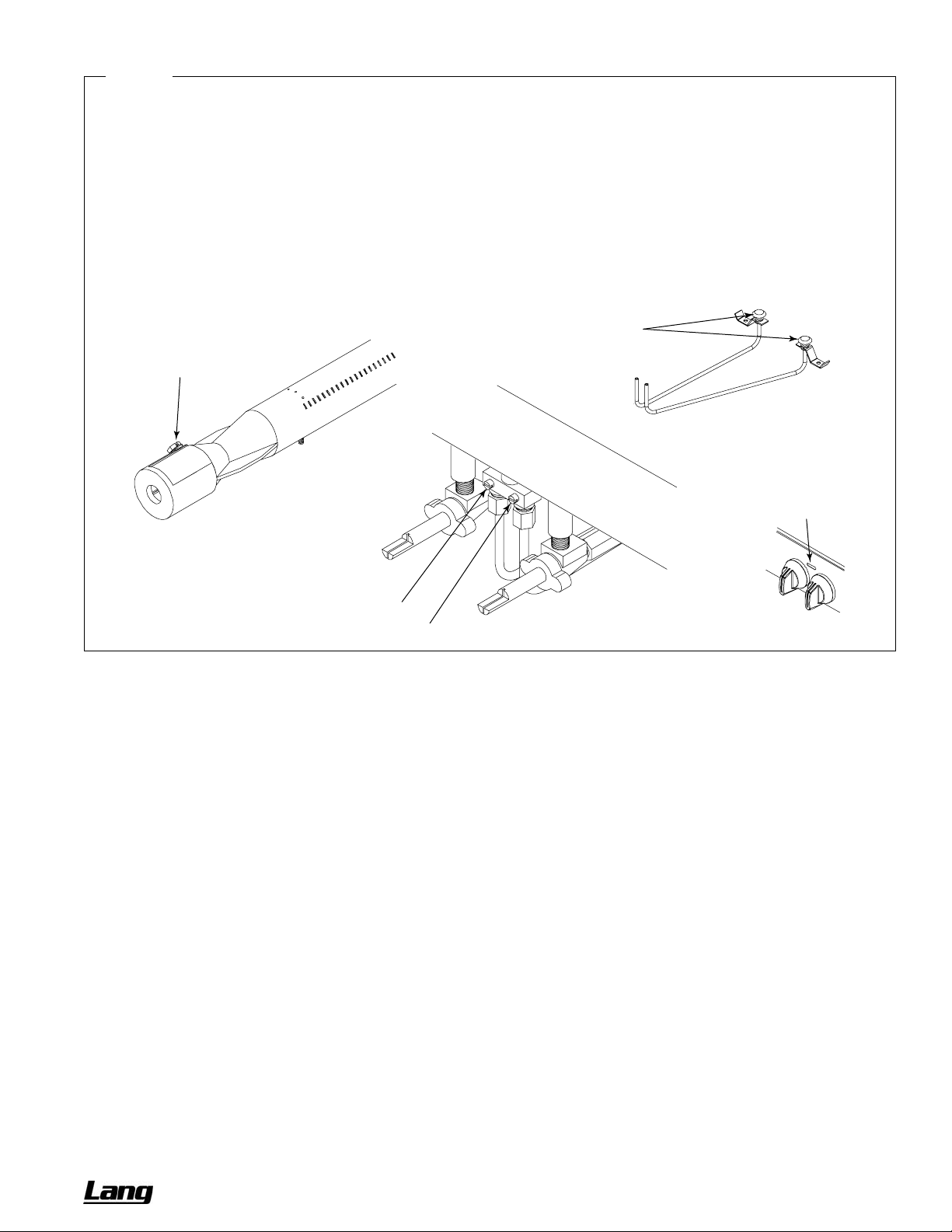
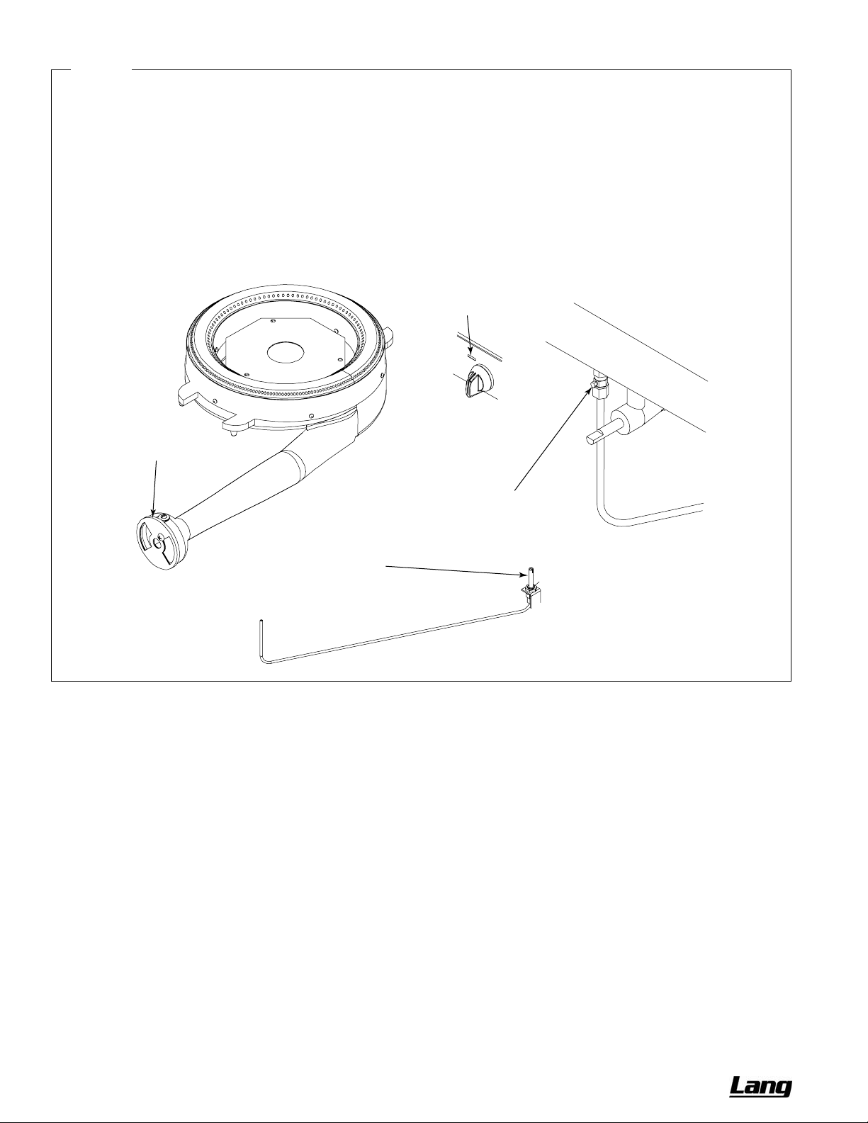
Figure 15
Adjustment of Charbroiler, Standard-Griddle, and Uniform Hot-Top Burners and Pilots
The burner valves are not adjustable. The burner orifice is of the fixed type, sized for the type of gas and the operating altitude.
To adjust the burner air-gas mixture, loosen the screw that secures the air shutter on the mixer face and rotate the mixer cap
to obtain a clear, stable blue flame with a distinct inner cone at each port. Excessive primary air causes “blowing” (the flames
leaving the ports), while insufficient primary air causes a soft or yellow tipped flame.
The pilots are near the front of the burners, and are held in position by brackets. To adjust a pilot flame, insert a screwdriver
through the opening in the valve panel between the control knobs and turn the appropriate pilot adjustment screw
counterclockwise to increase the size of the pilot flame, or clockwise to decrease the size of the pilot flame. The maximum
flame size is approximately 3/4" with a slight yellow tip. The first indication of over-adjustment is when the flame tip becomes
more yellow and begins to generate carbon, which appears as rising black streaks. Continued over-a djustment leads to
unstable lifting and a blowing condition.
Pilots
Air Shutter
Access hole
for pilot
adjustment
Adjustment screw for left-burner pilot
Adjustment screw for right-burner pilot
OWNER’S MANUAL 1192040 REV 1 (01/10) PAGE 31 OF 76
Page 32
SERVICE CHEF SERIES SECTIONAL RANGE
A
Figure 16
Adjustment of Graduated Hot-Top Pilot and Burner
The burner valves are not adjustable. The burner orifice is of the fixed type, sized for the type of gas and the operating altitude.
To adjust the burner air-gas mixture, loosen the screw that secures the air shutter on the mixer face and rotate the mixer cap
to obtain a clear, stable blue flame with a distinct inner cone at each port. Excessive primary air causes “blowing” (the flames
leaving the ports), while insufficient primary air causes a soft or yellow tipped flame.
The pilot is beside the burner, and is held in position by a bracket. To adjust the pilot flame, insert a screwdriver through the
opening in the valve panel beside the control knob and turn the pilot adjustment screw counterclockwise to increase the size of
the pilot flame, or clockwise to decrease the size of the pilot flame. The maximum flame size is approximatel y 3/4" with a slight
yellow tip. The first indication of over-adjustment is when the flame tip becomes more yellow and begins to generate carbon,
which appears as rising black streaks. Continued over-adjustment leads to unstable lifting and a blowing condition.
ccess hole
for pilot
adjustment
Air Shutter
Adjustment screw for pilot
Pilot
PAGE 32 OF 76 OWNER’S MANUAL 1192040 REV 1 (01/10)
Page 33
CHEF SERIES SECTIONAL RANGE SERVICE
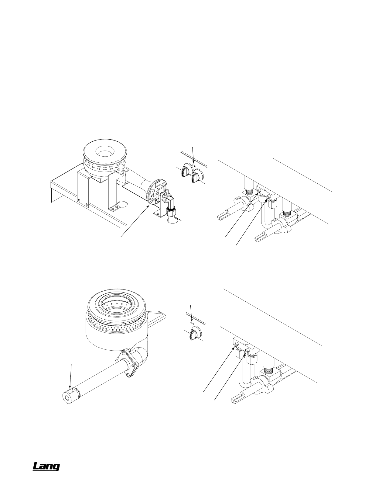
Figure 17
Adjustment of 35K and 45K Open-Top Burners and Pilots
The burner valves are not adjustable. The burner orifice is of the fixed type, sized for the type of gas and the operating altitude.
To adjust the burner air-gas mixture, loosen the screw that secures the air shutter on the mixer face and rotate the mixer cap
to obtain a clear, stable blue flame with a distinct inner cone at each port. Excessive primary air causes “blowing” (the flames
leaving the ports), while insufficient primary air causes a soft or yellow tipped flame.
The pilots are beside the burners, and are held in position by brackets. To adjust a pilot flame, insert a screwdriver through the
opening in the valve panel between the control knobs and turn the appropriate pilot adjustment screw counterclockwise to
increase the size of the pilot flame, or clockwise to decrease the size of the pilot flame. The maximum flame size is
approximately 3/4" with a slight yellow tip. The first indication of over-adjustment is when the flame tip becomes more yellow
and begins to generate carbon, which appears as rising black streaks. Continued over-adjustment leads to unstable lifting and
a blowing condition.
35K-Open-Burner Models
Air Shutter
45K-Open-Burner Model
Access hole
for pilot
adjustment
Adjustment screw for rear-burner pilot
Adjustment screw for front-burner pilot
Access hole
for pilot
adjustment
Air Shutter
Adjustment screw for rear-burner pilot
Adjustment screw for front-burner pilot
OWNER’S MANUAL 1192040 REV 1 (01/10) PAGE 33 OF 76
Page 34
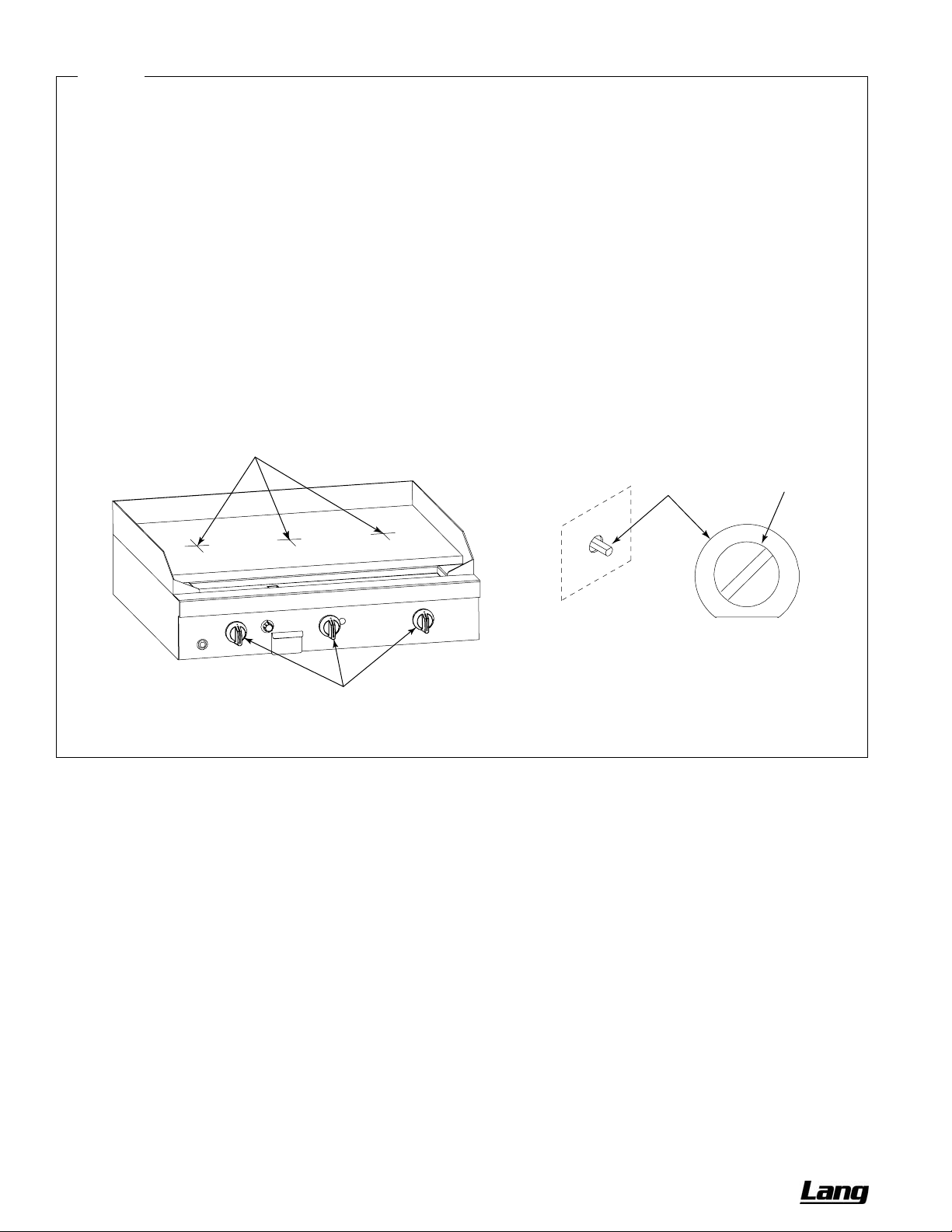
SERVICE CHEF SERIES SECTIONAL RANGE
Figure 18
Adjustment of Thermostatic-Griddle Thermostat
Each 12"-wide section of a thermostatic griddle has a control knob that operates a snap-action thermostatic valve. Each valve
is adjusted at the factory. If the griddle surface temperature is different from the thermostat dial setting, adjust the thermostatic
valve using the following procedure:
1. Turn all the control knobs to the 300°F.
2. Wait 30 minutes for the griddle temperature to stabilize (or 1 hour if the griddle was cold).
3. Place a reliable thermometer or test-instrument thermocouple (able to register 300°F) halfway back from the front to the
back of the griddle and directly in line with the 12"-wide section’s control knob (see drawing below). Check the temperature
of each section every five minutes until the temperature does not change by more than 30°F bet ween two consecutive
measurements.
4. If the average temperature of any section is not within 30°F of the knob setting (300°F), adjust the corresponding
thermostatic valve. To do so, remove the control knob (being careful to not turn the stem, which would change the
temperature setting). While holding the stem in place, turn the calibration screw (see drawing below). If the actual
measured temperature is lower than the dial setting, turn the screw counterclockwise. If the measured temperature is
higher than the dial setting, turn the screw clockwise. Replace the control knob.
5. Wait for the griddle temperature to stabilize, then again check the temperature (as described above).
Measure temperature of each 12"-wide section
half-way back and in line with control knob.
Each knob is attached to a thermostatic
valve located behind the valve panel.
With a control knob removed,
its valve shaft will extend out
of the valve panel.
Shaft
Calibrate the thermostat by holding the
shaft in place while turning the screw
counterclockwise to increase the temperature,
or clockwise to decrease the temperature.
Screw
PAGE 34 OF 76 OWNER’S MANUAL 1192040 REV 1 (01/10)
Page 35
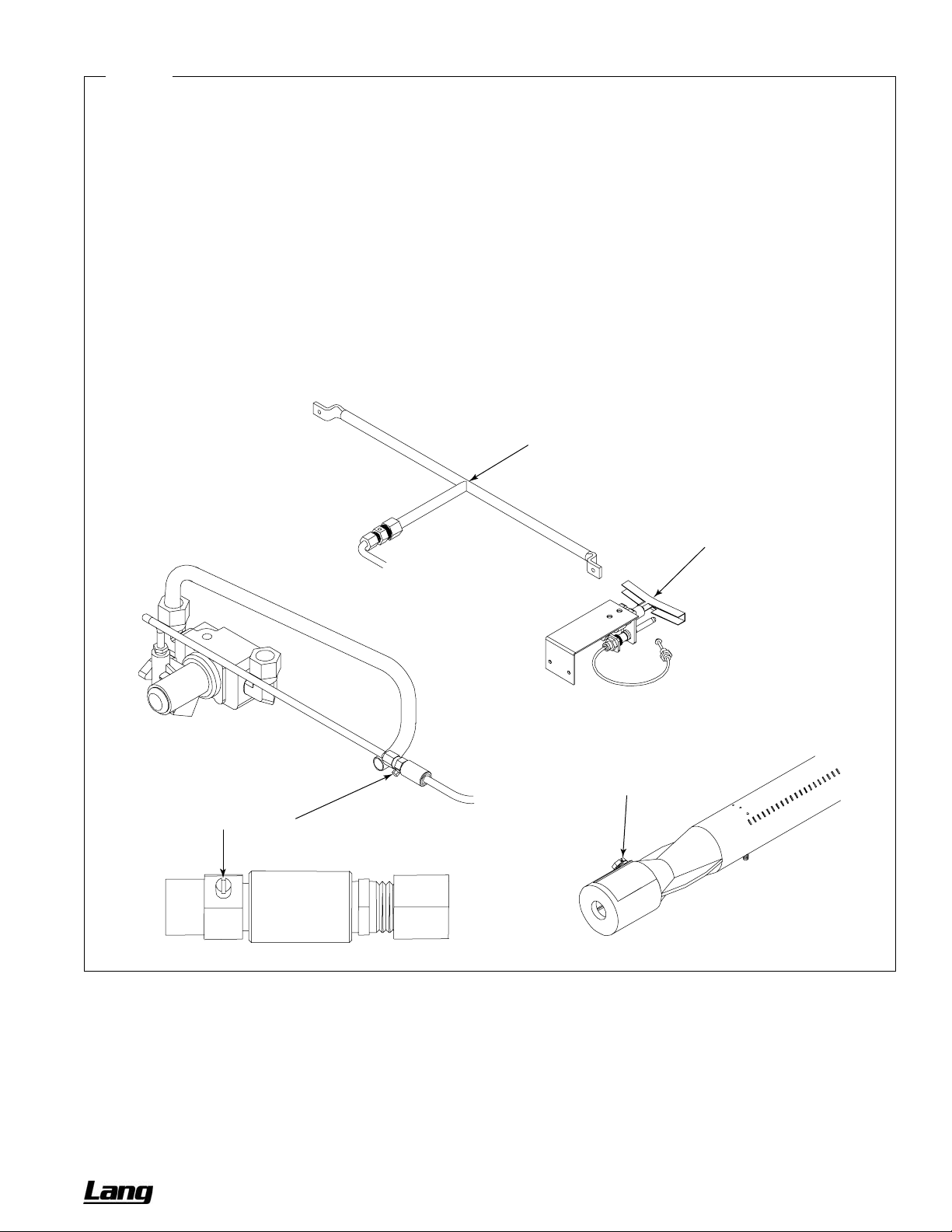
CHEF SERIES SECTIONAL RANGE SERVICE
Figure 19
Adjustment of Thermostatic-Griddle Burners and Pilot
The thermostatic burner valve is adjustable (see page 34). The burner orifice is of the fixed type, sized for the type of gas and
the operating altitude. To adjust the burner air-gas mixture, loosen the screw that secures the air shutter on the mixer face and
rotate the mixer cap to obtain a clear, stable blue flame with a distinct inner cone at each port. Excessive primary air causes
“blowing” (the flames leaving the ports), while insufficient primary air causes a soft or yellow tipped flame.
The pilot(s) and pilot-runner(s) are located near the front of the burners, but the pilot adjustment valve is located in the gas line
between the safety switch and the pilot. If the pilot needs adjustment, do the following:
1. Remove the control knobs, and remove the valve panel (see page
2. If necessary, light the pilot.
3. Locate the pilot adjustment valve (see drawing below). Turn the pilot adjustment screw counterclockwise to increase the
size of the pilot flame, or clockwise to decrease the size of the pilot flame. The pilot flame should be about 1/2" high with a
slight yellow tip, and cover the thermocouple tip. The first indication of over-adjustment is when the flame tip becomes more
yellow and begins to generate carbon, which appears as rising black streaks. Continued over-adjustment leads to unstable
lifting and a blowing condition.
4. Replace the valve panel and control knobs.
29).
Pilot Runner
Pilot
Air Shutter
Adjustment screw for pilot
OWNER’S MANUAL 1192040 REV 1 (01/10) PAGE 35 OF 76
Page 36
SERVICE CHEF SERIES SECTIONAL RANGE
TROUBLESHOOTING OVEN
CAUTION
Proper and efficient operation of oven is dependent on correct installation and function of components. Always
verify that components are in place and functioning as intended.
The following table lists the possible causes of oven-related problems that may occur.
Problem Look for -1
Oven will not come on. – Oven gas shut-off valve is OFF
– Power switch is OFF
– Problem with power switch
– Problem with pilot solenoid
– Problem with main gas solenoid
– Problem with wiring
– Problem with spark ignition module
– Problem with flame sensor switch
Oven pilot will not light – Oven gas shut-off valve is OFF
– Problem with power switch
– Problem with pilot solenoid
– Problem with wiring
– Problem with spark ignition module
Convection blower motor will not run – Problem with fan speed switch
– Problem with door switch
– Problem with blower motor
– Problem with wiring
Oven will not maintain set temperature – Problem with oven thermostat
– Problem with door switch
Oven door too difficult to lift – Problem with door spring
– Problem with door roller assembly
SERVICING CONVECTION OVEN BLOWER MOTOR
WARNING
Before attempting to service or replace any electrical component, make sure that the power source has been
disconnected.
CAUTION
When changing motor or servicing unit, always verify that blower wheel rotation is clockwise when looking into the
oven cavity.
The motor is serviceable from the front of the unit through the oven cavity (see page 29).
Motor lubrication information can be found on the permanent label located on the motor.
If the blower does not run at all, consult the wiring diagrams in this manual (see page
plate.
If the blower runs intermittently, consult the following flowchart.
41), or behind the oven kick
PAGE 36 OF 76 OWNER’S MANUAL 1192040 REV 1 (01/10)
Page 37
CHEF SERIES SECTIONAL RANGE SERVICE
p
BLOWER RUNS
INTERMITTENTLY
Blower
Cold
starts but
Hot
shuts off.
REMOVE THE MAIN POWER
SOURCE. UNPLUG OR
DISCONNECT CIRCUIT
BREAKER.
Check all wiring for loose
connections or breaks.
Go to the junction box on the back
of the range and remove the cover.
Place a DVM or ammeter on the
black wire #1.
CAUTION! Be sure a DVM is
protected to 40 amps or greater.
Connect main power supply.
Turn on the oven Power Switch.
Check that there are no air flow
obstructions around the range.
Check that the motor is not against
a wall.
Check that the vents at each end of
the motor are not obstructed.
Check for excessive grease and
dust buildup on the motor.
Check for excessive heat sources
behind the range.
Check for hot air leaks around the
motor pocket.
Leave the blower turned on and
turn off the oven thermostat and
allow to cool.
Observe that the amperage surges
and returns to the motor amperage
reading for high speed.
If the blower starts up turn the oven
on and allow to reheat to 500°F.
If the amperage surge remains at a
value greater than the rating
replace the motor.
If the motor shuts off and there
is no excessive heat around the
blower motor it must be
laced.
re
Test oven.
OWNER’S MANUAL 1192040 REV 1 (01/10) PAGE 37 OF 76
Page 38
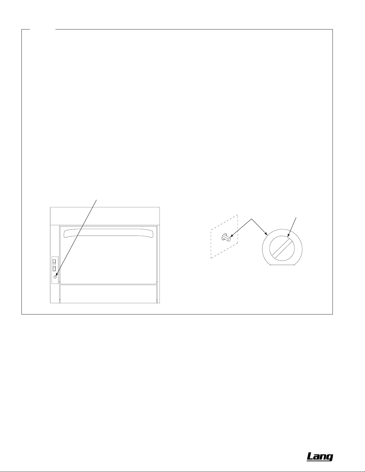
SERVICE CHEF SERIES SECTIONAL RANGE
t
Figure 20
Adjustment of Oven Thermostat
The oven thermostat is carefully calibrated at the factory so that the dial setting matches the actual oven temperature. Field
recalibration is seldom necessary, and should not be resorted to unless considerable cooking e x perience definitely proves that
the control is not maintaining the temperatures to which the dial is set.
Obtain a test instrument or a reliable mercury thermometer, then do the following:
1. Place the thermocouple of test instrument or the thermometer in the middle of the oven.
2. Turn on the oven and set the thermostat to 400°F.
3. After the oven has been on about 20 minutes check oven temperature. The oven door should be open for as short a time
as possible. Use a flashlight, if necessary, to see the thermometer clearly.
4. Continue to check the temperature at 5-minute intervals until two successive readings are within 5 degrees of each other.
The thermostat should be recalibrated if the reading is not within 20 degrees of the dial setting (400°F ). If calibration is
required, adjust the thermostat, as follows:
5. Remove the oven temperature control knob. Be careful to not turn the stem (which would change the temperature setting).
6. While holding the stem in place, turn the calibration screw (see drawing below). If the actual measured temperature is lower
than the dial setting, turn the screw counterclockwise. If the measured temperature is higher than the dial setting, turn the
screw clockwise. Replace the control knob.
7. Set the oven temperature to 450°F. After about 20 minutes, check the oven temperature. Continue to check the
temperature at 5-minute intervals until two successive readings are within 5 degrees of each other. If the actual oven
temperature is not within 20 degrees of the dial setting (450°F), replace the thermostat.
Remove oven thermosta
control knob.
With the control knob removed,
the control shaft will extend out
of the control panel.
Shaft
Screw
Calibrate the thermostat by holding the
shaft in place while turning the screw
counterclockwise to increase the temperature,
or clockwise to decrease the temperature.
PAGE 38 OF 76 OWNER’S MANUAL 1192040 REV 1 (01/10)
Page 39
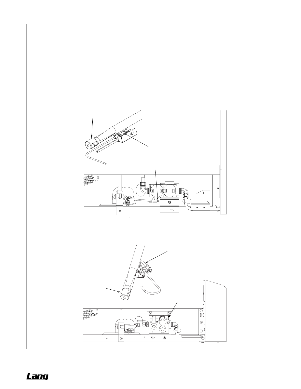
CHEF SERIES SECTIONAL RANGE SERVICE
Figure 21
Adjustment of Oven Pilot and Burner
The burner orifice is of the fixed type, sized for the type of gas and the operating altitude. To adjust the burner air-gas m ixture,
loosen the screw that secures the air shutter on the mixer face and rotate the mixer cap to obtain a clear, stable blue flame
with a distinct inner cone at each port. Excessive primary air causes “blowing” (the flames leaving the ports), while insufficient
primary air causes a soft or yellow tipped flame.
The oven pilot flame is adjusted by using a screwdriver to turn the adjusting screw on the pilot line valv e (see drawing below).
The pilot line valve is located behind the kick panel below the oven door. To gai n access, lift the kick panel straight up and pull
the top edge out. The pilot flame is properly adjusted when it is just large enough to maintain a glowing red color of the
thermopile capillary bulb. The first indication of over-adjustment is when the flame tip becomes yellow and begins to generate
carbon, which appears as rising black streaks. Continued over-adjustment leads to unstable lifti ng and a blowing condition.
UNITS WITH ELECTRONIC IGNITION
Air Shutter
Pilot
Air Shutter
Adjustment Screw for Pilot
UNITS WITH STANDING PILOT
Pilot
Adjustment Screw for Pilot
OWNER’S MANUAL 1192040 REV 1 (01/10) PAGE 39 OF 76
Page 40

SERVICE CHEF SERIES SECTIONAL RANGE
ADJUSTMENT OF MANIFOLD GAS PRESSURE
There is not an internal pressure regulator. The external pressure regulators supplied by Lang are factory set at 6"
W.C. for natural gas and 10" W.C. for propane gas. To check the manifold pressure, do the following:
1. Turn OFF all thermostats, burner controls, gas shut-off valves, and the external gas supply connection(s).
2. Remove the valve panel and locate the 1/8" plug in the front manifold furthest from the gas connection location.
Remove the plug and install a fitting appropriate to connect a manometer.
3. Turn ON all gas supply valves and light all pilots.
4. Turn all burners and ovens to full ON position and read manometer.
5. If manometer does not read 6" W.C. for natural gas (or 10" W.C. for propane gas) adjust regulator by removing
the cap from the top of regulator. Use a screwdriver to rotate the regulator adjustment screw clockwise to
increase pressure, or counterclockwise to decrease pressure, until manometer shows correct reading.
6. Turn OFF all thermostats, burner controls, gas shut-off valves, and the external gas supply connection(s).
7. Remove manometer fitting and replace plug in manifold.
8. Turn ON all gas valves and light all pilots.
9. Replace valve panel.
PAGE 40 OF 76 OWNER’S MANUAL 1192040 REV 1 (01/10)
Page 41
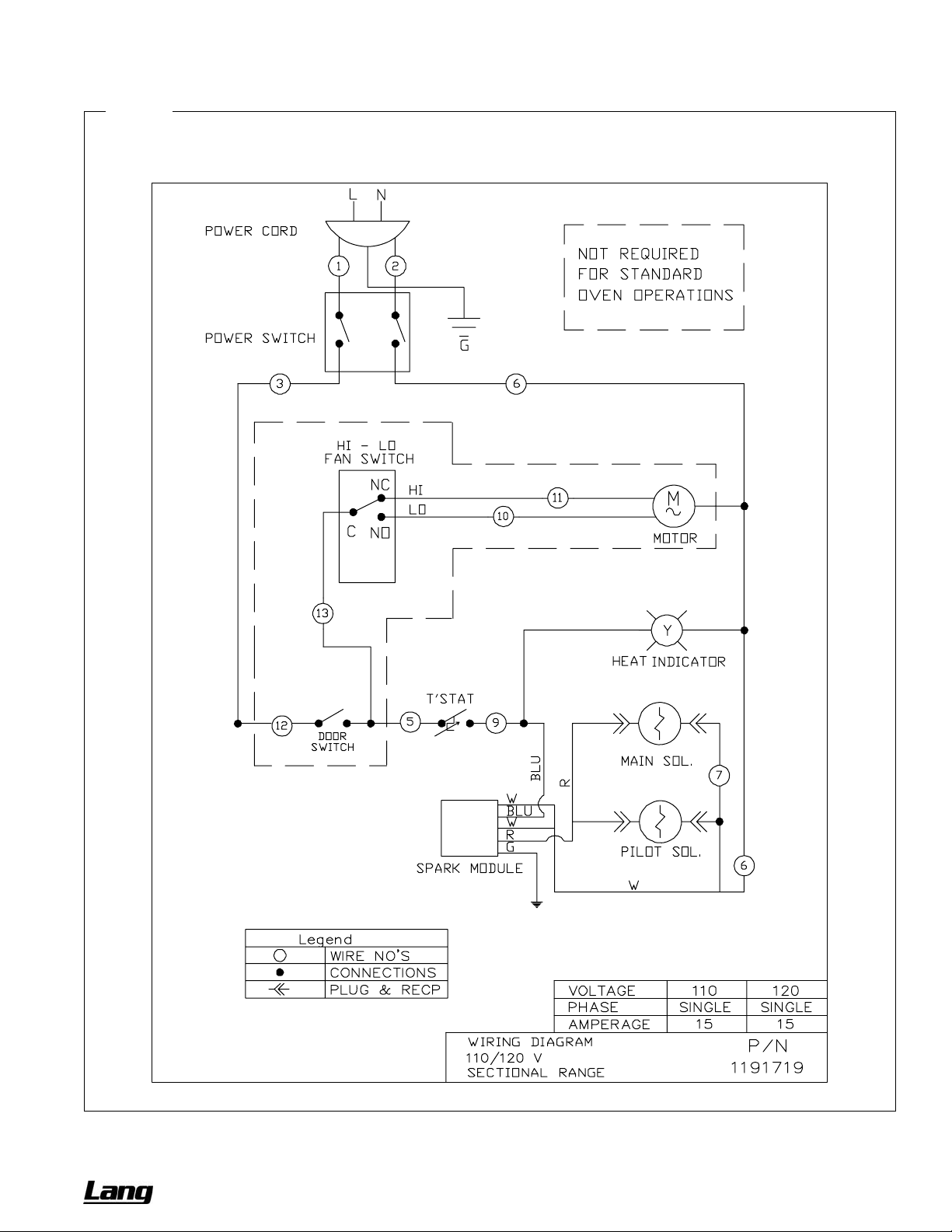
CHEF SERIES SECTIONAL RANGE SERVICE
WIRING DIAGRAMS
Figure 22
Wiring Diagram for 120 Volt Oven Bases with Electronic Ignition
OWNER’S MANUAL 1192040 REV 1 (01/10) PAGE 41 OF 76
Page 42
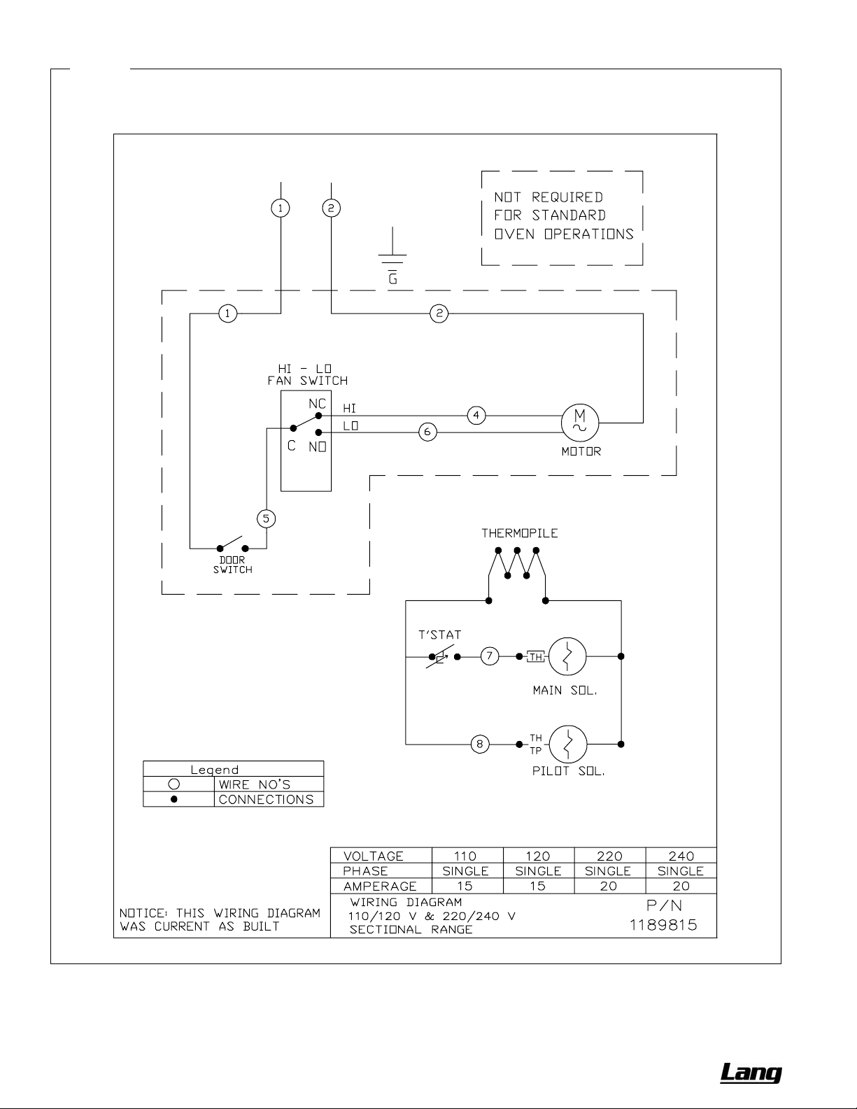
SERVICE CHEF SERIES SECTIONAL RANGE
Figure 23
Wiring Diagram for Oven Bases with Standing Pilot
PAGE 42 OF 76 OWNER’S MANUAL 1192040 REV 1 (01/10)
Page 43

CHEF SERIES SECTIONAL RANGE SERVICE
PARTS
The following tables and figures list serviceable parts. For parts not listed, contact a Lang Authorized Parts Distributor
or a Lang Authorized Service Agency.
Index of Parts Diagrams
Page Number Description
44 Front-Rail Parts
45 Leg and Caster Parts
4 6 35K-Open-Burner External and Structural Parts
48 35K-Open-Burner Gas Train Parts
50 45K-Open-Burner Parts
52 Charbroiler External and Structural Parts
54 Charbroiler and Standard-Griddle Gas Train Parts
55 Gas Connection Parts
56 Griddle External and Structural Parts
58 Thermostatic Griddle Gas Train Parts
60 Uniform Hot-Top Parts
62 Graduated-Hot-Top Parts
64 Oven Base Parts
66 Convection Oven Blower Parts
67 Modular-Countertop Base Parts
68 Cabinet-Base Parts
70 Flue Riser Parts
72 Side Panel and Battery-Assembly Parts
OWNER’S MANUAL 1192040 REV 1 (01/10) PAGE 43 OF 76
Page 44
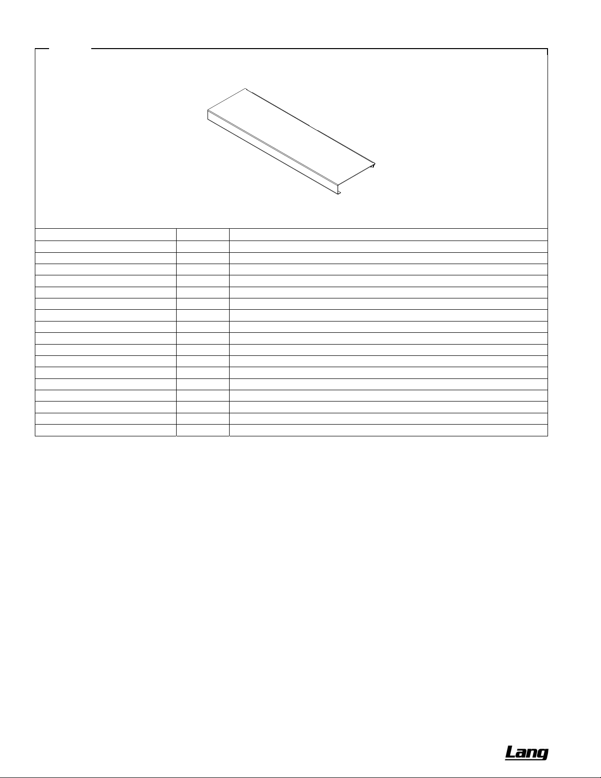
SERVICE CHEF SERIES SECTIONAL RANGE
Figure 24
Front-Rail Parts
For custom front rails, or continuous rails spanning multiple sections, contact Lang.
Models Part Number Description
LGR12_-B, -H 1192051 FRONT RAIL, 9"
LGR12_-G, -C 1192053 FRONT RAIL, 9"
LGR18_-X 1192055 FRONT RAIL, 9"
LGR24_-BB 1192057 FRONT RAIL, 9"
LGR24_-HH 1192059 FRONT RAIL, 9"
LGR24_-GG, -CC 1192061 FRONT RAIL, 9"
LGR36_-BBB, -GRAD, -XXX 1192063 FRONT RAIL, 9"
LGR36_-HHH, -BHH, -BBH 1192065 FRONT RAIL, 9"
LGR36_-GGG, -CCC, -TTT 1192067 FRONT RAIL, 9"
LGR36_-BGG, -BCC, -BTT 1192085 FRONT RAIL, 9"
LGR36_-GGB, -CCB, -TTB 1192087 FRONT RAIL, 9"
LGR36_-BBG, -BBC 1192089 FRONT RAIL, 9"
LGR36_-GBB, -CBB 1192091 FRONT RAIL, 9"
LGR36_-CTT, -CGG, -GCC 1192101 FRONT RAIL, 9"
LGR36_-TTC, -GGC, -CCG 1192103 FRONT RAIL, 9"
LGR48_-BBBB 1192069 FRONT RAIL, 9"
LGR48_-CCCC, -GGG, -TTT 1192071 FRONT RAIL, 9"
PAGE 44 OF 76 OWNER’S MANUAL 1192040 REV 1 (01/10)
Page 45
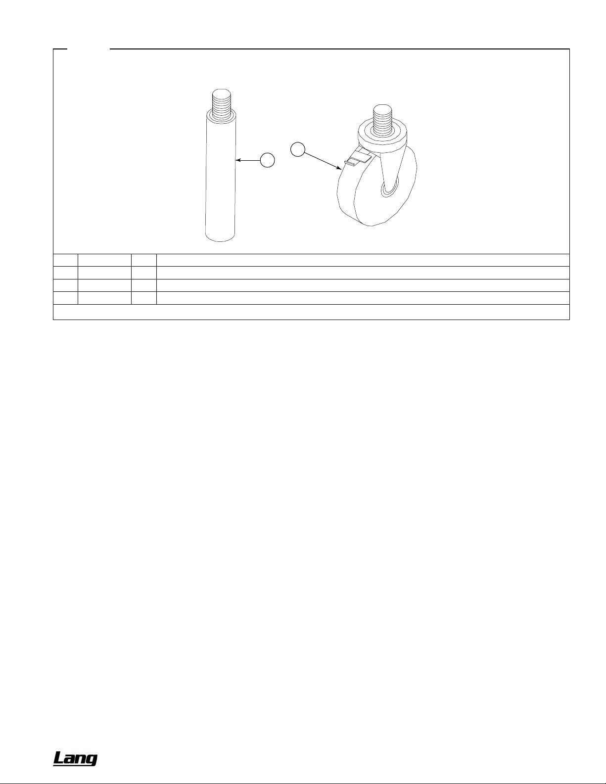
CHEF SERIES SECTIONAL RANGE SERVICE
Figure 25
Leg and Caster Parts
2
1
Key Part Number Qty Description
1 1174260 1
* 1174262 1
2 1174265 1
* Not shown in drawing.
LEG PACKAGE (set of four legs, not including bolts, leg pads, or lock washers)
EARTHQUAKE LEGS SS (set of four)
CASTER PACKAGE (two casters with brake and two without brake; does not include bolts, lock washers, or leg pads)
OWNER’S MANUAL 1192040 REV 1 (01/10) PAGE 45 OF 76
Page 46

SERVICE CHEF SERIES SECTIONAL RANGE
35K-Open-Burner External and Structural Parts
See drawing on following page.
Key Part Number
1 1183978 1 - -
1183974 - 1 -
1183972 - - 1
2 1192000 2 4 6
3 1184729 1 - -
1184730 1 - -
1184727 - 1 -
1184728 - 1 -
1183614 - - 1
1184610 - - 1
1184609 - - 1
4 1183897 2 - -
1183896 - ** -
1183597 - - **
5 1183883 1 - -
1183882 - 1 -
1183601 - - 1
6 1180872 1 2 3
7 1183888 1 - -
1183886 - 1 -
1183531 - - 1
8 1183900 1 - -
1183898 - 1 -
1183589 - - 1
9 1183500 1 2 3
10 1183501 - 4 6
11 1184672 - 1 -
1184671 - - 1
12 1184649 - 1 -
1184648 - - 1
13 1177109 - 2 3
14 1177107 - 2 3
15 1177108 - 2 3
16 1184790 - 2 3
Quantity*
12" 24" 36"
Description
TRAY ASSEMBLY, 12" CRUMB
TRAY ASSEMBLY, 24" CRUMB
TRAY ASSEMBLY, 36" CRUMB
KNOB
VALVE PANEL, 12C-B (cabinet base)
VALVE PANEL, 12N-B (modular-countertop base)
VALVE PANEL, 24C-BB (cabinet base)
VALVE PANEL, 24N-BB (modular-countertop base)
VALVE PANEL, 36A/D-BBB (oven base)
VALVE PANEL, 36C-BBB (cabinet base)
VALVE PANEL, 36N-BBB (modular-countertop base)
BURNER REST, 12
BURNER REST, 24
BURNER REST, 36
SUPPORT, 12 PILOT (for flush-top models)
SUPPORT, 24 PILOT (for flush-top models)
SUPPORT, 36 PILOT (for flush-top models)
BRACKET, PILOT SUPPORT (for flush-top models)
TRIM, 12 FLUE RISER
TRIM, 24 FLUE RISER
TRIM, 36 FLUE RISER
TRIM, 42 DEEP 12 FLUE RISER
TRIM, 42 DEEP 24 FLUE RISER
TRIM, 42 DEEP 36 FLUE RISER
CAST IRON GRATE, SECTIONAL
CAST IRON GRATE, SECTIONAL HALF (for step-up models)
SUPPORT W/A, STEP-UP 24" GRATE
SUPPORT W/A, STEP-UP 36" GRATE
BURNER REST, 24" STEP-UP
BURNER REST, 36" STEP-UP
BRACKET, REAR BURNER REST (for step-up models)
BRACKET, ORIFICE (for rear burners of step-up models)
BRACKET, REAR PILOT (for rear pilots of step-up models)
BRACKET, STEP-UP PILOT (for front pilots of step-up models)
* Quantity of part used may depend on width of section (12", 24", or 36").
** Two for flush-top models, one for step-up models.
PAGE 46 OF 76 OWNER’S MANUAL 1192040 REV 1 (01/10)
Page 47
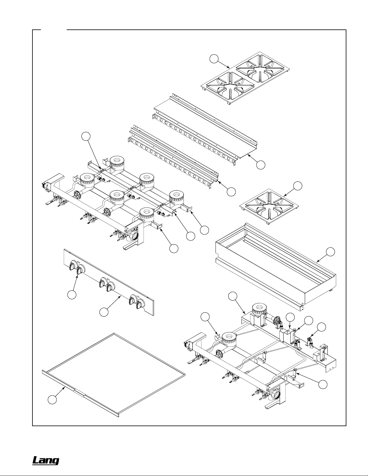
CHEF SERIES SECTIONAL RANGE SERVICE
Figure 26
35K-Open-Burner External and Structural Parts
See parts list on previous page.
9
Flush 35K-Open-Burner Models
6
8
10
7
4
5
4
2
3
4
12
13
15
11
14
16
1
Step-Up 35K-Open-
Burner Models
36"-Wide Models Shown
OWNER’S MANUAL 1192040 REV 1 (01/10) PAGE 47 OF 76
Page 48
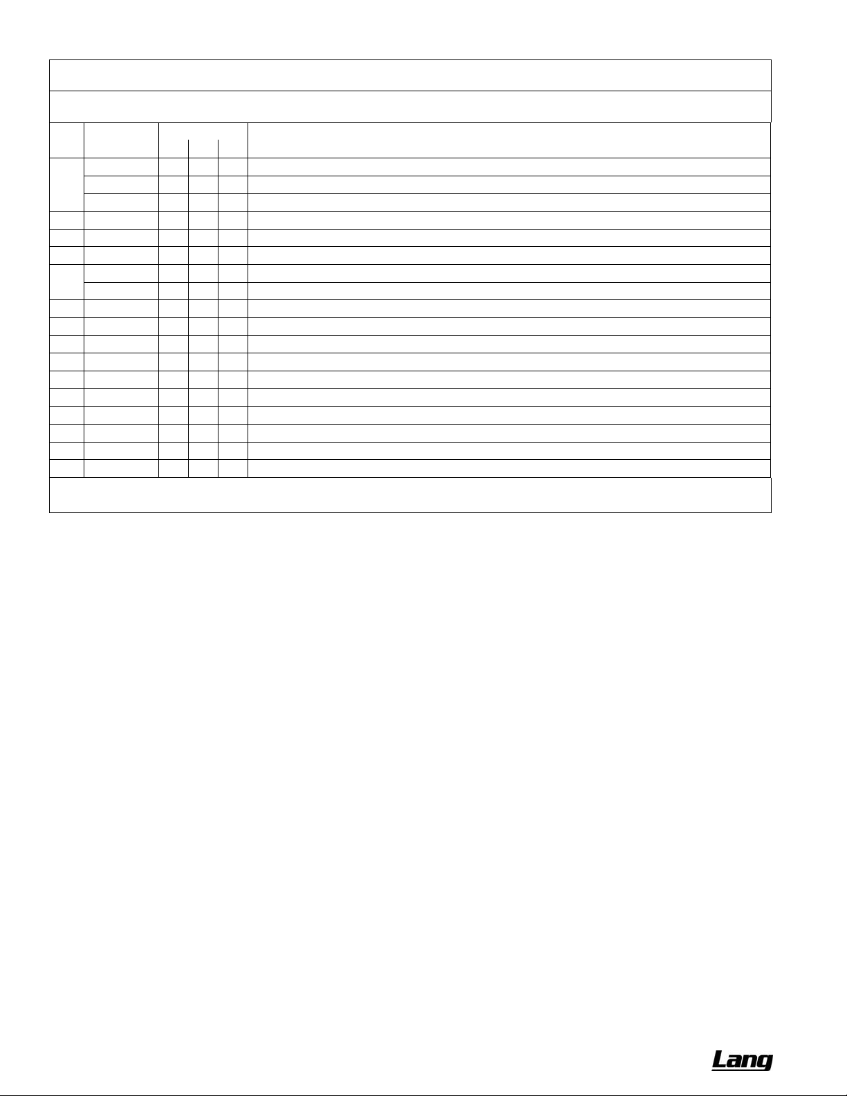
SERVICE CHEF SERIES SECTIONAL RANGE
35K-Open-Burner Gas Train Parts
See drawing on following page.
Key Part Number
1 1183923 1 - -
1183922 - 1 -
1183593 - - 1
2 1179222 2 4 6
3 1178202 2 4 6
4 1179188 1 2 3
** 1008737 2 4 6
1008752 2 4 6
5 1182193 2 4 6
** 1182195 1 2 3
6 1182192 1 2 3
7 1182191 1 2 3
8 1166004 1 2 3
9 1183605 1 2 3
10 1183603 1 2 3
11 1177106 - 2 3
12 1184646 - 1 2
13 1184647 - 1 1
Quantity*
12" 24" 36"
Description
MANIFOLD W/A, 2 BURNER OPEN TOP
MANIFOLD W/A, 4 BURNER OPEN TOP
MANIFOLD W/A, 6 BURNER OPEN TOP
NIPPLE, EXTENSION
VALVE, HI-OFF, NAT/LP
EXTENSION, ORIFICE
ORIFICE, NAT GAS (if appliance will operate above 2000 ft, contact Lang for appropriate orifice size)
ORIFICE, PROPANE (if appliance will operate above 2000 ft, contact Lang for appropriate orifice size)
BURNER ASSEMBLY, OPEN TOP
FITTING, 1/2" COMP 1/4" NPT (connects rear-burner gas tube to valve)
TUBE, REAR BURNER
ORIFICE FITTING
FITTING, DOUBLE PILOT, 3/16" TUBE
PILOT TUBE W/A REAR
PILOT TUBE W/A FRONT
TUBE ASM, REAR BURNER PILOT (for rear pilots of step-up models)
TUBE, REAR BURNER STEP-UP (for left rear burner of step-up models, and center rear burner of 36"-wide step-up model)
TUBE, REAR BURNER STEP-UP (for right rear burner of step-up models)
* Quantity of part used may depend on width of section (12", 24", or 36").
** Not shown on drawing.
PAGE 48 OF 76 OWNER’S MANUAL 1192040 REV 1 (01/10)
Page 49
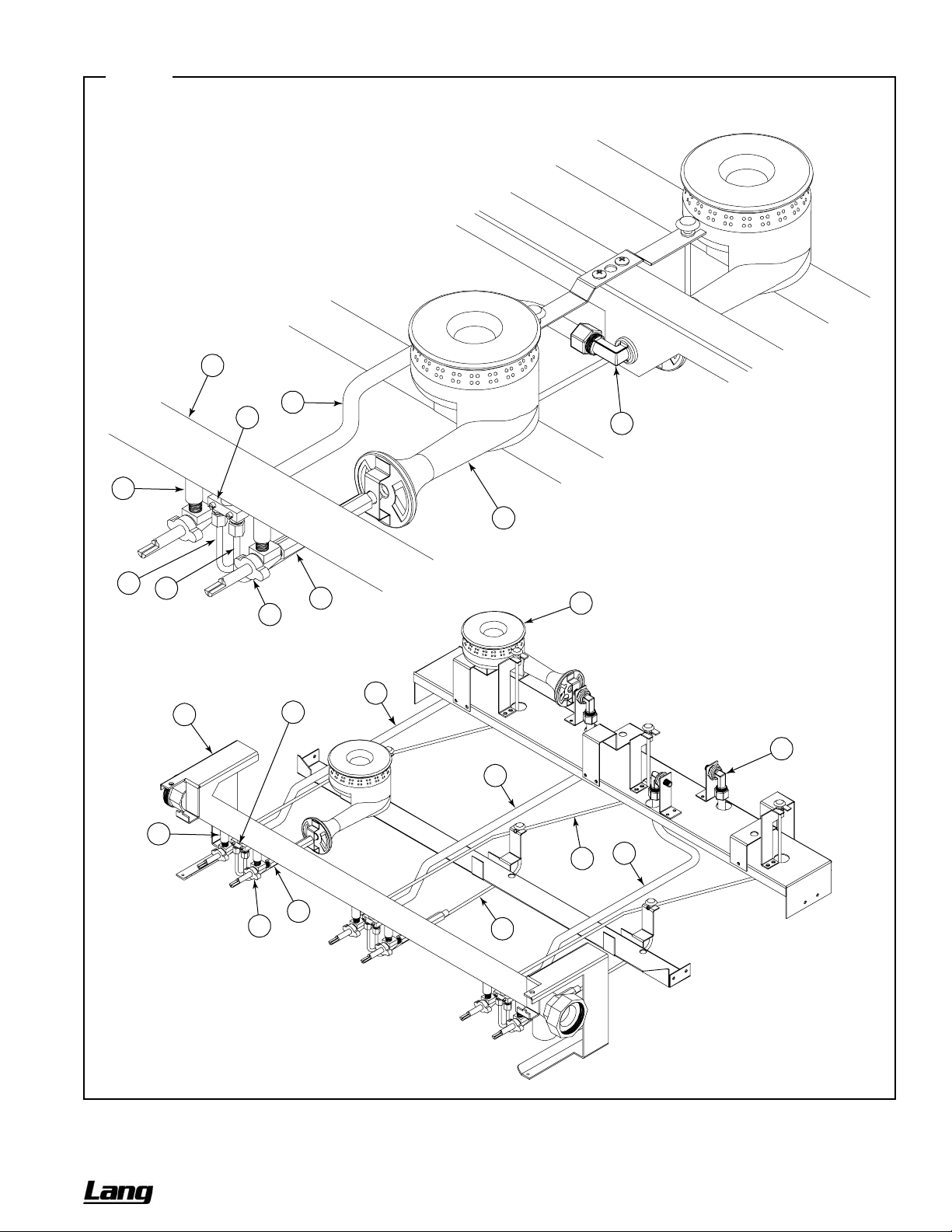
CHEF SERIES SECTIONAL RANGE SERVICE
Figure 27
35K-Open-Burner Gas Train Parts
See parts list on previous page.
Flush 35K-Open-Burner Models
1
6
8
7
2
5
9
10
3
4
5
Step-Up 35K-Open-Burner Models
12
1
8
7
12
2
13
11
4
3
10
36"-Wide Models Shown
OWNER’S MANUAL 1192040 REV 1 (01/10) PAGE 49 OF 76
Page 50
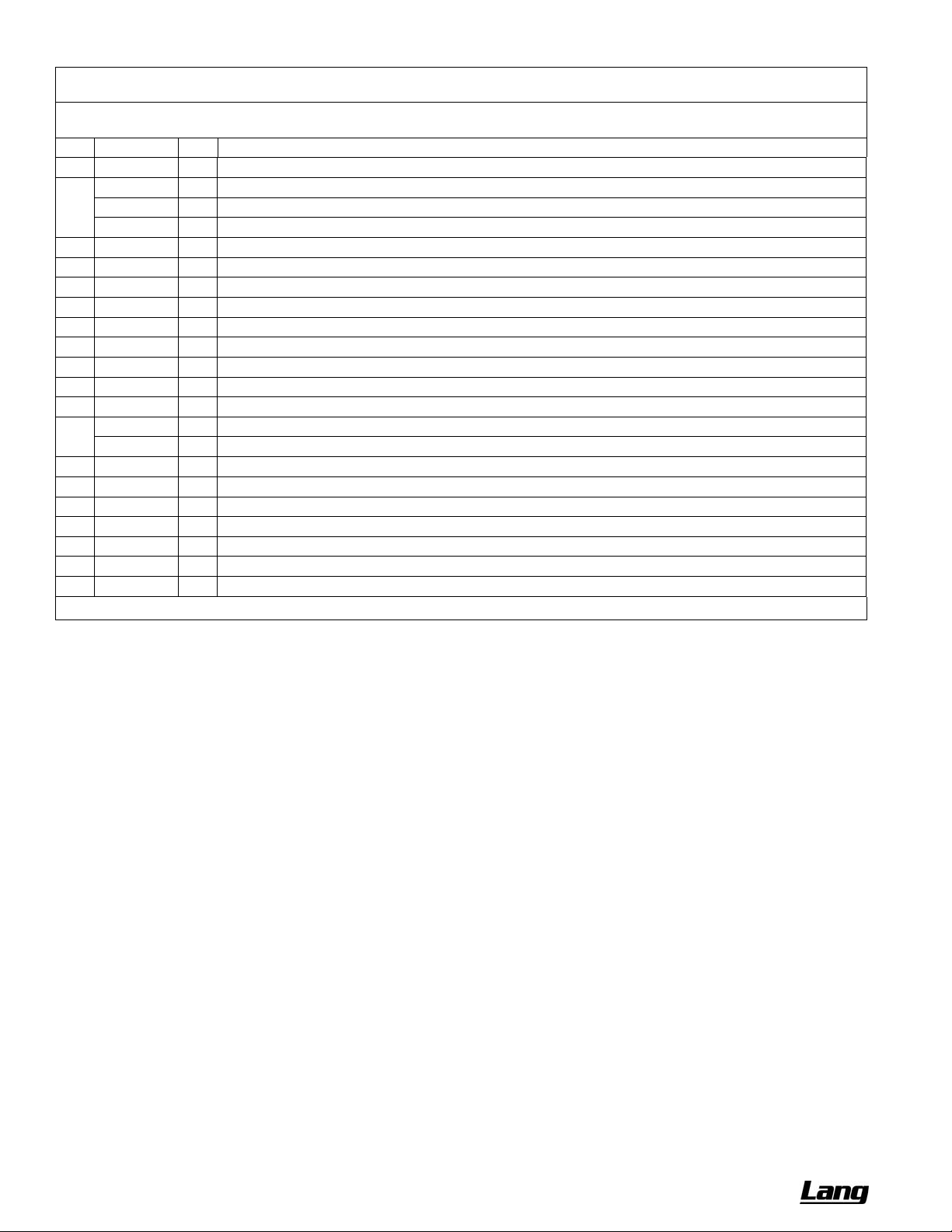
SERVICE CHEF SERIES SECTIONAL RANGE
45K-Open-Burner Parts
See drawing on following page.
Key Part Number Qty Description
1 1192000 4
2 1184415 1
1184407 1
1184406 1
3 1183972 1
4 1185008 2
5 1179229 2
6 1183531 1
7 1183589 1
8 1184499 2
9 1184883 1
10 1179222 4
11 1178202 4
* 1008735 4
* 1008750 4
12 1179240 2
13 1179241 2
14 1179230 4
15 1177043 4
16 1166004 2
17 1179246 2
18 1179244 2
* Not shown on drawing.
KNOB
VALVE PANEL, 36A/D-XX (oven base)
VALVE PANEL, 36C -XX (cabinet base)
VALVE PANEL, 36N-XX (modular-countertop base)
TRAY ASSEMBLY, 36" CRUMB
BURNER SUPPORT
SUPPORT, PILOT
TRIM 36 DEEP 36 FLUE RISER
TRIM 42 DEEP 36 FLUE RISER
CAST IRON GRATE
MANIFOLD W/A
NIPPLE, EXTENSION
VALVE, HI-OFF, NAT/LP
ORIFICE, NAT GAS (if appliance will operate above 2000 ft, contact ??????????? for appropriate orifice size)
ORIFICE, PROPANE (if appliance will operate above 2000 ft, contact ????????? for appropriate orifice size)
BURNER, VENTURI (for front burners)
BURNER, VENTURI (for rear burners)
BURNER HEAD, 40
COVER, BURNER DRIP
FITTING, DOUBLE PILOT, 3/16" TUBE
PILOT W/A, REAR
PILOT W/A, FRONT
PAGE 50 OF 76 OWNER’S MANUAL 1192040 REV 1 (01/10)
Page 51
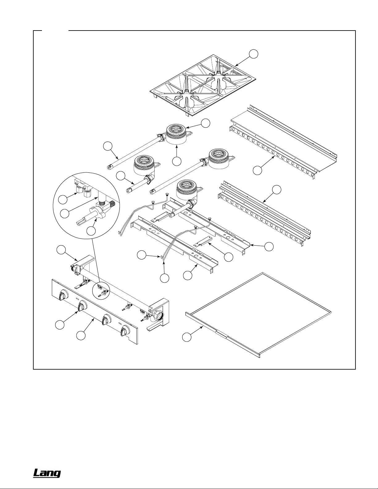
CHEF SERIES SECTIONAL RANGE SERVICE
Figure 28
45K-Open-Burner Parts
See parts list on previous page.
13
16
10
11
8
15
14
7
12
6
9
17
18
4
5
4
1
2
3
OWNER’S MANUAL 1192040 REV 1 (01/10) PAGE 51 OF 76
Page 52

SERVICE CHEF SERIES SECTIONAL RANGE
Charbroiler External and Structural Parts
See drawing on following page.
Key Part Number
1 1192000 2 3 4
2 1184519 1 - -
1184521 1 - 1183641 - 1 1183643 - 1 1183642 - 1 1185396 - - 1
1185397 - - 1
1185398 - - 1
3 1184773 2 3 4
4 1184523 1 - -
1184522 - 1 -
1185379 - - 1
5 1183896 1 - -
1183524 - 1 -
1183895 - - 1
6 1183901 1 - -
1184543 - 1 -
1185388 - - 1
7 1183974 2 - -
1184772 - 2 -
1185401 - - 1
1185486 - - 1
8 1184994 2 3 4
9 1183890 1 - -
1183635 - 1 -
1183889 - - 1
10 1183893 1 - -
1183590 - 1 -
1183892 - - 1
11 1183541 1 1 1
12 1183542 1 1 1
13 1183610 1 - -
1183609 - 1 -
1183649 - - 1
14 1183926 1 - -
1183525 - 1 -
1183928 - - 1
15 1183786 1 - -
1183646 - 1 -
1183789 - - 1
16 1183676 2 3 4
17 1182657 4 6 8
** 1173193 4 6 8
18 1178976 4 6 8
** 1182838 4 6 8
* Quantity of part used may depend on width of section (24", 36" or 48")
** Not shown on drawing.
Quantity*
24" 36" 48"
Description
KNOB
VALVE PANEL, 24C-CC, SS
VALVE PANEL, 24N-CC, SS
VALVE PANEL, 36A/D-CCC, SS
VALVE PANEL, 36C-CCC, SS
VALVE PANEL, 36N-CCC, SS
VALVE PANEL, 48A/D-CCCC, SS
VALVE PANEL, 48C-CCCC, SS
VALVE PANEL, 48N-CCCC, SS
COVER, VALVE SHIELD
SHIELD, 24" VALVE HEAT
SHIELD, 36" VALVE HEAT
SHIELD, 48" VALVE HEAT
BURNER REST, 24 CHAR/GRI
BURNER REST, 36 CHAR/GRI
BURNER REST, 48 CHAR/GRI
SHIELD, 24" CHARBROILER HEAT
SHIELD, 36" CHARBROILER HEAT
SHIELD, 48" CHARBROILER HEAT
TRAY W/A, 24 CHARBROILER CRUMB
TRAY W/A, 36 CHARBROILER CRUMB
TRAY W/A, 48 CHARBROILER CRUMB LT
TRAY W/A, 48 CHARBROILER CRUMB RT
BRACKET, RADIANT STOP
TRIM, CHAR/GRI 24 FLUE RISER
TRIM, CHAR/GRI 36 FLUE RISER
TRIM, CHAR/GRI 48 FLUE RISER
TRIM, 42 DEEP CHAR/GRI 24 FLUE RISER
TRIM, 42 DEEP CHAR/GRI 36 FLUE RISER
TRIM, 42 DEEP CHAR/GRI 48 FLUE RISER
SHIELD, LEFT DRIP
SHIELD, RIGHT DRIP
SUPPORT, 24" CHRBRLR GRATE
SUPPORT, 36" CHRBRLR GRATE
SUPPORT, 48" CHRBRLR GRATE
SHIELD, 24" REAR DRIP
SHIELD, 36" REAR DRIP
SHIELD, 48" REAR DRIP
CHARBROILER W/A, 24
CHARBROILER W/A, 36
CHARBROILER W/A, 48
RADIANT W/A
GRATE, LAVA ROCK
LAVA ROCK BRIQUETTES, BAG
CHARBROILER GRID
PLATED FISH GRID
PAGE 52 OF 76 OWNER’S MANUAL 1192040 REV 1 (01/10)
Page 53

CHEF SERIES SECTIONAL RANGE SERVICE
Figure 29
Charbroiler External and Structural Parts
See parts list on previous page.
18
17
16
14
15
11
13
12
8
7
6
5
10
9
1
2
OWNER’S MANUAL 1192040 REV 1 (01/10) PAGE 53 OF 76
Page 54
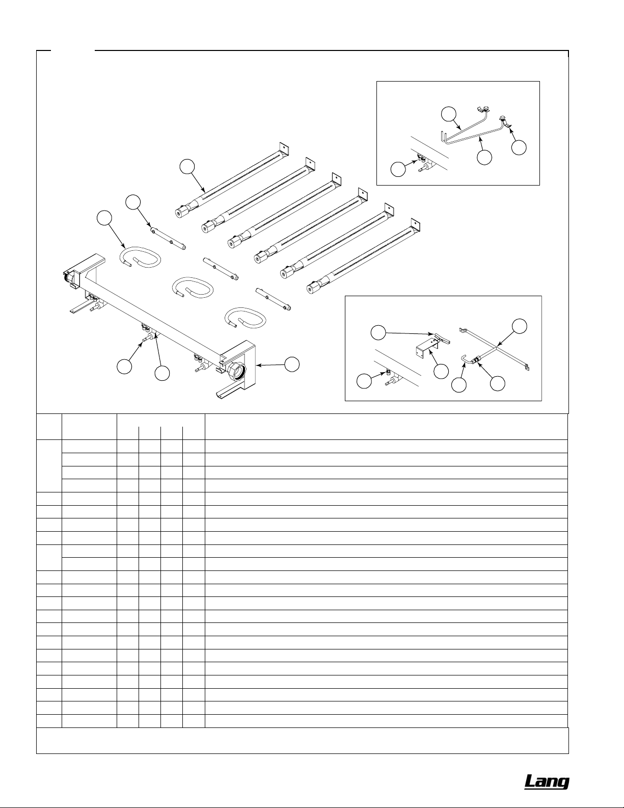
SERVICE CHEF SERIES SECTIONAL RANGE
Figure 30
Charbroiler and Standard-Griddle Gas Train Parts
Pilot Parts for Charbroiler Models
8
6
5
4
3
2
1
36"-Wide Model Shown
Key Part Number
1 1183920 1 - - -
1183919 - 1 - -
1183675 - - 1 -
1183921 - - - 1
2 1179222 1 2 3 4
3 1176008 1 2 3 4
4 1183503 1 2 3 4
5 1183680 1 2 3 4
** 1008748 2 4 6 8
1008756 2 4 6 8
6 1182762 2 4 6 8
7 1166004 1 2 3 4
8 1184505 1 2 3 4
9 1184506 1 2 3 4
10 1182821 2 4 6 8
11 1099002 1 1 1 1
** 1184541 1 1 1 2
12 1183687 1 1 1 2
13 1183681 1 1 1 2
14 1183573 - 1 2 2
15 1183584 - 1 2 2
16 1183536 - 1 2 2
Quantity*
12" 24" 36" 48"
Description
MANIFOLD W/A, 12, CHAR/GRI SECT
MANIFOLD W/A, 24, CHAR/GRI SECT
MANIFOLD W/A, 36, CHAR/GRI SECT
MANIFOLD W/A, 48, CHAR/GRI SECT
NIPPLE, EXTENSION
VALVE, BURNER, NAT
TUBE, 3/8" X 9" FLEXIBLE
MANIFOLD, DUAL BURNER ORIFICE
ORIFICE, NAT GAS (if appliance will operate above 2000 ft, contact Lang for appropriate orifice size)
ORIFICE, PROPANE (if appliance will operate above 2000 ft, contact Lang for appropriate orifice size)
BURNER ASSEMBLY, CHARBROILER
FITTING, DOUBLE PILOT, 3/16" TUBE
TUBE W/A, CHAR. LEFT PILOT
TUBE W/A, CHAR. RIGHT PILOT
BRACKET, PILOT
PILOT ADJUST
PILOT GAS TUBE
ASSEMBLY, PILOT SHIELD
BRACKET, PILOT
TUBE, RUNNER TUBE ORIFICE
FITTING, NAT 3/8 REDUCER
TUBE ASSEMBLY, PILOT RUNNER
* Quantity of part used may depend on width of section (12", 24", 36" or 48").
** Not shown on drawing.
7
Pilot Parts for Standard-Griddle Models
12
13
11
14
9
10
16
15
PAGE 54 OF 76 OWNER’S MANUAL 1192040 REV 1 (01/10)
Page 55
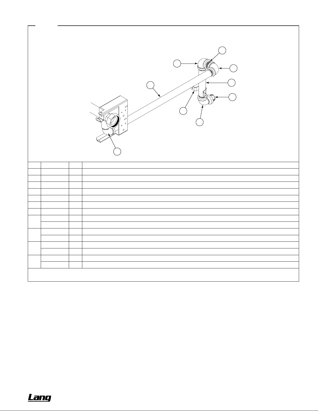
CHEF SERIES SECTIONAL RANGE SERVICE
Figure 31
Gas Connection Parts
5
Key Part Number Qty Description
1 1147005 1
2 1146905 2
3 1163489 1
4 1184777 1
5 1146808 1
6 1174747 1
7 1146911 1
** 4450009 *
4450010 *
** 1167782 *
1167783 *
** 4450008 *
4450007 *
** 1130195 *
1130194 *
1" PIPE CAP
1" 90 DEGREE ELBOW
REAR GAS STUB
STRAP, 1-1/4" PIPE
1" PIPE NIPPLE
TAIL PIPE
ELBOW, ST., BLK, 1" 90 DEGREE
PRESSURE REGULATOR 1-1/4" 2,500,000 BTU NAT
PRESSURE REGULATOR 1-1/4" 2,500,000 BTU LP
PRESSURE REGULATOR 1" 600,000 BTU NAT
PRESSURE REGULATOR 1" 600,000 BTU LP
1-1/4" GAS SHUT OFF VALVE
1" GAS SHUT OFF VALVE
1" QUICK DISCONNECT, 48" FLEX HOSE
1" QUICK DISCONNECT, 60" FLEX HOSE
* Quantity varies.
** Not shown on drawing.
2
2
6
3
1
4
2
7
OWNER’S MANUAL 1192040 REV 1 (01/10) PAGE 55 OF 76
Page 56

SERVICE CHEF SERIES SECTIONAL RANGE
Griddle External and Structural Parts
See drawing on following page.
Key Part Number
1 1192000 1 2 3 4
2 1192024 1 2 3 4
3 1184653 1 - - -
1184657 1 - - 1184651 - 1 - 1184518 - 1 - 1174655 - 1 - 1184516 - 1 - 1184601 - - 1 1183963 - - 1 1184602 - - 1 1183962 - - 1 1184600 - - 1 1183961 - - 1 1185380 - - - 1
1185393 - - - 1
1185385 - - - 1
1185393 - - - 1
1185386 - - - 1
1185395 - - - 1
4 1192111 1 1 1 1
5 1183691 1 1 1 1
6 1184773 1 2 3 4
7 1183897 2 - - -
1183896 - 2 - -
1183524 - - 2 -
1183895 - - - 2
8 1183903 1 - - -
1183902 - 1 - -
1183653 - - 1 -
1185387 - - - 1
9 1183685 - 1 2 3
10 1183891 1 - - -
1183890 - 1 - -
1183635 - - 1 -
1183889 - - - 1
11 1183894 1 - - -
1183893 - 1 - -
1183590 - - 1 -
1183892 - - - 1
12 1146383 - 2 3 4
13 1183692 - 2 3 4
14 1184944 1 - - -
1183784 - 1 - -
1183785 - - 1 -
1185378 - - - 1
1183783 - 1 - -
1183656 - - 1 -
1185464 - - - 1
* Quantity of part used may depend on width of section (12", 24", 36" or 48").
Quantity*
12" 24" 36" 48"
Description
KNOB
KNOB and BEZEL ASM
VALVE PANEL, 12C-G, SS
VALVE PANEL, 12N-G, SS
VALVE PANEL, 24C-GG, SS
VALVE PANEL, 24C-TT, SS
VALVE PANEL, 24N-GG, SS
VALVE PANEL, 24N-TT, SS
VALVE PANEL, 36A/D-GGG, SS
VALVE PANEL, 36A/D-TTT, SS
VALVE PANEL, 36C-GGG, SS
VALVE PANEL, 36C-TTT, SS
VALVE PANEL, 36N-GGG, SS
VALVE PANEL, 36N-TTT, SS
VALVE PANEL, 48A/D-GGGG, SS
VALVE PANEL, 48A/D-TTTT, SS
VALVE PANEL, 48C-GGGG, SS
VALVE PANEL, 48C-TTTT, SS
VALVE PANEL, 48N-GGGG, SS
VALVE PANEL, 48N-TTTT, SS
GREASE DRAWER W/A
GREASE DRAWER BASE W/A
COVER, VALVE SHIELD
BURNER REST, 12 CHAR/GRI
BURNER REST, 24 CHAR/GRI
BURNER REST, 36 CHAR/GRI
BURNER REST, 48 CHAR/GRI
SHIELD, 12" GRIDDLE HEAT
SHIELD, 24" GRIDDLE HEAT
SHIELD, 36" GRIDDLE HEAT
SHIELD, 48" GRIDDLE HEAT
BURNER BOX DIVIDER
TRIM, CHAR/GRI 12 FLUE RISER
TRIM, CHAR/GRI 24 FLUE RISER
TRIM, CHAR/GRI 36 FLUE RISER
TRIM, CHAR/GRI 48 FLUE RISER
TRIM, 42 DEEP CHAR/GRI 12 FLUE RISER
TRIM, 42 DEEP CHAR/GRI 24 FLUE RISER
TRIM, 42 DEEP CHAR/GRI 36 FLUE RISER
TRIM, 42 DEEP CHAR/GRI 48 FLUE RISER
BOLT, HEX, 5/16-18X5LG. (thermostatic griddles only)
SHIELD, T'STAT BULB (thermostatic griddles only)
GRIDDLE W/A, 12 STANDARD
GRIDDLE W/A, 24 STANDARD
GRIDDLE W/A, 36 STANDARD
GRIDDLE W/A, 48 STANDARD
GRIDDLE W/A, 24 T-STAT
GRIDDLE W/A, 36 T-STAT
GRIDDLE W/A, 48 T-STAT
PAGE 56 OF 76 OWNER’S MANUAL 1192040 REV 1 (01/10)
Page 57
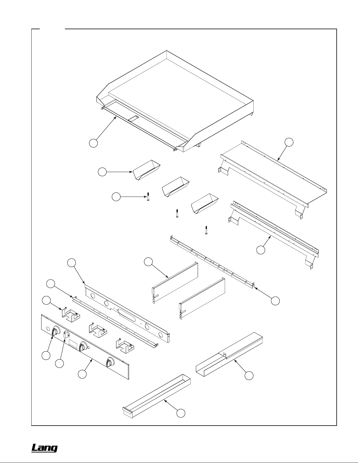
CHEF SERIES SECTIONAL RANGE SERVICE
Figure 32
Griddle External and Structural Parts
See parts list on previous page.
14
11
13
12
10
8
9
7
6
7
1
2
3
4
5
OWNER’S MANUAL 1192040 REV 1 (01/10) PAGE 57 OF 76
Page 58

SERVICE CHEF SERIES SECTIONAL RANGE
Thermostatic Griddle Gas Train Parts
See drawing on following page.
Key Part Number
1 1183919 1 - -
1183675 - 1 -
1183921 - - 1
2 1183925 1 - -
1183545 - 1 -
1185392 - - 1
3 1183549 1 1 2
4 1183550 1 1 2
5 1160008 1 1 2
6 1182594 1 1 2
7 1185389 1 - -
1183682 - 1 -
1185390 - - 1
8 1176385 2 3 4
9 1174542 2 3 4
10 1182553 2 3 4
11 1183503 2 3 4
12 1183680 2 3 4
** 1008748 4 6 8
1008756 4 6 8
13 1182762 4 6 8
14 1184540 1 1 2
15 1164085 1 1 2
16 1184541 1 1 2
17 1183687 1 1 2
18 1183681 1 1 2
19 1182580 1 1 2
20 1183573 1 2 2
21 1183584 1 2 2
22 1183536 1 2 2
Quantity*
24" 36" 48"
Description
MANIFOLD W/A, 24, CHAR/GRI SECT
MANIFOLD W/A, 36, CHAR/GRI SECT
MANIFOLD W/A, 48, CHAR/GRI SECT
SUPPORT, 24 THERMOSTAT
SUPPORT, 36 THERMOSTAT
SUPPORT, 48 THERMOSTAT
VALVE, 200K BURNER
TUBE, ON/OFF VALVE GAS
ELBOW, BRASS
SAFETY VALVE SINGLE
MANIFOLD, T'STAT GRIDDLE FEEDER 24
MANIFOLD, T'STAT GRIDDLE FEEDER 36
MANIFOLD, T'STAT GRIDDLE FEEDER 48
FITTING, STRAIGHT
TUBE, T-GRID MANIFOLD TO T'STAT
SNAP ACTION GRIDDLE THERMOSTAT
TUBE, 3/8" X 9" FLEXIBLE
MANIFOLD, DUAL BURNER ORIFICE
ORIFICE, NAT GAS (if appliance will operate above 2000 ft, contact Lang for appropriate orifice size)
ORIFICE, PROPANE (if appliance will operate above 2000 ft, contact Lang for appropriate orifice size)
BURNER ASSEMBLY, CHARBROILER
TUBE, T-GRID LT PILOT ADJUST
VALVE ASM, PILOT
TUBE, T-GRID RT PILOT ADJUST
ASSEMBLY, PILOT SHIELD
BRACKET, PILOT
THERMOCOUPLE, 24 IN
TUBE, RUNNER TUBE ORIFICE
FITTING, NAT 3/8 REDUCER
TUBE ASSEMBLY, PILOT RUNNER
* Quantity of part used may depend on width of section (24", 36" or 48").
** Not shown on drawing.
PAGE 58 OF 76 OWNER’S MANUAL 1192040 REV 1 (01/10)
Page 59
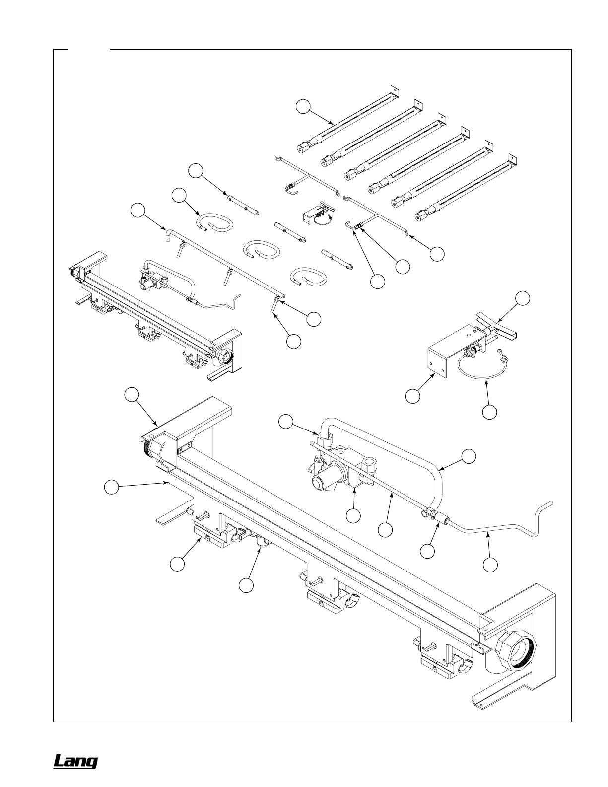
CHEF SERIES SECTIONAL RANGE SERVICE
Figure 33
Thermostatic Griddle Gas Train Parts
See parts list on previous page.
13
12
11
7
22
21
20
17
8
9
1
18
19
5
4
2
6
14
15
10
16
3
OWNER’S MANUAL 1192040 REV 1 (01/10) PAGE 59 OF 76
Page 60

SERVICE CHEF SERIES SECTIONAL RANGE
Uniform Hot-Top Parts
See drawing on following page.
Key Part Number
1 1192000 1 2 3
2 1184737 1 - -
1184739 1 - -
1184933 - 1 -
1184735 - 1 -
1184611 - - 1
1184612 - - 1
1184613 - - 1
3 1184546 2 4 6
4 1184551 - 1 2
5 1183505 1 2 3
6 1184545 - 1 2
7 1183888 1 - -
1184555 - 1 -
1184544 - - 1
8 1183900 1 - -
1184567 - 1 -
1184566 - - 1
9 1183563 - 1 2
10 1184547 1 2 3
11 1183515 1 2 3
12 1183920 1 - -
1183919 - 1 -
1183675 - - 1
13 1179222 1 2 3
14 1176008 1 2 3
15 1183680 1 2 3
16 1183503 1 2 3
** 1008750 2 4 6
1008756 2 4 6
17 1182762 2 4 6
18 1166004 1 2 3
19 1184505 1 2 3
20 1184506 1 2 3
21 1182821 2 4 6
Quantity*
12" 24" 36"
Description
KNOB
VALVE PANEL, 12C-H, SS
VALVE PANEL, 12N-H, SS
VALVE PANEL, 24C-HH, SS
VALVE PANEL, 24N-HH, SS
VALVE PANEL, 36A/D-HHH, SS
VALVE PANEL, 36C-HHH, SS
VALVE PANEL, 36N-HHH, SS
BURNER REST, HOT TOP
COVER, BATTERY CENTER
BURNER BOX BOTTOM, 12
COVER, HOT TOP DIVIDER REAR
TRIM, HOT TOP 12 FLUE RISER
TRIM, HOT TOP 24 FLUE RISER
TRIM, HOT TOP 36 FLUE RISER
TRIM, HOT TOP 42 DEEP 12 FLUE RISER
TRIM, HOT TOP 42 DEEP 24 FLUE RISER
TRIM, HOT TOP 42 DEEP 36 FLUE RISER
TRIM, CENTER
SHIELD, HOT TOP HEAT
PLATE, UNIFORM HEATED TOP
MANIFOLD W/A, 12 UNIFORM H/TOP
MANIFOLD W/A, 24 UNIFORM H/TOP
MANIFOLD W/A, 36 UNIFORM H/TOP
NIPPLE, EXTENSION
VALVE, BURNER, NAT
MANIFOLD, DUAL BURNER ORIFICE
TUBE, 3/8" X 9" FLEXIBLE
ORIFICE, NAT GAS (if appliance will operate above 2000 ft, contact Lang for appropriate orifice size)
ORIFICE, PROPANE (if appliance will operate above 2000 ft, contact Lang for appropriate orifice size)
BURNER ASSEMBLY, CHARBROILER
FITTING, DOUBLE PILOT, 3/16" TUBE
TUBE W/A, CHAR. LEFT PILOT
TUBE W/A, CHAR. RIGHT PILOT
BRACKET, PILOT
* Quantity of part used may depend on width of section (12", 24", or 36").
** Not shown on drawing.
PAGE 60 OF 76 OWNER’S MANUAL 1192040 REV 1 (01/10)
Page 61
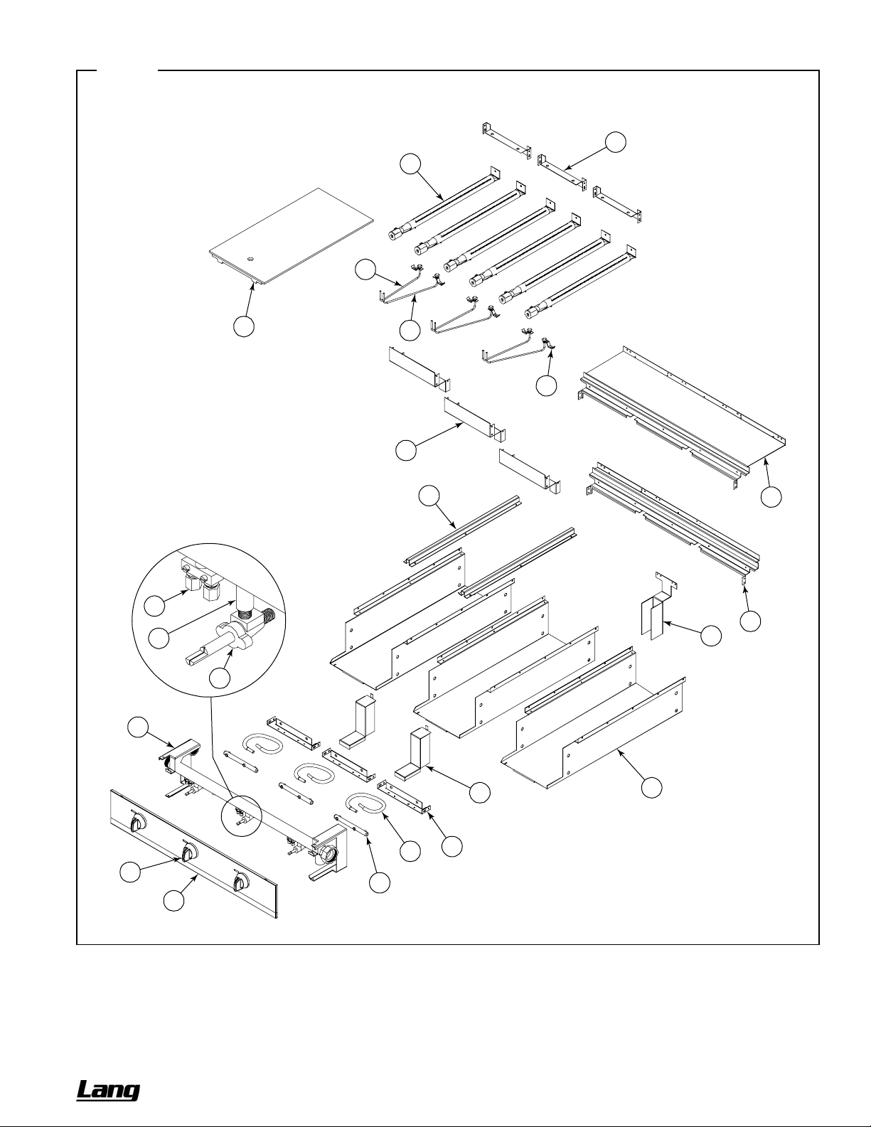
CHEF SERIES SECTIONAL RANGE SERVICE
Figure 34
Uniform Hot-Top Parts
See parts list on previous page.
3
17
19
12
18
13
14
11
20
21
10
9
8
7
6
4
16
1
15
3
5
2
OWNER’S MANUAL 1192040 REV 1 (01/10) PAGE 61 OF 76
Page 62

SERVICE CHEF SERIES SECTIONAL RANGE
Graduated-Hot-Top Parts
See drawing on following page.
Key Part Number Qty Description
1 1192000 1
2 1184617 1
1184618 1
1184619 1
3 1183531 1
4 1183589 1
5 1183957 2
6 1183959 2
7 1183956 1
8 1183516 2
9 1018997 1
10 1018996 1
11 1183675 1
12 1176008 1
13 1183960 1
* 1006425 1
1006443 1
14 1884 1
15 1160293 1
16 1099002 1
17 1164199 1
18 1183964 1
19 1038099 1
* Not shown on drawing.
KNOB
VALVE PANEL, 36A/D-GRAD, SS (oven base)
VALVE PANEL, 36C-GRAD, SS (cabinet base)
VALVE PANEL, 36N-GRAD, SS (modular-countertop base)
TRIM, 36 FLUE RISER
TRIM, 42 DEEP 36 FLUE RISER
BURNER REST, GRADUATED
BRACKET, BURNER HOLD DOWN
SHIELD, GRADUATED BURNER
PLATE, GRADUATED HEAT TOP
PS, GRIDDLE, CSTIR, RING, GRAD.
PS, GRIDDLE, CSTIR, LID.GRAD.
MANIFOLD W/A, GRADUATED H/TOP
BURNER VALVE, NAT
BRACKET, BURNER ORFICE
ORIFICE, NAT GAS (if appliance will operate above 2000 ft, contact Lang for appropriate orifice size)
ORIFICE, PROPANE (if appliance will operate above 2000 ft, contact Lang for appropriate orifice size)
HOT TOP BRNR ASM
BAFFLE, TOP BURNER AIR
PILOT ADJUST
TUBE, PILOT
BRACKET, PILOT ASSEMBLY
ASSEMBLY, PILOT
PAGE 62 OF 76 OWNER’S MANUAL 1192040 REV 1 (01/10)
Page 63
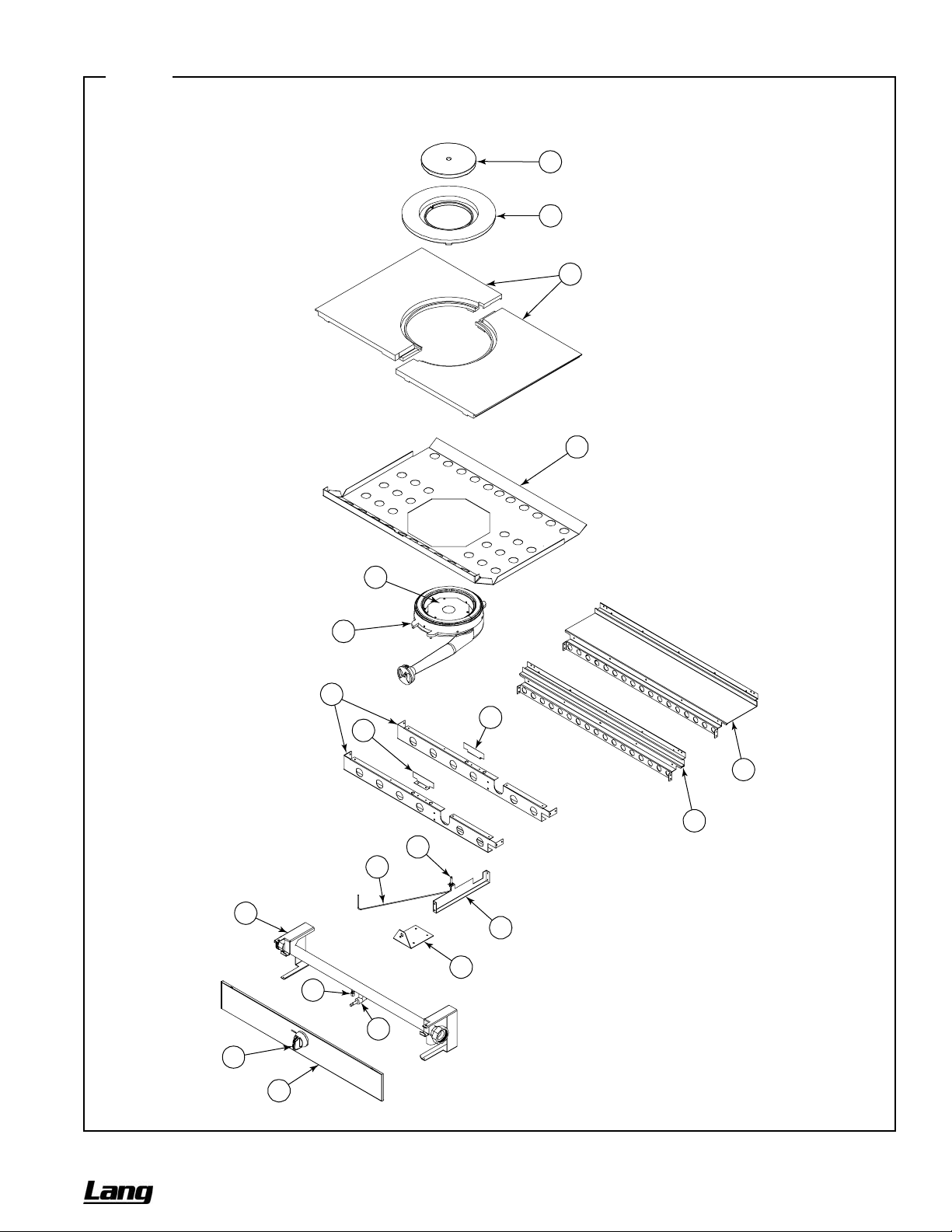
CHEF SERIES SECTIONAL RANGE SERVICE
Figure 35
Graduated-Hot-Top Parts
See parts list on previous page.
10
9
8
7
15
14
5
6
6
4
3
19
17
11
18
13
16
12
1
2
OWNER’S MANUAL 1192040 REV 1 (01/10) PAGE 63 OF 76
Page 64

SERVICE CHEF SERIES SECTIONAL RANGE
Oven Base Parts
See drawing on following page.
Key Part Number Qty Description
1 1180776 1
2 1180528 2
3 6660 8
* 1173545 1
1179920 1
4 1192013 1
* 1192010 1
* 1192011 1
* 1192012 1
5 1190501 1
* 1189786 1
* 1189788 2
* 1183575 1
6 1186547 1
7 1189817 1
8 1177567 1
9 1183619 1
10 1183551 1
11 1183618 1
12 1166129 1
13 1165783 1
14 1179710 1
15 1183683 1
16 1183574 1
17 1190511 1
18 1176099 1
19 1006299 1
20 1190520 1
21 1184417 1
22 1183585 1
23 1188768 1
24 1187476 1
25 1183568 1
* 1008730 1
1008748 1
26 1182072 1
27 1183567 1
28 1187994 1
* Not shown on drawing.
OVEN BOTTOM\FLAME
RACK_GUIDE CO BASE
CLIP, RACK SUPPORT
OVEN RACK (for standard oven)
OVEN RACK (for convection oven)
ASM, CONTROL PANEL, CO, ELECTRONIC IGNITION
ASM, CONTROL PANEL, STANDING PILOT
ASM, CONTROL PANEL, CO, STANDING PILOT
ASM, CONTROL PANEL, ELECTRONIC IGNITION
ASSEMBLY, OVEN DOOR
ASM, DOOR HINGE LEFT
ASM, DOOR HINGE RIGHT
KICK PANEL
OVEN DOOR SPRING
CHAIN ASSEMBLY
DOOR SWITCH
DOOR SWITCH BRACKET
BRACKET ASSEMBLY, ROLLER ASM
PULLEY BRACKET
DOOR CHAIN PULLEY
DOOR SPROCKET BUSHING
SPACER
DOOR PULLEY PIN
1/8" DIA X 1" COTTER PIN ZINC
IGNITION MODULE ASM
VALVE, BURNER
ELBOW, 1/2CC X 3/8M F
PLUG
TUBE, OVEN GAS SUPPLY
SOLENOID VALVE ASM, 120V/60 (for units with electronic ignition)
COMBINATION VALVE (for units with a standing pilot)
TUBE, FLEX 3/8" X 4"
BRACKET, ORIFICE
ORIFICE, NAT GAS (if appliance will operate above 2000 ft, contact Lang for appropriate orifice size)
ORIFICE, PROPANE (if appliance will operate above 2000 ft, contact Lang for appropriate orifice size)
BRACKET, OVEN BURNER
BURNER AND PILOT ASM, OVEN (for units with electronic ignition)
BURNER AND PILOT ASM, OVEN (for units with standing pilot)
PAGE 64 OF 76 OWNER’S MANUAL 1192040 REV 1 (01/10)
Page 65
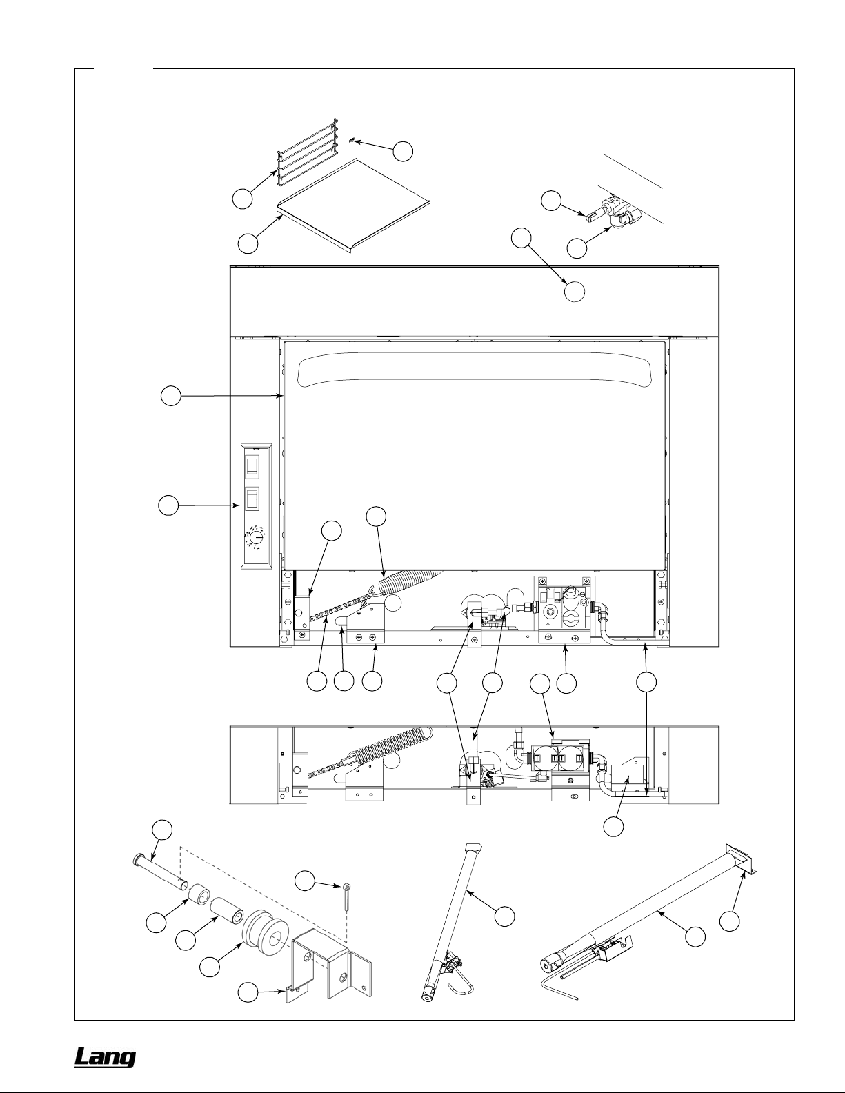
CHEF SERIES SECTIONAL RANGE SERVICE
Figure 36
Oven Base Parts
See parts list on previous page.
2
1
5
4
10
Oven-Gas Shut-Off Valve is
3
6
Located Behind Valve Panel
18
20
19
Standing Pilot
Parts
Electronic Ignition
Parts
14
15
Roller Assembly Parts
13
12
11
16
97
8
25
24
Standing-Pilot
Burner Assembly
28
22
23
21
17
26
27
Electronic-Ignition
Burner Assembly
OWNER’S MANUAL 1192040 REV 1 (01/10) PAGE 65 OF 76
Page 66
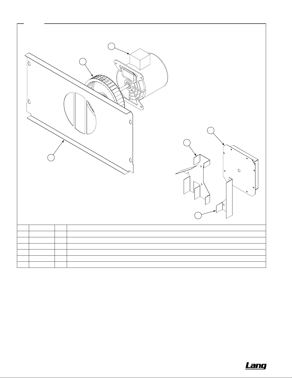
SERVICE CHEF SERIES SECTIONAL RANGE
Figure 37
Convection Oven Blower Parts
3
2
4
5
1
Key Part Number Qty Description
1 1180834 1
2 1177581 1
3 1177452 1
4 1180821 1
5 1181747 1
6 1181748 1
OVEN BAFFLE CO
BLOWER WHEEL ASSEMBLY
MOTOR, 1/3 HP, 115 VOLT
POCKET W/A, BLOWER, 500 SERIES
SHIELD, RT BLOWER, 500 SERIES
SHIELD, LT BLOWER, 500 SERIES
6
PAGE 66 OF 76 OWNER’S MANUAL 1192040 REV 1 (01/10)
Page 67
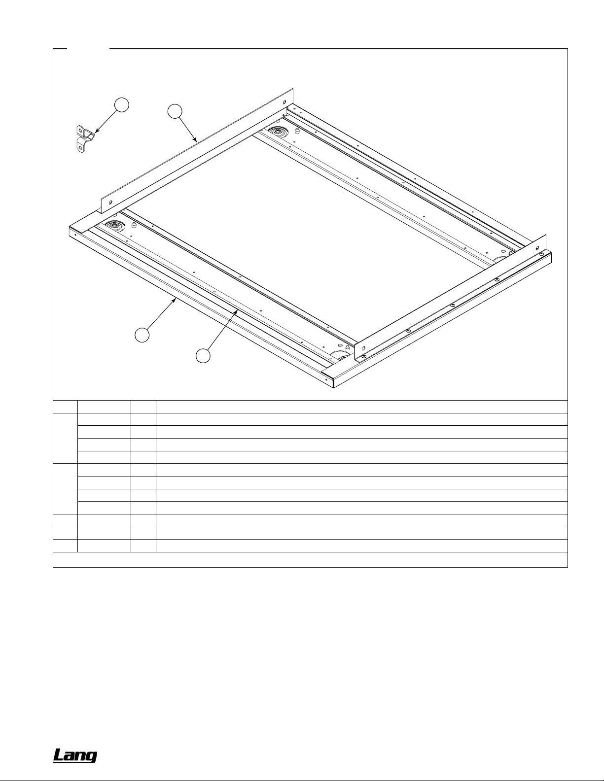
CHEF SERIES SECTIONAL RANGE SERVICE
Figure 38
Modular-Countertop Base Parts
4
3
1
2
Key Part Number Qty Description
1 1183863 1
1183859 1
1183523 1
1185418 1
2 1183861 2
1183858 2
1183579 2
1185413 2
3 1183640 2
4 1164132 2
* 1164133 2
BASE. 12 COUNTERTOP
BASE. 24 COUNTERTOP
BASE. 36 COUNTERTOP
BASE. 48 COUNTERTOP
STIFFENER, 12 BASE
STIFFENER, 24 BASE
STIFFENER, 36 BASE
STIFFENER, 48 BASE
RETAINER, MODULAR TOP
STRIKER (for valve panel)
CATCH (for valve panel)
* Not shown on drawing.
OWNER’S MANUAL 1192040 REV 1 (01/10) PAGE 67 OF 76
Page 68

SERVICE CHEF SERIES SECTIONAL RANGE
Cabinet-Base Parts
See drawing on following page.
Key Part Number
1 1184954 1 - - -
1184952 - 1 - 2
1183598 - - 1 -
2 1184955 1 - - -
1184953 - 1 - 2
1183599 - - 1 -
3 1183875 1 - - -
1183873 - 1 - 2
1183600 - - 1 4 1183563 - - 1 5 1183866 1 - - -
1183864 - 1 - 2
1183586 - - 1 6 1183869 1 - - -
1183867 - 1 - 2
1183587 - - 1 7 1183872 1 - - -
1183870 - 1 - 2
1183594 - - 1 -
** 1183983 - 1 1 2
** 1183984 - 1 1 2
** 1183985 1 1 1 2
** 1183986 1 1 1 2
Quantity*
12" 24" 36" 48"
Description
CABINET LINING ASM, 12" LT FT
CABINET LINING ASM, 24" LT FT
CABINET LINING ASM, 36" LT FT
CABINET LINING ASM, 12" RT FT
CABINET LINING ASM, 24" RT FT
CABINET LINING ASM, 36" RT FT
CABINET LINING, 12" BOTTOM
CABINET LINING, 24" BOTTOM
CABINET LINING, 36" BOTTOM
TRIM, CENTER
CABINET LINING, 12" LEFT
CABINET LINING, 24" LEFT
CABINET LINING, 36" LEFT
CABINET LINING, 12" RIGHT
CABINET LINING, 24" RIGHT
CABINET LINING, 36" RIGHT
CABINET LINING, 12" BACK
CABINET LINING, 24" BACK
CABINET LINING, 36" BACK
HINGE ASSEMBLY, UPPER RIGHT
HINGE ASSEMBLY, LOWER RIGHT
HINGE ASSEMBLY, UPPER LEFT
HINGE ASSEMBLY, LOWER LEFT
* Quantity of part used may depend on width of section (12", 24", 36" or 48").
** Not shown on drawing.
PAGE 68 OF 76 OWNER’S MANUAL 1192040 REV 1 (01/10)
Page 69
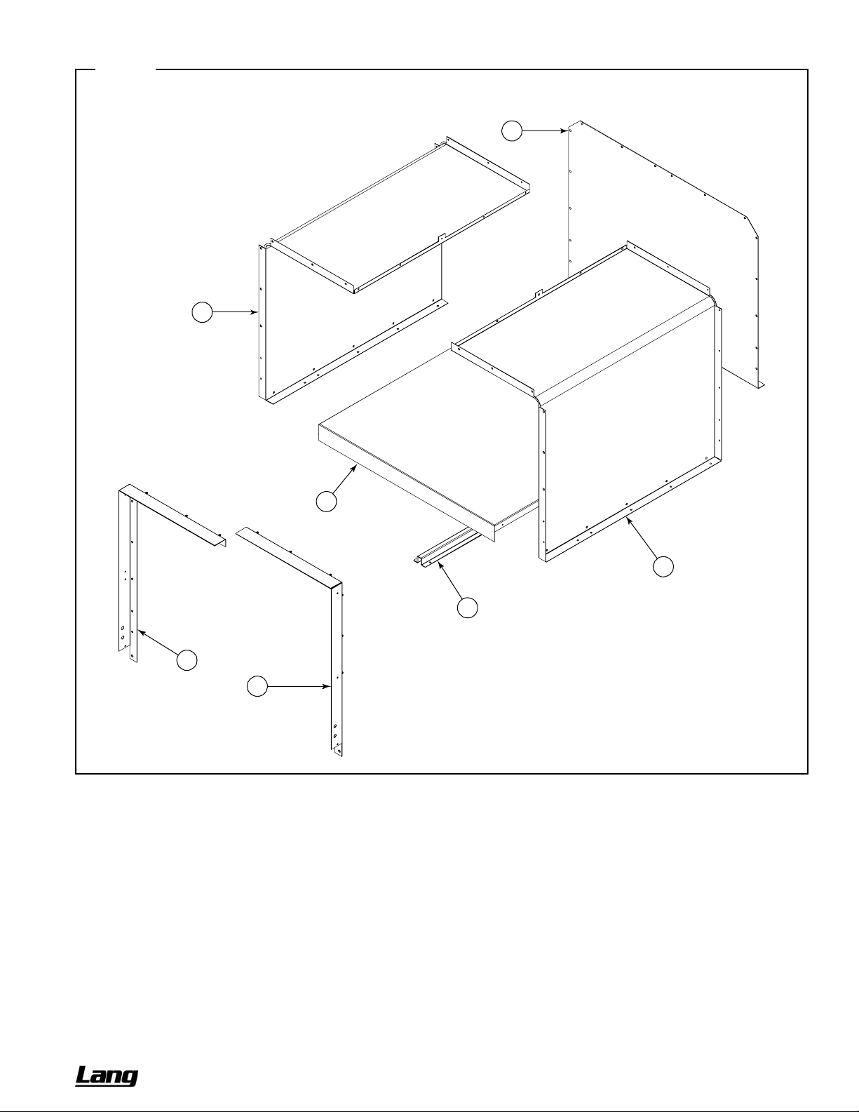
CHEF SERIES SECTIONAL RANGE SERVICE
Figure 39
Cabinet-Base Parts
See parts list on previous page.
5
7
3
6
4
1
2
OWNER’S MANUAL 1192040 REV 1 (01/10) PAGE 69 OF 76
Page 70

SERVICE CHEF SERIES SECTIONAL RANGE
Flue Riser Parts
See drawing on following page.
For continuous flue risers spanning multiple sections, or sloped enclosures, contact Lang.
Key Part Number Qty Description
1 1183617 1
2 1183526 1
1183527 1
3 1183528 1
1183529 1
** 1184917 *
1184918 *
1184687 *
1184919 *
4 1183791 1
1183793 1
1183530 1
1183795 1
1183801 1
1183803 1
1183851 1
1183805 1
1184901 1
1184902 1
1184903 1
1184904 1
1184901 1
1184902 1
1184903 1
1184904 1
1183811 1
1183813 1
1183852 1
1183815 1
1184907 1
1184908 1
1184909 1
1184910 1
1184907 1
1184908 1
1184909 1
1184910 1
5 1183821 1
1184785 1
1183823 1
1184786 1
1183684 1
1184791 1
1183825 1
1184792 1
Table continues on next page.
* Each tubed shelf has seven tubes.
** Not shown on drawing.
FLUE BOX ASSEMBLY, 36" (for models with an oven base)
BRACKET, 36 DEEP LT FLUE RISER
BRACKET, 36 DEEP RT FLUE RISER
BRACKET, 42 DEEP LT FLUE RISER
BRACKET, 42 DEEP RT FLUE RISER
TUBE 12 (single tube for 12"-wide tubed shelves)
TUBE 24 (single tube for 24"-wide tubed shelves)
TUBE 36 (single tube for 36"-wide tubed shelves)
TUBE 48 (single tube for 48"-wide tubed shelves)
SPLASHER, 5" X 12"
SPLASHER, 5" X 24"
SPLASHER, 5" X 36"
SPLASHER, 5" X 48"
SPLASHER, 24" X 12" (without shelf)
SPLASHER, 24" X 24" (without shelf)
SPLASHER, 24" X 36" (without shelf)
SPLASHER, 24" X 48" (without shelf)
SPLASHER, 24" X 12" (with solid shelf)
SPLASHER, 24" X 24" (with solid shelf)
SPLASHER, 24" X 36" (with solid shelf)
SPLASHER, 24" X 48" (with solid shelf)
SPLASHER, 24" X 12" (with tubed shelf)
SPLASHER, 24" X 24" (with tubed shelf)
SPLASHER, 24" X 36" (with tubed shelf)
SPLASHER, 24" X 48" (with tubed shelf)
SPLASHER, 36" X 12" (without shelves)
SPLASHER, 36" X 24" (without shelves)
SPLASHER, 36" X 36" (without shelves)
SPLASHER, 36" X 48" (without shelves)
SPLASHER, 36" X 12" (with solid shelves)
SPLASHER, 36" X 24" (with solid shelves)
SPLASHER, 36" X 36" (with solid shelves)
SPLASHER, 36" X 48" (with solid shelves)
SPLASHER, 36" X 12" (with tubed shelves)
SPLASHER, 36" X 24" (with tubed shelves)
SPLASHER, 36" X 36" (with tubed shelves)
SPLASHER, 36" X 48" (with tubed shelves)
SHIELD, 5" X 12" WALL AZ
SHIELD, 5" X 12" WALL SS
SHIELD, 5" X 24" WALL AZ
SHIELD, 5" X 24" WALL SS
SHIELD, 5" X 36" WALL AZ
SHIELD, 5" X 36" WALL SS
SHIELD, 5" X 48" WALL AZ
SHIELD, 5" X 48" WALL SS
PAGE 70 OF 76 OWNER’S MANUAL 1192040 REV 1 (01/10)
Page 71
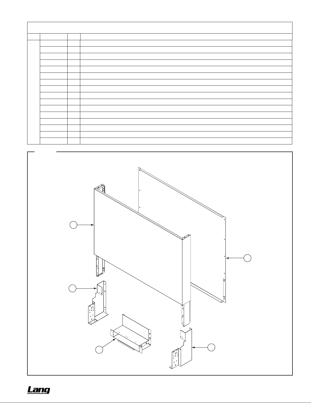
CHEF SERIES SECTIONAL RANGE SERVICE
Flue Riser Parts (continued)
Key Part Number Qty Description
5 1183831 1
1184793 1
1183833 1
1184794 1
1183853 1
1184795 1
1183835 1
1184796 1
1183841 1
1184797 1
1183843 1
1184798 1
1183854 1
1184799 1
1183845 1
1184900 1
Figure 40
SHIELD, 24" X 12" WALL AZ
SHIELD, 24" X 12" WALL SS
SHIELD, 24" X 24" WALL AZ
SHIELD, 24" X 24" WALL SS
SHIELD, 24" X 36" WALL AZ
SHIELD, 24" X 36" WALL SS
SHIELD, 24" X 48" WALL AZ
SHIELD, 24" X 48" WALL SS
SHIELD, 36" X 12" WALL AZ
SHIELD, 36" X 12" WALL SS
SHIELD, 36" X 24" WALL AZ
SHIELD, 36" X 24" WALL SS
SHIELD, 36" X 36" WALL AZ
SHIELD, 36" X 36" WALL SS
SHIELD, 36" X 48" WALL AZ
SHIELD, 36" X 48" WALL SS
Flue Riser Parts
See parts list that begins on previous page.
4
3
5
1
2
OWNER’S MANUAL 1192040 REV 1 (01/10) PAGE 71 OF 76
Page 72

SERVICE CHEF SERIES SECTIONAL RANGE
Side Panel and Battery-Assembly Parts
Part Number Description
1183547
1183563
1183564
1183532
1183521
1184558
1184559
1184573
1184557
1184574
1184560
1183671
1183672
1183538
1183553
1184564
1184565
1183673
1183674
1184778
1184779
1183657
1183658
1183661
1183670
1183669
1183666
1183662
1183665
TRIM, SIDE (if side is not adjacent to another section of a battery)
TRIM, SIDE (if side is adjacent to an open-burner section of a battery)
TRIM, SIDE (if side is adjacent to a griddle or charbroiler section of a battery)
BODY SIDE, 36 SS RT
BODY SIDE, 36 SS LT
BODY SIDE, 36 SS OPEN RT
BODY SIDE, 36 SS OPEN LT
BODY SIDE, 36 CAB SS RT
BODY SIDE, 36 CAB SS LT
BODY SIDE, 36 CAB SS OPEN RT
BODY SIDE, 36 CAB SS OPEN LT
BODY SIDE, HALF AZ RT
BODY SIDE, HALF AZ LT
BODY SIDE, SS COUNTERTOP RT
BODY SIDE, SS COUNTERTOP LT
BODY SIDE, SS OPEN COUNTERTOP RT
BODY SIDE, SS OPEN COUNTERTOP LT
BODY SIDE, HALF AZ COUNTERTOP RT
BODY SIDE, HALF AZ COUNTERTOP LT
PLATE, FT/RR BATTERY CONNECT
PLATE, RISER BATTERY CONNECT
TRIM, FRONT 36 OVN-36 OVN
TRIM, FRONT 36 OVN-36 CAB
TRIM, FRONT 36 OVN-CAB
TRIM, FRONT 36 CAB-36 OVN
TRIM, FRONT 36 CAB-36 CAB
TRIM, FRONT 36 CAB-CAB
TRIM, FRONT CAB-36 OVN
TRIM, FRONT CAB-CAB
PAGE 72 OF 76 OWNER’S MANUAL 1192040 REV 1 (01/10)
Page 73

CHEF SERIES SECTIONAL RANGE
Notes:
OWNER’S MANUAL 1192040 REV 1 (01/10) PAGE 73 OF 76
Page 74

CHEF SERIES SECTIONAL RANGE
Notes:
PAGE 74 OF 76 OWNER’S MANUAL 1192040 REV 1 (01/10)
Page 75

CHEF SERIES SECTIONAL RANGE
Notes:
OWNER’S MANUAL 1192040 REV 1 (01/10) PAGE 75 OF 76
Page 76
CHEF SERIES SECTIONAL RANGE
CHEF SERIES
SECTIONAL RANGE
A product with the Lang name incorporates the best in durability and low maintenance. We all recognize, however,
that replacement parts and occasional professional service may be necessary to extend the useful life of this
appliance. When service is needed, contact a Lang Authorized Service Agency, or your dealer. To avoid
confusion, always refer to the model number, serial number, and type of your appliance.
Lang Manufacturing International, Inc.
10 Sunnen Drive, St. Louis, MO 63143
Phone: (800) 807-9054 Fax: (314) 781-2714
www.langworld.com
PAGE 76 OF 76 OWNER’S MANUAL 1192040 REV 1 (01/10)
 Loading...