

Page 1
Installation,
Operations, and
Maintenance Instructions
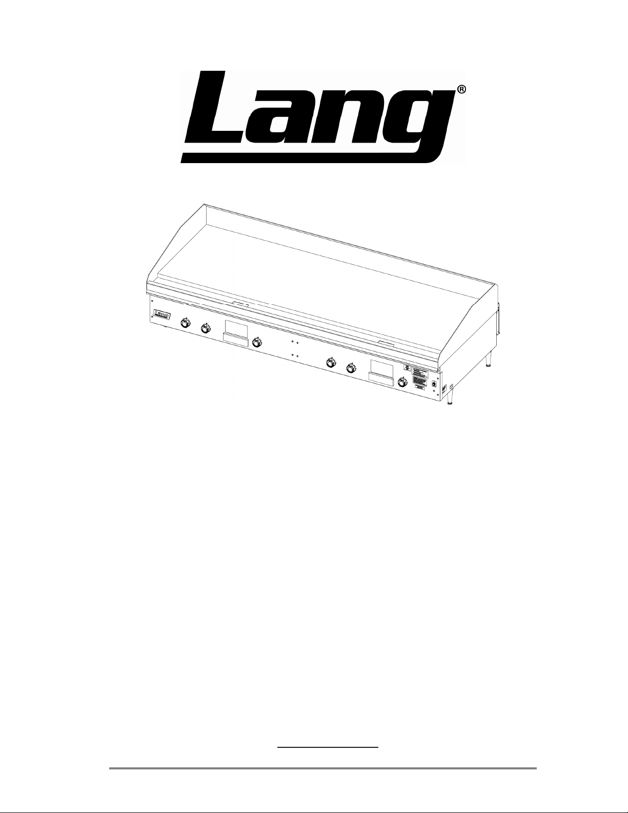
Gas Griddle, Spark Ignition, “ACCU-TEMP”
Model:
224T 224TH 224THG 224SHG 224THE
236T 236THE 236THG
248T 248TC 248TCHE 248THE 248THG
260T 260TC 260TCHG 260THE 260THG
272T 272THG 272TNTS
Star Manufacturing International 10 Sunnen Drive St. Louis, MO 63143
Part Number: 2M-W358 Phone: 800-438-5264 Fax: 314-781-2714
Rev. F WWW.STAR-MFG.COM
October 14, 2010
Page 2

THIS MANUAL MUST BE RETAINED FOR FUTURE REFERENCE.
READ, UNDERSTAND AND FOLLOW THE INSTRUCTIONS AND
WARNINGS CONTAINED IN THIS MANUAL.
FOR YOUR SAFETY
DO NOT STORE OR USE GASOLINE OR OTHER FLAMMABLE
VAPORS AND LIQUIDS IN THE VICINITY OF THIS OR ANY
OTHER APPLIANCE.
POST IN A PROMINENT LOCATION
WARNING: IMPROPER INSTALLATION, ADJUSTMENT,
ALTERATION, SERVICE OR MAINTENANCE CAN CAUSE
PROPERTY DAMAGE, INJURY OR DEATH. READ THE
INSTALLATION, OPERATING AND MAINTENANCE
INSTRUCTIONS THOROUGHLY BEFORE INSTALLING OR
SERVICING THIS EQUIPMENT.
IMPORTANT
The installation of the Appliance should conform to the NATIONAL FUEL
GAS CODE "ANSI Z223.1/NFPA 54 - LATEST EDITION" AND ALL LOCAL
GAS COMPANY RULES AND REGULATIONS.
IN CANADA INSTALLATION SHALL BE IN ACCORDANCE WITH THE
CURRENT CAN/CGA-B149.1 NATURAL GAS INSTALLATION CODE OR
CAN/CGA-B149.2 PROPANE INSTALLATION CODE AND LOCAL CODES
WHERE APPLICABLE.
Model #: Purchased From:
Serial #: Location:
Date Purchased: Date Installed:
Purchase Order #: For Service, Call:
2
Page 3

TABLE OF CONTENTS
CHAPTER PAGE
1. TABLE OF CONTENTS ...............................................................................3
2. READ FIRST .................................................................................................4
3. EQUIPMENT DESCRIPTION ...................................................................... 6
4. UNPACKING................................................................................................. 8
5. INSTALLATION ........................................................................................... 10
6. GRIDDLE SURFACE CARE ........................................................................ 11
7. CHROME WARRANTY ............................................................................... 12
8. INITIAL START-UP......................................................................................13
9. OPERATION...........................................................................................14 - 15
10. MAINTENANCE & CLEANING PROCEDURES...................................... 16
11. TROUBLESHOOTING ................................................................................. 18
12. PARTS LIST ........................................................................................... 19 - 24
13. WIRING DIAGRAMS............................................................................25 - 26
3
Page 4
IMPORTANT READ FIRST IMPORTANT
CAUTION: THE GRIDDLE EXTREMELY HEAVY. FOR SAFE
HANDLING, INSTALLER SHOULD OBTAIN HELP AS NEEDED, OR
EMPLOY APPROPRIATE MATERIALS HANDLING EQUIPMENT (SUCH
AS A FORKLIFT, DOLLY, OR PALLET JACK) TO REMOVE THE UNIT
FROM THE SKID AND MOVE IT TO THE PLACE OF INSTALLATION.
CAUTION: ANY STAND, COUNTER OR OTHER DEVICE ON
WHICH THE GRIDDLE WILL BE LOCATED MUST BE
DESIGNED TO SUPPORT THE WEIGHT OF THE
GRIDDLE.
CAUTION: SHIPPING STRAPS ARE UNDER TENSION AND CAN
SNAP BACK WHEN CUT.
DANGER: THIS APPLIANCE MUST BE GROUNDED AT THE
TERMINAL PROVIDED. FAILURE TO GROUND THE
APPLIANCE COULD RESULT IN ELECTROCUTION
AND DEATH.
WARNING: INSTALLATION OF THE UNIT MUST BE DONE BY
PERSONNEL QUALIFIED TO WORK WITH
ELECTRICITY AND PLUMBING. IMPROPER
INSTALLATION CAN CAUSE INJURY TO
PERSONNEL AND/OR DAMAGE TO EQUIPMENT.
UNIT MUST BE INSTALLED IN ACCORDANCE WITH
ALL APPLICABLE CODES.
NOTICE: The data plate is located inside the control
compartment of each griddle. The griddle voltage,
serial number, gas specifications, and clearance
specifications are on the data plate. This information
should be carefully read and understood before
proceeding with the installation.
NOTICE: The installation of any components such as a vent
hood, grease extractors, fire extinguisher systems,
must conform to their applicable National, State and
locally recognized installation standards.
WARNING: BEFORE LIGHTING, USE A SOAP AND WATER
SOLUTION TO TEST ALL JOINTS FOR GAS LEAKS.
NOTICE: During the first few hours of operation you may
notice a small amount of smoke coming off the
griddle, and a faint odor from the smoke. This is
normal for a new griddle and will disappear after the
first few hours of use.
CAUTION: ALWAYS KEEP THE AREA NEAR THE APPLIANCE
FREE FROM COMBUSTIBLE MATERIALS.
4
Page 5
IMPORTANT READ FIRST IMPORTANT
CAUTION: KEEP FLOOR IN FRONT OF EQUIPMENT CLEAN AND
DRY. IF SPILLS OCCUR, CLEAN IMMEDIATELY, TO
AVOID THE DANGER OF SLIPS OR FALLS.
WARNING: KEEP WATER AND SOLUTIONS OUT OF CONTROLS.
NEVER SPRAY OR HOSE CONTROL CONSOLE,
ELECTRICAL CONNECTIONS, ETC.
CAUTION: MOST CLEANERS ARE HARMFUL TO THE SKIN, EYES,
MUCOUS MEMBRANES AND CLOTHING.
PRECAUTIONS SHOULD BE TAKEN TO WEAR RUBBER
GLOVES, GOGGLES OR FACE SHIELD AND
PROTECTIVE CLOTHING. CAREFULLY READ THE
WARNING AND FOLLOW THE DIRECTIONS ON THE
LABEL OF THE CLEANER TO BE USED.
NOTICE: Never leave a chlorine sanitizer in contact with stainless
steel surfaces longer than 10 minutes. Longer contact
can cause corrosion.
CAUTION: GRILL CALIBRATION REQUIRES DISASSEMBLY OF
THE THERMOSTAT AND SHOULD BE PERFORMED BY
QUALIFIED PERSONNEL ONLY. IT IS GENERALLY
MORE COST EFFECTIVE TO REPLACE A THERMOSTAT
THAT IS OUT OF CALIBRATION.
NOTICE: Service on this, or any other, LANG appliance must be
performed by qualified personnel only. Consult your
LANG Authorized Service Agent Directory or call the
factory at 1-800-807-9054, or WWW.STAR-MFG.COM
For the service agent near you.
WARNING: BOTH HIGH AND LOW VOLTAGES ARE PRESENT
INSIDE THIS APPLIANCE WHEN THE UNIT IS
PLUGGED/WIRED INTO A LIVE RECEPTACLE. BEFORE
REPLACING ANY PARTS, DISCONNECT THE UNIT
FROM THE ELECTRIC POWER SUPPLY.
CAUTION: USE OF ANY REPLACEMENT PARTS OTHER THAN
THOSE SUPPLIED BY LANG OR THEIR AUTHORIZED
DISTRIBUTORS CAN CAUSE BODILY INJURY TO THE
OPERATOR AND DAMAGE TO THE EQUIPMENT AND
WILL VOID ALL WARRANTIES.
5
Page 6

EQUIPMENT DESCRIPTION
Lang Model: 200 Series “AccuTemp” Griddles
3.1 Exterior Construction
• The griddle dimensions are 17” (43.18cm) High, 30” (76.20cm) Deep, and
width is dependent on the actual model number.
• The Sides, Bottom, and Rear wall are constructed of double wall stainless
steel, which allows closer installation to combustible surfaces.
• The griddle surface is made of 1” thick, highly polished steel to reduce hot
and cold spots, recovery problems, warping, and ensure even heat to the
edges of the griddle.
3.2 Operation
• Each twelve-inch section has its own snap-action thermostat and gas valves
that are fully on or fully off.
3.3 Controls
• The ACCU-TEMP Griddle comes with thermostat controls.
3.4 Technical
• Griddle operates on either Natural gas or Propane. This must be specified
when ordering. It is shipped with a Power Cord and Plug attached.
• Floor space required is 30” (76.20cm) Deep, and width is 2 ft, 3ft, 4ft, 5ft, or
6ft depending on actual model number.
• The griddle weighs 260, 390, 520, 650, 780 lbs. depending on actual model
number.
3.5 Griddle Gas and Voltage Specifications
AccuTemp Griddles can be connected to any 120 Volt source.
The gas and electrical specifications are listed in the table below
6
Page 7

WEIGHT
SHIPPING
PRESSURE
REGULATOR
CORD/PLUG &
CLEARANCE FROM
COMBUSTIBLE SURFACES
SIDES BACK BOTTOM
EQUIPMENT DESCRIPTION CONT’D
ELECTRICAL CONNECTION
GAS AND ELECTRICAL INPUT REQUIREMENTS
TOTAL BTU INPUT
VOLTAGE AMPS
GAS CONNECTION
10” WC
PROPANE
5” WC
NATURAL
OF
GREASE
NUMBER
NUMBER
NUMBER OF
CONTROLS
OF
DRAWERS
7
BURNERS
SPECIFICATIONS AND INFORMATION
OF GRIDDLE
SQUARE INCHES
OVERALL
DESCRIPTION
224T 24 INCHES 54,000 54,000 ONE 3/4” NPT 115 VOLT 2 SUPPLIED
236T 36 INCHES 81,000 81,000 ONE 3/4” NPT 115 VOLT 2 SUPPLIED
248T 48 INCHES 108,000 108,000 ONE 3/4” NPT 115 VOLT 2 SUPPLIED
260T 60 INCHES 135,000 135,000 ONE 3/4” NPT 115 VOLT 2 SUPPLIED
MODEL
NUMBER
272T 72 INCHES 162,000 162,000 TWO 3/4” NPT 115 VOLT 2 SUPPLIED
GRILL SURFACE
WIDTH DEPTH
MODEL
NUMBER
224T 24 INCHES 23 INCHES 552 2 2 1 5 INCHES 5 INCHES 4 INCH LEG 260
236T 36 INCHES 23 INCHES 828 3 3 1 5 INCHES 5 INCHES 4 INCH LEG 390
248T 48 INCHES 23 INCHES 1104 4 4 1 5 INCHES 5 INCHES 4 INCH LEG 520
260T 60 INCHES 23 INCHES 1380 5 5 2 5 INCHES 5 INCHES 4 INCH LEG 650
272T 72 INCHES 23 INCHES 1656 6 6 2 5 INCHES 5 INCHES 4 INCH LEG 780
Page 8

UNPACKING
4.1 Receiving the Griddle
Upon receipt, check for freight damage, both visible and concealed. Visible
damage should be noted on the freight bill at the time of delivery and signed by the
carrier's agent. Concealed loss or damage means loss or damage which does not
become apparent until the merchandise has been unpacked. If concealed loss or
damage is discovered upon unpacking, make a written request for inspection by the
carrier's agent within 15 days of delivery. All packing material should be kept for
inspection. Do not return damaged merchandise to Star Manufacturing
International. File your claim with the carrier.
4.2 Location
Prior to un-crating, move the griddle as near its intended location as practical. The
crating will help protect the unit from the physical damage normally associated
with moving it through hallways and doorways.
4.3 Un-crating
The griddle will arrive completely assembled inside a wood frame covered by
cardboard box and strapped to a skid. Remove the cardboard cover, cut the
straps and remove the wood frame.
CAUTION: THE GRIDDLE EXTREMELY HEAVY. FOR SAFE
HANDLING, INSTALLER SHOULD OBTAIN HELP AS
NEEDED, OR EMPLOY APPROPRIATE MATERIALS
HANDLING EQUIPMENT (SUCH AS A FORKLIFT,
DOLLY, OR PALLET JACK) TO REMOVE THE UNIT
FROM THE SKID AND MOVE IT TO THE PLACE OF
INSTALLATION.
CAUTION: ANY STAND, COUNTER OR OTHER DEVICE ON WHICH
THE GRIDDLE WILL BE LOCATED MUST BE
DESIGNED TO SUPPORT THE WEIGHT OF THE
GRIDDLE.
CAUTION: SHIPPING STRAPS ARE UNDER TENSION AND CAN
SNAP BACK WHEN CUT.
Remove griddle from skid and place in intended location.
8
Page 9
INSTALLATION
DANGER: THIS APPLIANCE MUST BE GROUNDED AT THE
TERMINAL PROVIDED. FAILURE TO GROUND THE
APPLIANCE COULD RESULT IN ELECTROCUTION AND
DEATH.
WARNING: INSTALLATION OF THE UNIT MUST BE DONE BY
PERSONNEL QUALIFIED TO WORK WITH ELECTRICITY
AND PLUMBING. IMPROPER INSTALLATION CAN CAUSE
INJURY TO PERSONNEL AND/OR DAMAGE TO
EQUIPMENT. UNIT MUST BE INSTALLED IN
ACCORDANCE WITH ALL APPLICABLE CODES.
NOTICE: The data plate is located inside the control compartment of
each griddle. The griddle voltage, serial number, gas
specifications, and clearance specifications are on the data
plate. This information should be carefully read and
understood before proceeding with the installation.
NOTICE: The installation of any components such as a vent hood,
grease extractors, fire extinguisher systems, must
conform to their applicable National, State and locally
recognized installation standards.
5.1 Electrical Connection
The griddle is supplied with a cord and plug. The receptacle is not provided with
the griddle.
All electrical receptacles must be wired by a licensed electrician and in accordance
with local codes or in the absence of local codes with NFPA No. 70 latest edition
(in Canada use: CSA STD. C221)
5.2 Gas Connection
This griddle is manufactured for use with the type of gas indicted on the nameplate.
Contact the factory if your type of gas does not match the nameplate data.
All gas connectors must be in accordance with local codes and comply with
the National Fuel Federal Gas Codes ANSI Z223.1 latest edition.
This appliance should be installed with a separate gas valve in the gas line
ahead of the unit. Use a 3/4 inch or larger gas supply line.
Remove the 5/16 inch nuts securing the rear of burners. These nuts are for
securing the main burners during transportation only. The rear burner shield
must be removed to gain access to the nuts.
A pressure regulator for the type of gas specified is supplied with each
appliance.
This regulator must be installed in the gas supply line. (Note the direction
of the gas flow arrow.) The pressure in the manifold of the appliance should
be tested with a manometer and the regulator adjusted for proper pressure with
the appliance operating at full fire. A 1/8 inch NPT tap is provided in the
manifold for connecting a manometer.
9
Page 10

INSTALLATION CONT’D
Correct manifold pressures are:
5 inches water column for natural gas
10 inches water column for propane
When replacing the plug in the manifold, a pipe joint compound or sealant
should be used that is resistant to the action of liquid petroleum gas.
Initial adjustments are the responsibility of the installer and are not chargeable
to Star Manufacturing International.
After the griddle is in its final position, adjust the legs to create 1/8 inch slant
from back to front. This will allow the grease to run into the grease gutter and
provide the proper combustion air for the burners.
10
Page 11

GRIDDLE CARE (NON-CHROMIUM SURFACES)
It takes very little time and effort to keep the griddle attractive and performing at top
efficiency. If grease is permitted to accumulate, it will form a gummy cake and then
carbonize into a hard substance which is extremely difficult to remove. To prevent this
condition, the following suggestions for cleanliness should be followed:
1. After each use, scrape the griddle with a scraper or flexible spatula to remove excess
grease and food. A waste drawer is provided for the scrapings. If there is an
accumulation of burned on grease and food, the griddle should be thoroughly scoured
and reseasoned. Use pumice or griddle stone while the griddle is warm. Do not use
steel wool because of the danger of steel slivers getting into the food.
2. Daily, use a clean cloth and a good non-abrasive cleaner to clean the stainless steel
body of the griddle. Wipe the polished front with a soft cloth.
3. At least once a day, remove the waste drawer and wash in the same way as an
ordinary cooking utensil. The drawers are removed by pulling forward until they are
released from their track.
GRIDDLE CARE (CHROMIUM SURFACES)
It takes very little time and effort to keep this Industrial Chromium griddle surface sparkling
clean and performing at top efficiency. DO NOT allow grease to accumulate as it will
carbonize and become difficult to remove. To prevent this condition the following cleaning
suggestions should be followed:
1. Remove excess grease and food regularly with a 4” (100mm) wide Razor Sharp type
scraper and wipe surface with a damp cloth if desired.
2. Following the scraping, for end of the day cleaning, a damp cloth and a non-silicated,
nonabrasive, non-chlorinated cleaner such as Bon-Ami may be used to wipe surface
clean, followed by wiping with a clean wet cloth.
3. Follow steps 2 and 3 from Griddle Care (Non-Chromium Surfaces) above.
CAUTION
1. Never use pumice, griddle stones, or abrasives on a chromium surface.
2. Never strike a chromium griddle surface with a sharp instrument or spatula edge.
3. Never use steel wool.
4. Never use commercial liquid grill cleaner on the griddle surface.
5. Abusing surface voids the warranty.
11
Page 12

CHROME GRIDDLE SURFACE LIMITED WARRANTY EXCLUSIONS
Your Chrome-Max griddle has been designed to give you many years of cooking reliability
and requires minimum maintenance to keep the chrome surface in its original condition. All
Chrome griddle surfaces are warranted for a period of 5 years against manufacturing defects
to the original owner from the date of installation. This limited warranty is void if it is
determined by Star Manufacturing International Incorporated or one of its authorized
representatives that the chrome surface has been misused or abused or subjected to the
following situations:
1. Improperly installed.
2. Incorrect voltage applied to electric Chrome-Max units allowing the surface to overheat
and discolor.
3. The misuse of any instrument or tool which scratches or makes indentations in the
surface which could cause the surface to peel, flake, or chip off.
4. The use of any chemical or abrasive cleaning solution, griddle brick, stone, screen or
other cleaning products which could damage and affect the performance of the chrome
surface.
5. The neglect of daily routine maintenance to the chromium surface.
12
Page 13

INITIAL START UP
6.1 Initial Lighting Procedure
Clean the preservative coating from the griddle plate and splash guard. Add a mild
detergent to hot water and wash the griddle plate and splash guard. Rinse with a
damp sponge and dry with a clean rag.
WARNING: BEFORE LIGHTING, USE A SOAP AND WATER
SOLUTION TO TEST ALL JOINTS FOR GAS LEAKS.
• Plug the unit into a 115 volt power supply.
• Turn the ON-STANDBY toggle switch to ON.
• Set the temperature dials to the desired temperature.
• To turn the griddle off simply turn the main toggle switch to STANDBY.
6.2 Seasoning the Griddle Plate NON-CHROME ONLY
• Set the temperature dials to 300°F (148°C).
• Observe the burners through the opening at the top of the control panel.
• When the burners go OFF, apply a thin coat of high-grade, non-salted
vegetable oil to the griddle surface.
• Rub the oil into the griddle surface with the flat side of a spatula or a towel.
• Recoat any dry spots that appear then wait two minutes and wipe off any
excess oil.
• Repeat the seasoning process at 350°F (176°C) and at 400°F (204°C).
NOTICE: During the first few hours of operation you may notice a
small amount of smoke coming off the griddle, and a
faint odor from the smoke. This is normal for a new
griddle and will disappear after the first few hours of
use.
13
Page 14

OPERATION
7.1 Setting the Griddle Temperature
The suggested time and temperature chart (below) is provided as a guide for the
products listed only.
CAUTION: ALWAYS KEEP THE AREA NEAR THE APPLIANCE FREE
FROM COMBUSTIBLE MATERIALS.
CAUTION: KEEP FLOOR IN FRONT OF EQUIPMENT CLEAN AND
DRY. IF SPILLS OCCUR, CLEAN IMMEDIATELY, TO
AVOID THE DANGER OF SLIPS OR FALLS.
SUGGESTED TIMES AND TEMPERATURES
PRODUCTS
TEMPERATURE
°F / °C
HAMBURGER
2 patties per LB 350°F / 176°C 6 to 8
4 patties per LB 350°F / 176°C 4 to 6
6 patties per LB 350°F / 176°C 3 to 4
STEAKS
1/2 to 3/4 inch thick, cooked medium 375°F / 190°C 5 to 7
3/4 to 1 inch thick, cooked medium 375°F / 190°C 8 to 10
Lamb Chops 350°F / 176°C 6 to 8
Pork Chops 350°F / 176°C 6 to 8
Salmon 350°F / 176°C 6 to 8
Halibut 325°F / 162°C 6 to 8
Snapper 325°F / 162°C 6 to 8
Hashbrown Potatoes 375°F / 190°C 3 to 4
Bacon 350°F / 176°C 3 to 4
Sausage Links or Patties 350°F / 176°C 3 to 4
Ham (Pre-cooked) 375°F / 190°C 2
Eggs 275°F / 135°C 2 to 4
Note: The times and temperatures in this chart are intended as a general guide and starting
point. Your actual times and temperatures may vary from this chart.
TIME (MIN)
If different temperature settings are to be used, select one side of the griddle and
operate at the lowest temperature. Adjoining sections should be set at
progressively higher temperatures. Do not try to operate the end sections hot and
the center sections cool.
14
Page 15

7.2 Loading the Griddle
An understanding of how the griddle sections are controlled will be a valuable aid in
loading your griddle.
Each 12” inch section of your griddle is independently controlled by a thermostat.
The thermostat is mounted in the center of each cooking section under the griddle
plate.
If the product is loaded directly over the thermostat, that section will turn on and the
burner will heat the entire cooking section. If the product is loaded to the side, front
or back of the thermostat sensor, the thermostat will react to the temperature change
much slower.
During slow periods with minimal loads, do not load directly over the thermostat
sensors as this will unnecessarily turn the burners on and overheat the remainder of
the section not being utilized.
Turn the product and continue cooking until it has reached its desired degree of
doneness.
Remove the product from the griddle.
When reloading the griddle, first use the griddle surface on which a previous load was
not placed. This will insure you the proper griddle temperature.
OPERATION CONT’D
7.2 Sequence of Operation
When the griddle is connected to 115 Volt Power, the spark module for each section
starts sparking. While they are sparking the solenoid valve for the pilot burners are
energized.
When the individual pilot burners ignite, and the pilot flame is verified, the spark
module will stop sparking. Note: The pilot burners will remain lit until the griddle is
removed from power or the gas is shut off.
When the main switch is turned on, 24 Volts is applied to the temperature control
circuit.
When one of the individual section’s switch is turned on, it provides power to the
thermostat for that section.
The operator can now set the temperature of that section by selecting it on the
temperature dial.
When the temperature on the dial is set higher than the temperature of the griddle
section the thermostat will generate a “Heat call”. This call (24 VAC Signal) goes to
the solenoid valve opening the valve. The pilot burner ignites the main burner.
When the griddle section reaches the temperature set on the dial, the thermostat will
turn off the heat call and followed by the close of the gas valve.
When the griddle temperature drops below the set temperature the thermostat
generates a new heat call and the sequence repeats.
15
Page 16

MAINTENANCE & CLEANING
WARNING: KEEP WATER AND SOLUTIONS OUT OF CONTROLS.
NEVER SPRAY OR HOSE CONTROL CONSOLE,
ELECTRICAL CONNECTIONS, ETC.
CAUTION: MOST CLEANERS ARE HARMFUL TO THE SKIN,
EYES, MUCOUS MEMBRANES AND CLOTHING.
PRECAUTIONS SHOULD BE TAKEN TO WEAR
RUBBER GLOVES, GOGGLES OR FACE SHIELD AND
PROTECTIVE CLOTHING. CAREFULLY READ THE
WARNING AND FOLLOW THE DIRECTIONS ON THE
LABEL OF THE CLEANER TO BE USED.
NOTICE: Never leave a chlorine sanitizer in contact with
stainless steel surfaces longer than 10 minutes.
Longer contact can cause corrosion.
CAUTION: GRILL CALIBRATION REQUIRES DISASSEMBLY OF
THE THERMSOTAT AND SHOULD BE PERFORMED BY
QUALIFIED PERSONNEL ONLY. IT IS GENERALLY
MORE COST EFFECTIVE TO REPLACE A
THERMOSTAT THAT IS OUT OF CALIBRATION.
8.1 Daily Cleaning
• Empty the grease drawer daily or whenever it is 3/4 full. It is easily removed
for washing.
• Keep the non-chromed griddle surface clean. After each cooking load, scrape
the griddle surface to remove any carbonized grease.
• Once a day or when necessary the non-chromed griddle surface should be
thoroughly cleaned and seasoned again. Use a griddle stone, griddle pad, or
liquid cleaner. Rub with the grain of the metal, being careful not to scrape the
splash guard.
8.2 Weekly Cleaning
• A mild detergent with water or one of the many commercial cleaners may be
used. Be sure to rinse thoroughly and coat the griddle with a thin film of oil to
prevent rusting.
• Clean the exterior of the appliance with hot water and a mild detergent to
maintain a gleaming appearance.
• Re-Season the griddle plate after each cleaning.
16
Page 17

MAINTENANCE & CLEANING CONT’D
8.3 Burner Air Shutter Adjustment
• The air shutters are pre-set at the factory. However, minor adjustments may be
required in the field to accommodate differences in gas and elevation.
• To adjust the air shutters, loosen the set screw holding the air damper to the
burner near the gas inlet.
• Adjust the air mixture until the burner flame just flickers on the burner. “Lift-
off” or yellow flame indicates improper shutter adjustment.
• Periodically inspect and clean the air shutters to insure complete combustion.
8.4 Calibration
• Set the temperature dials to 350°F (176°C).
• Allow the burners to cycle ON and OFF at least five times before attempting to
calibrate.
• Place a surface thermometer in the center of each cooking section to be
calibrated.
• Allow the burners to cycle several times while recording the temperature at
which the burners turn ON and OFF.
• Average the temperatures together, if the average temperature is within 10° of
the set temperature, the thermostat is within specifications and needs no
adjustment.
• If the thermostat is out of specification, remove the thermostat knob and inset a
small flat blade screw driver down the stem of the thermostat and turn the
adjusting screw at the base of the stem.
• Turning the screw counter-clockwise raises the griddle temperature while
clockwise lowers the temperature.
17
Page 18

TROUBLESHOOTING
9.1 Symptoms
What follows is a chart of Symptoms and Possible Causes to aid in diagnosing
faults with the griddle.
Refer to the Symptoms column to locate the type of failure then to the Possible
Cause for the items to be checked.
To test for a possible cause, refer to the TEST section and locate the Possible Cause
then refer to test to identify test procedures.
SYMPTON POSSIBLE CAUSE
Entire griddle not lighting
Power indicator is not lit
Section will not heat
• Failed regulator or plugged regulator vent
• Failed transformer
• No power to cord outlet
• Griddle unplugged from outlet
• Failed power cord or plug
• Failed power switch
• Failed pilot light
• Plugged pilot orifice
• Failed thermostat
Product burning
Product under done
Doesn’t ignite
• Failed gas valve
• Product is cooked too long
• Failed thermostat
• Failed thermostat
• Incorrect Gas pressure
• Failed igniter
• Improper gas pressure
• No power
• Failed spark module
18
Page 19

TROUBLESHOOTING CONT’D
9.2 TESTS
NOTICE: Service on this, or any other, LANG appliance must be
performed by qualified personnel only. Consult your
LANG authorized service agent directory or call the
factory at 1-800-807-9054, or WWW.STAR-MFG.COM
For the service agent nearest you.
WARNING: BOTH HIGH AND LOW VOLTAGES ARE PRESENT
INSIDE THIS APPLIANCE WHEN THE UNIT IS
PLUGGED/WIRED INTO A LIVE RECEPTACLE.
BEFORE REPLACING ANY PARTS, DISCONNECT THE
UNIT FROM THE ELECTRIC POWER SUPPLY.
POSSIBLE CAUSE TEST
Failed regulator
Failed thermostat
Failed transformer
Failed igniter
Failed spark module
• Replace regulator
• Check for correct temperature, replace thermostat
• Check transformer for correct voltage, replace as necessary
• Replace as necessary
• Check for correct incoming voltage at module
Failed power cord or plug
Failed power switch
Failed pilot light
Failed gas valve
Incorrect gas pressure
Plugged regulator vent, or orifice
• Check cord and plug for proper voltage
• Check switch for continuity across poles
• Check for continuity across pilot light leads
• Remove the wires from the valve terminals and check for
continuity across the coil
• Adjust to correct pressure
• Clean as necessary
CAUTION: USE OF ANY REPLACEMENT PARTS OTHER THAN
THOSE SUPPLIED BY LANG OR THEIR AUTHORIZED
DISTRIBUTORS CAN CAUSE BODILY INJURY TO THE
OPERATOR AND DAMAGE TO THE EQUIPMENT AND
WILL VOID ALL WARRANTIES.
19
Page 20

PARTS LIST October 14, 2010, Rev. F
Gas Griddle, Spark Ignition “AccuTemp”:
224T, 224TH, 224THG, 224THE
Part No. Description Qty Application
2A-72500-02 LEG 4 SS MM, GRID, FRYER 4 224T-LP, NATLR, NAT, TH-LPMG, TH-NATCD,
TH-NATMG, T-LPBK, TH-NAT, THG-NAT
2A-80401-01 PILOT BURNR ORIFICE .018 2 224T-NATLR, NAT
2A-80401-03
2A-80401-11 ORIFICE HOOD .0935 #42 2 224TH-NATMG, THG-NAT
2A-80401-12 ORIFICE HOOD .0595 #53 2 224THG-LP, 224TH-LPMG, THG-LPMG, THE-LP
2E-30303-06 SWT TOG ON-ON DPDT BLK 1 224T-LP, NATLR, NAT, TH-LPMG, TH-NATCD,
2E-30500-02 TRM STRP 4 POLE 30A 600V 2 224TH-NATOC
2E-30500-08 TRM BLOCK 2 POLE SMALL 95 2 224TH-NATOC
2E-30501-03 TERM STRP 4 POLE W/PUSH 1 224T-LP, NATLR, NAT, TH-LPMG, TH-NATCD,
2E-31107-02 CORD SET 14/3 X 8' 15A 1 224T-LP, NATLR, NAT, TH-LPMG, TH-NATCD,
2E-31400-07 XFORMR120-208-240/24V40VA 1 224T-LP, NATLR, NAT, TH-LPMG, TH-NATCD,
2F-80002-06-1 STL TBE BURNER L DRILLED 2 224T-LP, NATLR, NAT, TH-LPMG, TH-NATCD,
2J-31601-07 PILOT LT 28V 6 LEAD WHT 1 224T-LP, NATLR, NAT, TH-LPMG, TH-NATCD,
2J-80201-24 PLT LT BURNR FR GEI12LEAD
2J-80201-25 PLT LT BRNR GEI LT 12 3S2
2J-80300-03 SPRK IGNITR MODULE SM2 2 224T-LP, NATLR, NAT, TH-LPMG, TH-NATCD,
2T-30402-27 STAT ADJ 450 DEG 48 PILOT 2 224T-LP, NATLR, NAT, TH-LPMG, TH-NATCD,
2V-80501-04 GAS REG 3/4X3/4 CLS I 1 224T-LP, NATLR, NAT, TH-LPMG, TH-NATCD,
2V-80501-05 GAS REG 3/4X3/4 CLS II 1 224T-LP, T-LPBK, THE-LP
2V-80501-07 REGULATOR CONV SPRG NG TO 1 224T-NAT
2V-80502-03 SLENOID VLVE 24VAC 1/2 3 224T-LP, T-LPBK
2V-80506-01 FLAME SWT 24 GAS GRID & 2 224T-LP, NATLR, NAT, TH-LPMG, TH-NATCD,
9K-WTGC-24
K9-EZG-343 GREASE DRAWER ASSY 2' 1 224T-LP, NATLR, NAT, TH-LPMG, TH-NATCD,
K9-EZG-460-01 PLATE ASY 2' ACU 1 224T-LP, T-LPBK
K9-EZG-460-1 PLATE ASY 2'ACU W/8 1 224TH-NATMG, THG-NAT
K9-EZG-460-3 PLATE ASY 2'ACU W/XLH-12 1 224T-NATLR, NAT, TH-NATCD, TH-NATOC, TH-
K9-EZG-462-01 PLATE ASY 2'SEL .5 GRV
Y9-70701-16-1 KNOB 450o A PHANTOM 2 224T-LP, NATLR, NAT, TH-LPMG, TH-NATCD,
PILTBRNER ORIFICE .0115LP 2 224T-LP, T-LPBK, THG-LPMG
TH-NATMG, T-LPBK, TH-NAT, THG-NAT
TH-NATMG, T-LPBK, TH-NAT, THG-NAT
TH-NATMG, T-LPBK, TH-NAT, THG-NAT
TH-NATMG, T-LPBK, TH-NAT, THG-NAT
TH-NATMG, T-LPBK, TH-NAT, THG-NAT
TH-NATMG, T-LPBK, TH-NAT, THG-NAT
1 224T-LP, NATLR, NAT, TH-LPMG, TH-NATCD,
(Sections: 2 thru 6)
(Section 1, far left)
WORK TABLE GRIDDLE COVER 1 224T-LPBK
TH-NATMG, T-LPBK, TH-NAT, THG-NAT
1 224T-LP, NATLR, NAT, TH-LPMG, TH-NATCD,
TH-NATMG, T-LPBK, TH-NAT, THG-NAT
TH-NATMG, T-LPBK, TH-NAT, THG-NAT
TH-NATMG, T-LPBK, TH-NAT, THG-NAT
TH-NATMG, T-LPBK, TH-NAT, THG-NAT
TH-NATMG, T-LPBK, TH-NAT, THG-NAT
TH-NATMG, T-LPBK, TH-NAT, THG-NAT
NAT
1 224SHG-NAT
TH-NATMG, T-LPBK, THG-NAT
20
Page 21

PARTS LIST October 14, 2010, Rev. F
Gas Griddle, Spark Ignition “AccuTemp”:
236T, 236TH, 236THG
Part No. Description Qty Application
2A-72500-02 LEG 4 SS MM, GRID, FRYER 4 236T-LP, NAT, THE-NAT
2A-80400-11 ORIFICE HOOD .0935 #42 3 236T-NAT, THE-NAT, THG-NAT
2A-80400-12 ORIFICE HOOD .0595 #53 3 236T-LP, THG-LP
2A-80401-03
2E-30303-06 SWT TOG ON-ON DPDT BLK 1 236T-LP, NAT, THE-NAT
2E-30501-03 TERM STRP 4 POLE W/PUSH 1 236T-LP, NAT, THE-NAT
2E-31107-02 CORD SET 14/3 X 8' 15A 1 236T-LP, NAT, THE-NAT
2E-31400-07 XFORMR120-208-240/24V40VA 1 236T-LP, NAT, THE-NAT
K9-80002-09-1 STL TBE BURNER J #42 HOLE 3 236T-LP, NAT, THE-NAT
2J-31601-07 PILOT LT 28V 6 LEAD WHT 1 236T-LP, NAT, THE-NAT
2J-80201-24
2J-80201-25
2J-80300-03 SPRK IGNITR MODULE SM2 3 236T-LP, NAT, THE-NAT
2T-30402-27 STAT ADJ 450 DEG 48 PILOT 3 236T-LP, NAT, THE-NAT
2V-80501-04 GAS REG 3/4X3/4 CLS I 1 236T-NAT, THE-NAT, THG-LP
2V-80501-05 GAS REG 3/4X3/4 CLS II 1 236T-LP, THG-LP
2V-80501-07 REGULATOR CONV SPRG NG TO 1 236T-NAT, THE-NAT
2V-80502-03 SLENOID VLVE 24VAC 1/2 4 236T-LP, NAT, THE-NAT
2V-80506-01 FLAME SWT 24 GAS GRID & 3 236T-LP, NAT, THE-NAT
K9-EZG-344 GRSE DRWER ASY 3'4'5'6' 1 236T-LP, NAT, THE-NAT
K9-EZG-463 PLATE ASY 3' ACU 1 236T-LP, NAT, THE-NAT
K9-EZG-463-3 PLATE ASY 3'ACU W/XLH-12 1 236THE-NAT
Y9-70701-16-1 KNOB 450o A PHANTOM 3 236T-LP, NAT, THE-NAT
PILTBRNER ORIFICE .0115LP 3 236T-LP
PLT LT BURNR FR GEI12LEAD
(Sections: 2 thru 6)
PLT LT BRNR GEI LT 12 3S2
(Section 1, far left)
2 236T-LP, NAT, THE-NAT
1 236T-LP, NAT, THE-NAT
21
Page 22

PARTS LIST October 14, 2010, Rev. F
Gas Griddle, Spark Ignition “AccuTemp”:
248T, 248TH, 248THG
Part No. Description Qty Application
2A-72500-02 LEG 4 SS MM, GRID, FRYER 4 248T-LP, NAT
2A-80400-11 ORIFICE HOOD .0935 #42 4 248T-NAT
2A-80400-12 ORIFICE HOOD .0595 #53 4 248T-LP
2A-80401-03 PILTBRNER ORIFICE .0115LP 4 248T-LP
2E-30303-06 SWT TOG ON-ON DPDT BLK 1 248T-LP, NAT
2E-30501-03 TERM STRP 4 POLE W/PUSH 1 248T-LP, NAT
2E-31107-02 CORD SET 14/3 X 8' 15A 1 248T-LP, NAT
2E-31400-07 XFORMR120-208-240/24V40VA 1 248T-LP, NAT
K9-80002-09-1 STL TBE BURNER J #42 HOLE 4 248T-LP, NAT
2J-31601-07 PILOT LT 28V 6 LEAD WHT 1 248T-LP, NAT
2J-80201-24
2J-80201-25
2J-80300-03 SPRK IGNITR MODULE SM2 4 248T-LP, NAT
2T-30402-27 STAT ADJ 450 DEG 48 PILOT 4 248T-LP, NAT
2V-80501-04 GAS REG 3/4X3/4 CLS I 1 248T-NAT
2V-80501-05 GAS REG 3/4X3/4 CLS II 2 248T-LP
2V-80501-07 REGULATOR CONV SPRG NG TO 1 248T-NAT
2V-80502-03 SLENOID VLVE 24VAC 1/2 5 248T-LP, NAT
2V-80506-01 FLAME SWT 24 GAS GRID & 4 248T-LP, NAT
K9-EZG-344 GRSE DRWER ASY 3'4'5'6' 1 248T-LP, NAT
K9-EZG-466 PLATE ASY 4' ACU 1 248T-LP, NAT
K9-EZG-466-01 PLATE ASY 4' ACU W/AGC 1 248THG-NAT
K9-EZG-466-CW3 PLATE SSY 4' ACU 1 248TCHE
Y9-70701-16-1 KNOB 450o A PHANTOM 4 248T-LP, NAT
PLT LT BURNR FR GEI12LEAD
(Sections: 2 thru 6)
PLT LT BRNR GEI LT 12 3S2
(Section 1, far left)
3 248T-LP, NAT
1 248T-LP, NAT
22
Page 23

PARTS LIST October 14, 2010, Rev. F
Part No. Description Qty Application
2A-72500-02 LEG 4 SS MM, GRID, FRYER 4 260T-LP, NAT
2A-80400-11 ORIFICE HOOD .0935 #42 5 260T-NAT
2A-80400-12 ORIFICE HOOD .0595 #53 5 260T-LP
2A-80401-03 PILTBRNER ORIFICE .0115LP 5 260T-LP
2E-30303-06 SWT TOG ON-ON DPDT BLK 1 260T-LP, NAT
2E-30501-03 TERM STRP 4 POLE W/PUSH 1 260T-LP, NAT
2E-31107-02 CORD SET 14/3 X 8' 15A 1 260T-LP, NAT
2E-31400-07 XFORMR120-208-240/24V40VA 2 260T-LP, NAT
K9-80002-09-1 STL TBE BURNER J #42 HOLE 5 260T-LP, NAT
2J-31601-07 PILOT LT 28V 6 LEAD WHT 1 260T-LP, NAT
2J-80201-24
2J-80201-25
2J-80300-03 SPRK IGNITR MODULE SM2 5 260T-LP, NAT
2T-30402-27 STAT ADJ 450 DEG 48 PILOT 5 260T-LP, NAT
2V-80501-04 GAS REG 3/4X3/4 CLS I 1 260T-NAT
2V-80501-05 GAS REG 3/4X3/4 CLS II 1 260T-LP
2V-80501-07 REGULATOR CONV SPRG NG TO 1 260T-NAT
2V-80502-03 SLENOID VLVE 24VAC 1/2 6 260T-LP, NAT
2V-80506-01 FLAME SWT 24 GAS GRID & 5 260T-LP, NAT
K9-EZG-344 GRSE DRWER ASY 3'4'5'6' 1 260T-LP, NAT
K9-EZG-469 PLATE ASY 5' ACU 1 260T-LP, NAT
K9-EZG-469-01 PLATE ASY 5' ACU W/AGC 1 260THG
K9-EZG-469-3 PLATE ASY 5'ACU W/XLH-12 1 260THE-NAT
K9-EZG-469-W02 PLT ASSY-5' ACCU CH W/AGC 1 260TCHG
K9-EZG-469-60 PLATE ASSY 5; ACUTEMP, CHROME 1 260TC-NAT
Y9-70701-16-1 KNOB 450o A PHANTOM 5 260T-LP, NAT
260T, 260TC, 260TCHG, 260THE, 260THG
PLT LT BURNR FR GEI12LEAD
(Sections: 2 thru 6)
PLT LT BRNR GEI LT 12 3S2
(Section 1, far left)
4 260T-LP, NAT
1 260T-LP, NAT
Gas Griddle, Spark Ingition "AccuTemp"
23
Page 24

PARTS LIST October 14, 2010, Rev. F
Gas Griddle, Spark Ingition "AccuTemp"
272T, 272TC, 272THG, 272TNTS-NAT
Part No. Description Qty Application
2A-72500-02 LEG 4 SS MM, GRID, FRYER 6 272T-LP, NAT
2A-80400-11 ORIFICE HOOD .0935 #42 6 272T-NAT
2A-80400-12 ORIFICE HOOD .0595 #53 6 272T-LP
2A-80401-03 PILTBRNER ORIFICE .0115LP 6 272T-LP
2E-30303-06 SWT TOG ON-ON DPDT BLK 1 272T-LP, NAT
2E-30501-03 TERM STRP 4 POLE W/PUSH 1 272T-LP, NAT
2E-31107-02 CORD SET 14/3 X 8' 15A 1 272T-LP, NAT
2E-31400-07 XFORMR120-208-240/24V40VA 2 272T-LP, NAT
K9-80002-09-1 STL TBE BURNER J #42 HOLE 6 272T-LP, NAT
2J-31601-07 PILOT LT 28V 6 LEAD WHT 1 272T-LP, NAT
2J-80201-24
2J-80201-25
2J-80300-03 SPRK IGNITR MODULE SM2 6 272T-LP, NAT
2T-30402-27 STAT ADJ 450 DEG 48 PILOT 6 272T-LP, NAT
2V-80501-04 GAS REG 3/4X3/4 CLS I 1 272T-NAT
2V-80501-04 GAS REG 3/4X3/4 CLS I 2 272THG-NAT
2V-80501-05 GAS REG 3/4X3/4 CLS II 1 272T-LP
2V-80501-07 REGULATOR CONV SPRG NG TO 1 272T-NAT
2V-80502-03 SLENOID VLVE 24VAC 1/2 7 272T-LP, NAT
2V-80506-01 FLAME SWT 24 GAS GRID & 6 272T-LP, NAT
K9-EZG-344 GRSE DRWER ASY 3'4'5'6' 2 272T-LP, NAT
K9-EZG-472 PLATE ASY 6' ACU 1 272T-LP, NAT
K9-EZG-472-01 PLATE ASY 6' ACU W/AGC 1 272THG-NAT
Y9-70701-16-1 KNOB 450o A PHANTOM 6 272T-LP, NAT
PLT LT BURNR FR GEI12LEAD
(Sections: 2 thru 6)
PLT LT BRNR GEI LT 12 3S2
(Section 1, far left)
4 272T-LP, NAT
2 272T-LP, NAT
24
Page 25

25
Page 26

Page 27

P
OWE
R COR
D
120V
120V
BLK
WHT
BLK
WHT
DOUBLE
TRANSFORM ER
5 & 6 FT
YEL
YEL
YEL
YEL
24V
SIN GLE
24V
TRANSFORMER
2, 3, & 4FT
PILOT
VALVE
GRN
WHT
BLK
INDICATOR
BLK
WHT
YEL
YEL
5 BLU
6 BLU
1 BLK
BLOCK
TERMINAL
L1
N
8 WHT
2 WHT
4 YEL
7 BLK
11 BLU
LAMP
BLK
BLK
3 BLU
12 YEL
13 YEL
WIRING DIAGRAM
2 FT
PILOT
BURNER
PILOT
BURNER
SPARK
MODULE
L G NL G NL G NL G NL G NL G N
9 GRN
14 BLK21 BLK
15 WHT
SPARK
MODULE
16 GRN
10 BLU
FLAM E
SWITCH
BURNER
VALVE
18 BLU
20 YEL
17 BLU
FLAM E
SWITCH
BURNER
VALVE
25 BLU
THERMOSTAT
19 YEL
THERMOSTAT
26 YEL
27
22 WHT
PILOT
BURNER
SPARK
MODULE
23 GRN
FLAME
SWITCH
3 FT
28 BLK
29 WHT36 WHT
PILOT
BURNER
SPARK
MODULE
30 GRN
FLAME
SWITCH
4 FT
27 YEL
24 BLU
BURNER
VALVE
32 BLU
34 YEL
31 BLU
BURNER
VALVE
39 BLU
THERMOSTATTHERMOSTATTHERMOSTAT
33 YEL40 YEL
35 BLK
FLAME
PILOT
BURNER
5 FT
PILOT
6 FT
BURNER
SPARK
MODULE
37 GRN44 GRN
43 WHT
SPARK
MODULE
SWITCH
42 BLK
FLAME
SWITCH
41 YEL
38 BLU
BURNER
VALVE
45 BLU
BURNER
VALVE
47 YEL
46 BLU
48 YEL
THERMOSTAT
Page 28

STAR INTERNATIONAL HOLDINGS INC. COMPANY
Star - Holman - Lang - Wells - Bloomeld - Toastmaster
10 Sunnen Drive, St. Louis, MO 63143 U.S.A.
(314) 781-2777
www.star-mfg.com
 Loading...