

Page 1

Installation,
Operation, and
Maintenance Instructions
Electric Griddle w/ Dual Gutters
Model:
136SB-WB
148SB-WB
160SB-WB
172SB-WB
Star Manufacturing International 10 Sunnen Drive St. Louis, MO 63143
Part Number: 2M-W350 Phone: 314-781-2777 Fax: 314-781-2714
Rev. B WWW.STAR-MFG.COM
May 31, 2007
Page 2

THIS MANUAL MUST BE RETAINED FOR FUTURE REFERENCE.
READ, UNDERSTAND AND FOLLOW THE INSTRUCTIONS AND
WARNINGS CONTAINED IN THIS MANUAL.
FOR YOUR SAFETY
DO NOT STORE OR USE GASOLINE OR OTHER FLAMMABLE
VAPORS AND LIQUIDS IN THE VICINITY OF THIS OR ANY
OTHER APPLIANCE.
POST IN A PROMINENT LOCATION
INSTRUCTIONS TO BE FOLLOWED IN THE EVENT USER
SMELLS GAS. THIS INFORMATION SHALL BE OBTAINED BY
CONSULTING YOUR LOCAL GAS SUPPLIER. AS A MINIMUM,
TURN OFF THE GAS AND CALL YOUR GAS COMPANY AND
YOUR AUTHORIZED SERVICE AGENT. EVACUATE ALL
PERSONNEL FROM THE AREA.
WARNING: IMPROPER INSTALLATION, ADJUSTMENT,
ALTERATION, SERVICE OR MAINTENANCE CAN CAUSE
PROPERTY DAMAGE, INJURY OR DEATH. READ THE
INSTALLATION, OPERATING AND MAINTENANCE
INSTRUCTIONS THOROUGHLY BEFORE INSTALLING OR
SERVICING THIS EQUIPMENT.
Model #: Purchased From:
Serial #:
Date Purchased:
Purchase Order #:
Location:
Date Installed:
For Service, Call:
2
Page 3

TABLE OF CONTENTS
CHAPTER PAGE
TABLE OF CONTENTS....................................................................................... 3
READ FIRST......................................................................................................... 4
EQUIPMENT DESCRIPTION .............................................................................6
UNPACKING........................................................................................................ 7
INSTALLATION .................................................................................................. 8
INITIAL START-UP............................................................................................. 11
OPERATION......................................................................................................... 12
MAINTENANCE & CLEANING PROCEDURES............................................. 14
TROUBLE SHOOTING........................................................................................ 15
PARTS LIST .........................................................................................................17
WIRING DIAGRAM ............................................................................................18
3
Page 4
IMPORTANT READ FIRST IMPORTANT
CAUTION: EACH UNIT IS EXTREMLY HEAVY. FOR SAFE
HANDLING, INSTALLER SHOULD OBTAIN HELP AS
NEEDED, OR EMPLOY APPROPRIATE MATERIALS
HANDLING EQUIPMENT (SUCH AS A FORKLIFT,
DOLLY, OR PALLET JACK) TO REMOVE THE UNIT
FROM THE SKID AND MOVE IT TO THE PLACE OF
INSTALLATION.
CAUTION: ANY STAND, COUNTER OR OTHER DEVICE ON
WHICH THE GRIDDLE WILL BE LOCATED MUST BE
DESIGNED TO SUPPORT THE WEIGHT OF THE
GRIDDLE.
CAUTION: SHIPPING STRAPS ARE UNDER TENSION AND CAN
SNAP BACK WHEN CUT.
DANGER: THIS APPLIANCE MUST BE GROUNDED AT THE
TERMINAL PROVIDED. FAILURE TO GROUND THE
APPLIANCE COULD RESULT IN ELECTROCUTION
AND DEATH.
WARNING: INSTALLATION OF THE UNIT MUST BE DONE BY
PERSONNEL QUALIFIED TO WORK WITH
ELECTRICITY AND PLUMBING. IMPROPER
INSTALLATION CAN CAUSE INJURY TO
PERSONNEL AND/OR DAMAGE TO EQUIPMENT.
UNIT MUST BE INSTALLED IN ACCORDANCE WITH
ALL APPLICABLE CODES.
NOTICE: The data plate is located behind access panel
between controls and grease drawer. The grill
voltage, wattage, serial number, wire size, and
clearance specifications are on the data plate. This
information should be carefully read and understood
before proceeding with the installation.
NOTICE: The installation of any components such as a vent
hood, grease extractors, fire extinguisher systems,
must conform to their applicable National, State and
locally recognized installation standards.
CAUTION: ALWAYS KEEP THE AREA NEAR THE APPLIANCE
FREE FROM COMBUSTIBLE MATERIALS.
CAUTION: KEEP FLOOR IN FRONT OF EQUIPMENT CLEAN
AND DRY. IF SPILLS OCCUR, CLEAN IMMEDIATELY,
TO AVOID THE DANGER OF SLIPS OR FALLS.
NOTICE: During the first few hours of operation you may
notice a small amount of smoke coming off the
griddle surface, and a faint odor from the smoke.
This is normal for a new griddle and will disappear
after the first few hours of use.
4
Page 5
IMPORTANT READ FIRST IMPORTANT
WARNING: KEEP WATER AND SOLUTIONS OUT OF CONTROLS.
NEVER SPRAY OR HOSE CONTROL CONSOLE,
ELECTRICAL CONNECTIONS, ETC.
CAUTION: MOST CLEANERS ARE HARMFUL TO THE SKIN, EYES,
MUCOUS MEMBRANES AND CLOTHING.
PRECAUTIONS SHOULD BE TAKEN TO WEAR RUBBER
GLOVES, GOGGLES OR FACE SHIELD AND
PROTECTIVE CLOTHING. CAREFULLY READ THE
WARNING AND FOLLOW THE DIRECTIONS ON THE
LABEL OF THE CLEANER TO BE USED.
NOTICE: Never leave a chlorine sanitizer in contact with stainless
steel surfaces longer than 10 minutes. Longer contact
can cause corrosion.
NOTICE: Service on this, or any other, LANG appliance must be
performed by qualified personnel only. Consult your
authorized service station directory or call the factory at
1-800-807-9054, or WWW.STAR-MFG.COM
service agent nearest you.
for the
WARNING: BOTH HIGH AND LOW VOLTAGES ARE PRESENT
INSIDE THIS APPLIANCE WHEN THE UNIT IS
PLUGGED/WIRED INTO A LIVE RECEPTACLE. BEFORE
REPLACING ANY PARTS, DISCONNECT THE UNIT
FROM THE ELECTRIC POWER SUPPLY.
CAUTION: USE OF ANY REPLACEMENT PARTS OTHER THAN
THOSE SUPPLIED BY LANG OR THEIR AUTHORIZED
DISTRIBUTORS CAN CAUSE BODILY INJURY TO THE
OPERATOR AND DAMAGE TO THE EQUIPMENT AND
WILL VOID ALL WARRANTIES.
5
Page 6

EQUIPMENT DESCRIPTION
Lang Model: 100 SERIES SB-WB
Exterior Construction
The griddle dimensions are 17” (43.18cm) High, 30” (76.20cm) Deep, and width is
dependent on the actual model number.
The Sides, Bottom, and Rear wall are constructed of double wall stainless steel,
which allows closer installation to combustible surfaces.
The griddle surface is made of 1” thick, highly polished steel to reduce hot and cold
spots, recovery problems, warping, and ensure even heat to the edges of the griddle.
Controls
Each twelve-inch section has its own temperature selector switch that snaps into
place to lock in any temperature from 175°F to 450°F in 25° increments.
Each twelve-inch section of the griddle is controlled by an area sensitive RTD probe,
which can sense and react to a temperature change of +/- 4°F.
Each twelve-inch section has a set of 6 K.W. elements for high efficiency, quick
recovery and outstanding performance
Technical
The 100 series SB-WB griddles operates on either 208/240V or 480V.
Voltage must be specified when ordering.
Minimum clearances: 2” from side and back
6
Page 7

UNPACKING
Receiving the Griddle
Upon receipt, check for freight damage, both visible and concealed. Visible
damage should be noted on the freight bill at the time of delivery and signed by the
carrier's agent. Concealed loss or damage means loss or damage, which does not
become apparent until the merchandise has been unpacked. If concealed loss or
damage is discovered upon unpacking, make a written request for inspection by the
carrier's agent within 15 days of delivery. All packing material should be kept for
inspection. Do not return damaged merchandise to Star Manufacturing
International. File your claim with the carrier.
Location
Prior to un-crating, move the griddle as near to its intended location as practical.
The crating will help protect the unit from the physical damage normally associated
with moving it through hallways and doorways.
Un-crating
The griddle will arrive completely assembled inside a wood frame and strapped to a
skid. Cut the straps and remove the wood frame.
CAUTION: THE UNIT IS EXTEMLY HEAVY. FOR SAFE HANDLING,
INSTALLER SHOULD OBTAIN HELP AS NEEDED, OR
EMPLOY APPROPRIATE MATERIALS HANDLING
EQUIPMENT (SUCH AS A FORKLIFT, DOLLY, OR
PALLET JACK) TO REMOVE THE UNIT FROM THE
SKID AND MOVE IT TO THE PLACE OF
INSTALLATION.
CAUTION: ANY STAND, COUNTER OR OTHER DEVICE ON WHICH
THE GRIDDLE WILL BE LOCATED MUST BE
DESIGNED TO SUPPORT THE WEIGHT OF THE
GRIDDLE.
CAUTION: SHIPPING STRAPS ARE UNDER TENSION AND CAN
SNAP BACK WHEN CUT.
Remove griddle from skid and place in intended location.
7
Page 8
INSTALLATION
DANGER: THIS APPLIANCE MUST BE GROUNDED AT THE
TERMINAL PROVIDED. FAILURE TO GROUND THE
APPLIANCE COULD RESULT IN ELECTROCUTION
AND DEATH.
WARNING: INSTALLATION OF THE UNIT MUST BE DONE BY
PERSONNEL QUALIFIED TO WORK WITH
ELECTRICITY AND PLUMBING. IMPROPER
INSTALLATION CAN CAUSE INJURY TO PERSONNEL
AND/OR DAMAGE TO EQUIPMENT. UNIT MUST BE
INSTALLED IN ACCORDANCE WITH ALL APPLICABLE
CODES.
NOTICE: The data plate is located behind access panel between
controls and grease drawer. The grill voltage, wattage,
serial number, wire size, and clearance specifications
are on the data plate. This information should be
carefully read and understood before proceeding with
the installation.
Leg Installation
There are four, 4” legs provided for 2, 3 and 4 foot griddles.
There are eight 4” legs provided for 5 and 6 foot griddles.
The legs are shipped in the grease drawers of the griddle. Install them into the
threaded holes on the underside of the griddle body.
Leveling adjustment may be done by screwing the bottom portion of the leg in and
out.
NOTICE: The installation of any components such as a vent hood,
grease extractors, fire extinguisher systems, must conform
to their applicable National, State and locally recognized
installation standards.
CAUTION: ALWAYS KEEP THE AREA NEAR THE APPLIANCE FREE
FROM COMBUSTIBLE MATERIALS.
CAUTION: KEEP FLOOR IN FRONT OF EQUIPMENT CLEAN AND DRY.
IF SPILLS OCCUR, CLEAN IMMEDIATELY, TO AVOID THE
DANGER OF SLIPS OR FALLS.
8
Page 9
INSTALLATION CONT’D
Ventilation and Clearances
Standard minimum clearance from combustible construction is as follows.
2” from side
2” from back
These griddles may be set directly, without legs, on a curbed base or non-combustible
surface.
If the griddle is set without legs on a non-combustible floor or a curbed base, maintain
a 4-inch back clearance.
Do not install the griddle directly against a non-combustible back wall or surface.
Do not install the griddle closer than 12 inches from an uncontrolled heat source (char
broiler etc.).
Keep the appliance area free and clear of combustible material and do not obstruct the
flow of combustion or ventilation air.
Electrical Connection
There is one power supply connection on the 3-foot griddles. There are two power
supply connections on 4 and 6-foot griddles. Refer to the power supply chart in the
Technical Data portion of this manual, for proper power supply size.
There is (1) one 1 1/4-inch conduit knockout on 2 and 3-foot griddles located at the rear
of the griddle, through the back and the bottom of the griddle body. There are (2) two 1
1/4-inch conduit knockouts provided on the 4, 5 and 6-foot griddles. Use a supply wire
suitable for at least 90 degree centigrade.
The model LGR griddle is shipped from the factory, wired for 208/240 or 480 volts, the
208/240 griddle is a dual voltage design. Jumper wires on terminal strip next to the main
power supply connection determine the griddle voltage. For a 208-volt power supply,
leave the jumpers in place. For a 240-volt power supply disconnect the jumpers as
indicated on the tag on the terminal strip. The 480-volt griddle can be operated on 480
volts only and must be specified when ordering.
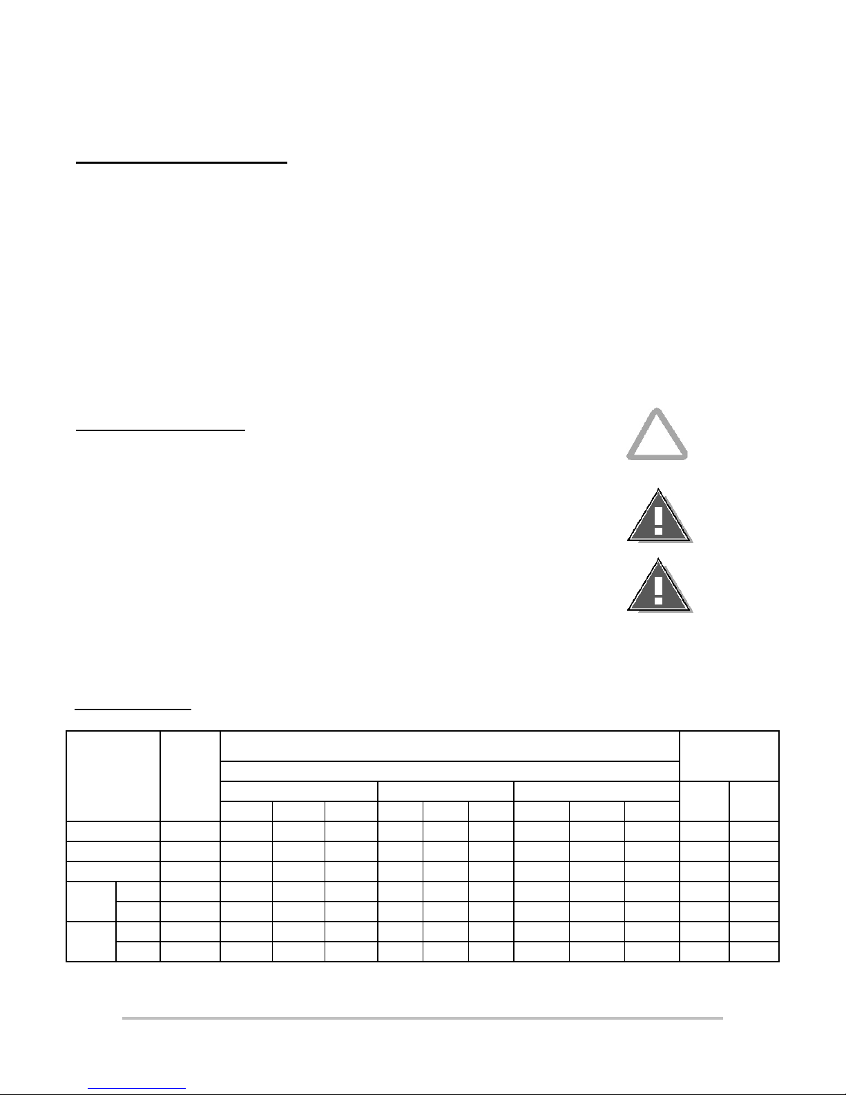
Technical Data
MODEL
NUMBER
24" 12.0 50.0 28.8 28.8 43.3 25.0 25.0 21.7 12.5 12.5 57.7 50.0
36” 18.0 50.0 50.0 50.0 43.3 43.3 43.3 21.7 21.7 21.7 86.5 75.0
48" 24.0 75.0 75.0 50.0 65.0 65.0 43.3 32.5 32.5 21.7 115.5 100.0
60"
72”
TOTAL
K.W.
#1 12.0 50.0 28.8 28.8 43.3 25.0 25.0 21.7 12.5 12.5 57.7 50.0
#2 12.0 50.0 28.8 28.8 43.3 25.0 25.0 21.7 12.5 12.5 57.7 50.0
#1 18.0 50.0 50.0 50.0 43.3 43.3 43.3 21.7 21.7 21.7 86.5 75.0
#2 18.0 50.0 50.0 50.0 43.3 43.3 43.3 21.7 21.7 21.7 86.5 75.0
208 Volt 240 Volt 480 Volt
L1 L2 L3 L1 L2 L3 L1 L2 L3
NOMINAL AMPS PER LINE
THREE PHASE
9
SINGLE
PHASE
208V 240V
Page 10
INSTALLATION CONT’D
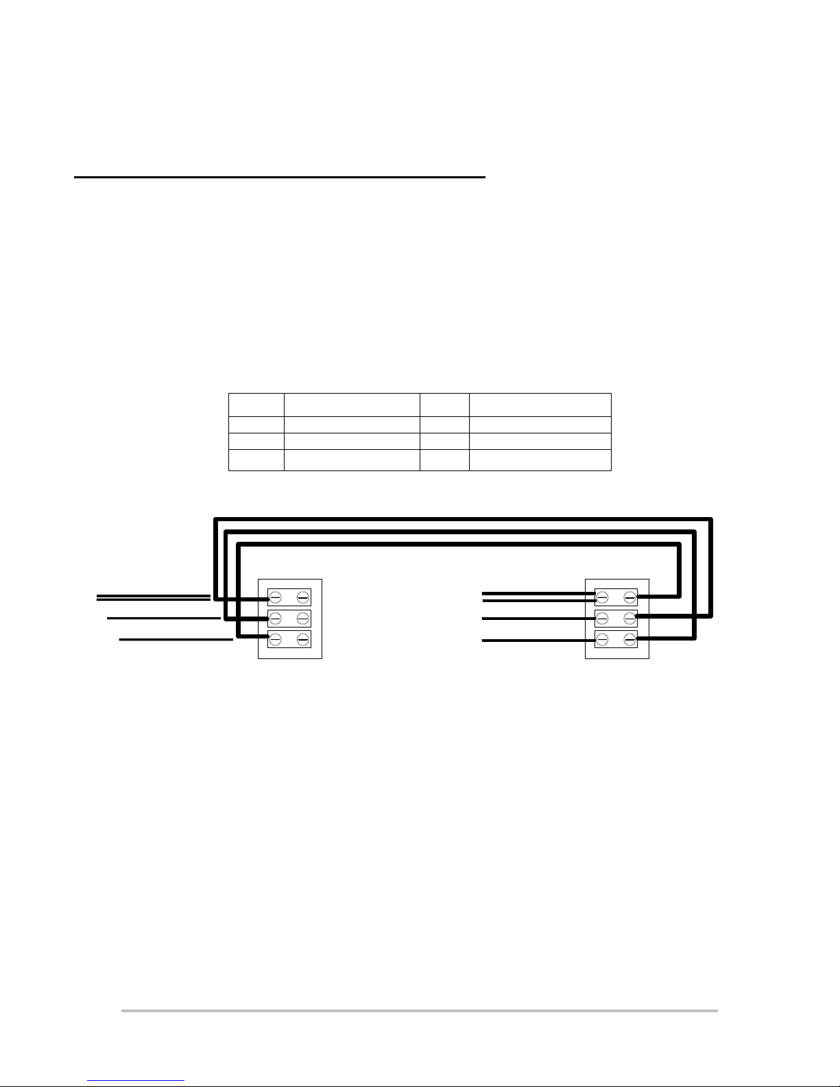
Converting Double Connection to Single Connection
Remove the two rear access panels from the griddle
Remove the wires from the envelope labeled “Single connection jumpers”
Determine which end of the griddle the main power supply connection will enter.
Call this end terminal block 1
Insert the main power supply wires into the open side of this terminal block.
Insert one each of the three wires provided into the side of terminal block 1 which contain the wires that come
from the griddle
Pull the other end of the wires over to the terminal block located at the other power connection.
Insert the wires into the open side of the terminal block as indicated below.
Ensure that all the terminal block screws are securely tightened
From Terminal Block 1 To Terminal Block 2
L1 To L2
L2 To L3
L3 To L1
3 EA. # 8 WIRES PROVIDED IN KIT
WIRES TO GRIDDLE
L1
L2
L3
TERMINAL BLOCK 1
WIRES TO GRIDDLE
L1
L2
L3
TERMINAL BLOCK 2
10
Page 11

INITIAL START UP
Pre-Power On
Before starting the griddle for the first time, clean the griddle body and cooking
surface.
Use a mild soap and water solution, then rinse with clear water and dry.
Power On
Set the main power switch, located at the far left of the control panel, to the "ON"
(up) position (there are two "ON" switches on 5 and 6 foot griddles).
Set each cooking section's power switch, located next to each temperature dial, to
the "ON" (up) position.
Set the temperature dials to 200°F.
Heat the griddle at 200°F for 2 hours to evaporate any moisture that may be in the
elements.
After 2 hours at 200°F, turn the griddle temperature up to 350°F for ½ hour.
After the griddle reaches 350°F for ½ hour, turn the griddle up another 50°F for
another ½ hour and repeat this until the griddle is at 450°F for ½ hour
The griddle may emit a small amount of smoke as the cooking surface passes the
300°F point. Do not be alarmed as the smoke is caused by oils associated with the
manufacturing process and will stop when the griddle reaches 350°F.
Seasoning Cooking Surface
The cooking surface must be "seasoned" in order to eliminate product sticking
during cooking.
To season, heat the griddle to 250°F.
Once at 250°F, coat the cooking surface with non-salted vegetable oil.
Allow the griddle to stand at 250°F until the cooking surface looks dry then coat it
again.
Heat the griddle to 350°F and repeat the procedure.
NOTICE: During the first few hours of operation you may notice
a small amount of smoke coming off the griddle, and a
faint odor from the smoke. This is normal for a new
griddle and will disappear after the first few hours of
use.
11
Page 12
OPERATION
(F)
General
The suggested time and temperature chart (below) is provided as a guide for the
products listed only.
CAUTION: ALWAYS KEEP THE AREA NEAR THE APPLIANCE FREE
FROM COMBUSTIBLE MATERIALS.
CAUTION: KEEP FLOOR IN FRONT OF EQUIPMENT CLEAN AND
DRY. IF SPILLS OCCUR, CLEAN IMMEDIATELY, TO
AVOID THE DANGER OF SLIPS OR FALLS.
SUGGESTED TIMES AND TEMPERATURES
PRODUCTS
HAMBURGER
2 patties per LB 350 6 to 8
4 patties per LB 350 4 to 6
6 patties per LB 350 3 to 4
STEAKS
1/2 to 3/4 inch thick, cooked medium 375 5 to 7
3/4 to 1 inch thick, cooked medium 375 8 to 10
Lamb Chops 350 6 to 8
Pork Chops 350 6 to 8
Salmon 350 6 to 8
Halibut 325 6 to 8
Snapper 325 6 to 8
Hashbrown Potatoes 375 3 to 4
Bacon 350 3 to 4
Sausage Links or Patties 350 3 to 4
Ham (Pre-cooked) 375 2
Eggs 275 2 to 4
Note: The times and temperatures in this chart are intended as a general guide and starting
point. Your actual times and temperatures may vary from this chart.
If different temperature settings are to be used, select one side of the griddle and
operate at the lowest temperature. Adjoining sections should be set at progressively
higher temperatures. Do not try to operate the end sections hot and the center sections
cool.
TEMPERATURE
350
TIME (MIN)
12
Page 13

OPERATION CONT’D
Operations
An understanding of how the griddle sections are controlled will be a valuable aid in loading
your griddle.
Each 12-inch section of your griddle is independently controlled by a temperature controller.
The temperature control sensor is mounted in the center of each cooking section under the
griddle plate.
If the product is loaded directly over the temperature sensor, that section will turn on and the
burner will heat the entire cooking section. If the product is loaded to the side, front or back of
the temperature sensor, the thermostat will react to the temperature change much slower.
During slow periods with minimal loads, do not load directly over the thermostat sensors as
this will unnecessarily turn the burners on and overheat the remainder of the section not being
utilized.
Turn the product and continue cooking until it has reached its desired degree of doneness.
Remove the product from the griddle.
When reloading the griddle, first use the griddle surface on which a previous load was not
placed. This will help insure the proper griddle temperature.
13
Page 14

MAINTENANCE & CLEANING
WARNING: KEEP WATER AND SOLUTIONS OUT OF CONTROLS.
NEVER SPRAY OR HOSE CONTROL CONSOLE.
CAUTION: MOST CLEANERS ARE HARMFUL TO THE SKIN,
EYES, MUCOUS MEMBRANES AND CLOTHING.
PRECAUTIONS SHOULD BE TAKEN TO WEAR
RUBBER GLOVES, GOGGLES OR FACE SHIELD AND
PROTECTIVE CLOTHING. CAREFULLY READ THE
WARNING AND FOLLOW THE DIRECTIONS ON THE
LABEL OF THE CLEANER TO BE USED.
NOTICE: Never leave a chlorine sanitizer in contact with
stainless steel surfaces longer than 10 minutes.
Longer contact can cause corrosion.
Cleaning
• Always start with a cold griddle.
• The stainless exterior can easily be cleaned using a good non-abrasive cleaner.
• Always follow the cleaner manufacturer's instructions when using any cleaner.
• Always apply these cleaners when the griddle is cold and rub in the direction of the
metal's grain.
• At least once a day, remove the waste drawer and wash in the same way as an
ordinary cooking utensil. The drawers are removed by pulling forward until they
are released from their track.
Griddle Surface Care (non-chromium surfaces)
It takes very little time and effort to keep the griddle attractive and performing at top
efficiency. If grease is permitted to accumulate, it will form a gummy cake and then
carbonize into a hard substance which is extremely difficult to remove. To prevent this
condition, the following suggestions for cleanliness should be followed:
• After each use, scrape the griddle with a scraper or flexible spatula to remove
excess grease and food. A waste drawer is provided for the scrapings. If there is an
accumulation of burned on grease and food, the griddle should be thoroughly
scoured and reseasoned. Use pumice or griddle stone while the griddle is warm.
Do not use steel wool because of the danger of steel slivers getting into the food.
14
Page 15

TROUBLESHOOTING
Symptoms
What follows is a chart of Symptoms and Possible Causes to aid in diagnosing
faults with the griddle.
Refer to the Symptoms column to locate the type of failure then to the Possible
Cause for the items to be checked.
To test for a possible causes refer to the TEST section and locate the Possible
Cause then refer to test to identify test procedures.
SYMPTOM POSSIBLE CAUSE
Whole Griddle will not heat
One Section will not heat
Product Burning
Product Under cooked
• No Power to Griddle
• Failed Power switch
• Failed Transformer.
• Failed Power switch (for that section)
• Failed Probe
• Failed Circuit board
• Failed 12-position switch
• Failed contactor
• Failed Element.
• Product left on griddle too long
• Failed Probe
• Failed Circuit board
• Failed 12-position switch
• Product removed too soon
• Failed Probe
• Failed Circuit board
• Failed 12-position switch
15
Page 16
TROUBLESHOOTING CONT’D
TESTS
NOTICE: Service on this, or any other, LANG appliance must be
performed by qualified personnel only. Consult your
authorized service station directory or call the factory
at 1-800-807-9054, or WWW.STAR-MFG.COM
For the service agent nearest you.
WARNING: BOTH HIGH AND LOW VOLTAGES ARE PRESENT
INSIDE THIS APPLIANCE WHEN THE UNIT IS
PLUGGED/WIRED INTO A LIVE RECEPTACLE.
BEFORE REPLACING ANY PARTS, DISCONNECT THE
UNIT FROM THE ELECTRIC POWER SUPPLY.
If an item on the list is followed by an asterisk (*), the work should be done by a
factory authorized service representative.
Possible Cause TEST
Product is cooked too long
Failed Probe
Failed Circuit board
Failed Transformer
Failed Contactor
Failed Element
• No test available, operational condition
• Check probe for proper resistance*
• Confirm that Circuit board is getting correct
voltage and putting out correct voltage*
• Check both Primary and Secondary coils for
correct voltage*
• Remove the wires from the contactor coil and
check for continuity across the contactor coil
connection*
• Ensure the contactor moveable points move
freely up and down*
• Confirm that Elements are getting correct
voltage and have continuity*
CAUTION: USE OF ANY REPLACEMENT PARTS OTHER THAN
THOSE SUPPLIED BY LANG OR THEIR AUTHORIZED
DISTRIBUTORS CAN CAUSE BODILY INJURY TO THE
OPERATOR AND DAMAGE TO THE EQUIPMENT AND
WILL VOID ALL WARRANTIES.
16
Page 17
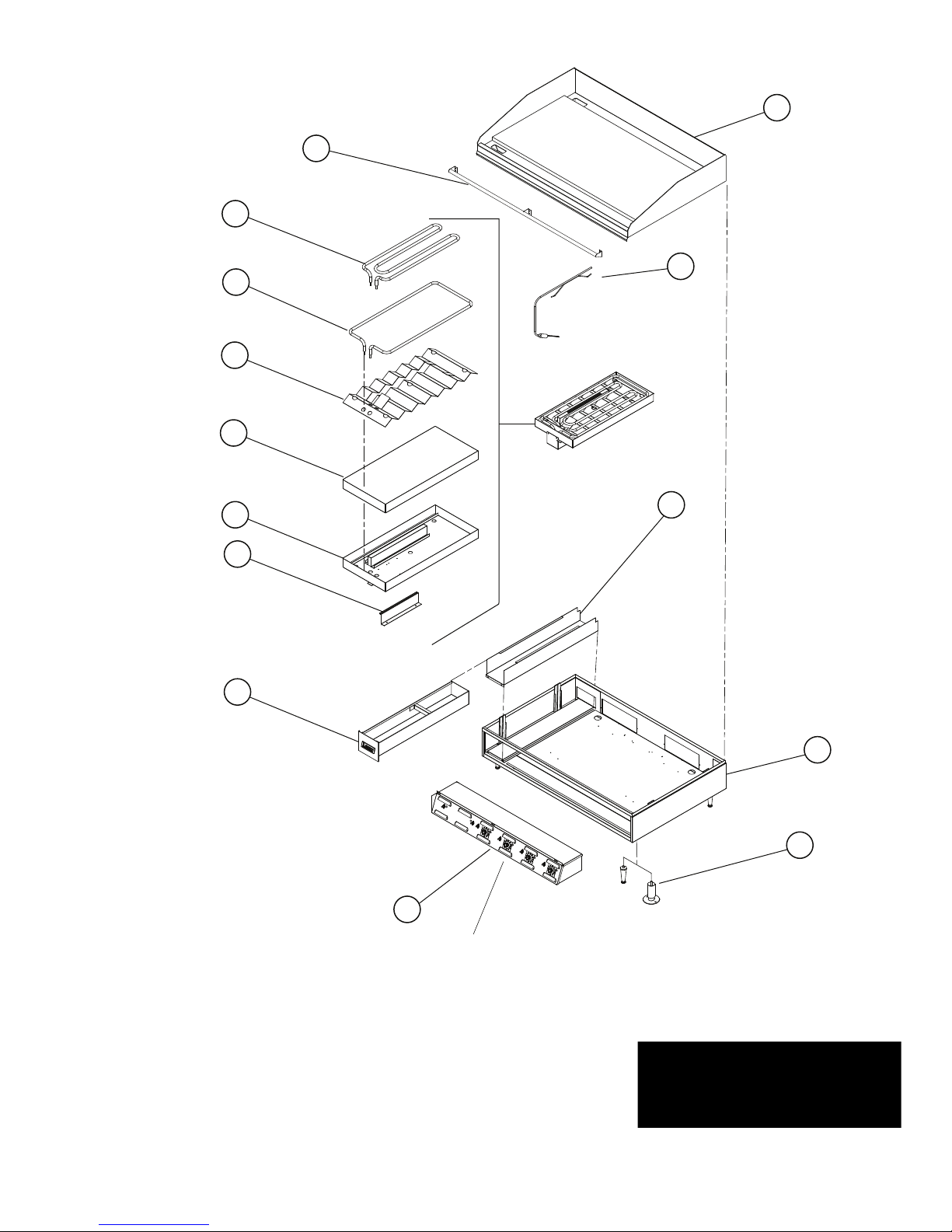
SK2263 Rev. A 9/09/08
Model:
124S - 172S Selectronic Control Electric Griddle
LG Electric Griddle Accu-Temp Control
1
4
5
6
3
2
7
8
9
10
11
12
13
14
For individual parts
SEE DETAIL
A
This drawing contains information confidential
to Star Manufacturing International, Inc.
No reproduction or disclosure of it's
CERTAIN INSTANCES MAY NOT BE AVAILABLE
ILLUSTRATIVE PURPOSES AND IN
SOME ITEMS ARE INCLUDED FOR
contents is permitted.
1
Page 18
PARTS LIST November 20, 2009
Model No: 136SB-WB & 148SB-WB
Selectronic Electric Griddle
FIG NO PART NO. QTY DESCRIPTION APPLICATION
1 K9-XL-722-28 1 PLATE ASY 3’ LGR .5RTD 136SB-WB
2 2E-41100-17 3 TEMP PROBE SEL LG GRIDDLE 136SB-WB
3 K9-XL-228-1 1 BUCKET SLIDE ASSY LGR 136SB-WB
4 K9-XL-220-3 1 BODY ASSEMBLY 3’ LGR 136SB-WB
5 LEGS & FEET NOT INCLUDED
6 K9-LGPS3-C 1 PANEL XL-LG SEL 3’ 208/240V 136SB-WB
7 K9-XL-235-2 1 GREASE BUCKET ASSY LGR S/S 136SB-WB
8 K9-XL-441 3 PROBE HOLDER SELECTRONIC 136SB-WB
9 K9-XL-434 3 ELEMENT PAN ASSEMLBY 136SB-WB
10 2H-XL-424 3 ELEMENT PAN INSULATION 136SB-WB
11 K9-XL-439 3 ELEMENT PAN Z ASSEMBLY 136SB-WB
12 2N-11030-30 3 ELMNT GRID 208V 1257W 136SB-WB
13 2N-11030-29 3 ELE GRD 208/240V4.5KW/6KW 136SB-WB
NI 2E-30501-05 1 TRM STRP 6 POLE W/2PUSH
136SB-WB
FIG NO PART NO. QTY DESCRIPTION APPLICATION
1 K9-XL-722-271 1 PLATE ASY 4’ LGR .5RTD 148SB-WB
2 2E-41100-17 4 TEMP PROBE SEL LG GRIDDLE 148SB-WB
3 K9-XL-228-1 1 BUCKET SLIDE ASSY LGR 148SB-WB
4 K9-XL-220-4 1 BODY ASSEMBLY 4’ LGR 148SB-WB
5 LEGS & FEET NOT INCLUDED
6 K9-LGPS2-C-1 2 PANEL XL-LG SEL 2’ 208/240V 148SB-WB
7 K9-XL-235-2 1 GREASE BUCKET ASSY LGR S/S 148SB-WB
8 K9-XL-441 4 PROBE HOLDER SELECTRONIC 148SB-WB
9 K9-XL-434 4 ELEMENT PAN ASSEMLBY 148SB-WB
10 2H-XL-424 4 ELEMENT PAN INSULATION 148SB-WB
11 K9-XL-439 4 ELEMENT PAN Z ASSEMBLY 148SB-WB
12 2N-11030-30 4 ELMNT GRID 208V 1257W 148SB-WB
13 2N-11030-29 4 ELE GRD 208/240V4.5KW/6KW 148SB-WB
NI 2E-30500-03 2 TRM STRP 6 POLE 30A 300V 148SB-WB
NI 2E-30501-05 1 TRM STRP 6 POLE W/2PUSH
148SB-WB
1
IMPORTANT: WHEN ORDERING, SPECIFY VOLTAGE OR TYPE GAS DESIRED PAGE
1
INCLUDE MODEL AND SERIAL NUMBER OF
Some items are included for illustrative purposes only and in certain instances may not be available.
2
Page 19
PARTS LIST November 20, 2009
Model No: 160SB-WB & 172SB-WB
Selectronic Electric Griddle
FIG NO PART NO. QTY DESCRIPTION APPLICATION
1 K9-XL-722-251 1 PLATE ASY 5’ LGR .5RTD 160SB-WB
2 2E-41100-17 5 TEMP PROBE SEL LG GRIDDLE 160SB-WB
3 K9-XL-228-1 2 BUCKET SLIDE ASSY LGR 160SB-WB
K9-XL-220-3
4
K9-XL-220-2 BODY ASSEMBLY 2’ LGR
5 LEGS & FEET NOT INCLUDED
K9-LGPS3-C
6
K9-LGPS2-C PANEL XL-LG SEL 2’ 208/240V
7 K9-XL-235-2 2 GREASE BUCKET ASSY LGR S/S 160SB-WB
8 K9-XL-441 5 PROBE HOLDER SELECTRONIC 160SB-WB
9 K9-XL-434 5 ELEMENT PAN ASSEMLBY 160SB-WB
10 2H-XL-424 5 ELEMENT PAN INSULATION 160SB-WB
11 K9-XL-439 5 ELEMENT PAN Z ASSEMBLY 160SB-WB
12 2N-11030-30 5 ELMNT GRID 208V 1257W 160SB-WB
13 2N-11030-29 5 ELE GRD 208/240V4.5KW/6KW 160SB-WB
NI 2E-30500-03 2 TRM STRP 6 POLE 30A 300V 160SB-WB
NI 2E-30501-05 1 TRM STRP 6 POLE W/2PUSH 160SB-WB
BODY ASSEMBLY 3’ LGR
1
PANEL XL-LG SEL 3’ 208/240V
1
160SB-WB
160SB-WB
FIG NO PART NO. QTY DESCRIPTION APPLICATION
1 K9-XL-722-261 1 PLATE ASY 6’ LGR .5RTD 172SB-WB
2 2E-41100-17 6 TEMP PROBE SEL LG GRIDDLE 172SB-WB
3 K9-XL-228-1 2 BUCKET SLIDE ASSY LGR 172SB-WB
4 K9-XL-220-3 2 BODY ASSEMBLY 3’ LGR 172SB-WB
5 LEGS & FEET NOT INCLUDED
6 K9-LGPS3-C 2 PANEL XL-LG SEL 3’ 208/240V 172SB-WB
7 K9-XL-235-2 2 GREASE BUCKET ASSY LGR S/S 172SB-WB
8 K9-XL-441 6 PROBE HOLDER SELECTRONIC 172SB-WB
9 K9-XL-434 6 ELEMENT PAN ASSEMLBY 172SB-WB
10 2H-XL-424 6 ELEMENT PAN INSULATION 172SB-WB
11 K9-XL-439 6 ELEMENT PAN Z ASSEMBLY 172SB-WB
12 2N-11030-30 6 ELMNT GRID 208V 1257W 172SB-WB
13 2N-11030-29 6 ELE GRD 208/240V4.5KW/6KW 172SB-WB
NI 2E-30500-03 2 TRM STRP 6 POLE 30A 300V 172SB-WB
NI 2E-30500-07 2 TRM BLOCK 3PLELRGE 125AMP 172SB-WB
NI 2E-30501-05 2 TRM STRP 6 POLE W/2PUSH 172SB-WB
1
IMPORTANT: WHEN ORDERING, SPECIFY VOLTAGE OR TYPE GAS DESIRED PAGE
1
INCLUDE MODEL AND SERIAL NUMBER OF
Some items are included for illustrative purposes only and in certain instances may not be available.
3
Page 20
1
2
3
8
5
10
11
2
12
1
13
14
15
16
16
20
9
7
6
18
19
17
2
4
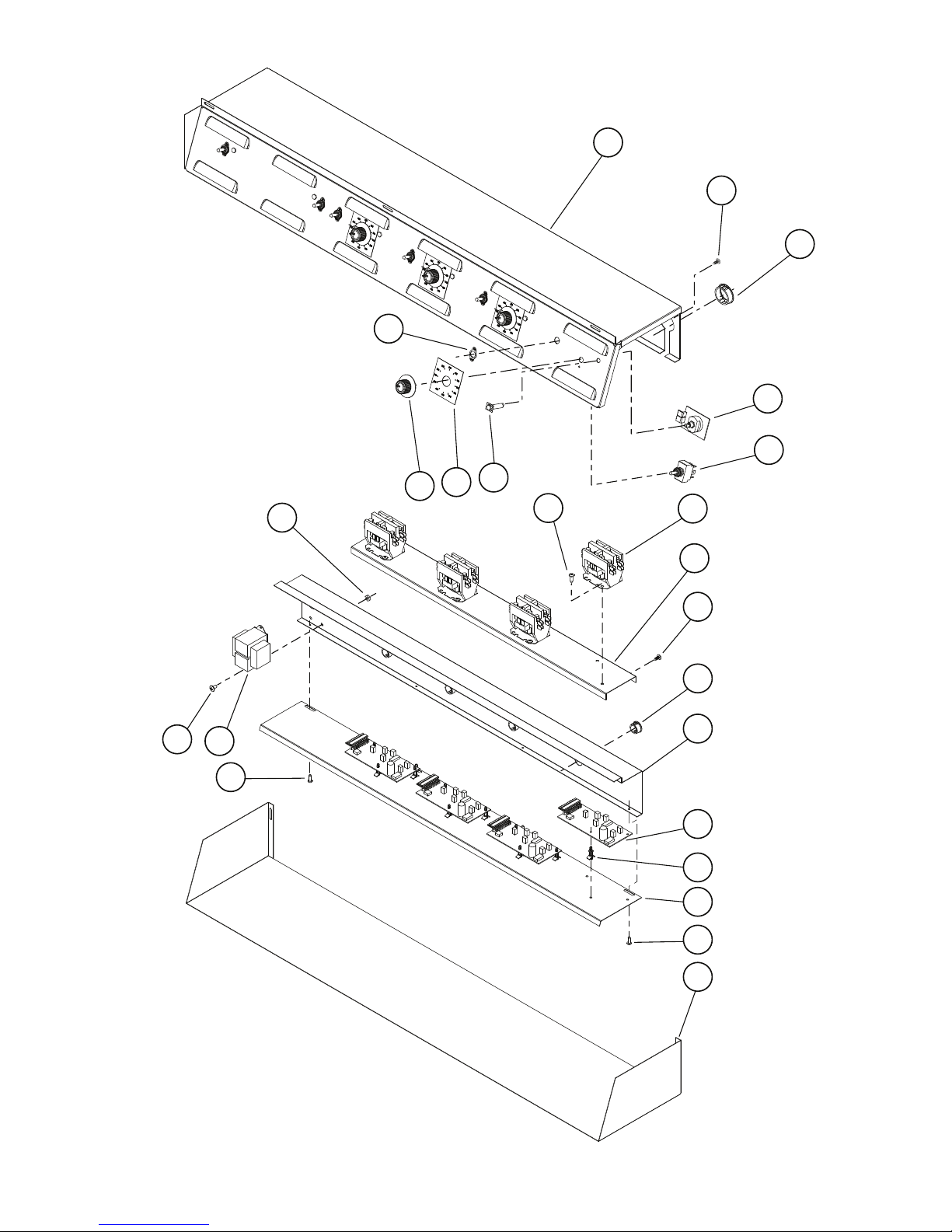
Control Panel Assembly (LPGS4-C shown)
SK2307 Rev. B 7/7/08
DETAIL
A
4
Page 21
PARTS LIST November 12, 2009
Model No: 136SB-WB, 148SB-WB, 160SB-WB & 172SB-WB
Control Panel Assembly
Model Qty Panel Description Panel Part Number
124S 1 PNEL XL-LG SEL 2’ 208/240V K9-LGPS2-C
124S-480V 1 PNEL XL-LG SEL 2’ 480V K9-LGPS2-U
124SHE 1 PNEL SEL 2’ 208/240V W/CSE K9-LGPS2-C-W1
136S 1 PANEL XL-LG SEL 3’ 208/240V K9-LGPS3-C
136S-380VM 1 PANEL CL-LG SEL 3’ 380V K9-LGPS3-K
136S-480V 1 PANEL XL-LG SEL 3’ 480V K9-LGPS3-U
136SB-WB 1 PANEL XL-LG SEL 3’ 208/240V K9-LGPS3-C
136SHE 1 PNEL SEL 3’208/240V W/CSE K9-LGPS3-C-W1
136S-SC 1 PANEL XL-LG SEL 3’ 208/240V K9-LGPS3-C
148S 1 PANEL XL-LG SEL 4’ 208/240V K9-LGPS4-C
148S-480V 1 PANEL XL-LG SEL 4’ 480V K9-LGPS4-U
148SB-WB 2 PANEL XL-LG SEL 2” 208/240V K9-LGPS2-C-1
148SHE-480V 1 PANEL SL ASSY-LG SEL 4’ K9-LGPS4-U-W1
148SR 2 PNL LG-S 2’ 208/240V WB 4’ BDY K9-LGPS2-CWB-4
148S-SC 1 PANEL XL-LG SEL 4’ 480V K9-LGPS4-U
148S-WB 2 PNL LG-S 2’ 208/240V WB 4’ BDY K9-LGPS2-CWB-4
160S
160S-480V
160SB-WB
160SHE 1 PANEL XL-LG SEL 2’ 208/240V K9-LGPS2-C
160SR 1 PANEL XL-LG SEL 2’ 208/240V WB K9-LGPS2-CWB
160S-SC
160S-WB 1 PANEL XL-LG SEL 2’ 208/240V WB K9-LGPS2-CWB
172S 2 PANEL XL-LG SEL 3’ 208/240V K9-LGPS3-C
172SC 2 PANEL XL-LG SEL 3’ 208/240V K9-LGPS3-C
172S-480V 2 PANEL XL-LG SEL 3’ 480V K9-LGPS3-U
172SB-WB 2 PANEL XL-LG SEL 3’ 208/240V K9-LGPS3-C
Fig No Part Number Qty Description Application
K9-XL-725-03
K9-XL-725-030 ELECT BOX ASY 4’ LG SEL LGPS2-CWB-4
K9-XL-725-032 ELECT BOX ASY 2’ LG SEL LGPS2-CWB
1
K9-XL-725-03-W1 ELE BOX ASSY 2’ SEL W/CSE LGPS2-C-W1
K9-XL-725-07 ELECT BOX ASY 3’ LG SEL LGPS3-C, LGPS3-U, LGPS3-K
K9-XL-725-071 ELECT BOX ASY 3’ SEL W/CSE LGPS3-C-W1
K9-XL-725-11 ELECT BOX ASY 4’ LG SELECT LGPS4-C, LGPS4-U
K9-XL-725-13 ELEC BOX ASSY 4’ SEL LGPS4-U-W1
1 PANEL XL-LG SEL 2’ 208/240V K9-LGPS2-C
1 PANEL XL-LG SEL 3’ 208/240V K9-LGPS3-C
1 PANEL XL-LG SEL 2’ 480V K9-LGPS2-U
1 PANEL XL-LG SEL 3’ 480V K9-LGPS3-U
1 PANEL XL-LG SEL 2’ 208/240V K9-LGPS2-C
1 PANEL XL-LG SEL 3’ 208/240V K9-LGPS3-C
1 PANEL XL-LG SEL 2’ 208/240V K9-LGPS2-C
1 PANEL XL-LG SEL 3’ 208/240V K9-LGPS3-C
ELECT BOX ASY 2’ LG SEL LGPS2-C, LGPS2-U
1
1
IMPORTANT: WHEN ORDERING, SPECIFY VOLTAGE OR TYPE GAS DESIRED PAGE
3
INCLUDE MODEL AND SERIAL NUMBER OF
Some items are included for illustrative purposes only and in certain instances may not be available.
5
Page 22
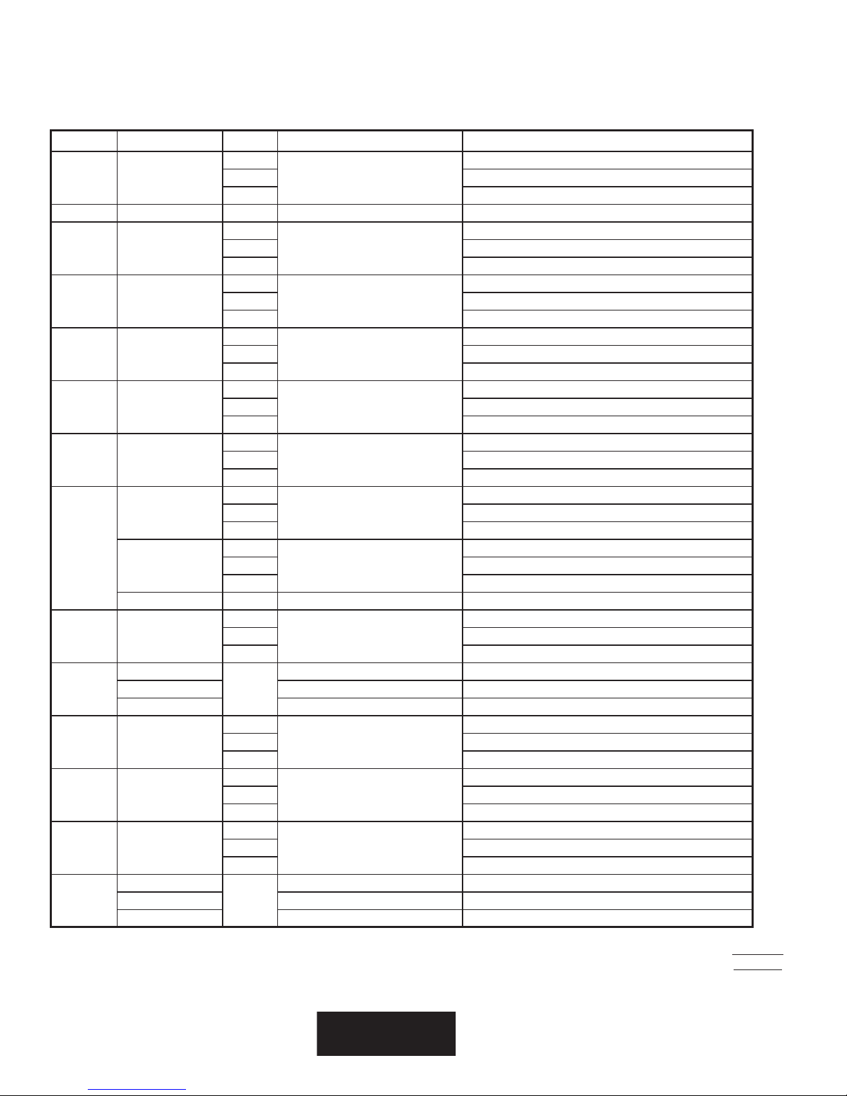
PARTS LIST November 20, 2009
Model No: 136SB-WB, 148SB-WB, 160SB-WB & 172SB-WB
Control Panel Assembly
Fig No Part Number Qty Description Application
14
2 2C-20103-02
3 2K-70801-02 2 SNAP BUSH 1 3/8 SB1375-16 LGPS4-C, LGPS4-U, LGPS3-K
4 2E-30303-05
5 2E-30303-06
6 2R-70701-28
7 2M-60301-29
8 2E-30304-22
2J-31601-01
9
2J-31601-02
2J-31601-07 1 PILOT LT 28V 6 LEAD WHT LGPS2-U, LGPS4-U, LGPS4-U-W1, LGPS3-K
10 2E-30701-04
K9-XL-522-11
11
12 2K-70801-04
13 2E-40101-W19
14 2K-70801-07
15
K9-XL-522-12 CNTR MT PLT 3’ SLCTRNC LG LGPS3-C, LGPS3-U, LGPS3-K
K9-XL-522-13 CONT. MNT PLT 4’ SELEC LG LGPS4-C, LGPS4-U
K9-XL-522-10
K9-XL-522-8 CIRCUIT BOARD MOUNT LGPS2-C, LGPS2-U
K9-XL-522-9 CIRC BOARD MOUNT 3’ LGPS3-C, LGPS3-U
SCRW SM PLT 10 X .5 PHLSL
22 LGPS3-C, LGPS3-U, LGPS3-C-W1, LGPS3-K
26 LGPS4-C, LGPS4-U, LGPS4-U-W1
3
SWT PLATE ON/OFF
4 LGPS3-C, LGPS3-U, LGPS3-C-W1, LGPS3-K
5 LGPS4-C, LGPS4-U, LGPS4-U-W1
3
SWT TOG ON-ON DPDT BLK
4 LGPS3-C, LGPS3-U, LGPS3-K
5 LGPS4-C, LGPS4-U, LGPS4-U-W1
2
KNB BLK 1/4BUSH2SETSCW@90
3 LGPS3-C, LGPS3-U, LGPS3-K
4 LGPS4-C, LGPS4-U
2
PNLLBL SELCT SWTDIAL 450o
3 LGPS3-C, LGPS3-U
4 LGPS4-C, LGPS4-U
2
SWTCB175-450oFW/41100-13
3 LGPS3-C, LGPS3-U, LGPS3-K
4 LGPS4-C, LGPS4-U, LGPS4-U-W1
3
PILOT LT 250V 6LEAD BLK
4 LGPS3-C, LGPS3-U
5 LGPS4-C
2
PILOT LT 480V 6LEAD BLK
3 LGPS3-U, LGPS3-K
4 LGPS4-U, LGPS4-U-W1
2
CONTC 2POLE 30A 24VAC
3 LGPS3-C, LGPS3-U, LGPS3-K
4 LGPS4-C, LGPS4-U, LGPS4-U-W1
CPMTACT. MNT PLT 2’ SEL LGPS2-C, LGPS2-U
1
4
SNAP BUSH 3/4 SB750-10
5 LGPS3-C, LGPS3-U, LGPS3-K
6 LGPS4-C, LGPS4-U
2
CIRBD SI TEMP CNTRL NO
3 LGPS3-C, LGPS3-U, LGPS3-K
4 LGPS4-C, LGPS4-U, LGPS4-U-W1
6
SPACER SUPPORT 1/2LG
9 LGPS3-C, LGPS3-U, LGPS3-K
12 LGPS4-C, LGPS4-U
CIRC BRD MNT 4’ LGPS4-C, LGPS4-U
1
LGPS2-C, LGPS2-U
LGPS2-C, LGPS2-U
LGPS2-C, LGPS2-U
LGPS2-C, LGPS2-U
LGPS2-C, LGPS2-U
LGPS2-C, LGPS2-U
LGPS2-C
LGPS2-U
LGPS2-C, LGPS2-U
LGPS2-U
LGPS2-C, LGPS2-U
LGPS3-C, LGPS2-U
2
IMPORTANT: WHEN ORDERING, SPECIFY VOLTAGE OR TYPE GAS DESIRED PAGE
3
INCLUDE MODEL AND SERIAL NUMBER OF
Some items are included for illustrative purposes only and in certain instances may not be available.
6
Page 23
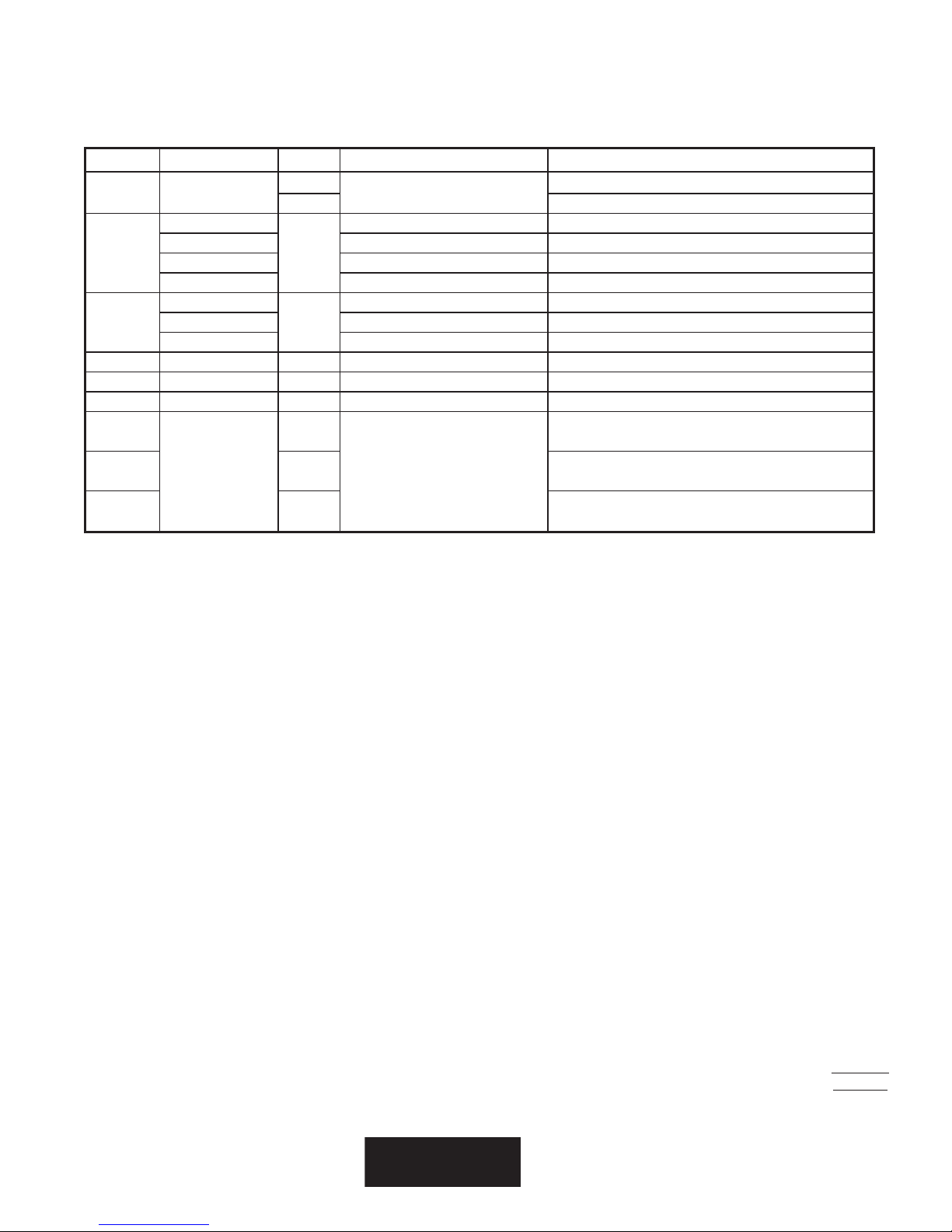
PARTS LIST November 20, 2009
Model No: 136SB-WB, 148SB-WB, 160SB-WB & 172SB-WB
Control Panel Assembly
Fig No Part Number Qty Description Application
16 2C-20102-04
K9-XL-502-31
17
18
19 2C-20101-24 2 SCRW MS PLT 10-32 X .375 ALL
20 2C-20301-15 2 NUT HEX 10-32 PLTD ALL
NI 2E-30501-05 1 TRM STRP 6 POLE W/2PUSH LGPS3-K
NI
NI 3 LGPS3-C, LGPS3-C-W1, LGPS3-CWB, LGPS3-U, LGPS3-K
NI 4 LGPS4-C, LGPSA-C-W1, LGPS4-U, LGPS4-U-W1
K9-XL-524-3 ELECT BOX CVER SPT 3’ SEL LGPS3-C, LGPS3-U, LGPS3-K
K9-XL-524-4 ELECT BOX CVER SPT 4’ SEL LGPS4-C, LGPS4-U
K9-XL-524-5 ELECT BOX CVER SPT 2’ SEL LGPS2-C, LGPS2-U
2E-31400-07
2E-31400-15 XFRMR 480/24VAC LGPS2-U, LGPS3-U, LGPS4-U
2E-31400-18 XFORMR 380/24VAC 40VA U/L LGPS3-K
2T-30401-32
3
SCRW PHD ST 8-32X.5 PLTD
4 LGPS4-C, LGPS4-U, LGPS4-U-W1
ELECT BOX CVER 4’ SEL LGPS4-U-W1
1
XFORMR120-208-240/24V40VA LGPS2-C, LGPS3-C, LGPS4-C
1
2
STAT FXD 400°F DEG OPEN
LGPS2-C, LGPS2-U, LGPS3-C, LGPS3-C-W1, LGPS3-U
LGPS2-C, LGPS2-C-1, LGPS2-C-W1, LGPS2-CWB, LGPS2CWB-4, LGPS2-U
3
IMPORTANT: WHEN ORDERING, SPECIFY VOLTAGE OR TYPE GAS DESIRED PAGE
3
INCLUDE MODEL AND SERIAL NUMBER OF
Some items are included for illustrative purposes only and in certain instances may not be available.
7
Page 24
D
1
C
03
2323
2
8
1313
B
9
A
A
1
:VER
FO
qs
ni
1
TEEHS
94W-41116-M2
1
KNALB
:AERA
2
9
52
4
11
1
21
3
42GL
4
1
2121
01
52
4
5131
01
41
6161
03
124356
6262
3
11
8
1
2
3
4
5
6
7
6
8
9
01
77
1
2
HCTIWS
3
NOITISOP
4
21
5
: ELIF DAC
X
: ETAD .KHC
: .SMID
KNALB
2
3
CINORTCELES CAV042-802 ELDDIRG GNAL
5
: YB .KHC
11
7272
3
2
3
4
5
6
7
6
8
9
01
1
2
HCTIWS
3
NOITISOP
4
21
5
1L2L3L
20/52/01
456
: ETAD .VER
63GL
71
:ON .GWD
52
5
91
1
0202
01
8282
4
81
3
11
88
6
1
2
3
4
5
6
7
6
8
9
01
noitces 2/1 swohs margaid gniriw sihT .3
06-GL a rof snoitces erom owt ddA .2
84-GL a rof noitces erom eno ddA .1
7
1
2
HCTIWS
3
NOITISOP
4
21
5
ESAHP ELGNISESAHP EERHT
SNOITCENNOC ECIVRES
remrofsnart eno ot srotcatnoc 4 naht erom oN .4
SNOITCENNOC YLPPUS REWOP OWT EVAH 27GL & 06GL :ETON
8,6,4,27,5,3,16,3
4,23,13
6,35,3,16,4,2
3L1L
8,5,27,4,1
2L
2
4,15,2
4,1
1L2L
: YB .VER
LAIRETAM
: EPYT
70/52/7
: ETAD .NWD
:NOITPIRCSED
SJD
: # TRAP
: YB .NWD
LAIRETAM
DEIFICEPS ESIWREHTO SSELNU
.SEHCNI NI ERA SNOISNEMID
SELGNA SLAMICED
:ERA SECNARELOT
7
REPMUJREPMUJ
V042V802
PUKOOH TNEMELE
8
LLATSNIEVOMER
44
D
7
ledom 27-GL a rof
2 SSALC ,REMROFSNART 9
DRAOB LORTNOC .PMET 6
PMAL TOLIP ELDDIRG 2
STNEMELE ELDDIRG 1
C
HCTIWS NOITISOP 21 7
KCOLB LANIMRET 5
ROTCATNOC 3
REPMUJ 4
TATS PMETREVO 11
HCTIWS ELGGOT 8
EBORP 01
:etoN
B
63GL ESU 1 # NNOC :06GL
63GL ESU 1 # NNOC :27GL
63GL ESU 2 # NNOC
42GL ESU 2 # NNOC
A
= X. 50. 5.
= XX. 30.
= XXX.510.
gnirutcafunaM
ynapmoC
8
 Loading...