

Page 1

Installation, Operation, and
Maintenance
Instructions
Electric Marine Fryer
Model: 130F-208VM
130F-240VM
130F-440VM
130F-480VM
Star Manufacturing International 10 Sunnen Drive St. Louis, MO.63143-3800
Part Number: 2M-W479 Ph: 314-781-2777 Fax: 314-781-2714
Rev.A
WWW.STAR-MFG.COM May 15, 2007
Page 2
THE INFORMATION IN THIS MANUAL IS CRUCIAL AND MUST BE
RETAINED FOR FUTURE REFERENCE. READ, UNDERSTAND
AND FOLLOW THE INSTRUCTIONS AND WARNINGS CONTAINED
IN THIS MANUAL.
DANGER
WARNING
CAUTION
NOTICE
POTENTIALLY HAZARDOUS SITUATION, WHICH, IF NOT
AVOIDED, COULD RESULT IN DEATH.
POTENTIALLY HAZARDOUS SITUATION, WHICH, IF NOT
AVOIDED, COULD RESULT IN DEATH OR SERIOUS INJURY.
POTENTIALLY HAZARDOUS SITUATION WHICH, IF NOT
AVOIDED, MAY RESULT IN MINOR OR MODERATE INJURY.
Helpful operation and installation instructions and tips are
present.
FOR YOUR SAFETY
DO NOT STORE OR USE GASOLINE OR OTHER FLAMMABLE VAPORS
AND LIQUIDS NEAR THIS OR ANY OTHER APPLIANCE.
WARNING: IMPROPER INSTALLATION, ADJUSTMENT, ALTERATION,
SERVICE OR MAINTENANCE CAN CAUSE PROPERTY DAMAGE, INJURY
OR DEATH. READ THE INSTALLATION, OPERATING AND MAINTENANCE
INSTRUCTIONS THOROUGHLY BEFORE INSTALLING OR SERVICING THIS
EQUIPMENT.
Model #: Purchased from:
Serial #: Location:
Date purchased: Date installed:
Purchase order #: For service, call:
WARNING
THIS EQUIPMENT IS APPROVED FOR INSTALLATION ONLY ON
VESSELS GREATER THAN 65 FEET IN LENGTH, IN
ACCORDANCE WITH USCG REGULATIONS IN TITLE 46 CFR
110-113
Page 3

TABLE OF CONTENTS
CHAPTER PAGE
1. Table Of Contents...................................................................................3
2. List Of Illustrations ..................................................................................4
3. Read First ...............................................................................................5
4. Specification Sheet .................................................................................7
5. Leg Specification.....................................................................................9
6. Equipment Description............................................................................11
7. Unpacking...............................................................................................11
8. Installation............................................................................................... 12
9. Operation ................................................................................................13
10. Maintenance & Cleaning .........................................................................15
11. Wiring Diagram .......................................................................................18
3
Page 4

List Of Illustrations
Illustration Page
1. Specification Sheet .................................................................................7
2. Leg Layout ..............................................................................................9
3. Oil Fill Level ............................................................................................13
4. Wiring Diagram ....................................................................................... 18
4
Page 5
CAUTION
CAUTION
CAUTION
DANGER
EACH UNIT IS EXTREMELY HEAVY. FOR SAFE HANDLING, INSTALLER
SHOULD OBTAIN HELP AS NEEDED, OR EMPLOY APPROPRIATE
MATERIALS HANDLING EQUIPMENT (SUCH AS A FORKLIFT, DOLLY, OR
PALLET JACK) TO REMOVE THE UNIT FROM THE SKID AND MOVE IT TO
THE PLACE OF INSTALLATION.
ANY STAND, COUNTER OR OTHER DEVICE ON WHICH THE FRYER WILL
BE LOCATED MUST BE DESIGNED TO SUPPORT THE WEIGHT OF THE
FRYER.
SHIPPING STRAPS ARE UNDER TENSION AND CAN SNAP BACK WHEN
CUT.
THIS APPLIANCE MUST BE GROUNDED AT THE TERMINAL PROVIDED.
FAILURE TO GROUND THE APPLIANCE COULD RESULT IN
ELECTROCUTION AND DEATH.
WARNING
NOTICE
NOTICE
WARNING
CAUTION
WARNING
WARNING
CAUTION
CAUTION
WARNING
INSTALLATION OF THE UNIT MUST BE DONE BY PERSONNEL
QUALIFIED TO WORK WITH ELECTRICITY AND PLUMBING. IMPROPER
INSTALLATION CAN CAUSE INJURY TO PERSONNEL AND/OR DAMAGE
TO EQUIPMENT. UNIT MUST BE INSTALLED IN ACCORDANCE WITH ALL
APPLICABLE CODES.
The data plate is located behind the access door, over the tank drain. The
fryer voltage, wattage, serial number, wire size, and clearance
specifications are on the data plate. This information should be carefully
read and understood before proceeding with the installation.
The installation of any components such as a vent hood, grease
extractors, fire extinguisher systems, must conform to their applicable
National, State and locally recognized installation standards.
MAKE SURE THE MAIN POWER SUPPLY TO THE FRYER IS TURNED OFF
AT THE SOURCE PRIOR TO CONNECTING POWER TO THE FRYER.
BE SURE THE POWER SUPPLY VOLTAGE MATCHES THE VOLTAGE
SPECIFIED ON THE DATA PLATE.
NEVER ENERGIZE THE HEATING ELEMENTS WITH NO OIL IN THE
KETTLE OR WITH THE OIL LEVEL MORE THAN 3-INCHES FROM THE
LOWER FILL LEVEL
ALWAYS TURN THE FRYER POWER SWITCH OFF BEFORE LIFTING THE
HEATING ELEMENTS OUT OF THE FRYER OIL.
ALWAYS KEEP THE AREA NEAR THE APPLIANCE FREE FROM
COMBUSTIBLE MATERIALS.
KEEP FLOOR IN FRONT OF EQUIPMENT CLEAN AND DRY. IF SPILLS
OCCUR, CLEAN IMMEDIATELY, TO AVOID THE DANGER OF SLIPS OR
FALLS.
KEEP WATER AND SOLUTIONS OUT OF CONTROLS. NEVER SPRAY OR
HOSE CONTROL CONSOLE, ELECTRICAL CONNECTIONS, ETC.
5
Page 6

CAUTION
NOTICE
WARNING
CAUTION
MOST CLEANERS ARE HARMFUL TO THE SKIN, EYES, MUCOUS
MEMBRANES AND CLOTHING. PRECAUTIONS SHOULD BE TAKEN TO
WEAR RUBBER GLOVES, GOGGLES OR FACE SHIELD AND PROTECTIVE
CLOTHING. CAREFULLY READ THE WARNING AND FOLLOW THE
DIRECTIONS ON THE LABEL OF THE CLEANER TO BE USED.
Service on this or any other, STAR appliance must be performed by qualified
personnel only. Consult your authorized service agent directory or call the
factory at 1-800-807-9054 or visit our website WWW.STAR-MFG.COM. For the
service agent nearest you.
BOTH HIGH AND LOW VOLTAGES ARE PRESENT INSIDE THIS APPLIANCE
WHEN THE UNIT IS PLUGGED/WIRED INTO A LIVE RECEPTACLE. BEFORE
REPLACING ANY PARTS, DISCONNECT THE UNIT FROM THE ELECTRIC
POWER SUPPLY.
DO NOT THROW ICE INTO THE FRYER BASKET
WHILE THE UNIT IS HOT. FAILURE TO COMPLY
MAY RESULT IN SERIOUS INJURY AND MAY
DAMAGE THE EQUIPMENT.
USE OF ANY REPLACEMENT PARTS OTHER THAN THOSE SUPPLIED BY
Star Manufacturing OR THEIR AUTHORIZED DISTRIBUTORS CAN CAUSE
BODILY INJURY TO THE OPERATOR AND DAMAGE TO THE EQUIPMENT
AND WILL VOID ALL WARRANTIES.
6
Page 7
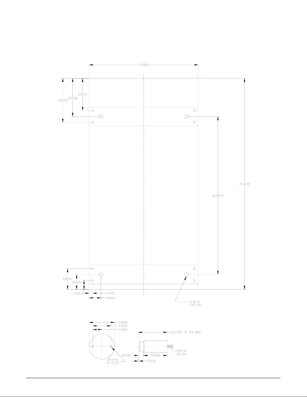
F-28SM & R-28SM
Leg Specification
7
Page 8
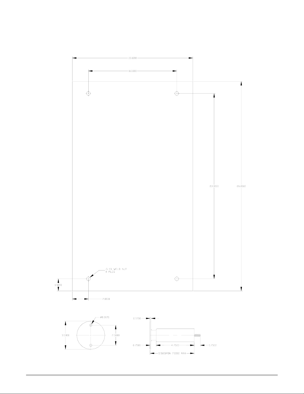
C-28SM
Leg Specification
FRYER BASE
8
Page 9

Equipment Description
Items
¾ 1 ea. C-28M or 1ea. F-28M or 1ea R-28M
¾ 4 ea. 6”, Bolt down legs (F-28M)
¾ 4 ea. 4”, Bolt down legs (C-28M)
¾ 1 ea. Operation Manual
¾ 1 ea. Marine Handle
Fryer Controls
The Fryer comes with a “ON / OFF toggle switch, one mechanical thermostat that has
a temperature range of 200°F -400°F and three indicator lamps for power, heat, and
over temp. In addition to the standard controls, the fryer comes with a power interrupt
terminal block, a shunt trip terminal block and an over temperature test switch.
9
Page 10

CAUTION
CAUTION
CAUTION
EACH IS EXTREMELY HEAVY. FOR SAFE HANDLING, INSTALLER
SHOULD OBTAIN HELP AS NEEDED, OR EMPLOY APPROPRIATE
MATERIALS HANDLING EQUIPMENT (SUCH AS A FORKLIFT, DOLLY, OR
PALLET JACK) TO REMOVE THE UNIT FROM THE SKID AND MOVE IT TO
THE PLACE OF INSTALLATION.
ANY STAND, COUNTER OR OTHER DEVICE ON WHICH THE FRYER WILL
BE LOCATED MUST BE DESIGNED TO SUPPORT THE WEIGHT OF THE
FRYER.
SHIPPING STRAPS ARE UNDER TENSION AND CAN SNAP BACK WHEN
CUT.
Receiving the Fryer
Upon receipt, check for freight damage, both visible and concealed. Visible
damage should be noted on the freight bill at the time of delivery and signed
by the carrier's agent. Concealed loss or damage means loss or damage,
which does not become apparent until the merchandise has been unpacked.
If concealed loss or damage is discovered upon unpacking, make a written
request for inspection by the carrier's agent within 15 days of delivery. All
packing material should be kept for inspection. Do not return damaged
merchandise to Star Manufacturing Company. File your claim with the
carrier.
Location
Prior to un-crating, move the fryer as near its intended location as practical.
The crating will help protect the unit from the physical damage normally
associated with moving it through hallways and doorways.
Un-Crating
The fryer will arrive inside a wood frame covered by a cardboard box and
strapped to a skid. Remove the cardboard cover, cut the straps and
remove the wood frame. The fryer may now be removed from the skid.
Installing the Legs
To install the legs, place some cardboard on the floor and gently tip the
fryer portion onto its side. A threaded weld nut is provided in each of the
four corners of the unit. Thread each leg into the threaded weld nuts and lift
the fryer back onto the legs. (See “Leg Specification”).
Unpacking
10
Page 11

DANGER
Installation
THIS APPLIANCE MUST BE GROUNDED AT THE TERMINAL PROVIDED.
FAILURE TO GROUND THE APPLIANCE COULD RESULT IN
ELECTROCUTION AND DEATH.
WARNING
NOTICE
NOTICE
INSTALLATION OF THE UNIT MUST BE DONE BY PERSONNEL
QUALIFIED TO WORK WITH ELECTRICITY AND PLUMBING. IMPROPER
INSTALLATION CAN CAUSE INJURY TO PERSONNEL AND/OR DAMAGE
TO EQUIPMENT. UNIT MUST BE INSTALLED IN ACCORDANCE WITH ALL
APPLICABLE CODES.
The data plate is located behind the access door, over the tank drain. The
fryer voltage, wattage, serial number, wire size, and clearance
specifications are on the data plate. This information should be carefully
read and understood before proceeding with the installation.
The installation of any components such as a vent hood, grease
extractors, fire extinguisher systems, must conform to their applicable
National, State and locally recognized installation standards.
Electrical Connection
A 1¼” knockout is provided on the unit for electrical connection (see
“Specification Sheet for knockout location & wiring diagram for proper
terminal block connection & phasing).
The electrical connection must be made in accordance with local codes or
in the absence of local codes with National Electrical Code latest edition
(in Canada use: CSA STD. C22.1).
Safety Circuit Connections
Fire Control Shutoff
Two terminals are provided on the four pole terminal block for connection to
an external fire control system if required. A jumper is provided across two
of these terminals when the fryer leaves the factory. The jumper on this
terminal block is in series with the power switch circuit. If connection to a fire
control system is required, remove this jumper and supply a relay contact
closure to maintain this closed circuit. If the fire control system does not
have this type of output, a separate relay must be provided to interface the
system. DO NOT APPLY VOLTAGE TO THIS CONNECTION.
Shunt Trip Circuit
Two terminals are provided on the four pole terminal block for a shunt trip
circuit. Connect to the shunt terminals of the main circuit breaker.
The Fryer can now be connected to power.
CAUTION
BE SURE THE POWER SUPPLY VOLTAGE MATCHES THE VOLTAGE
SPECIFIED ON THE DATAPLATE.
11
Page 12

CAUTION
NEVER ENERGIZE THE HEATING ELEMENTS WITH NO OIL IN THE
KETTLE OR WITH THE OIL LEVEL MORE THAN 3-INCHES FROM THE
LOWER FILL LEVEL
Filling the Fryer
Fill the fryer with cooking oil. There are two fill marks on the sides of the kettle. The oil level
should be maintained between the upper and lower marks. When the elements are out of the
unit the oil should not sink below the bottom fill mark and when the elements are in the oil it
should not rise above the top fill mark.
Operation
Turning the Fryer On
The power switch on the control box at the front of the fryer energizes the control circuits.
When this switch is on, the “power” indicator lamp will be illuminated.
Setting the Temperature
Turn the temperature selector dial on the thermostat to the desired temperature setting. This
control is located above the elements at the rear of the kettle. The “heat” indicator lamp will
illuminate indicating power is applied to the heating elements.
Over-Temperature Indicator
The lamp marked “over temp” will illuminate if the oil reaches an over temperature condition.
The over temperature thermostat shuts off the fryer before the oil reaches a dangerously high
temperature.
CAUTION
ALWAYS TURN THE FRYER POWER SWITCH OFF BEFORE LIFTING THE
HEATING ELEMENTS OUT OF THE FRYER OIL.
Raising the Elements
The elements may be raised and locked in the up position. The latch is located on the rear top
surface of the fryer and may be activated by lifting the handle at either side of the fryer.
12
Page 13

Operation cont’d
Draining the Oil
A drain valve is provided at the left front of the fryer. A lever that is located inside the access
panel is used to open and close the drain valve.
To drain the oil, make sure that the valve is closed and the oil is cool. Remove the steel cap
from the drainpipe. Connect a drainpipe extension to the drainpipe. Move the lever into the
open position and allow draining. Close valve after draining is complete and replace the end
cap.
Controls
Power Switch- A toggle switch used to turn the unit on and off.
Pilot Lights- Lights that are located in the rear control panel area.
Power- Lights up when the power switch is in the “ON” position.
Heat- Lights up when the element contactors engage.
Over-temp- Lights up when the over-temperature thermostat trips.
NOTICE Follow all established safety precautions as described in you
operations manual.
Testing Procedures for the Lang Model 130F Safety System
Important: Heed warnings listed on pages 5 and 6 prior to proceeding with these test
procedures!
The limiting controls test switch, located at the front control panel, is a three-position switch used
to test the first limit thermostats. To test the first limit thermostat push the switch to position “1” and
hold until the audible alarm sounds and the over-temp light comes on (this will happen when the
oil reaches a temperature of approximately 450ºF (232ºC). Next release the switch, if all the power
to the fryer goes off, this indicates that the second over temperature has tripped as well – and has
caused the “shunt trip” circuit breaker to activate. Note the “shunt trip” breaker is not located within
the fryer.
If it is required that the second over temperature thermostat is tested independently (or if the
power remains on the fryer with the switch in its normal, center, position), allow the oil to cool to
approximately 400ºF (204ºC). Restore power to the unit by resetting the shunt trip circuit breaker
(if necessary). Pull the over-temp test switch to position “2” and hold until the “shunt trip” circuit
breaker is activated (this will happen, when the oil reaches a temperature of approximately 450ºF
(232ºC).
Allow the fryer to cool down. Restore power to the unit by resetting the “shunt trip” circuit breaker.
13
Page 14

Maintenance & Cleaning
CAUTION
CAUTION
WARNING
CAUTION
ALWAYS KEEP THE AREA NEAR THE APPLIANCE FREE FROM
COMBUSTIBLE MATERIALS.
KEEP FLOOR IN FRONT OF EQUIPMENT CLEAN AND DRY. IF SPILLS
OCCUR, CLEAN IMMEDIATELY, TO AVOID THE DANGER OF SLIPS OR
FALLS.
KEEP WATER AND SOLUTIONS OUT OF CONTROLS. NEVER SPRAY OR
HOSE CONTROL CONSOLE, ELECTRICAL CONNECTIONS, ETC.
MOST CLEANERS ARE HARMFUL TO THE SKIN, EYES, MUCOUS
MEMBRANES AND CLOTHING. PRECAUTIONS SHOULD BE TAKEN TO
WEAR RUBBER GLOVES, GOGGLES OR FACE SHIELD AND
PROTECTIVE CLOTHING. CAREFULLY READ THE WARNING AND
FOLLOW THE DIRECTIONS ON THE LABEL OF THE CLEANER TO BE
USED.
Fryer Cleaning
Daily Cleaning
It is recommended the fryer oil be kept as clean as possible by straining
regularly (several times a day) and filtering daily. This will lengthen the life of
your oil and improve the performance of the fryer.
Weekly or As Required
1. Turn power switch off.
2. Remove the baskets, let baskets drain and then set aside.
3. Raise heating elements out of oil and lock in up position.
4. Drain Oil (See Draining the oil on previous page).
5. Remove loose food particles from heating units with spatula and wire brush.
6. Flush out scrapings and sediment with a small quantity of hot oil, and allow
draining thoroughly.
7. Close drain valve and fill with a fryer cleaning agent or soapy solution of
non-corrosive grease dissolving cleaner.
8. Set thermostat to 250ºF (121ºC).and boil solution for 15 to 20 minutes.
9. Drain solution from kettle. Refill with water and add 1/2 cup of white vinegar
to neutralize alkaline left by soap. Bring solution to a boil and allow to stand
for a few minutes.
10. Drain kettle and rinse with clear, hot water. Dry kettle and heating units
thoroughly, and close drain valve.
11. Refill fryer with oil, and lower heating elements slowly.
12. Operate fryer as normal.
Emergency Lockout
Locate power disconnect at source and remove power from fryer.
Long Term Storage
Secure fryer from power.
Drain oil from kettle.
Apply a generous amount of Lang Mfg. Prima Shine (72804-41) to the
stainless steel.
14
Page 15

Maintenance & Cleaning cont’d
Temperature Control
A bulb thermostat located near the right heating element as the fryer is viewed from the front provides
temperature control. This thermostat controls the #1 contactor. The control portion of the thermostat is
located in the component box at the back of the fryer.
Over-Temperature Protection
The over-temperature thermostat is located next to the left heating element and provides protection in
case of malfunction of the temperature control. It will open both contactors removing all power from the
heating elements.
Optional Shunt Trip Protection
The shunt trip temperature thermostat located next to the center-heating element provides protection in
case of malfunction of the temperature control. It is used in conjunction with a shunt trip circuit, which will
disconnect power to the fryer at the circuit breaker.
Thermostat Bulbs Check
The three thermostat bulbs, (temperature control thermostat bulb, over-temp thermostat bulb and shunt
trip thermostat bulb), are all connected to the fryer heating elements. The brackets that hold these bulbs
in place should be checked on a regular basis for tightness. If any of the brackets/ bulbs become loose,
the brackets that hold the bulbs should be tightened right away.
Component Access
The temperature control thermostat, over temperature thermostat, and shunt trip thermostat are all
located in the component box at the back of the fryer as well as the indicator lamps. This box may be
removed by removing the 4 sheet metal screws located beneath the box on the left and right sides of the
fryer lower front. All other components are located at the base of the unit in the back or behind the
access panel in the front to the unit.
In the event the fryer is built into a location, all maintenance may be done from the front by removing the
oil pot to gain access to the components. To remove the pot, the control box must be removed as above.
Also, remove the small section of sheet metal baffle held on by 2 sheet metal screws, located just above
the drain valve. The front of the pot may now be lifted up and moved forward until the rear of the pot will
rotate up and out. The baffles behind the pot may be removed by taking out the 4 screws. This exposes
the components.
15
Page 16

Maintenance & Cleaning cont’d
Calibration
The Fryer calibration procedure consists of accessing and adjusting the
temperature thermostat. The temperature control thermostat is located behind
the component box on the top at the back of the fryer.
Calibration Check
¾ Remove the elements from the fryer tank and wrap a temperature-sensing
probe around the capillary tube of the temperature control thermostat.
¾ Place elements back in fryer tank and set thermostat to 350°F.
¾ Allow fryer to reach temperature and cycle for 15 minutes.
¾ After fryer has cycled for 15 minutes, record the on and off temperatures for
three cycles and average these temperatures together (add together and
divide by six), the temperature should be between 340-360°F.
Calibration Adjustment
The average temperature should only be off by 340-360°F (171-182ºC).. If
temperature is off then a 1/16” flat blade screwdriver with a 2” shaft is required
to make adjustments on the thermostat.
¾ Maintain the temperature at 350°F. (177ºC)
¾ Without turning the thermostat, remove the knob.
¾ Locate the adjustment screw at the base of the shaft and insert the
screwdriver.
¾ Grasp the shaft and turn the screw, counter clockwise to increase and
clockwise to decrease, (1/8 of a turn will move the temperature 5-7 °F in
either direction).
¾ Reinstall the oven knob and recheck the oven temperature.
NOTICE
WARNING
CAUTION
Troubleshooting
Service on this, or any other, STAR appliance must be performed by
qualified personnel only. Consult your authorized service agent directory or
call the factory at 1-800-807-9054 or visit our website WWW.STAR-MFG.COM for
the service agent nearest you.
BOTH HIGH AND LOW VOLTAGES ARE PRESENT INSIDE THIS APPLIANCE
WHEN THE UNIT IS PLUGGED/WIRED INTO A LIVE RECEPTACLE. BEFORE
REPLACING ANY PARTS, DISCONNECT THE UNIT FROM THE ELECTRIC
POWER SUPPLY.
USE OF ANY REPLACEMENT PARTS OTHER THAN THOSE SUPPLIED BY
Star Manufacturing OR THEIR AUTHORIZED DISTRIBUTORS CAN CAUSE
BODILY INJURY TO THE OPERATOR AND DAMAGE TO THE EQUIPMENT
AND WILL VOID ALL WARRANTIES.
Not Heating
Probable Cause Corrective Action
Incorrect wiring
Defective transformer
Defective Fuses
Defective Contactor
Defective Thermostat
Defective Element
Confirm that fryer is getting proper voltage.
Confirm that fryer is phased correctly.
Confirm that transformer is getting correct voltage.
Confirm that transformer is putting out correct voltage.
Replace fuses.
Confirm that contactor is getting correct voltage on the coil.
Confirm that thermostat is getting correct voltage.
Confirm that thermostat is operating properly.
Confirm that element is getting correct voltage
Check element for normal operation. (11.5 Amps )
16
Page 17

ELEMENT (208, 220, OR 240 V)
CIRCUIT BREAKER, 2/10 AMP
CONTACTOR, 3 POLE, 240 V COIL
BUZZER, 240 V
EL1
CB
C1 & C2
BZ
TB TERMINAL BLOCK, 3 POLE
LAMP, INDICATOR, HEAT, AMBER
LAMP, INDICATOR, POWER, GREEN
THERMOSTAT, HI-LIMIT, 450 F
THERMOSTAT, HI-LIMIT, 425 F
ELEMENT (208, 220, OR 240 V)
ELEMENT (208, 220, OR 240 V)
IL2
IL1
HL2
HL1
EL3
EL2
THERMOSTAT, REGULATING, 400 F
SWITCH, TOGGLE, HILIMIT BYPASS
SWITCH, TOGGLE, POWER
RELAY, 2 POLE, 240 V COIL
LAMP, INDICATOR, OVERTEMP, RED
TH
SW2
SW1
RE & RE2
IL3
C
ITEM DESCRIPTION
2,5
3,6
1,4
L2
L1
THREEL3PHASE
SERVICE CONNECTIONS
L1 L2 L3
TERMINAL BLOCK
C
CB
SW1-2
EL2
56
EL1
12
EL3
AMPS 3 PHASE
C
43
L1 L2 L3
33.3 33.3 33.3
26.5 26.5 26.5
28.9 28.9 28.9
12
10.2
12.0
TOTAL
2M-61116-20 Rev C
KW
4.0 4.0 4.0
4.0 4.0 4.0
3.4 3.4 3.4
L1-L2 L2-L3 L1-L3
208
220
240
VOLT
LANGSTAR
HL2
C28SM130FM
MODELS:
C28-Marine 208-240VAC
130F- Marine 208-240VAC
MODEL MODEL
C
SW1-1
C1
IL1
Tes t 1
Tes t 2
SW2
RE2
C2
IL2
t°
TH
Tes t 1
SW2
HL1
BZ
IL3
RE
SHUNT-TRIP CIRCUIT BREAKER
PROVIDED BY OTHERS
NO REPRODUCTION OR DISCLOSURE OF ITS CONTENTS IS PERMITTED.
THIS DRAWING CONTAINS INFORMATION CONFIDENTIAL TO STAR MFG. INT'L. INC.
Page 18

ELEMENT (380,415, 440, OR 480 V)
CIRCUIT BREAKER, 2/10 AMP
CONTACTOR, 3 POLE, 240 V COIL
BUZZER, 240 V
ELEMENT (380,415, 440, OR 480 V)
ELEMENT (380,415, 440, OR 480 V)
LAMP, INDICATOR, HEAT, AMBER
LAMP, INDICATOR, POWER, GREEN
THERMOSTAT, HI-LIMIT, 450 F
THERMOSTAT, HI-LIMIT, 425 F
THERMOSTAT, REGULATING, 400 F
SWITCH, TOGGLE, HILIMIT BYPASS
SWITCH, TOGGLE, POWER
RELAY, 2 POLE, 240 V COIL
LAMP, INDICATOR, OVERTEMP, RED
C
10/6/2003
2,5
3,6
1,4
L2
L1
THREEL3PHASE
SERVICE CONNECTIONS
L1 L2 L3
TB
C
TB TERMINAL BLOCK, 3 POLE
BZ
CB
C1 & C2
EL1
EL2
EL3
HL1
HL2
ITEM DESCRIPTION
IL1
EL2
EL1
TR TRANSFORMER
14.0
56
EL3
43
12
15.3
14.0
15.3
AMPS 3 PHASE
L1 L2 L3
14.0
15.3
12.0
TOTAL
TH
SW2
SW1
RE & RE2
IL3
IL2
KW
4.0 4.0 4.0
4.0 4.0 4.0 12.0
L1-L2 L2-L3 L1-L3
415
380
VOLT
13.2
13.2
13.2
12.0
4.0 4.0 4.0
440
12.1
12.1
12.14.0 4.0 4.0 12.0480
2M-61116-21 Rev C
MODELS:
C28-Marine 380-480VAC
130F- Marine 380-480VAC
LANGSTAR
HL2
CB
C28SM130FM
MODEL MODEL
C
SW1-2
240
440/480
C1
TR
SW1-1
IL1
Tes t 1
Test 2
SW2
RE2
C2
IL2
t°
TH
Test 1
SW2
HL1
BZ
IL3
SHUNT-TRIP CIRCUIT BREAKER
RE
PROVIDED BY OTHERS
NO REPRODUCTION OR DISCLOSURE OF ITS CONTENTS IS PERMITTED.
THIS DRAWING CONTAINS INFORMATION CONFIDENTIAL TO STAR MFG. INT'L. INC.
Page 19

THIS DRAWING CONTAINS INFORMATION CONFIDENTIAL TO STAR MFG. INT'L. INC.
NO REPRODUCTION OR DISCLOSURE OF ITS CONTENTS IS PERMITTED.
SHUNT-TRIP CIRCUIT BREAKER
PROVIDED BY OTHERS
RE
TH
IL3
BZ
C
MODEL MODEL
SW1-1
IL1
TR
440/480
240
CB
Test 2
RE2
SW2
Tes t 1
C1
SW1-2
HL1
SW2
Test 1
t°
IL2
C2
130F- Marine 380-480VAC
2M-61116-21 Rev C
C28-Marine 380-480VAC
MODELS:
12.14.0 4.0 4.0 12.0480
12.1
12.1
C28SM130FM
440
4.0 4.0 4.0
12.0
13.2
13.2
13.2
415
4.0 4.0 4.0 12.0
14.0
14.0
14.0
380
4.0 4.0 4.0
12.0
15.3
15.3
15.3
VOLT
L1-L2 L2-L3 L1-L3
TOTAL
L1 L2 L3
LANGSTAR
KW
AMPS 3 PHASE
HL2
12
EL1
43
EL3
56
EL2
C
L1 L2 L3
THREEL3PHASE
L2
L1
2,5
3,6
1,4
TB
SERVICE CONNECTIONS
10/6/2003
C
TH
SW2
TR TRANSFORMER
ITEM DESCRIPTION
THERMOSTAT, REGULATING, 400 F
SWITCH, TOGGLE, HILIMIT BYPASS
SW1
RE & RE2
IL3
IL2
IL1
SWITCH, TOGGLE, POWER
RELAY, 2 POLE, 240 V COIL
LAMP, INDICATOR, OVERTEMP, RED
LAMP, INDICATOR, HEAT, AMBER
LAMP, INDICATOR, POWER, GREEN
HL2
HL1
EL3
EL2
EL1CBC1 & C2
THERMOSTAT, HI-LIMIT, 450 F
THERMOSTAT, HI-LIMIT, 425 F
ELEMENT (380,415, 440, OR 480 V)
ELEMENT (380,415, 440, OR 480 V)
ELEMENT (380,415, 440, OR 480 V)
BZ
TB TERMINAL BLOCK, 3 POLE
CIRCUIT BREAKER, 2/10 AMP
CONTACTOR, 3 POLE, 240 V COIL
BUZZER, 240 V
Page 20

Model Commercial & Marine
130F Counter Model Fryer
C28 Counter Model Fryer
SK2294 Rev. A 7/15/08
Marine Application
26
27
28 30 32 33 52
1
2
18
17
19
20
21
22
23
24
27
28
39
38
37
35
32
33
34
29
30
36
33
32
31
45
44
40
41
35
42
43
46
48
47
25
26
51
50
3
2
4
5
6
7
8
9
10
11
12
13
14
15
16
1
52
49
Page 21

PARTS LIST June 23, 2010, Rev B
Model No: 130F & C28
COMMERCIAL & MARINE ELECTRIC FRYER
130F Commerical & Marine Fryer
Fig No. Part No Qty Description Application
1 2J-30802-01-1 1 BUZZER, MECHANICAL 240V W/WIRE 130F 208VM, 240VM, 440VM, 480VM
2 2E-30600-10 1 RELAY 2PDT 240V 130F 208VM, 240VM, 440VM, 480VM
2T-30401-13
3
2T-30401-33 STAT FXD TMP NEGBIAS 490°F 130FM MARINE
O9-C28-130
4
O9-C28-130-1 HEAD WRAP FOR TEST SWITCH 130F 208VM, 240VM, 440VM, 480VM
O9-C28-135 2 HEAD END ALL MODELS
O9-C28-136
5
O9-C28-138 HEAD BOTTOM NO LIFT ALL MODELS
6 O9-C28-137 1 HEAD PIVOT ALL MODELS
7 2B-51100-02 1 BASKET HANGER ASSY (C28) ALL MODELS
8 O9-60102-114 2 CLAMP ALL MODELS
9 O9-C28-133 1 ELEMENT STOP A ALL MODELS
10 O9-C28-117 1 REAR COVER ALL MODELS
11 2E-30700-03 2 CONTC 3POLE 40A208-240VAC ALL MODELS
12 O9-C28-111-2 1 CONTACTOR MOUNT SPOTWELD ALL MODELS
13 2E-30500-09 1 TRM BLOCK 3 POLE SMALL 95 ALL MODELS
14 2E-30500-01 AR TRM STRP 2 POLE 30A 300V ALL MODELS
15 Y9-31200-02-1 1 GROUNDING LUG/+LABEL ALL MODELS
16 O9-C28-315 1 TRANSFORMER MOUNT 09-60102-327
17 O9-60102-322 1 CONTROL BOX ASSY, w/labels ALL MODELS
18 O9-C28-186 1 CONTROL BOX ASSY ALL MODELS
19 K9-60301-43-1 1 DIE CAST LOG + TINNERMAN ALL MODELS
20 2E-30303-06 1 SWT TOG ON-ON DPDT BLK ALL MODELS
21 2K-70302-15 1 PIPE NIPPLE 1X 2 1/2 BLK ALL MODELS
22 2V-70400-01 1 VALVE 1BALL NIC PLTD (NO ALL MODELS
23 O9-C28-109-01 1 VALVE ACCESS PNL ALL MODELS
24 2E-30900-15 2 FUSE 3 AMP AGC 130F 208V, 240V, 480V
25 2E-30901-02 2 FUS HLDR FOR 15AMP FUSE 130F 208V, 240V, 480V
26 2E-30303-13 1 SWT TOG ON-OFF-ON MOM MTL ALL MODELS
27 O9-50300-49 1 GRAB BAR ASSY 15 130F 208VM, 240VM, 440VM, 480VM
28 O9-C28-118 1 BUCKET WELDMENT ALL MODELS
29 O9-C28-182 1 ELEMENT ASSY. COMMERCIAL 130F 208V, 240V, 480V
30 O9-C28-181 1 ELEMENT ASSY. MARINE 130F 208VM, 240VM, 440VM, 480VM
31 O9-C28-174 1 EGO STAT HOLDER WELDMENT 130F 208V, 240V, 480V
32 O9-C28-184 2 OVER TEMP BULB BRKT 130F 208VM, 240VM, 440VM, 480VM
33 O9-C28-180 1 THERMOSTAT BULB BRKT ALL MODELS
34 O9-C28-154 1 ELEMENT HOLDER BACK ALL MODELS
35 2C-20301-45 6 NUT HEX 10-32 18-8 TOP ALL MODELS
36 O9-C28-153 1 ELEMENT HOLDER MIDDLE ALL MODELS
37 O9-C28-152 1 ELEMENT HOLDER FRONT ALL MODELS
38 2C-20111-02 1 SCRW HXHD CAP 1/4-20X3/4 ALL MODELS
1
1
1
STAT FXD TEMP 240VAC 450o 130F 208V, 240V, 480V
HEAD WRAP 130F 208VM, 240VM, 440VM, 480VM
HEAD PIVOT SUPPORT ALL MODELS
1
IMPORTANT: WHEN ORDERING, SPECIFY VOLTAGE OR TYPE GAS DESIRED PAGE
2
INCLUDE MODEL AND SERIAL NUMBER OF
Some items are included for illustrative purposes only and in certain instances may not be available.
Page 22

PARTS LIST June 23, 2010, Rev B
Model No: 130F & C28
COMMERCIAL & MARINE ELECTRIC FRYER
130F Commerical & Marine Fryer
Fig No. Part No Qty Description Application
39 O9-C28-158 1 HANDLE WELDMENT ALL MODELS
40 2C-20305-05 1 WELD NUT S/S 1/4-20 2-EAR ALL MODELS
41 2C-20303-01 1 NUT HX SS 1/4-20 ALL MODELS
42 O9-C28-155 2 ELEMENT CLAMP ALL MODELS
43 2C-20111-13 1 SCRW HXHD CAP 10-32X1 SS ALL MODELS
44 O9-C28-150 2 ELEMENT BRACKET SUPPORT ALL MODELS
45 2C-20111-09 AR SCRW HXHD CAP 10-32X1/2 ALL MODELS
2N-11110-39
2N-11110-43 ELMNT FRYER 208V 4KW C28 130F 208V AND 208VM
46
2N-11110-44 ELMNT FRYER 240V 4KW C28 130F 240V AND 240VM
2N-11110-45 ELMNT FRYER 380V 4KW C28 130F-380VM
2N-11110-47 ELMNT FRYER 440V 4KW C28 130F 440VM
47 2T-30402-12 1 STAT ADJ 400o 24 C/T ALL MODELS
48 2R-70700-01 1 KNOB BLNK UNIVERSAL BLACK ALL MODELS
2J-31601-15
2J-31601-16 PILOT LT 250V 6LEAD GREEN 130F 208VM, 240VM, 440VM, 480VM
49
2J-31601-20 PILOT LT 250V 6LEAD RED 130F 208VM, 240VM, 440VM, 480VM
Y9-31601-01-1 3 PILOT LT 250V W/TIN CLIP 130F 208V, 240V, 480V
50 O9-C28-131-2 2 OVERTEMP STAT INSULATOR ALL MODELS
51 O9-C28-131-1 2 O.T. STAT SPACER ALL MODELS
2E-31400-04
52
2E-31400-17 XFORMR 380/240VAC 100VA 130F-380VM
NI 2P-70900-01 1 CAP PLUG 1-5/16IDX1.89
3
1
1
ELMNT FRYER 480V 4KW C28 130F 480V AND 480VM
PILOT LT 250V 6LEAD AMBER 130F 208VM, 240VM, 440VM, 480VM
XFRMR 480/240VAC 100VA 130F-440VM, 480VM
2
IMPORTANT: WHEN ORDERING, SPECIFY VOLTAGE OR TYPE GAS DESIRED PAGE
2
INCLUDE MODEL AND SERIAL NUMBER OF
Some items are included for illustrative purposes only and in certain instances may not be available.
Page 23

Page 24

STAR MANUFACTURING
10 Sunnen Drive, St. Louis, MO 63143 U.S.A.
(800) 807-9054 (314) 781-2777
Parts & Service (800) 807-9054
www.star-mfg.com
 Loading...