

Page 1
ENVIROZONE - SELECTRONIC
ELECTRIC GRIDDLE
Commercial
124ZS(D), 136ZS(D)
148ZS(D), 160ZS(D), 172ZS(D)
Installation and
Operation
Instructions
2M-W1992 Rev. B 03/2018
136ZS
IL2799
Page 2
These symbols are intended to alert the user to the presence of
SAFETY SYMBOL
important operating and maintenance instructions in the manual
accompanying the appliance.
DO NOT STORE OR USE GASOLINE OR OTHER FLAMMABLE VAPORS AND LIQUIDS IN
INSTRUCTIONS TO BE FOLLOWED IN THE EVENT USER SMELLS GAS. THIS
INFORMATION SHALL BE OBTAINED BY CONSULTING YOUR LOCAL GAS SUPPLIER.
AS A MINIMUM, TURN OFF THE GAS AND CALL YOUR GAS COMPANY AND YOUR
AUTHORIZED SERVICE AGENT. EVACUATE ALL PERSONNEL FROM THE AREA.
IMPROPER INSTALLATION, ADJUSTMENT, ALTERATION, SERVICE OR MAINTENANCE
CAN CAUSE PROPERTY DAMAGE, INJURY OR DEATH. READ THE INSTALLATION,
OPERATION & MAINTENANCE INSTRUCTIONS THOROUGHLY BEFORE INSTALLING OR
WARNING, TO REDUCE THE RISK OF ELECTRICAL SHOCK, DO NOT REMOVE
CONTROL PANEL. NO USER-SERVICABLE PARTS INSIDE.
REPAIRS SHOULD BE DONE BY AUTHORIZED SERVICE PERSONNEL ONLY.
FOR YOUR SAFTEY
THE VICINTIY OF THIS OR ANY OTHER APPLIANCE.
POST IN PROMINENT LOCATION
WARNING
SERVICING THIS EQUIPMENT.
WARNING
RISK OF FIRE OR ELECTRIC SHOCK
DO NOT OPEN
NOTICE
Using any part other than genuine Lang factory supplied parts relieves the manufacturer of all
liability.
Lang reserves the right to change specications and product design without notice. Such
revisions do not entitle the buyer to corresponding changes, improvements, additions or
replacements for previously purchased equipment.
Due to periodic changes in designs, methods, procedures, policies and regulations,
the specications contained in this sheet are subject to change without notice. While
Lang exercises good faith efforts to provide information that is accurate, we are not
responsible for errors or omissions in information provided or conclusions reached as a
result of using the specications. By using the information provided, the user assumes all risks
in connection with such use.
MAINTENANCE AND REPAIRS
Contact your local dealer for service or required maintenance. Please record the model number, serial
number, voltage and purchase & Installation Information in the area below and have it ready when you
call to ensure a faster service.
Model No.:
Serial No.:
Voltage:
Purchased From:
Location:
Purchase
Date:
2M-W1992: Electric Enviro-Zone Selectronic Griddle
1-Phase
or 3 Phase:
Installed Date:
2
Page 3

PROBLEMS, QUESTIONS or CONCERNS
Before you proceed consult you authorized Lang service agent directory
or
Call the Lang Technical Service & Parts Department at 314-678-6315.
TABLE OF CONTENTS
Specications . . . . . . . . . . . . . . . . . . . . . . . . . . . . . 4
Equipment Description . . . . . . . . . . . . . . . . . . . . . . . . 5
Unpacking . . . . . . . . . . . . . . . . . . . . . . . . . . . . . . . 6
Installation
Leg Installation . . . . . . . . . . . . . . . . . . . . . . . . . . 7
Ventilation & Clearence . . . . . . . . . . . . . . . . . . . . . . 8
Electrical Connection . . . . . . . . . . . . . . . . . . . . . . . 8
Technical Data . . . . . . . . . . . . . . . . . . . . . . . . . . . 8
Phasing . . . . . . . . . . . . . . . . . . . . . . . . . . . . . . 8
Initial Start-Up
Pre-Power On . . . . . . . . . . . . . . . . . . . . . . . . . . . 9
Power On . . . . . . . . . . . . . . . . . . . . . . . . . . . . . 9
Seasoning Cooking Surface . . . . . . . . . . . . . . . . . . . . 9
Operation
General . . . . . . . . . . . . . . . . . . . . . . . . . . . . . .10
Operations . . . . . . . . . . . . . . . . . . . . . . . . . . . . . 10
Suggested Times and Temperatures . . . . . . . . . . . . . . .10
Maintenance
Cleaning . . . . . . . . . . . . . . . . . . . . . . . . . . . . . . 11
Troubleshooting
Symptoms / Possible Causes . . . . . . . . . . . . . . . . . . . 12
Possible Causes / Test . . . . . . . . . . . . . . . . . . . . . .13
Wiring Diagram . . . . . . . . . . . . . . . . . . . . . . . . . . . .14
Exploded View & Parts List . . . . . . . . . . . . . . . . . . . . . 15-20
NOTICE ServiceonthisoranyotherLangappliancemustbeperformedbyqualied
personnel only. Consult your Lang Authorized Service Agent Directory.
You can call our tech service number 314-678-6315 or visit our website
www.langworld.com for the service agent nearest you.
3
Page 4
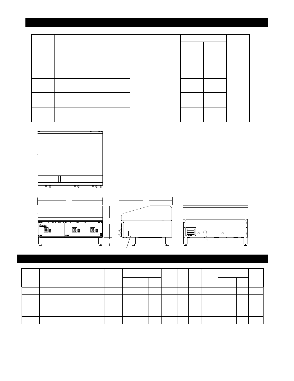
Nameplate
W
H
4”
D
1.5 Dia. Elec Knockout
(qty 2)
IL2800
EQUIPMENT SPECIFICATIONS
Model
124
136
148
160
172
Height x Width x Depth Clearance from Weight
15.0" x 24.0" x 28.2" 243 lbs. 280 lbs.
381mm x 610mm x 717mm 110 kg 127 kg
15.0" x 36.0" x 28.2" 368 lbs. 410 lbs.
381mm x 914mm x 717mm 167 kg 186 kg
15.0" x 48.0" x 28.2" Sides: 2" 483 lbs. 515 lbs.
381mm x 1219mm x 717mm Back: 2" 220 kg 234 kg
15.0" x 60.0" x 28.2" 621 lbs. 665 lbs.
381mm x 1524mm x 717mm 282 kg 302 kg
15.0" x 72.0" x 28.2" 724 lbs. 800 lbs.
381mm x 1830mm x 717mm 329 kg 364 kg
Freight
Class(Not including legs) combustible surface Actual Shipping
85
EQUIPMENT SPECIFICATIONS
Model Volts AC Hz. Ph
Kw
TOT.
Amp
1PH.
Supply
Wire
1 PH
Amp 3 Ph
124ZS 208/240 60 1/3 12 58 4 50 29 29 6
136ZS 208/240 60 1/3 18 87 2 50 50 50 6
148ZS 208/240 60 1/3 24 116 1 75 75 50 3
160ZS 208/240 60 1/3 12 58 2 50 29 29 6 18 87 2 50 50 50 6
172ZS 208/240 60 1/3 18 87 2 50 50 50 6 18 87 2 50 50 50 6
NOTICE The data plate is on the right side of the griddle. The oven voltage,
wattage,serialnumber,wiresize,andclearancespecicationsare
on the data plate. This information should be carefully read and
understood before proceeding with the installation.
4
Supply
Wire 3 PHKw
TOT.
Amp
1PH.
Supply
Wire
1 PH
Amp 3 Ph
Supply
Wire
3 PHL1 L2 L3 L1 L2 L3
2M-W1992: Electric Enviro-Zone Selectronic Griddle
Page 5

LIMITED EQUIPMENT WARRANTY
Lang Manufacturing [as well as its subsidiaries] warranties new products
to be free from defects in material and/or workmanship for a period
of one [1] year from the date of original installation, except as noted
below. Defects that occur as a result of normal use, within the time period
and limitations defined in this warranty, will at Lang’s discretion have the
parts replaced or repaired by Lang or a Lang-authorized service agency.
THIS WARRANTY IS SUBJECT TO ALL LISTED CONDITIONS.
Repairs performed under this warranty are to be performed by a Langauthorized service agency. Lang will not be responsible for charges
incurred or service performed by non-authorized repair agencies.
In all cases, the nearest Lang-authorized service agency must be used.
Lang will be responsible for normal labor charges incurred in the repair or
replacement of a warrantied product within 50 miles (80.5 km) of
an authorized service agency. Time and expense charges for anything
beyond that distance will be the responsibility of the owner. All labor
will need to be performed during regular service hours. Any overtime
premium will be charged to the owner. For all shipments outside the
U.S.A. and Canada, please see the International Warranty for specific
details.
It is the responsibility of the owner to inspect and report any shipping
damage claims, hidden or otherwise, promptly following delivery.
No mileage or travel charges will be honored on any equipment that is
deemed portable. In general, equipment with a cord and plug weighing
less than 50 lb. (22.7 kg) is considered portable and should be taken or
shipped to the closest authorized service agency, transportation
prepaid .
CONTACT
Should you require any assistance regarding the operation or
maintenance of any Lang equipment; write, phone, fax or email
our service department. In all correspondence mention the
model number and the serial number of your unit, as well as the
voltage or type of gas you are using.
Business hours are 8:00 a.m. to 4:30 p.m. Central Standard Time
Telephone 314.678.6315
Fax 314.781.2714
Email customerservice@star-mfg.com
www.langworld.com
WARRANTY EXCLUSIONS
THE FOLLOWING WILL NOT BE COVERED UNDER WARRANTY.
• Any product which has not been used, cleaned, maintained,
or installed in accordance with the directions published in the
appropriate installation sheet and/or owner's manual as well
as national and local codes, including incorrect gas, electrical,
or water connection. Lang is not liable for any unit which has been
mishandled, abused, misapplied, subjected to chlorides, harsh
chemicals, or caustic cleaners, damaged from exposure
to hard water, modified by unauthorized personnel, damaged
by flood, fire, or other acts of nature [or God], or which have
an altered or missing serial number.
• Installation, labor, and job checkouts, calibration of heat controls,
air and gas burner/bypass/pilot adjustments, gas or electrical
system checks, voltage and phase conversions, cleaning
of equipment, or seasoning of griddle surface.
• Replacement of fuses or resetting of circuit breakers, safety
controls, or reset buttons.
• Replacement of broken or damaged glass components, quartz
heating elements, and light bulbs.
• Labor charges for all removable parts in gas charbroilers and
hotplates, including but not limited to burners, grates, and radiants.
• Any labor charges incurred by delays, waiting time, or operating
restrictions that hinder a service technician’s ability to perform
service.
• Parts that fail or are damaged due to normal wear or labor for
replacement of Items that can easily be replaced during a daily
cleaning routine. such as but not limited to silicone belts, PTFE
non-stick sheets, knobs, control labels, bulbs, fuses, quartz
heating elements, baskets, racks, and grease drawers.
• Components that should be replaced when damaged or worn,
but have been field-repaired instead [eg. field-welded fry pots]
• Any loss of business or profits.
ADDITIONAL WARRANTIES
Specialty/chain specific versions may also have additional
and/or extended warranties.
PRODUCTS PARTS LABOR
Lang Chef-Series™
convection ovens
Lang Strato-Series™
convection ovens
Lang convection oven doors
[excluding hardware]
2 years 2 years
2 years 2 years
lifetime
2 years
Lang griddles and charbroilers
chrome griddle surfaces [against
original Lang parts sold to repair
The fore going warrant y is in lieu of any and a ll other warranti es expresse d or implied and c onstitutes the e ntire warranty.
5
peeling]
cast iron grates, burners,
and burner shields
Lang equipment
Service First 1 year
2M-Z22519 • Rev - • 02.2018
2 years 2 years
5 years
180 days
90 days
Page 6
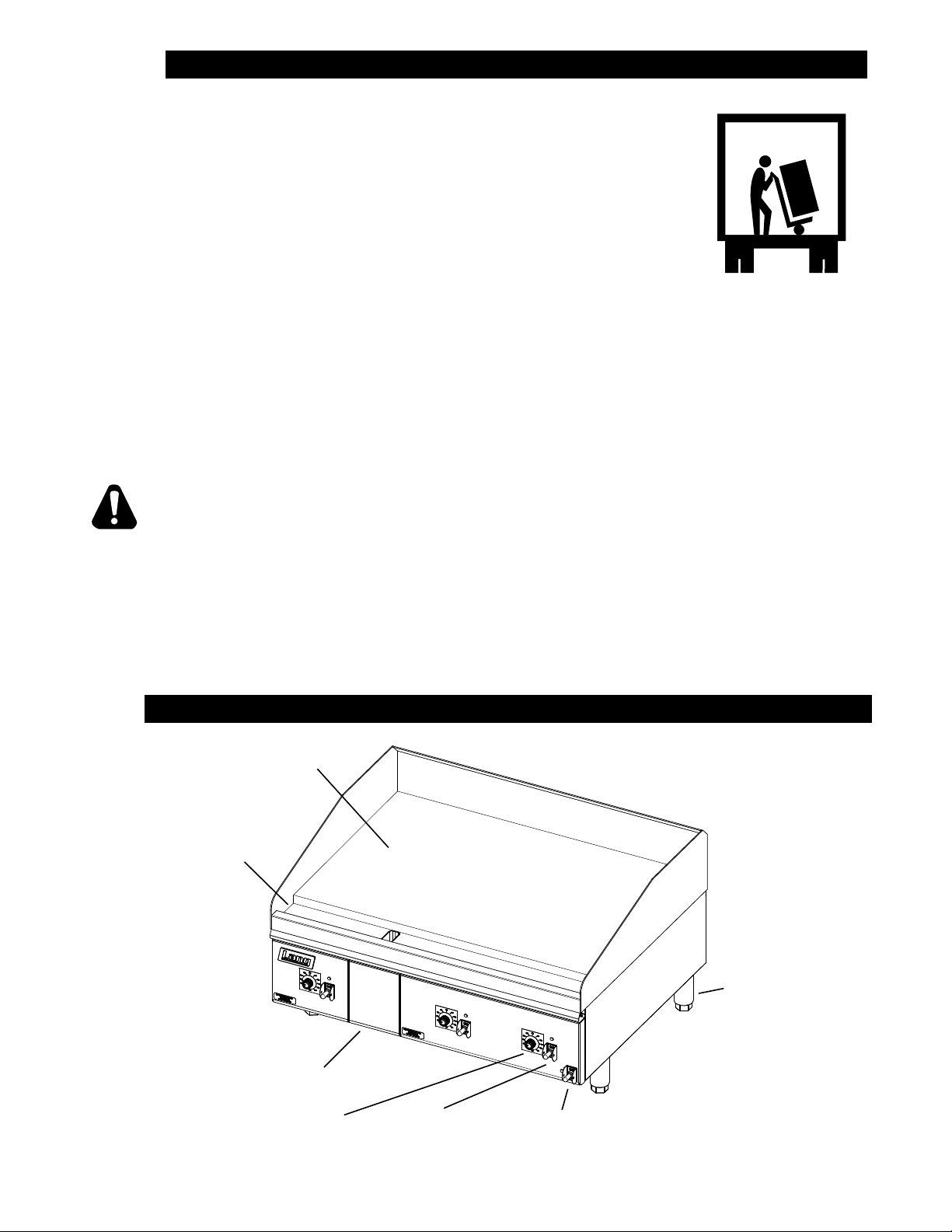
CAUTION
UNPACKING
Receiving the Griddle
Upon receipt, check for freight damage, both visible and concealed.
Visible damage should be noted on the freight bill at the time of delivery and
signed by the carrier’s agent. Concealed loss or damage means it does not
become apparent until the merchandise has been unpacked. If concealed
loss or damage is discovered upon unpacking, make a written request for
inspection by the carrier’s agent within 15 days of delivery. All packing
material should be kept for inspection. Do not return damaged
merchandise to Star Manufacturing Company. File your claim with the
carrier.
Location
Prior to un-crating, move the oven as near to its intended location as practical. The crating will help
protect the unit from the physical damage normally associated with moving it through hallways and
doorways.
Un-crating
The griddle will arrive completely assembled inside a wood frame and strapped to a skid. Cut the
straps and remove the wood frame.
The oven can now be removed from the skid.
THE UNIT IS EXTREMELY HEAVY. FOR SAFE HANDLING, INSTALLER
SHOULD OBTAIN HELP AS NEEDED, OR EMPLOY APPROPRIATE MATERIALS
HANDLING EQUIPMENT (SUCH AS A FORKLIFT, DOLLY, OR PALLET JACK)
TO REMOVE THE UNIT FROM THE SKID AND MOVE IT TO THE PLACE OF
INSTALLATION.
ANY STAND, COUNTER OR OTHER DEVICE ON WHICH OVEN WILL BE
LOCATED MUST BE DESIGNED TO SUPPORT THE WEIGHT OF THE GRIDDLE.
SHIPPING STRAPS ARE UNDER TENSION AND CAN SNAP BACK WHEN CUT.
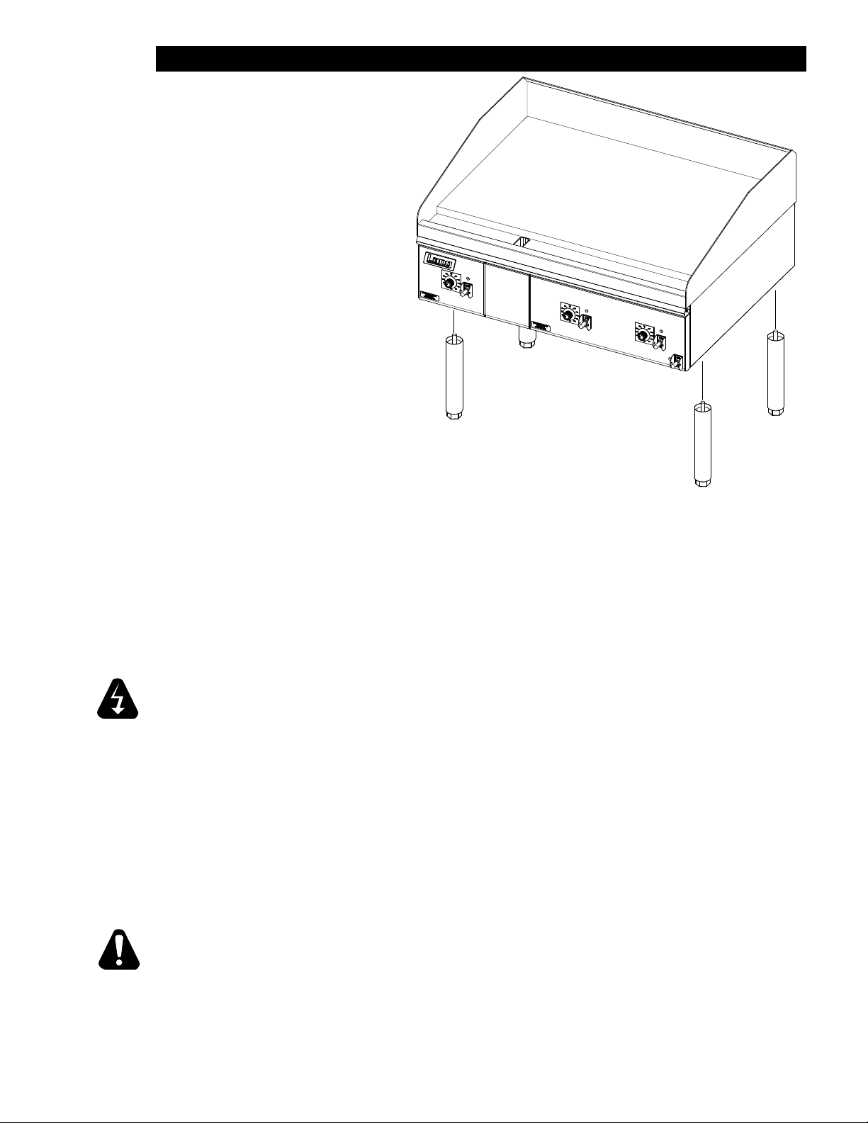
EQUIPMENT DESCRIPTION
1” Griddle Surface
Gutter
Legs
2M-W1992: Electric Enviro-Zone Selectronic Griddle
Gutter
Section
Temp. Dial
Section
Power Switch
6
Main
Power Switch
IL2801
Page 7
INSTALLATION
Leg Installation
There are four, adjustable legs
provided for Enviro-Zone griddles.
The legs are shipped in the grease
drawers of the griddle. Install them into
the threaded holes on the underside of
the griddle body.
Leveling adjustment may be done by
screwing the bottom portion of the leg
in and out.
IL2804
Above: typical leg installation.
DANGER: THIS APPLIANCE MUST BE GROUNDED AT THE TERMINAL PROVIDED.
FAILURE TO GROUND THE APPLIANCE COULD RESULT IN ELECTROCUTION
AND DEATH.
INSTALLATION OF THE UNIT MUST BE DONE BY PERSONNEL QUALIFIED TO
WORK WITH ELECTRICITY AND PLUMBING. IMPROPER INSTALLATION CAN
WARNING
CAUSE INJURY TO PERSONNEL AND/OR DAMAGE TO EQUIPMENT. UNIT
MUST BE INSTALLED IN ACCORDANCE WITH ALL APPLICABLE CODES.
NOTICE: The data plate is located behind access panel between controls and grease
drawer. The grill voltage, wattage, serial number, wire size, and clearance
specicationsareonthedataplate.Thisinformationshouldbecarefully
read and understood before proceeding with the installation.
NOTICE: The installation of any components such as a vent hood, grease extractors,
reextinguishersystems,mustconformtotheirapplicableNational,State
and locally recognized installation standards.
ALWAYS KEEP THE AREA NEAR THE APPLIANCE FREE FROM
COMBUSTIBLE MATERIALS.
KEEP FLOOR IN FRONT OF EQUIPMENT CLEAN AND DRY. IF SPILLS
CAUTION
OCCUR, CLEAN IMMEDIATELY, TO AVOID THE DANGER OF SLIPS OR FALLS.
7
Page 8

INSTALLATION cont.
Ventilation and Clearances
Standard minimum clearance from combustible construction is as follows.
2” from side
2” from back
These griddles may be set directly, without legs, on a curbed base or non-combustible surface.
If the griddle is set without legs on a non-combustible oor or a curbed base, maintain a 4-inch
back clearance.
Do not install the griddle directly against a non-combustible back wall or surface.
Do not install the griddle closer than 12 inches from an uncontrolled heat source (char broiler etc.).
Keep the appliance area free and clear of combustible material and do not obstruct the ow of
combustion or ventilation air.
Electrical Connection
There is one power supply connection on the 2, 3, and 4-foot griddles. There are two power
supply connections on 5 and 6-foot griddles. Refer to the power supply chart in the Technical
Data portion of this manual, for proper power supply size.
There is (1) one 1 1/4-inch conduit knockout on 2, 3 and 4-foot griddles located at the rear of the
griddle, through the back and the bottom of the griddle body. There are (2) two 1 1/4-inch conduit
knockouts provided on the 5 and 6-foot griddles. Use a supply wire suitable for at least 90 degree
centigrade.
This Selectronic griddle is shipped from the factory, wired for 208/240 or 480 volts, the 208/240
griddle is a dual voltage design. Jumper wires on terminal strip next to the main power supply
connection determine the griddle voltage. For a 208-volt power supply, leave the jumpers in place.
For a 240-volt power supply disconnect the jumpers as indicated on the tag on the terminal strip.
The 480-volt griddle can be operated on 480 volts only and must be specied when ordering.
Technical Data
NOMINAL AMPS PER LINE
MODEL
NUMBER
24” 12 50 28.8 28.8 43.3 25 25 21.7 12.5 12.5 57.7 50
36” 18 50 50 50 43.3 43.3 43.3 21.7 21.7 21.7 86.5 75
48” 24 75 75 50 65 65 43.3 32.5 32.5 21.7 115.5 100
60”
72”
TOTAL
K.W.
#1 18 50 50 50 43.3 43.3 43.3 21.7 21.7 21.7 86.5 75
#2 12 50 28.8 28.8 43.3 25 25 21.7 12.5 12.5 57.7 50
#1 18 50 50 50 43.3 43.3 43.3 21.7 21.7 21.7 86.5 75
#2 18 50 50 50 43.3 43.3 43.3 21.7 21.7 21.7 86.5 75
Phasing
All griddles are shipped from the
factory set up for a three-phase
service. Rearrange the wires in
the power supply terminal block to
convert the griddle to single phase.
Re-phasing the griddle is not
chargeable to Lang Manufacturing
Company as warranty. To convert
to single-phase have a Lang
Authorized Service Agent, follow
this chart.
208 Volt 240 Volt 480 Volt
PHASING BY WIRE NUMBER
MODEL
NUMBER
124S 1,4 2 3 1,3 2,6
136S 1,4 2,5 3,6 1,3,5 2,4,6
148S 1,4,7 2,5,8 3,6,9 1,3,5,7 2,4,6,8
160S #1 1,4 2,5 3,6 1,3,5 2,4,6
160S #2 1,4 2 3 1,3 2,6
172S #1 1,4 2,5 3,6 1,3,5 2,4,6
172S #2 1,4 2,5 3,6 1,3,5 2,4,6
THREE PHASE SINGLE PHASE
LINE 1 LINE 2 LINE 3 LINE 1 LINE 2
SINGLE PHASETHREE PHASE
208V 240VL1 L2 L3 L1 L2 L3 L1 L2 L3
2M-W1992: Electric Enviro-Zone Selectronic Griddle
8
Page 9

INITIAL START UP
Pre-Power On
Before starting the griddle for the rst time, clean the griddle body and cooking surface.
Use a mild soap and water solution, then rinse with clear water and dry.
Power On
Set the main power switch, located at the far left of the control panel, to the “ON” (up) position
(there are two “ON” switches on 5 and 6 foot griddles).
Set each cooking section’s power switch, located next to each temperature dial, to the “ON” (up)
position.
Set the temperature dials to 200°F.
Heat the griddle at 200°F (93°C) for 2 hours to evaporate any moisture that may be in the elements.
After 2 hours at 200°F (93°C), turn the temperature up to 350°F (176°C) for ½ hour.
After the griddle reaches 350°F (176°C) for ½ hour, turn the griddle up another 50°F (10°C) for another
½ hour and repeat this until it is at 450°F (232°C) for ½ hour.
The unit may emit a small amount of smoke as the cooking surface passes the 300°F (148°C) point.
Do not be alarmed as the smoke is caused by oils associated with the manufacturing process and will
stop when the griddle reaches 350°F (176°C).
Seasoning Cooking Surface (Non-Chrome Only)
The cooking surface must be “seasoned” in order to eliminate product sticking during cooking.
To season, heat the griddle to 250°F (121°C).
Once at 250°F (121°C), coat the cooking surface with non-salted vegetable oil.
Allow the griddle to stand at 250°F (121°C) until the cooking surface looks dry then coat it again.
Heat the griddle to 350°F (176°C) and repeat the procedure.
NOTICE: Duringtherstfewhoursofoperationyoumaynoticeasmall
amount of smoke coming off the griddle, and a faint odor from the
smoke. This is normal for a new griddle and will disappear after the
rstfewhoursofuse.
9
Page 10

OPERATION
General
The suggested time and temperature chart (below) is provided as a guide for the products listed only.
If different temperature settings are to be used, select one side of the griddle and operate at the lowest
temperature. Adjoining sections should be set at progressively higher temperatures. Do not try to
operate the end sections hot and the center sections cool.
ALWAYS KEEP THE AREA NEAR THE APPLIANCE FREE FROM
COMBUSTIBLE MATERIALS.
CAUTION
KEEP FLOOR IN FRONT OF EQUIPMENT CLEAN AND DRY. IF
SPILLS OCCUR, CLEAN IMMEDIATELY, TO AVOID THE DANGER OF
SLIPS OR FALLS.
Operations
An understanding of how the griddle sections are controlled will be a valuable aid in loading product on
your unit.
Each 12-inch section of your griddle is independently controlled by a temperature controller. The
temperature control sensor is mounted in the center of each cooking section under the griddle plate.
If the product is loaded directly over the temperature sensor, that section will turn on and the burner will
heat the entire cooking section. If the product is loaded to the side, front or back of the temperature
sensor, the thermostat will react to the temperature change much slower.
During slow periods with minimal loads, do not load directly over the thermostat sensors as this will
unnecessarily turn the burners on and overheat the remainder of the section not being utilized.
Turn the product and continue cooking
SUGGESTED TIMES AND TEMPERATURES
PRODUCTS
HAMBURGER
2 patties per LB 6 to 8
4 patties per LB 4 to 6
6 patties per LB 3 to 4
STEAKS
1/2 to 3/4 inch thick, cooked medium
3/4 to 1 inch thick, cooked medium 8 to 10
TEMPERATURE
F / C
350°F / 176°C
375°F / 190°C
TIME (MIN)
5 to 7
until it has reached its desired degree
of doneness.
Remove the product from the griddle.
When reloading the griddle, rst
use the griddle surface on which a
previous load was not placed. This
will help insure the proper griddle
temperature.
Lamb Chops
Pork Chops 6 to 8
Salmon 350°F / 176°C 6 to 8
Halibut
Snapper 6 to 8
Hash Brown Potatoes 375°F / 190°C 3 to 4
Bacon
Sausage Links or Patties 3 to 4
Ham (Pre-cooked) 375°F / 190°C 2
Eggs 275°F / 135°C 2 to 4
Note: The times and temperatures in this chart are intended as a general guide and starting
point. Your actual times and temperatures may vary from this chart.
350°F / 176°C
325°F / 162°C
350°F / 176°C
6 to 8
6 to 8
3 to 4
10
2M-W1992: Electric Enviro-Zone Selectronic Griddle
Page 11

MAINTENANCE & CLEANING
Cleaning
• Always start with a cold griddle.
• The stainless exterior can easily be cleaned using a good non-abrasive cleaner.
• Always follow the cleaner manufacturer’s instructions when using any cleaner.
• Always apply these cleaners when the griddle is cold and rub in the direction of the metal’s grain.
Griddle Surface Care (non-chromium surfaces)
It takes very little time and effort to keep the griddle attractive and performing at top efciency. If grease
is permitted to accumulate, it will form a gummy cake and then carbonize into a hard substance which is
extremely difcult to remove. To prevent this condition, the following suggestions for cleanliness should be
followed:
• After each use, scrape the griddle with a scraper or exible spatula to remove excess grease and
food. A waste drawer is provided for the scrapings. If there is an accumulation of burned on grease
and food, the griddle should be thoroughly scoured and re-seasoned. Use pumice or griddle stone
while the griddle is warm.
Do not use steel wool because of the danger of steel slivers getting into the food.
Griddle Care (Chromium Surfaces)
It takes very little time and effort to keep this Industrial Chromium griddle surface sparkling clean and
performing at top efciency. DO NOT allow grease to accumulate as it will carbonize and become difcult to
remove. To prevent this condition the following cleaning suggestions should be followed:
1. Remove excess grease and food regularly with a 4” (100mm) wide Razor Sharp type scraper and
wipe surface with a damp cloth if desired.
2. Following the scraping, for end of the day cleaning, a damp cloth and a non-silicated, nonabrasive,
non-chlorinated cleaner such as Bon-Ami may be used to wipe surface clean, followed by wiping with
a clean wet cloth.
3. Follow steps 2 and 3 from Griddle Care (Non-Chromium Surfaces) above.
CAUTION
1. Never use pumice, griddle stones, or abrasives on a chromium surface.
2. Never strike a chromium griddle surface with a sharp instrument or spatula edge.
3. Never use steel wool.
4. Never use commercial liquid grill cleaner on the griddle surface.
5. Abusing surface voids the warranty.
KEEP WATER AND SOLUTIONS OUT OF CONTROLS. NEVER SPRAY
OR HOSE CONTROL CONSOLE.
WARNING
MOST CLEANERS ARE HARMFUL TO THE SKIN, EYES, MUCOUS
MEMBRANES AND CLOTHING. PRECAUTIONS SHOULD BE TAKEN
TO WEAR RUBBER GLOVES, GOGGLES OR FACE SHIELD AND
CAUTION
NOTICE: Never leave a chlorine sanitizer in contact with stainless steel surfaces
PROTECTIVE CLOTHING. CAREFULLY READ THE WARNING AND
FOLLOW THE DIRECTIONS ON THE LABEL OF THE CLEANER TO BE
USED.
longer than 10 minutes. Longer contact can cause corrosion.
11
Page 12

TROUBLESHOOTING
Symptoms
What follows is a chart of symptoms and possible causes to aid in diagnosing faults with the griddle.
Refer to the Symptoms column to locate the type of failure then to the possible cause for the items
to be checked.
To test for a possible causes refer to the TEST section and locate the possible cause then refer
to test to identify test procedures.
SYMPTOM POSSIBLE CAUSE
No Power to Griddle
•
Whole Griddle will not heat
One Section will not heat
•
Failed Power switch
•
Failed Transformer.
Failed Power switch (for that section)
•
•
Failed Probe
• Failed Circuit board
•
Failed 12-position switch
•
Failed contactor
Failed Element.
•
Product Burning
Product Under cooked
•
Product left on griddle too long
•
Failed Probe
• Failed Circuit board
•
Failed 12-position switch
•
Product removed too soon
• Failed Probe
• Failed Circuit board
•
Failed 12-position switch
12
2M-W1992: Electric Enviro-Zone Selectronic Griddle
Page 13

TROUBLESHOOTING continued
NOTICE: Serviceonthis,oranyother,LANGappliancemustbeperformedbyqualied
personnel only. Consult your Lang Authorized Service Agent Directory or call
the factory at 314-678-6315, or WWW.LANGWORLD.COM
For the service agent nearest you.
BOTH HIGH AND LOW VOLTAGES ARE PRESENT INSIDE THIS APPLIANCE
WHEN THE UNIT IS PLUGGED/WIRED INTO A LIVE RECEPTACLE. BEFORE
WARNING
If an item on the list is followed by an asterisk (*), the work should be done by a factory authorized service
representative.
REPLACING ANY PARTS, DISCONNECT THE UNIT FROM THE ELECTRIC
POWER SUPPLY.
CAUTION
POSSIBLE
TEST
CAUSE
Product is cooked too long • No test available, operational condition
Failed Probe •
Failed Circuit board
Failed Transformer
Failed Contactor
Failed Element
USE OF ANY REPLACEMENT PARTS OTHER THAN THOSE SUPPLIED BY
LANG OR THEIR AUTHORIZED DISTRIBUTORS CAN CAUSE BODILY INJURY
TO THE OPERATOR AND DAMAGE TO THE EQUIPMENT AND WILL VOID ALL
WARRANTIES.
Check probe for proper resistance*
•
Conrm that Circuit board is getting correct
voltage and putting out correct voltage*
•
Check both Primary and Secondary coils for
correct voltage*
•
Remove the wires from the contactor coil and
check for continuity across the contactor coil
connection*
•
Ensure the contactor moveable points move
freely up and down*
•
Conrm that Elements are getting correct
voltage and have continuity*
13
Page 14

2M-61114-W71
MATERIAL
PART NO.
DR
11
2
9
SINGLE PHASE
SERVICE CONNECTIONS
WILL ALWAYS COME
TRANSFORMER POWER
CONTACTOR IN THE
GRIDDLE
FROM THE FAR RIGHT
7
8
W/D - EZONE SELECTRONIC ELECTRIC GRIDDLES
DATE/ECO DESCRIPTION OF CHANGE
MODEL NO.
REV.
TITLE
REVISIONS
3/4/14ADAMS
DATE:
°
1
±
ANGLES
CK.
:
DR
TOLERANCE: UNLESS NOTED: .xxx ± .015
FINISH
# 10 SUNNEN DRIVE
LANG MANUFACTURING
ST. LOUIS, MO. 63143, USA
INC. NO REPRODUCTION OR DISCLOSURE OF ITS CONTENTS IS PERMITTED
THIS DRAWING CONTAINS INFORMATION CONFIDENTIAL TO STAR MFG. INT'L
2
3
1
9
2
3
1
9
5
2
3
4
5
6
7
8
9
10
2
3
4
5
6
7
8
9
10
1
2
3
4
8
5
7
5
63
1
2
3
4
8
5
7
THREE PHASE
1,4 2,5 3,6 1,3,5 2,4,6
1,4 2 3 1,3 2,4
SERVICE CONNECTIONS
75
57.7
PHASE
AMPS - 1
L1 L2 L3 L1 L2 L3 L1 L2
AMP TOTALS - 3 PHASE
1,4,7 2,5,8 3,6 1,3,5,7 2,4,6,8
TOTAL
10
L3L2L1
148ZS
KW
4 4 4
4
4
L1-L2 L2-L3 L1-L3
136ZS
208V 12.0 6.0 6.0 24.0 76.3 76.3 50.0 115.4
240V 12.0 6.0 6.0 24.0 66.1 66.1 43.3 100
240V 6.0 6.0 6.0 18.0 43.3 43.3 43.3
208V 6.0 6.0 6.0 18.0 50.0 50.0 50.0 86.5
240V 6.0 6.0 12.0 43.3 25.0 25.0 50
MODEL VOLTAGE
208V 6.0 6.0 12.0 50.0 28.9 28.9
124ZS
136ZS
148ZS
2
3
1
9
6 6 6
2
3
4
5
6
7
8
9
10
1
2
3
4
8
5
7
124ZS
NOTES:
160ZS & 172ZS HAVE TWO POWER SUPPLY CONNECTIONS
160ZT: CONN #1 (RIGHT SIDE OF GRIDDLE) USE 124ZS
2
1
3
6
CONN #2 (CENTER OF GRIDDLE) USE 136ZS
CONN #2 USE 136ZT
172ZT: CONN #1 USE 136ZT
1
PILOT LIGHT
2
3
4
5
JUMPER TERMINAL BLOCK
CONTACTOR
JUMPER
GRIDDLE ELEMENTS
14
2
3
4
5
9
RTD TEMP PROBE
6
6
7
8
7
9
10
TERMINAL BLOCK
TOGGLE SWITCH
12 POSITION SWITCH
TEMP CONTROL BOARD
7
TRANSFORMER, CLASS 2
9
8
11
10
12
1
2
3
4
8
5
(ITEM 4)
JUMPER
REMOVE
ELEMENT HOOKUP
208V 240V
INSTALL
(ITEM 4)
JUMPER
2M-W1992: Electric Enviro-Zone Selectronic Griddle
Page 15

15
Page 16

1
SK2763 Rev. - 3/10/14
Electric EnviroZone Selectronic Griddle
2
3
4
5
6
23
24
10
19
20
21
22
18
11
12
13
10
15
17 16
7
8
9
10
35
34
10
33
14
32
28
11
31
30
29
27
10
26
25
2M-W1992: Electric Enviro-Zone Selectronic Griddle
Model: 136ZS
16
Page 17

PARTS LIST May 14, 2014, Rev A
Model: 124ZS, 124ZSD EnviroZone Selectronic Griddle
Fig No. Part Number Quantity Description Application
1
2
3
4
5
6
7 K9-XL-532 12 BOLT AND SCREW ASSY
8 2E-41100-17 2 TEMP PROBE SEL LG GRIDDLE
9 K9-142-441 2 RTD PROBE HOLDER
10 2C-20102-12 22 SCRW PHD ST 10-32X3/8
11 2C-20301-11 14 NUT HEX 8-32 PLTD
12 2E-30701-04 2 CONTC 2POLE 30A 24VAC
13 K9-142-152-W41 2 CONTACTOR BRACKET
14 2E-40101-W19 2 CIRBD SI TEMP CONTROL
15 2K-70801-07 6 SPACER SUPPORT 1/2LG
16 2E-30304-22 2 SWTCB175-450°F w/41100-13
17 2C-20602-04 3 TINNERMAN SPD NUT 1/8 DIA
18 K9-142-242 1 FRONT PANEL WELD ASSY LEFT ZS
19 2M-60301-43 1 DIE CAST PLT LANG SATIN
20 2M-60301-29 2 PNLLBL SELCT SWTDIAL 450o
21 2R-70701-28 2 KNB BLK 1/4BUSH2SETSCW@90
22 Y9-31601-01-1 3 PILOT LT 250V W/TIN CLIP
23
24 K9-50303-18 1 GREASE DRAWER-EZONE GRID
25 2I-05-07-0013 3 BOOT SWITCH
26 2M-12-07-0038 3 LABEL ON & OFF
27 Z1-70-07-0343 3 SWITCH GUARD
28 2E-30303-06 3 SWT TOG ON-ON DPDT BLK
29 K9-142-237-21 1 FRONT PNL WELD, RIGHT ZS
30 K9-142-151-W2 1 24V XFMR AND BRKT ASSY
31 2E-31400-07 1 XFORMR120-208-240/24V40VA
32 2A-72500-20 4 LEG 10.25 WITH ADJ HEX
33 K9-XL-507-2 1 REAR COVER - ZT
34 2C-20103-01 2 SCRW SM PLT 10X7/8 PHIL
35 2E-30500-02 1 TRM STRIP 4POLE 30A 600V
NI 2E-30500-07 1 TRM BLOCK 3PLELRGE 125AM
NI 2M-61114-W71 0 W/D ZS SEL GRID 208/240
K9-142-201-32
K9-142-201-323 GRIDDLE PLATE ASSY-2’ ZTD 124ZSD
2N-11030-30
2N-11030-30-1 PERIMETER ELEMENT-30”D 124ZSD
2N-11030-29
2N-11030-29-1 DUAL VOLTAGE ELEMENT-30”D 124ZSD
K9-XL-429
K9-XL-429-1 ELEMENT PLATE GUIDE WELD 124ZSD
K9-XL-424-1
K9-XL-424-2 ELEMENT PAN INSUL 30” DEEP 124ZSD
K9-XL-434-1
K9-XL-434-2 ELEMENT PAN SPOTWELD-30”D 124ZSD
K9-141-161-3W1
K9-141-161-W1
1
2
2
2
2
2
1 GREASE DRAWER SLIDE WELD
GRIDDLE PLATE ASSY - 2’ZT 124ZS
ELMNT GRID 208V 1257W 124ZS
ELE GRD 208/240V4.5KW/6KW 124ZS
ELEMENT PLATE GUIDE WLDMT 124ZS
ELEMENT PAN INSULATION 124ZS
ELEMENT PAN SPOTWELD 124ZS
IMPORTANT: WHEN ORDERING, SPECIFY VOLTAGE OR TYPE GAS DESIRED PAGE 1
INCLUDE MODEL AND SERIAL NUMBER OF 1
Some items are included for illustrative purposes only and in certain instances may not be available.
17
Page 18

PARTS LIST May 14, 2014, Rev A
Model: 136ZS EnviroZone Selectronic Griddle
Fig No. Part Number Quantity Description Application
K9-142-201-33
1
K9-142-201-333 GRIDDLE PLATE ASSY -3’ ELEC 136ZSD
2N-11030-30
2
2N-11030-30-1 PERIMETER ELEMENT-30”D 136ZSD
2N-11030-29
3
2N-11030-29-1 DUAL VOLTAGE ELEMENT-30”D 136ZSD
K9-XL-429
4
K9-XL-429-1 136ZSD
K9-XL-424-1
5
K9-XL-424-2 ELEMENT PAN INSUL 30” DEEP 136ZSD
K9-XL-434-1
6
K9-XL-434-2 ELEMENT PAN SPOTWELD-30”D 136ZSD
7 K9-XL-532 18 BOLT AND SCREW ASSY
8 2E-41100-17 3 TEMP PROBE SEL LG GRIDDLE
9 K9-142-441 3 RTD PROBE HOLDER
10 2C-20102-12 25 SCRW PHD ST 10-32X3/8
11 2C-20301-11 14 NUT HEX 8-32 PLTD
12 2E-30701-04 3 CONTC 2POLE 30A 24VAC
13 K9-142-152-W41 3 CONTACTOR BRACKET
14 2E-40101-W19 3 CIRBD SI TEMP CONTROL
15 2K-70801-07 9 SPACER SUPPORT 1/2LG
16 2E-30304-22 3 SWTCB175-450°F w/41100-13
17 2C-20602-04 4 TINNERMAN SPD NUT 1/8 DIA
18 K9-142-242 1 FRONT PANEL WELD ASSY, LEFT ZS
19 2M-60301-43 1 DIE CAST PLT LANG SATIN
20 2M-60301-29 3 PNLLBL SELCT SWTDIAL 450o
21 2R-70701-28 3 KNB BLK 1/4BUSH2SETSCW@90
22 Y9-31601-01-1 4 PILOT LT 250V W/TIN CLIP
23
24 K9-50303-18 1 GREASE DRAWER-EZONE GRID
25 2I-05-07-0013 4 BOOT SWITCH
26 2M-12-07-0038 4 LABEL ON & OFF
27 Z1-70-07-0343 4 SWITCH GUARD
28 2E-30303-06 4 SWT TOG ON-ON DPDT BLK
29 K9-142-246 1 FRONT PANEL WELD ASSY, RIGHT ZS
30 K9-142-151-W2 1 24V XFMR AND BRKT ASSY
31 2E-31400-07 1 XFORMR120-208-240/24V40VA
32 2A-72500-20 4 LEG 10.25 WITH ADJ HEX
33 K9-XL-507-2 1 REAR COVER - ZT
34 2C-20103-01 2 SCRW SM PLT 10X7/8 PHIL
35 2E-30500-03 1 TRM STRIP 6POLE 30A 300V
NI 2E-30500-07 1 TRM BLOCK 3PLELRGE 125AM
NI 2M-61114-W71 0 W/D ZS SEL GRID 208/240
K9-141-161-3W1
K9-141-161-W1 GREASE DRAWER SLIDE WELD 136ZS
1
3
3
3 ELEMENT PLATE GUIDE WLDMT
3
3
1
GRIDDLE PLATE ASSY - 3’ZT 136ZS
ELMNT GRID 208V 1257W 136ZS
ELE GRD 208/240V4.5KW/6KW 136ZS
136ZS
ELEMENT PAN INSULATION 136ZS
ELEMENT PAN SPOTWELD 136ZS
GREASE DRAWER SLIDE WELD 136ZSD
2M-W1992: Electric Enviro-Zone Selectronic Griddle
IMPORTANT: WHEN ORDERING, SPECIFY VOLTAGE OR TYPE GAS DESIRED PAGE 1
INCLUDE MODEL AND SERIAL NUMBER OF 1
Some items are included for illustrative purposes only and in certain instances may not be available.
18
Page 19

PARTS LIST May 14, 2014, Rev A
Model: 148ZS EnviroZone Selectronic Griddle
Fig No. Part Number Quantity Description Application
K9-142-201-343
1
K9-142-201-43 GRIDDLE PLATE ASSY - 4’ZT 148ZS
2N-11030-30
2
2N-11030-30-1 PERIMETER ELEMENT-30”D 148ZSD
2N-11030-29
3
2N-11030-29-1 DUAL VOLTAGE ELEMENT-30”D 148ZSD
K9-XL-429
4
K9-XL-429-1 148ZSD
K9-XL-424-1
5
K9-XL-424-2 ELEMENT PAN INUSL 30” DEEP 148ZSD
K9-XL-434-1
6
K9-XL-434-2 ELEMENT PAN SPOTWELD-30”D 148ZSD
7 K9-XL-532 24 BOLT AND SCREW ASSY
8 2E-41100-17 4 TEMP PROBE SEL LG GRIDDLE
9 K9-142-441 4 RTD PROBE HOLDER
10 2C-20102-12 35 SCRW PHD ST 10-32X3/8
11 2C-20301-11 18 NUT HEX 8-32 PLTD
12 2E-30701-04 3 CONTC 2POLE 30A 24VAC
13 K9-142-152-W41 4 CONTACTOR BRACKET
14 2E-40101-W19 4 CIRBD SI TEMP CONTROL
15 2K-70801-07 12 SPACER SUPPORT 1/2LG
16 2E-30304-22 4 SWTCB175-450°F w/41100-13
17 2C-20602-04 5 TINNERMAN SPD NUT 1/8 DIA
18 K9-142-242 1 FRONT PNL WELD ASSY, LEFT ZS
19 2M-60301-43 1 DIE CAST PLT LANG SATIN
20 2M-60301-29 4 PNLLBL SELCT SWTDIAL 450o
21 2R-70701-28 4 KNB BLK 1/4BUSH2SETSCW@90
22 Y9-31601-01-1 5 PILOT LT 250V W/TIN CLIP
23
24 K9-50303-18 2 GREASE DRAWER-EZONE GRID
25 2I-05-07-0013 5 BOOT SWITCH
26 2M-12-07-0038 5 LABEL ON & OFF
27 Z1-70-07-0343 5 SWITCH GUARD
28 2E-30303-06 5 SWT TOG ON-ON DPDT BLK
29
30 K9-142-151-W2 1 24V XFMR AND BRKT ASSY
31 2E-31400-07 1 XFORMR120-208-240/24V40VA
32 2A-72500-20 4 LEG 10.25 WITH ADJ HEX
33 K9-XL-507-2 1 REAR COVER - ZT
34 2C-20103-01 2 SCRW SM PLT 10X7/8 PHIL
35
NI 2E-30500-07 1 TRM BLOCK 3PLELRGE 125AM
NI 2M-61114-W71 0 W/D ZS SEL GRID 208/240
K9-141-161-3W1
K9-141-161-W1 148ZS
K9-142-232-21
K9-142-232-61 FRONT PANEL WELD ASSY, CENTER ZS
2E-30500-03
2E-30500-22 TEM STRIP 8POLE 50A/250V
1
4
4
4 ELEMENT PLATE GUIDE WLDMT
4
4
2 GREASE DRAWER SLIDE WELD
1
1
GRIDDLE PLATE ASSY-4’ ZTD 148ZSD
ELMNT GRID 208V 1257W 148ZS
ELE GRD 208/240V4.5KW/6KW 148ZS
148ZS
ELEMENT PAN INSULATION 148ZS
ELEMENT PAN SPOTWELD 148ZS
148ZSD
FRONT PANEL WELD ASSY, RIGHT
TRM STRIP 6POLE 30A 300V
IMPORTANT: WHEN ORDERING, SPECIFY VOLTAGE OR TYPE GAS DESIRED PAGE 1
INCLUDE MODEL AND SERIAL NUMBER OF 1
Some items are included for illustrative purposes only and in certain instances may not be available.
19
Page 20

PARTS LIST May 14, 2014, Rev A
Model: 160ZS EnviroZone Selectronic Griddle
Fig No. Part Number Quantity Description Applications
1
2
3
4
5
6
7 K9-XL-532 30 BOLT AND SCREW ASSY
8 2E-41100-17 5 TEMP PROBE SEL LG GRIDDLE
9 K9-142-441 5 RTD PROBE HOLDER
10 2C-20102-12 42 SCRW PHD ST 10-32X3/8
11 2C-20301-11 24 NUT HEX 8-32 PLTD
12 2E-30701-04 5 CONTC 2POLE 30A 24VAC
13 K9-142-152-W41 5 CONTACTOR BRACKET
14 2E-40101-W19 5 CIRBD SI TEMP CONTROL
15 2K-70801-07 15 SPACER SUPPORT 1/2LG
16 2E-30304-22 5 SWTCB175-450°F w/41100-13
17 2C-20602-04 6 TINNERMAN SPD NUT 1/8 DIA
18 K9-142-242 1 FRONT PANEL WELD ASSY, LEFT ZS
19 2M-60301-43 1 DIE CAST PLT LANG SATIN
20 2M-60301-29 5 PNLLBL SELCT SWTDIAL 450o
21 2R-70701-28 5 KNB BLK 1/4BUSH2SETSCW@90
22 Y9-31601-01-1 6 PILOT LT 250V W/TIN CLIP
23
24 K9-50303-18 2 GREASE DRAWER-EZONE GRID
25 2I-05-07-0013 6 BOOT SWITCH
26 2M-12-07-0038 6 LABEL ON & OFF
27 Z1-70-07-0343 6 SWITCH GUARD
28 2E-30303-06 6 SWT TOG ON-ON DPDT BLK
29
30 K9-142-151-W2 2 24V XFMR AND BRKT ASSY
31 2E-31400-07 2 XFORMR120-208-240/24V40VA
32 2A-72500-20 4 LEG 10.25 WITH ADJ HEX
33 K9-XL-507-2 2 REAR COVER - ZT
34 2C-20103-01 4 SCRW SM PLT 10X7/8 PHIL
35
NI 2E-30500-07 2 TRM BLOCK 3PLELRGE 125AM
NI 2M-61114-W71 0 W/D ZS SEL GRID 208/240
K9-142-201-353
K9-142-201-53 GRIDDLE PLATE ASSY - 5’ZT 160ZS
2N-11030-30
2N-11030-30-1 PERIMETER ELEMENT-30”D 160ZSD
2N-11030-29
2N-11030-29-1 DUAL VOLTAGE ELEMENT-30”D 160ZSD
K9-XL-429
K9-XL-429-1 ELEMENT PLATE GUIDE WLDMT 160ZSD
K9-XL-424-1
K9-XL-424-2 ELEMENT PAN INSUL 30” DEEP 160ZSD
K9-XL-434-1
K9-XL-434-2 ELEMENT PAN SPOTWELD-30”D 160ZSD
K9-141-161-3W1
K9-141-161-W1 160ZS
K9-142-232-21
K9-142-232-51 FRONT PANEL WELD ASSY CENTER ZS
2E-30500-02 1 TRM STRIP 4POLE 30A 600V
2E-30500-03 2 TRM STRIP 6POLE 30A 300V
1
5
5
5
5
5
2 GREASE DRAWER SLIDE WELD
1
GRIDDLE PLATE ASSY-5’ ZTD 160ZSD
ELMNT GRID 208V 1257W 160ZS
ELE GRD 208/240V4.5KW/6KW 160ZS
ELEMENT PLATE GUIDE WLDMT 160ZS
ELEMENT PAN INSULATION 160ZS
ELEMENT PAN SPOTWELD 160ZS
160ZSD
FRONT PANEL WELD ASSY RIGHT ZS
2M-W1992: Electric Enviro-Zone Selectronic Griddle
IMPORTANT: WHEN ORDERING, SPECIFY VOLTAGE OR TYPE GAS DESIRED PAGE 1
INCLUDE MODEL AND SERIAL NUMBER OF 1
Some items are included for illustrative purposes only and in certain instances may not be available.
20
Page 21

PARTS LIST May 14, 2014, Rev A
Model: 172ZS EnviroZone Selectronic Griddle
Fig No. Part Number Quantity Description Application
1 K9-142-201-63 1 GRIDDLE PLATE ASSY - 6’ZT
2N-11030-30
2
2N-11030-30-1 PERIMETER ELEMENT-30”D 172ZSD
2N-11030-29
3
2N-11030-29-1 ELEMT GRID 208/240V 172ZSD
K9-XL-429
4
K9-XL-429-1 172ZSD
K9-XL-424-1
5
K9-XL-424-2 ELEMENT PAN INSUL 30” DEEP 172ZSD
K9-XL-434-1
6
K9-XL-434-2 ELEMETN PAN SPOTWELD-30”D 172ZSD
7 K9-XL-532 36 BOLT AND SCREW ASSY
8 2E-41100-17 6 TEMP PROBE SEL LG GRIDDLE
9 K9-142-441 6 RTD PROBE HOLDER
10 2C-20102-12 47 SCRW PHD ST 10-32X3/8
11 2C-20301-11 28 NUT HEX 8-32 PLTD
12 2E-30701-04 6 CONTC 2POLE 30A 24VAC
13 K9-142-152-W41 6 CONTACTOR BRACKET
14 2E-40101-W19 6 CIRBD SI TEMP CONTROL
15 2K-70801-07 18 SPACER SUPPORT 1/2LG
16 2E-30304-22 6 SWTCB175-450°F w/41100-13
17 2C-20602-04 7 TINNERMAN SPD NUT 1/8 DIA
18 K9-142-242-1 1 FRONT PANEL WELD ASSY, LEFT ZS
19 2M-60301-43 1 DIE CAST PLT LANG SATIN
20 2M-60301-29 6 PNLLBL SELCT SWTDIAL 450o
21 2R-70701-28 6 KNB BLK 1/4BUSH2SETSCW@90
22 Y9-31601-01-1 7 PILOT LT 250V W/TIN CLIP
23
24 K9-50303-18 2 GREASE DRAWER-EZONE GRID
25 2I-05-07-0013 7 BOOT SWITCH
26 2M-12-07-0038 7 LABEL ON & OFF
27 Z1-70-07-0343 7 SWITCH GUARD
28 2E-30303-06 7 SWT TOG ON-ON DPDT BLK
29 K9-142-232-61 1 FRONT PNL WELD. CENTER ZS
29 K9-142-246 1 FRONT PANEL WELD ASSY, RIGHT ZS
30 K9-142-151-W2 2 24V XFMR AND BRKT ASSY
31 2E-31400-07 2 XFORMR120-208-240/24V40VA
32 2A-72500-20 4 LEG 10.25 WITH ADJ HEX
33 K9-XL-507-2 2 REAR COVER - ZT
34 2C-20103-01 4 SCRW SM PLT 10X7/8 PHIL
35 2E-30500-03 2 TRM STRIP 6POLE 30A 300V
NI 2E-30500-07 2 TRM BLOCK 3PLELRGE 125AM
NI 2M-61114-W71 0 W/D ZS SEL GRID 208/240
K9-141-161-3W1
K9-141-161-W1 172ZS
6
6
6 ELEMENT PLATE GUIDE WLDMT
6
6
2 GREASE DRAWER SLIDE WELD
ELMNT GRID 208V 1257W 172ZS
ELE GRD 208/240V4.5KW/6KW 172ZS
172ZS
ELEMENT PAN INSULATION 172ZS
ELEMENT PAN SPOTWELD 172ZS
172ZSD
IMPORTANT: WHEN ORDERING, SPECIFY VOLTAGE OR TYPE GAS DESIRED PAGE 1
INCLUDE MODEL AND SERIAL NUMBER OF 1
Some items are included for illustrative purposes only and in certain instances may not be available.
21
Page 22

STAR INTERNATIONAL HOLDINGS INC. COMPANY
Star - Lang - Wells - Toastmaster
265 Hobson Street - Smithville, Tennessee 37166 U.S.A.
(314) 678-6303 www.langworld.com
 Loading...