

Page 1

NXT
1
S
N -
TIO
N TRU
G I
N S C
T
A I
ER
P
O
Y A
E
w
S
P L
M
n .
. l a e
I I
F
C
c
y . u
400W TU E BAS GUIT
L A
w w
A I
AR MPLIF
O
T NN I
A
o
k
ERB
Page 2

IMPORTANT SAFETY INSTRUCTIONS
WARNING: When using electric products, basic cautions should always be followed, including the following.
NXTNX
1. Read all safety and operating instructions before using this product
2. The product should be powered by a three pin `grounded (or earthed) plug connected to a power socket with a grounded earth outlet.
3. All safety and operating instructions should be retained for future reference
4. Obey all cautions in the Operating instructions and on the back of the unit
5. All operating instructions should be followed
6. This product should not be used near water, i.e. a bathtub, sink, swimming pool, wet basement, etc.
7. This product should be located so that its position does not interfere with its proper ventilation. It should not be placed flat against a wall or placed in a built up enclosure that
will impede the flow of cooling air.
8. This product should not be placed near a source of heat such as stove, radiator, or another heat producing amplifier.
9. Connect only to a power supply of the type marker on the unit adjacent to the power supply cord.
10. Never break off the ground pin on a power supply cord.
11. Power supply cords should always be handled carefully. Never walk or place equipment on power supply cords. Periodically check cords for cuts or signs of stress, especially at
the plug and the point where the chord exits the unit.
12. The power supply cord should be unplugged when the unit is to be unused for long periods of time.
13. If this product is to be mounted in an equipment rack, rear support should be provided.
14. The user should allow easy access to any mains plug, mains coupler and mains switch used in conjunction with this unit thus making it readily operable.
15. Metal parts can be cleaned with a damp cloth. The vinyl covering used on some units can be cleaned with a damp cloth or ammonia based household cleaner if necessary.
Disconnect the unit from the power supply before cleaning.
16. Care should be taken so that objects do not fall and liquids are not spilled into the unit through any ventilation holes or openings. On no account place drinks on the unit.
17. A qualified service technician should check the unit if:
!
The power cord has been damaged
!
Anything has fallen or spilled into the unit
!
The unit does not appear to operate correctly
!
18. The user should not attempt to service the equipment. All service work is done by a qualified service technician.
19. Exposure to extremely high noise levels may cause a permanent hearing gloss. Individuals vary considerably in susceptibility to noise induced hearing loss, but nearly everyone
Duration Per Day In Hours Sound Level dBA, slow response
According to OSHA, any exposure in excess of the above permissible limits could result in some hearing loss. Ear plugs or protectors in the ear canals or over the ears must be
worn when operating this amplification system in order to prevent a permanent hearing loss if exposure exceeds the limits set forth above. To ensure against potentially dangerous
exposure to high sound pressure levels it is recommended that all persons exposed to equipment capable of producing high sound pressure levels such as this amplification system be
protected by hearing protectors while this unit is in operation.
The unit has been dropped or the enclosure damaged.
will lose some hearing if exposed to sufficiently intense noise for a sufficient time. The U.S. Government's Occupational Safety and Health Administration (OSHA) has specified
the following permissible noise level exposure.
8 90
6 92
4 95
3 97
2 100
1 ½ 102
1 105
½ 110
¼ or less 115
SAVE THESE INSTRUCTIONS
Page 2 /24
Page 3
T
CAUTION:
ATTENTION:
PRECAUCION:
VORSICHT:
WARNING:
ADVERTISSEMENT:
ADVERTENCIA:
ACHTUNG:
Intended to alert the user to the presence of uninsulated ‘Dangerous Voltage’
within the products enclosure that may be sufficient to constitute a risk of
electrical shock to persons.
Ce symbole est utililise pur indiquer a l’utilisateur de ce produit de tension nonisolee dangereuse pouvant etre d’intensite suffisante pour constituer un risque
de choc electrique.
Este simbolo tiene el proposito de alertar al usuario de la presencia de ‘(voltaje)
peligroso’ que no tiene aislamiento dentro de la caja del producto que puede
tener una magnitud suficiente como para constituir riesgo de corrientazo.
Dieses Symbol soll den Anwender vor unsolierten gefahrlichen Spannungen
innerhalb des Gehauses warnen, die von Ausrichender Starke sind, um einen
elektrischen Schlag verursachen zu konnen.
Intended to alert the user of the presence of important operating and
maintenance (Servicing) instructions in the literature accompanying the product.
Dieses Symbol soll den Anwender vor unsolierten gefahrlichen Spannungen
innerhalb des Gehauses warnen, die von Ausrichender Starke sind, um einen
elektrischen Schlag verursachen zu konnen.
Este simbolo tiene el proposito de la alertar al usario de la presencis de
instrucccones importantes sobre la operacion y mantenimiento en la literatura
que viene conel producto.
Dieses Symbol soll den Benutzer auf wichtige Instruktionen in der
Bedienungsanleitung aufmerksam machen, die Handhabung und Wartung des
Produkts betreffen.
Risk of electrical shock - DO NOT OPEN.
To reduce the risk of electrical shock, do not remove the cover. No user
serviceable parts inside. Refer servicing to qualified personnel.
Risques de choc electrique - NE PAS OUVIRIR
Afin de reduire le risque de choc electrique, ne pas enlever le couvercle. II ne
se trouve a l’interieur aucune piece pouvant etre reparee par l’utilisateur.
Confier l’entretien a un personnel qualifie.
Riesgo de corrientazo - no abra
Para disminuir el risego de carrientazo, no abra la cubierta. No hay piezas
adentro que el pueda reparar. Deje todo mantenimiento a los tecnicos
calificadod.
Risiko - Elektrischer Schlag! Nicht offen!
Um das Risiko eines elektrischen Schlages zu vermeiden, nicht die Abdeckung
enfernen. Es befinden sich keine Teile darin, die vom Anwender repariert
werden Konnten. Reparaturen nur von qualifiziertem Fachpersonal durchfuhren
lassen.
To prevent electrical shock or fire hazard, do not expose this appliance to rain
or moisture. Before using this appliance please read the operating instructions
for further warnings.
Afin de prevenir les risques de decharge electrique ou de feu, n’exposez pas
cet appareil a la pluie ou a l’humidite. Avant d’utiliser cet appareil, lisez les
advertissments supplentaires situes dans le guide.
Para evitar corrientazos o peligro de incendio, no deja expuesto a la lluvia o
humedad este aparato Antes de usar este aparato, lea mas advertcias en la
guia de operacion.
Um einen elektrischen Schalg oder Feuergefahr zu vermeiden, sollte dieses
Gerat nicht dem Regen oder Feuchtigkeit ausgesetzt werden. Vor
Inbetriebnahme unbedingt die Bedienungsanleitung lesen.
BEFORE SWITCHING ON
After unpacking your amplifier check that it is factory fitted with a three pin
'grounded' (or earthed) plug. Before plugging into the power supply ensure you
are connecting to a grounded earth outlet.
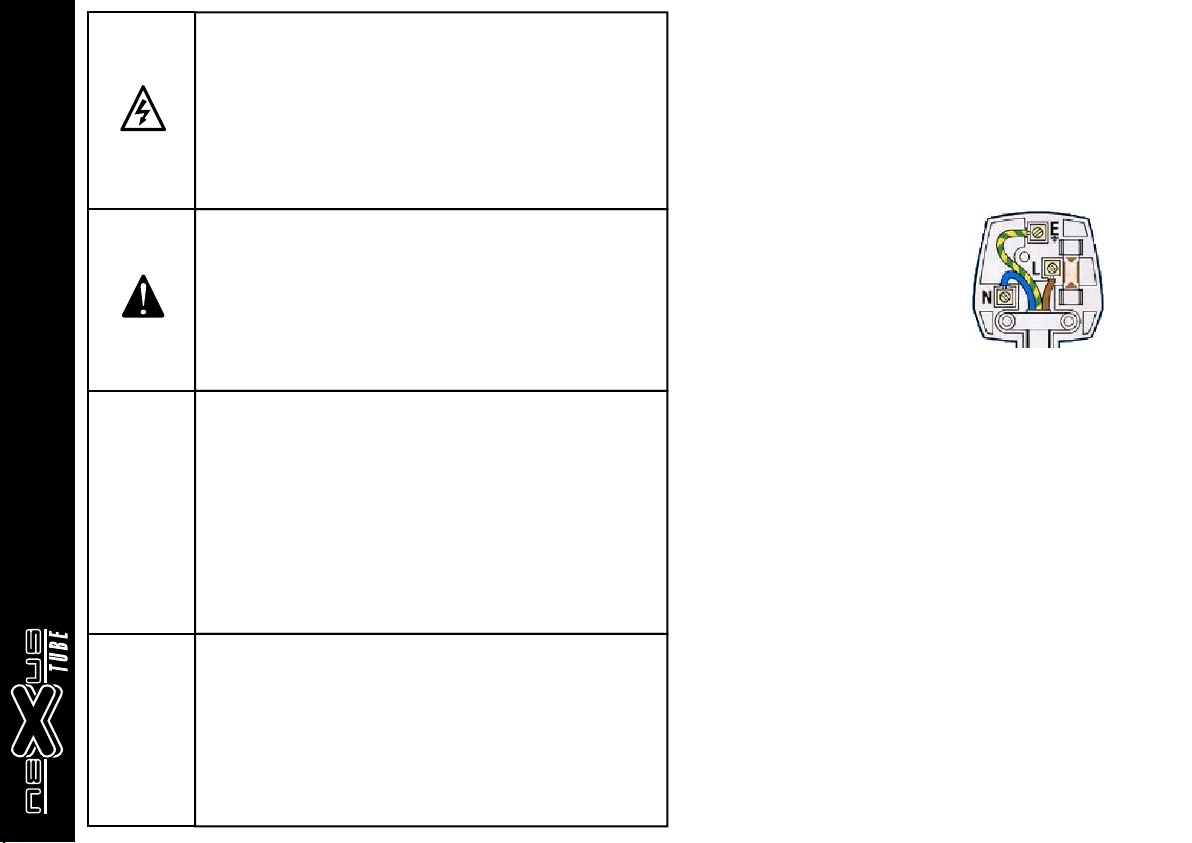
If you should wish to change the factory fitted plug yourself, ensure that the wiring
convention applicable to the country where the amplifier is to be used is strictly
conformed to. As an example in the United Kingdom the cable colour code for
connections are as follows.
EARTH or GROUND GREEN/YELLOW
NEUTRAL - BLUE
LIVE - BROWN
NOTE
This manual has been written for easy access of information. The front and rear
panels are graphically illustrated, with each control and feature numbered. For a
description of the function of each control feature, simply check the number with
the explanations adjacent to each panel.
Your Laney amplifier has undergone a thorough two stage, pre-delivery inspection,
involving actual play testing.
When you first receive your Laney guitar amplifier, follow these simple procedures:
(i) Ensure that the amplifier is the correct voltage for the country it is to be used in.
ii) Connect your instrument with a high quality shielded instrument cable. You
have probably spent considerable money on your amplifier and guitar - don’t use
poor quality cable it won’t do your gear justice.
Please retain your original carton and packaging so in the unlikely event that some
time in the future your amplifier should require servicing you will be able to return it
to your dealer securely packed.
Care of your Laney amplifier will prolong it's life.....and yours!
Page 3 /24
Page 4
T
NX
Laney
Dear Player,
Thank you very much for purchasing your new Laney product and becoming part of the worldwide Laney family. Each and every
Laney unit is designed and built with the utmost attention to care and detail, so I trust yours will give you many years of
enjoyment.
Laney products have a heritage which stretches back to 1967 when I first began building valve amplifiers in my parent’s garage.
Since then we have moved on from strength to strength developing an extensive range of guitar, bass, public address and
keyboard amplification products along with a list of Laney endorsees that includes some of the world’s most famous and
respected musicians. At the same time we believe we have not lost sight of the reason Laney was founded in the first place - a
dedication to building great sounding amplification for working musicians.
Warm Regards,
Introduction
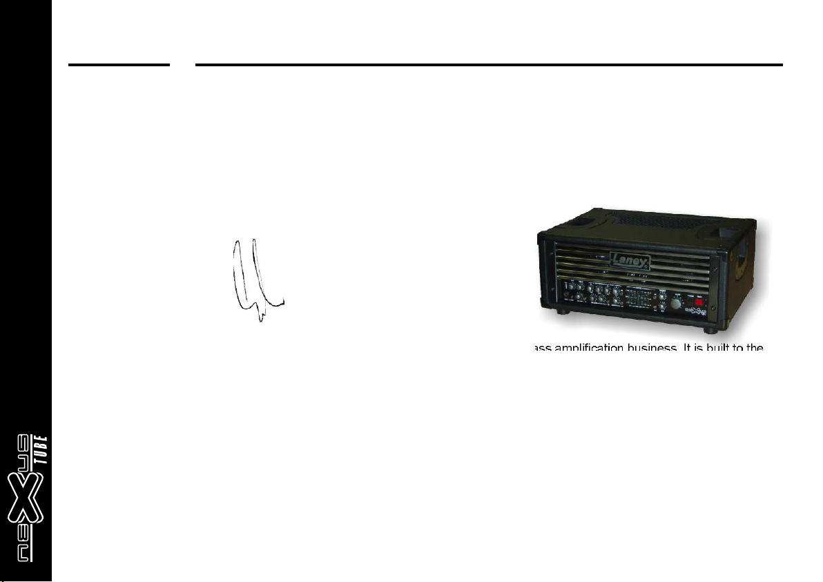
The Nexus Tube amplifier is the culmination of our 40 years of experience in the bass amplification business. It is built to the
highest professional standards using the best available parts.
Through out the design we have considered the requirements of the professional player who not only requires great sounds but
also the utmost reliability. To this end we have used the best tubes available, gold plated circuit boards, gold relays for all signal
switching, massive oversized toroidal transformers plus an overall feature set and sound second to none.
The amplifier is assembled in our UK factory by our very experienced staff with great attention to detail and inspection. It is then
electrically bench tested. Following this, it is put through extensive burn in procedures over many hours. Afterwards it goes back
to the test bench for a further re-check and final calibration.Only when it has successfully passed these stages is it then put into
its cabinet.
Then comes the most important part of all; actual play testing. One of our experienced bass guitarists spends a long time putting
the amplifier though its paces, checking all the sounds and functions are perfect. Only then does it get the seal of approval to be
carefully packed and shipped.
We hope you enjoy using your Nexus amplifier as much as we have enjoyed designing and building it.
Best wishes from all at Laney.
OPERATING INSTRUCTIONS
Lyndon Laney CEO
Page 4 /24
Page 5

T
NX
Laney
NXT USER TIPS & QUICK START
Connecting up your rig: Check your amplifier is the correct working voltage for the area you are in. Ensure you use the earthed power cord supplied
with your amplifier to connect to the power supply. Make sure the supply socket you are using is an earthed/grounded type.
Ensure you connect your speakers to the appropriate impedance socket with good quality speaker cable and connectors before
switching on your amplifier. If not using Nexus speakers ensure they are of sufficient power handling capacity and correct
impedance.
Quick start: Make sure the volume control is at minimum. The gain controls are at minimum. The EQ and graphic slider controls are at the
centre zero position and none of the push switches are illuminated. Turn your amplifier on with the power switch making sure that
the standby switch is in the standby position first. After a minute or so turn on the standby switch to the Run position. Plug in your
guitar using a good quality screened lead. Press the FET channel select button. Play your bass guitar and adjust the FET Gain
control until your playing lights the amber led in the bar graph display and only very occasionally on loud peaks the Red. If you
find that the gain control has to be set quite low to achieve this, try pressing in the pad switch to lower the input sensitivity. Now
advance the Volume control to the desired listening level. Apply tone correction as desired but try to use small amounts of boost
and cut to your sound. Over correction will nearly always sound bad. Don't forget most of the controls have cut and boost don't
boost them all, cut sounds good too especially in the mid range. Try to always use the minimum tone correction to get your
desired sound. As you adjust your tone you may need to readjust the gain control to maintain the correct level on the bar graph
display.
Ventilation:
Ensure the amplifier is well ventilated and that the top and bottom vents are not obstructed in any way.
Avoid dropping anything in through the vents especially liquids of any kind. If this should happen turn off the product and disconnect
from the power supply immediately and leave to dry out for at least 24hrs.
Rack Mounting:
The chassis may be removed from its wooden cabinet and fitted into a standard 19” rack unit. However the chassis must be mounted
on a metal supporting shelf to provide sufficient support and to cover the exposed areas on the underside of the chassis. Ventilation
must also be considered and adequate provisions made. We do however recommend retaining the amplifier in its wooden case and
transporting in a suitable foam lined flight case when ever possible.
Speaker Cabinets:
The Laney Nexus range of cabinets has been specially designed for use with this amplifier. Their power ratings and impedances
have been carefully matched for optimum performance. Use of other cabinets may result in an inferior sound. (See connection
diagrams for wiring up).
OPERATING INSTRUCTIONS
Page 5 /24
Page 6
T
X
N
Laney
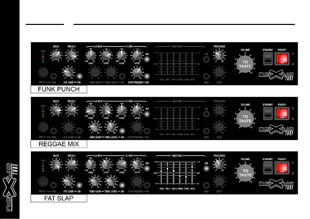
QUICK START SETTINGS - Suggestions only, experiment
OPERATING INSTRUCTIONS
Page 6 /24
Page 7
XN T
Laney
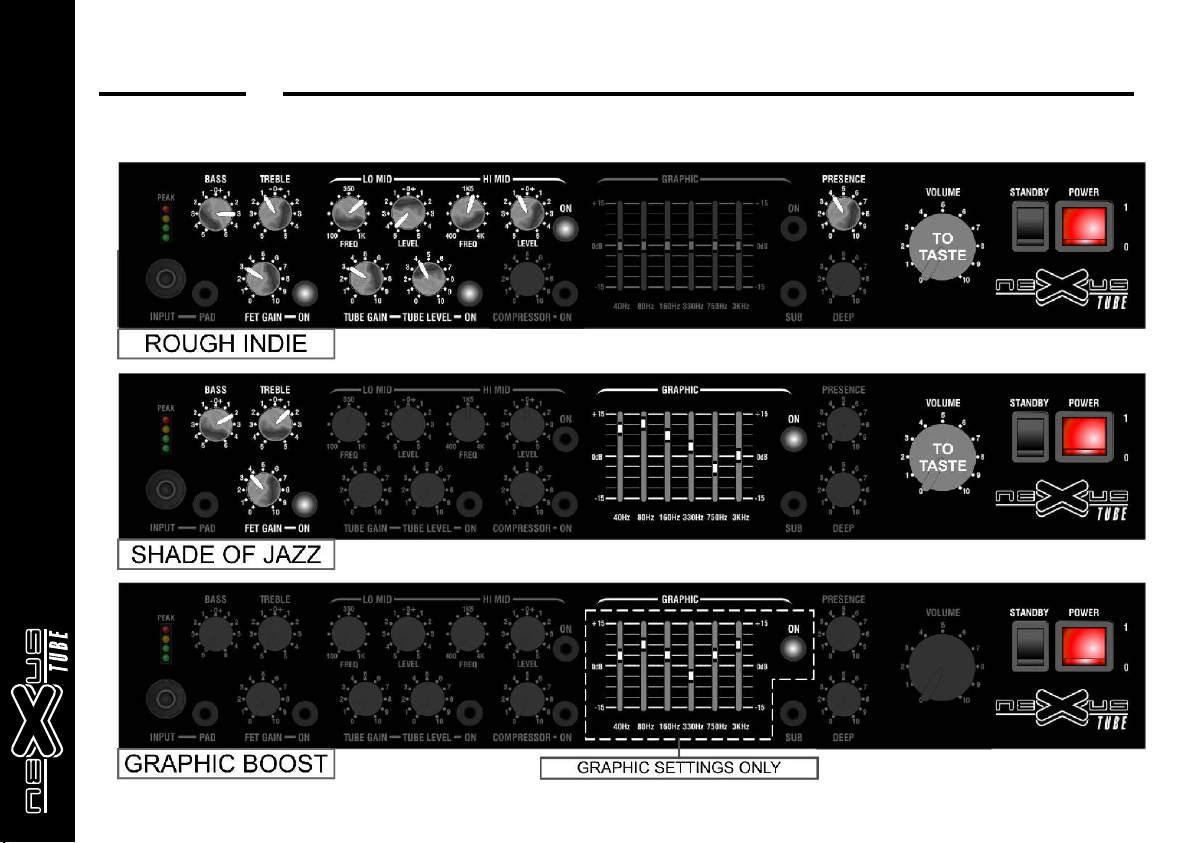
QUICK START SETTINGS - Suggestions only, experiment
OPERATING INSTRUCTIONS
Page 7 /24
Page 8
T
NX
Laney
FRONT & REAR PANEL CONTROLS
OPERATING INSTRUCTIONS
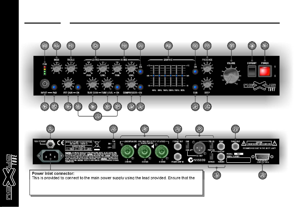
Power inlet connector:
This is provided to connect to the main power supply using the lead provided. Ensure that the
supply voltage is suitable for your amplifier as marked on the rear panel. Ensure that the
amplifier is connected to a grounded/earthed supply socket. Do not remove power supply
earth connections under any circumstances.
Page 8 /24
Page 9

T
NX
Laney
NEXUS NXT FRONT / REAR PANEL FEATURES
p
l
et
:
11
um ed
ill inat f
l
orr ly Thi
ay c ect
s
Bas
22
33
4/54/5
66
77
88
99
1010
1111
1212
1313
Con
z r det
a
ero cent
t
or ut to obt
e
T
rebl
Con r :
er
en e
o c
tr
t or c
boos
ut to obt
aram
P etri
m
frequenc es
both c
P etri
Graph c
P
des s
Po
mi
i o r
on
tr
aram
w
t
h) he
i S i e s:
o
an
verall
ired ound. T d LE
s
i
c
resence t
ired
l m
Co :
u
e
e
or
rectl
s el( ee input lev meter).
t
d
hould wit
w
t
if
ering
peak
w
er sw tch: U
ont i
rol s
nut
or
es
bef
p
J l n our
ut ack:
his
T
or m
ost of y ur
.
t o
s
r
l: Thi
e
c ai
t ol
ent
det
c i
M
d c ntro s:
band.
E
ac pair onsis
t
be cont ol
ol
s m
ay be wi d
c
i w
M
d s
s ch i
l
d r
eq a
E
q
swi
Con
r : B
o
er c
t z o the ontr
ound.
ntrol djusts he
y s ev on
et the input l
swi
h o
he n
bet
ween sets
.sers
i
et t
s o inimum a
t t s
e
urning
P
ug i
4 band
o pl
ay need
s
m adjusti if
c rol k s c nt wis t
ont boosts (cloc wi e) or uts (a
i on
ent
n your desired
s
c rol t
Thi
ont boos s (cloc wi e) or uts (
pos
ition where he sound
ai
n your desired sound.
o l
h c t of a r
s tched on an of
itch:
wit
s
he
i
T s
adjust. St rt wit all t c
he sli er
t
: hi
ch
T
ol oos s m equenc in
A
is ed o
This
ch on the
ru posit
et . wi c
pl ier
s
ed for
m
he
y
di play
ing. t
ay
pos
ti
of boos
T e
hes c
led ly T
independent
his w
T s i c t ns
i i
llum
nated oper ed.
l
x s
iders c rol v fr ncy bands to all
h
s t
D'
s
wit ns on he
s
s ch tur
t
the id to high fr ies t
ol f
has no ef
t s
ound
els
us
t turn and
am
pli
ion t a
and he mplif er is
c
thout using the power swit
after
t
urning on the ain pow
nd hat
t
andby s
t
a
here ing good
guit r us
how t
s
s
t
Adjus he ET
ng r s
e he
wher
t s
sound.
k s c
t is
ont
rols cons
f equency
.
f.
t
h ur
when
ont indi idual eque
he
ont
lum d t
ay
il inate
t Graphic sliders (il inat when press ) t is o c r
t
ec
. When
lev
ent
el
s
the dis
on
f
t c
ier wi h the swit
t
s i a
use i i a good
m
t S
andb
he
t y wit h is
t h o ode.
wi
c t
ev
s he l el of s
F n T
gai or ube
any
EQ cont
ound up s
is unchanged. When setting
unchanged. When
is
t of tw pairs;
l t
se ec
ow v c e
his
all s
on he
t two paramet
atfoots i c T
rols in the entr ze
even when he raphic inac ive.
s t n
et
t t
o he power plifier and peaker . Start
plhav c
ay.
o
he v
f
f t
h
i
r djus olum as req r
eady to go. A t the V
de
er
int
S
c
run m
a
quality
ion
ing up i
high ol
s he
et to t
OPERATING INSTRUCTIONS
ignal t
going through
Lev
ont
el c ro s
ar hangdisp
ol
e c ed.
iclock e)
ant w s t
iclock i e)
o
c
ol a
ontr
ery
ac urat m
band ric dr c ols a
c e
he
power am
t ly
i
ial
am s s h his
t t t
ages
here
h, t
o ur f
t
t
n of he st
o
he
t ampl ier. Befor
t
in the s
ll
This wi ass
c ac
s reened j k l nput s s both acti e
he
s ng nit
etti
t l
he eft hand c
and
boos
i
d
mi
ow
ro
detented posit o
g is
lum
ed ed
pl ier
t t
s
ar
he
applied o
standby posit
all t
by
owing an ins
t
andby s h
if e
andby pos ti
i t
in t
s
he pream fi . T ideal ev
l
(depen ng on w
l
ov l reque r
erall
o hi equen
he verall
up i ial
at
prolonging he fe of the ubes.
ead. I
ly
one ont
t and ut l
c
band
ont
ange ontr
ou o
y
t adjus our
i n
tdes
o s and
if , t
add brightne
t
z p dd enc as equired
ero
out
he put tubes.
i
A
on. f er tw m
e
witc f
wi
s
tching ens
i
o l
n. A
pli er
di
y yo l s (Regu arl
check
ow f
initially t
s
c ev control,
t
ant
low the am if t war
ncy
ar n
t i t
gh fr cy sounds
t
t
art in
he cent e i ion add
ng
rolli
the low mid re i
el h h
rol.
Us par
ing the
. (Can
t y
add
and
osition and a pres e
t n o
irs hi
uit v
s
I
als ont
wit
n der
o
i ut
n
T e c
ui ed.
ur
n
t
t
s
will then a
on
pl ier o
li t
m
s
t s
I
when wit hed b
ur
he l el
hi
h hannel u
c c you are sing) o
ur
evel and
sounds
f
om your
he ent i
c re posit on and s
r
r pos
f
wit bot bands
ametric
s
e
l o b
controlled r ot
s hi
ound. T
all
amounts of
ol re y
lable
edge to your sound
et
t z up l l
o
or to pr
s
v
pea
e s
kers are connec
and
e
m
c
d
oi
pas
es ensur
h swit h
wh m
is en the a ber l gh
adjust as required).
s
bas guit
f
t
quenc es and he
s
ero and turn
he
t V
any noises arr
m
om your
c
ol
ay also us t
bas guit
and s
hi
o ihigh id
t s allows tw m d
s c
an
t
on t
up t i
s v
oot
wit h or
i e b
remote f
em
us ul r ol
be
ef
an
boos d c
motel i
r
g
he f
li
e of your tu y
um
s
ol e i
be
ac
t
t
k o he run
i ing
t
ed, the V
in his condit
as
ses
i t i In ut evel m er
t
s he
et t
a
add m
s ar
al a oz
ml mounts f
t r
ely ia
v t
fo
ut
v
a he w
t
.
to obtai
s
ow
e
s t to minim
ed
v
.In
ont
r
. The c
o
all am unts
. It has
i d
ght han
sw
he
et . or
s
o's c
t o
o
btain
foots i
n ourWhen set
y
t Vo
y
af
er
bes
o of then s i c t t
turn
m ampl ier
ode.
When
ur pow down the am if
at yo
olum
wC
on for t o
Page 9 /24
i
tch
you
ums always s
f the
e
s
ol
r
has
a
he
t
yas
our
t
h.Graph
c
ou S an by tch:
Page 10

T
NX
Laney
1414
p
FET Gai :
1515
occasion lly
ing
adjus
t
FET Gai
1616
1717
1818
1919
2020
2121
2222
2323
2424
e footswit h.
o
t cre
m
Tube Ga n con rol
i t
ion wi be pr du
tor
di
t ll o
s
h added t the s
warm
t o
el nd pickin actio
le
v a g
Le el
v
hi he th G
g r e
Tube
ch nnel swi
a
m t
re o e footswit
r
ignal will
s
nction ca
This f
u
Compre
ch d i . I it i
wi
t e n f
s
es or s s
comp
r s i
re sof kn e
o t e
it u eful for balancin o t the sound l ve s a ro s t e
is s g u e l c s h
f i f
t e
o hfo tswitc .
Sub Swi ch
t m
uses
i
ated whe
n
o
some h
w
in
adjus
t
h: Pr ss in o r
it
S
c e t
w
d
djust n c nj
A i o
n
illu inating on the l ud st not s
m o e e
a
when he EQ co
t
switch: Th
n
ontrol:
c
contro
in
a
c
h.
functi
u
is onditi n
h c o
e out d
b r e
a so
n l
so cont ol:
s r r
n)
o
w
ompressi
c
nta
a
i
m
of t
switch:
r
s
T is wi ch
: h s t
t
p i
y e des rab
a b i
in thi
n
This cont
pend nt on
t d
e e
a
sm ll moun s t
a a t
u
s s
i
is
T
l n
h
:
ed. When set at
c
und. Set o around
o t
. Set t 7 10
n o -
This co trol adjusts t
is, the lower the
l
ch T is wi
t : h s
n: You c n
o a
e
b
This adjusts
t is im
I
h
to
o
s
on and off may
itche
d
nin a constant high level ou d
i g s n
e and. I m
h b t
Th s s
i
e t
l
m
s
o
du
e
wit the inpu level
ion
nc
h t
t
trols are
n
w
t
d
n
o
p t t
i t n
o
ables the FET
itch e
n
contro co trols t
n
ch
t
ut
m
led on y will be perman nt y il m
ed
he
l e l lu
r
irectly fro
ut ng bet e
d
m i w
perated by d
or an for co
gh he more co
n s a ded.
o i d
y be t
a
itch turns th
w
n pressed bypasse
h
e
w
s boo
s
ve the ex ra eel
h
a t f
de.
oillumi
sts from
ol dj
u
r a
type of spea
he
t
your esire
obtai
n d
y whe u ing high output bas
e he np t s
c t i u
djusted. (Re ularly check our le
a g y
h
ze
r
s extr
giv
e
h v r e b
Le el on rol
v c t
nable
s
e
y ur sound sent to the DI
e o
your ba s to the t
m s
e
selec
e
the amou
rect operation th
r
m
var
The co tro shoul b
n l d
rn d off r m
u e e
e s
t is ap lie
s p
a c
k
nsitiv
it n s
e
et r t n mi
m e o o
. This
play
ou
y
gain
moun of drive appl
e
a t
e t be stage op
o t
h u
-4 tube d stortio
3 i
m overdriven and sustained sound
e e
e olume level f om th tu e
the tube drive channe
guitar ch nges
n bas
s a
bo h c anne s remotely on the fo
ing
t h l
t
comp es ion applied t
t o
f r s
n
pression
c ns derabl . Set at z
y o i y
compres or
a
s
. This waste power and causes excessive sp
d
he
of
t
tight ontro
cabinets con
er
soun
d
wil give t
l
ch nn l.
a e
wil
l
u r n
a
wil oc
l
s
hi
c
w
tel
y
o
a f
ub onic f lter
s s i
s
xt eme low's. S in
e r o
ll
.
d
h
W
rat
e
co e m re
b
e m s o
n
d o be to m int
ne
e t a
an s
d
ne out o th
put le
e i
t t
n
h
if t
ur
,
c
used
e
on our g ita
trings
y u
particula ly use
h i
s r
the footswit h.
vi
a cup wi h the r st
on nd of . (Il
sound (zero os
ed
p
ec ed to
n t
OPERATING INSTRUCTIONS
itch is illuminated whe p essed in.
The s
es
s
al
n
n ope
e
ed o t e re
i t h p
s n it s c eanes
e i ' l
. When operated the switch is llumin
l i
nat
i
tc
e
o ow the less
o l n
ro he e i
e t r
to give more
that is
h l
ly
h
v s s
p
e
e
.This allows silent tuning a
v m t
l
t
um s nal le
e opti
m ig
el and adju t a
ated the swit h i
r c
dis
tage.
s
in
a
by d selec
er
ea
s e
k
n he evel mete .
d
o t l rchannel. In t
anel only
rear
p .Your
your ou
o s
el e er
very l
s
. T
r
ul i
f
es h n acti e).
umina
t w e v
us d t a oid extremel
e o v
thi case re
s p
tio
i
lif r. h n
he am
p ie W e
e disp ay
run t
wit
requ
s
e stage.
mp tu
b
a
low di
t
th a warm r t
inct w
i e
t
.
s
it in conju cti
et
n
S
the co rec le
r t
2929
tswitc
o
(The c
d.
n
tin a ou d t
er
s o
a g r n
p
i
ompressi
c
ttle ef
i e o
ain an tr ns
us
t d a
s
by avoidi g sud
er
e n
h
live stag s
n e
s t
s
) t a o e ope
n o m r
w n r In ut Pa
.
a ber li ht
th
e m g
h
throug the p ea
el
h r
v
ed .
ir )
ill mi at d.
s u n e
The
to tion m de
s r o
n
o
n
el
o
v
bo h the FET ch
ing
t
t
.
h
m re so
o p s
n ill
o w
f ct n
ou
y
en
i
ion
ua
t
it
It may
lo fr quen ies <3
y w e c
ak r cone m ve
e e o
wi ch o defe t t
e
s t t a
h
roun
n
up init ally st rt
ing
et
i a
t
s
in
illu
a d h
m
fie . This vel m
p
li r le
m
ls be operated by
t may
a o
I
the se tin th
higher
t g
just a small amount o
wit
h
ou d ha
icker
s n t
h
ith the in
w
he e er
t m t
e
h
es
r
soun
r
att
t
en
d
w er y u nee
s h e o
als b o
o e
d s
ut ev
p l
.
ted. It may a
a
a
switch m
r
m
a
lt.
u
ck to our soun . At lo
a y d
vo m incre ses. I
lu e a
u b i
er ight befor the c
b l e
ls the level w
A o s
. As the c nt
d o
erated by the re
p
e
n w f
m
ilte . T e swit h will
e
f r h c
h
ed ba s sou
in
te and t e red
more ov
e
respo
t
l meter
e
e perated by the
so
b o
l
nnel and
st e lluminated fo
ol
r
to ke
d
H ar iving at the
0 z r
t. Ho ever or
t 1 . Theeff
d
a 0
n
the zero po
igh
l
a
the
e r
tube
f
ds to laying
n p
. Gen ra y t
e ll
the Tu
bTune Mte
m resso
o p rcontrol to functi
en the
his
incre
a
is
er se tings
w tm
is lso
t a
p ou sound
e y ref ect ve or
e
o
tCompre so
m
tudio
sspeakers es ec ally when ba
iti
o
s
ju t
t s
ee
y
n d
rd ive
e
thi
r s
sed
e
b
ct
e
n and
e
hTube
s
iDeep Contr l:
Page 10 /24
Page 11

T
NX
Laney
Cut out: This is provided to protect the amplifier in place of a power fuse. In the unlikely event of it operating the button will protrude out
2525
farther than normal and can be re-set by pushing back in. It may take several seconds before it can be re-set. If it trips again check for
possible causes: damaged tubes wrong speaker connections etc. Should this not cure the problem refer to a qualified technician.
Fan Switch: This switch is used to turn off the cooling fan. Normally this should be left on at all times. However when in very quiet
2626
situations like studios the noise can be a problem in which case it can be turned off provided the amplifier is not used at full power for
prolonged periods. Always remember to turn it back on when out of the studio. The amplifier is designed with plenty of ventilation so
overheating is very unlikely unless the ventilation is obstructed. Should this happen the amplifier will automatically turn to standby mode and
not switch back on until it has cooled. Whilst waiting, check that the fan is turned on and the ventilation is not blocked. This will speed the
return to normal operating.
Speaker Connectors: There are three Speakon /Jack combination sockets provided one each rated at 2 Ohms, 4 Ohms and 8 Ohms
2727
total load impedance. Only one of the connectors should be used at any one time. (see speaker connection details) It is very important to
observe correct speaker matching and connection to avoid damage to your amplifier. Never operate the amplifier without speakers
connected. When using Speakon connectors they should be wired 1+ to the positive speaker terminal and 1- to the negative terminal 2+
and 2- are unused and not connected within the amplifier.
When using Jack leads ensure they are properly rated speaker cable and not instrument types. Jacks should be wired tip to + speaker
terminal and body to - speaker terminal. For long term reliability we recommend using Speakon connectors when ever possible.
Preamp out Power Amp in jacks: These jacks are primarily used to connect other power amplifiers or connect Nexus Tube amplifiers
2828
together to boost power outputs. When connecting to another power amplifier the preamplifier output jack should be used. The level at this
jack is nominally +13dBu or 3.4V at full power. The signal at this socket will be affected by all the controls on the preamplifier except the
Deep and Presence which will only operate on the power amplifier. When connecting two Nexus Tube amplifiers together to boost power
levels the master amplifier preamplifier out jack should be connected to the power amplifier input socket of the slave. The master will then
be in complete control of the slave power amplifier. (The Deep and Presence control will still work independently on both amplifiers).
DI output socket and switches: This socket is a balanced signal output for sending to mixing desks, PA etc. The signal may be sent from
2929
the preamplifier before any of the EQ controls or effects (Pre-Post switch set to Pre) or after the EQ and effects but prior to the Volume
control (Pre-Post switch set to Post). The nominal level is -20dBu or 100mV. A ground lift switch is provided to avoid any hum problems
there may be when connecting to a mixing desk/PA. (try it set in both positions to find the best performance).
Tuner Out Jack: This socket is normally used for connecting a tuner to allow continuous tuning of your guitar. When the amplifier is muted
3030
a signal is still present at this socket. The output level is similar to your guitar.
Effects Send Return Jacks & Bypass switch: These sockets are used for connecting external effects processors to your amplifier. The
3131
insertion point is after the onboard preamplifiers and EQ but prior to the Volume control. Use the send jack to connect to the input of your
processor and the return for the output. The loop is an insert type so all of your signal is routed via the external processor. So any blending
between direct and processed signals must be performed in the processor. When not using the Loop it is advisable to operate the Effect
bypass switch to avoid any reliability problems sometimes associated with jack connectors, even though gold jack sockets are used here for
increased reliability. The signal level is nominally -10dBu or 250mV.
Footswitch connector: This D type connector is used to connect the dedicated FS7 footswitch to the amplifier. Never use it for any other
3232
purpose as damage may result.
OPERATING INSTRUCTIONS
TM
TM
TM
Page 11 /24
Page 12

T
Cab Impedance No of Cabs Total Impedance
4 Ohm 1 4 Ohm
4 Ohm 2 2 Ohm
8 Ohm 1 8 Ohm
8 Ohm 2 4 Ohm
8 Ohm 4 2 Ohm
NX
Laney
NXT
NXT
CONNECTIONS
CONNECTIONS
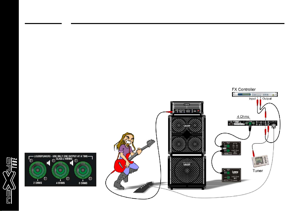
Speaker Cabinets:
The Laney Nexus range of cabinets has been specially designed for use
with this amplifier:
NX810 4 Ohm
NX410 8 Ohm
NX115 8 Ohm
Their power ratings and impedances have been carefully matched for
optimum performance. Use of other cabinets may result in an inferior sound.
(See connection diagrams for wiring up).
NEVER operate the amplifier without speakers connected.
OPERATING INSTRUCTIONS
4 Ohms
Mixer
Speaker cabinets should be Daisy-chained together so
that only one connector on the amplifier is used at
once.
Page 12 /24
Page 13
T
NX
Laney
Speaker Connectors:
There are three Speakon /Jack combination sockets provided one each rated at 2 Ohms, 4 Ohms and 8 Ohms total load
impedance. Only one of the connectors should be used at any one time. It is very important to observe correct speaker matching
and connection to avoid damage to your amplifier.
When using Speakon connectors they should be wired 1+ to the positive speaker terminal and 1- to the negative terminal 2+
and 2- are unused and not connected within the amplifier.
Make sure the impedance of your cabinets matches the
setting on your amplifier. Improper impedance matching will
result in reduced power output and compromised sound at
best and amplifier failure/premature tube failure at worst.
Laney recommend the use good quality loudspeaker leads
fitted with Speakon connectors, cheap leads are often not up
to the job of handling the large requirements for loudspeakers
and can often short out, or go open circuit. Tube amps don't
like running into an open circuit.
Speakon Connectors on Rear Panel
(Use either:
1/4 Mono Jack or NL4 Speakon Connector)
TM
TM
TM
TM
TM
OPERATING INSTRUCTIONS
Page 13 /24
Page 14

T
NX
Laney
TECHNICAL SPECIFICATIONS
Power Amplifier: 400W RMS @ 5%THD into 2/4/8 Ohms
Power Consumption: 800 Watts maximum
Size: W*H*D, V = 524*218*400, 45ltrs
Weight: 34.5kg
Inputs: Single Jack with -10dB Pad switch. Zin 1M Ohm 20mV-8Vrms
Preamp Bar Graph Level Indicator: 4 led bargraph display with
Fet Gain control: With on/off switch and LED indication (Remote
Tube Drive control: 40mV to 850uV sensitivity.
Tube Master control: With on/off switch and LED indication.
Compressor: Single control for threshold and range with auto
Bass & Treble: Shelving controls. ( ±12dB@50Hz, ±15dB@5Khz)
Dual Para-mid: High and low paramid EQ (±12dB 50Hz-600Hz &
Graphic EQ: 6 band (+-15dB @ 40Hz HiQ, 80Hz HiQ, 160Hz HiQ,
Presence Control: Active power stage HF feedback control
Deep Control: Active power stage LF feedback control.(+5dB@50Hz)
Sub Filter: Active filter prior to output stage (-3dB @ 35Hz 24dB/oct)
Master Volume Control: Residual noise -60dBu Volume min, -42dBu
Power & Standby switches: Relay controlled standby on both HT
(3xECC83,1x12BH7, 8xKT88) Small signal parameters
20Hz-20kHz -1dB, THD typical 0.25%
combined mute indicator and peak lights.
footswitchable)
(Remote footswitchable)
level adjust.
Sited post gain pre-EQ
(Remote footswitchable)
±12dB 400Hz-4kHz)
On/off switch & LED indication.
(Remote footswitchable)
400Hz LoQ, 800Hz LoQ, 4kHz LoQ)
On/off switch and LED indication.
(Remote footswitchable)
(+10dB@3kHz)
Switchable with LED indication
Volume max. (Typical SNR 85dB)
rails to power stage. All signal switching via sealed gold
contact relays only.
OPERATING INSTRUCTIONS
Speaker outputs:
3x Neutrik Combi Speakons Jack/Speakon. 2,4,8 Ohms
Preamp Out Power Amp In:
2x Jacks post master volume (+13dBu/ 3.4V)
Power amp nominal gain 24dB
DI out:
Male XLR socket
Balanced & switchable Pre-Post EQ. (-20dBu)
Ground Lift switch feature.
FX Loop:
Send return Jacks (Insert) post EQ pre Master volume.
Nominal 250mV (-10dBu)
Tuner Out:
Jack feed from input buffer Pre all controls. Still operative
in mute mode.
(Muting via de-selection of both tube and FET channels)
Tube performance indicators:
Individual tube sensing circuitry giving indication at each
tube base via led's for performance levels and bias.
Individual output tube fuses with LED indicators to
prevent the amplifier failing due to a single tube fault
during performances.
Fan Control:
On/ff switch for cooling fan.
Overload cut out:
Re-settable overload power button in lieu of power fuse
for increased reliablity.
Remote switching:
Via the 5 way included FS7 model footswitch,
Tube channel on/off
Fet channel on/off
Paramid on/off
Graphic on/off
Compressor on/off
Muting via de-selection of both tube and FET channels
(All settings memorised at switch off)
TM
Page 14 /24
Page 15

T
NX
Laney
OPERATING INSTRUCTIONS
BLOCK DIAGRAM
SUB BYPASS
HP FILTER
3
1-
1+
1-
1+
1-
1+
PAD
ON
TUBE BUFFER
VOLUME
MUTE
SUBSONIC
HP FILTER
FET CHANNEL
FET GAIN
TUBE
CHANNEL
TUBE GAIN
COMPRESSOR
ON
ON
ON
TUBE VOLUME
COMPRESSOR
TUBE OUTPUT
DRIVER STAGE
BASS/TREBLE DUAL PARAMID
PARAMID
ON
TUBE OUTPUT STAGE
8*KT88
DEEP
PRESENCE
GRAPHIC EQ
ON
6 BAND GRAPHIC
This product conforms to the requirements of the following European Regulations, Directives & Rules: CE Mark (93/68/EEC), Low Voltage (72/23/EEC), EMC (93/68/EEC),
RoHS (EU2002/95/EC), WEEE (EU2002/96/EC)
In order to reduce environmental damage, at the end of its useful life, this product must not be disposed of along with normal
household waste to landfill sites. It must be taken to an approved recycling centre according to the recommendations of the WEEE
(Waste Electrical and Electronic Equipment) directive applicable in your country.
Trademarks: Speakon and the names of Neutrik®AG products referenced herein are either trademarks and/or service marks of Neutrik®AG.
TM
MUTE
ON
SUB
12
Page 15 /24
Page 16

T
NX
Laney
TROUBLESHOOTING DIAGRAM
No Sound or Bad Sound
Instrument/Cabinet Not
connected correctly
No Power Illumination
Mute LED On
Tube Status LED's
One or More On
No Signal Present
OPERATING INSTRUCTIONS
Connect instrument or cabinet correctly, Retry
Check AC Power cord connected correctly,
Check AC Power cord plug fuse has not blown,
Check Thermal Trip on rear panel, Retry
Enable a channel, Retry
Check Tubes
Check tube fuses, Retry
Input Level Meter Peaks
Easily
If the problem is not covered above, or the steps lead you here, then contact
your Laney dealer who can help with servicing or information.
Reduce input gain, enable Pad, reduce excessive
Boost, Retry
Page 16 /24
Page 17

T
NX
Laney
TUBE STATUS INDICATORS / FUSES
V1V1 V2V2
V3V3 V4V4 V5V5 V6V6
V7V7 V8V8 V10V10V9V9
Each of the eight output tubes have two led indicators along side them; one Blue and one Red.These are there to indicate the
status of the individual output tubes.
When turning the amplifier on in standby mode the red leds will all show immediately.
After two minutes turn the standby to run (with speakers connected but no signal) the red lights will gradually go out and there
should be no lights showing.
When a signal is applied the blue and red lights will flash in sympathy with the sound.Each tube also has it's own fuse this is
provided to help prevent amplifier shut down in the unlikely event of a tube failing during a performance.
Fault conditions: If a red light remains on after the amplifier goes into run mode without a signal present then the associated
tube may have failed or its adjacent fuse may have blown. Check the fuse and replace with one of the same type & rating. If it
blows again then the tube is suspect and should be replaced with the same type and grade number. If the blue and red light fail
to come on, with a signal present, by a particular tube or tubes then those tubes may have failed and should be replaced with
the same type and grade number. (Don't forget to also check their fuses).
Re-biasing and trimming should only be carried out by qualified service agents who have access to the Laney service manual
data for this product.
OPERATING INSTRUCTIONS
TUBE DEFINITIONS
V1 Preamp Tube Channel
V2 Output Buffer
V3-V10 Output Tubes
V11 Phase Splitter Tube
V11V11
V12 Driver Tube
V12V12
Available from Laney through your dealer.
ECC83 Hi Grade
Pt No. 005570
ECC83 Hi Grade
Pt No. 005570
KT88
Pt No. 007318
12AX7
Pt No. 007320
12BH7
Pt No. 007319
Page 17 /24
Page 18

T
NX
Laney
Care and replacement of Tubes:
Tube amplifiers generally sound much warmer/sweeter than solid state transistor amplifiers but they also need a little more respect due to the fragile
glass tubes themselves. The NXT uses top quality Tubes, two ECC83 preamp tubes, a 12AX7 Phase Splitter Tube and a 12BH7 Tube to drive the
matched set of eight KT88 Output Tubes which should give you years of trouble free service, however like all tube amps; it is important to treat it with
a certain amount of care.Take care when moving the amplifier.
Tubes are fragile glass components; they can easily be damaged if thrown in and out of vehicles.
Allow the amplifier to warm up to room temperature before switching it on. The sudden thermal shock generated can crack the cold glass tube
housing plus any moisture is bad news around high voltage electronics.
Allow the amplifier to cool down after playing before moving. Hot tubes are more susceptible to damage than cool ones.
A tubes life expectancy is based upon a number of factors which include operating temperature, how hard and how often it is played, vibration due to
travel etc. Tubes should be changed in your amplifier if you notice any change in your amplifiers performance etc. They need not be changed at any
regular interval.
Typical problems with preamp tubes can be; a crackley noise, hiss, hum and microphony.
Typical output tube problems can be sound lacking in punch, sound lacks extreme highs or lows and low level hum. The Output tubes can be
replaced singularly if you replace them with the exact same type AND grade as factory fitted otherwise they should be replaced as a matched
set. Exact replacement preamp tubes and matched sets of output tubes are available from Laney via your dealer.
To change a tube:
Switch off the unit and unplug from the mains supply. Wait for the tubes to cool down. Access to the tubes on the rear chassis can be gained by the
removal of the rear grill (8), by unscrewing the four 15mm screws (7) securing it in place. Unclip the spring retainers from the Phase Splitter and
Drive tubes, they can then be gently pulled out from their sockets. Take care when pushing in the new tube to make sure that the pins are all aligned.
The output tubes have a spring retainer fitted the tube socket which grips the base of the tube. The tube must be released from this by pushing the
retaining clips down with one hand, whilst gently rocking and pulling the tube from its socket with the other. Some of the outer row of tubes may need
to be removed to gain access to the tubes on the inner row. Take care when pushing the replacement tube past the retaining clips to ensure that the
rib on the base of the tube is aligned in its locating slot in the socket.
The chassis need to be removed from its wooden sleeve to allow changing of the Pre-Amp tubes, with reference to the diagrams, this is easily
achieved by:
1. Removing the two side handles (5) by unscrewing the six No 8x1" (3) & four M5x30mm (2) on each handle. Remove the metal bar away from
the handle and then gently pull the plastic body out of its recess.
2. Remove the rear grill (8) by unscrewing the four 15mm screws (7) securing it in place.
3. Remove the four M6x30mm bolts (6) and finishing washers (4) from the front of the unit.
4. Finally remove the six M5x30mm screws (2) from the base of the cabinet. You should now be able to slide the amplifier forward freely. Be
careful as the unit is very heavy.
The Pre-Amp tubes can now be removed by unclipping the retaining clips and gently pulling them from their sockets. Take care when fitting the
replacment tubes and ensure that the pins are all aligned properly. Refit the retaining clips.
The chassis is refitted by reversing the removal instructions.
OPERATING INSTRUCTIONS
Page 18 /24
Page 19

T
NX
Laney
Refer to Labels for tube ID & Grade etc
OPERATING INSTRUCTIONS
1. NXT Chassis Assembly
2. M5 x 35 Csk Rsd Posi (Pointed tip) Pt No.10260
3. No8 x 30 Csk Posi Screw Pt No.007194
4. M6 x 30 Button Head Socket Screw Pt No.007287
5. Bar Handle Steel/Plastic 90 top Pt No.007262
6. M6 Finishing Bush Pt No. 007286
7. 15mm Posi Pan Screw Pt No.007197
8. NXT Rear Grill Pt No.007285
5
1
KEY
0
8
5
Page 19 /24
Page 20

T
NX
Laney
USER SETTINGS - Store your own cool sounds
OPERATING INSTRUCTIONS
Page 20 /24
Page 21

T
NX
Laney
USER SETTINGS - Store your own cool sounds
OPERATING INSTRUCTIONS
Page 21 /24
Page 22

NXT
Laney
OPERATING INSTRUCTIONS
FRONT & REAR PANEL SPARE PARTS - Available from Laney via your Dealer
004075 Pot
004099 Pot
004099 Pot
005127 Bkt
004099 Pot
004075 Pot
004099 Pot
007304 Slider PCB Complete
004099 Pot
005127 Bkt
007303 Vol PCB Complete
530027
230V
007305
100/120V
007435
Thermal Release
004426 5A (230V)
005325 10A (100/115V)
Filtered Mains Inlet
005319 3A (230V)
005323 6A (100/115V)
007376 Speakon
Connector - (3 off)
007372 Non-Latching Push Sw. (3 off)
004071 Pot
007372 Non-Latching Push Sw.
004062 Pot
004062 Pot
007372 Non-Latching Push Sw.
TM
007309 14mm Dia Round Knob - (12 off)
007310 28mm Dia Round Knob - (1 off)
007299 Tube Preamp PCB Complete
007300 Input Preamp PCB Complete
004061 Pot
007371 Latching Push Sw.
005097 Phone Jack
004071 Pot
005127 Bkt
007371 Latching Push Sw.
007375 Male XLR
Connector
007373 Vertical
Slide Switch - (4 off)
007374 6.3 Vertical
Phone Jack (5 off)
007315 NXT Footswitch
PCB
Page 22 /24
Page 23

T
NX
Laney
PERSONAL NOTES:
OPERATING INSTRUCTIONS
Page 23 /24
Page 24

Laney
POWER TO THE MUSIC
L A N E Y A M P L I F I C A T I O N
w w w. l a n e y. c o . u k
In the interest of continued product development, Laney reserves the right to amend product specification without prior notification.
 Loading...