

Page 1

Laney
MXD120H,
MXD120,
MXD120 Twin
USER MANUAL
Page 2
IMPORTANT SAFETY INSTRUCTIONS
WARNING: When using electric products, basic cautions should always be followed, including the following.
1. Read all safety and operating instructions before using this product
2. All safety and operating instructions should be retained for future reference
3. Obey all cautions in the Operating instructions and on the back of the unit
4. All operating instructions should be followed
5. This product should not be used near water, i.e. a bathtub, sink, swimming pool, wet basement, etc.
6. This product should be located so that its position does not interfere with its proper ventilation. It should not be placed
flat against a wall or placed in a built up enclosure that will impede the flow of cooling air.
7. This product should not be placed near a source of heat such as stove, radiator, or another heat producing amplifier.
8. Connect only to a power supply of the type marker on the unit adjacent to the power supply cord.
9. Never break off the ground pin on a power supply cord.
10. Power supply cords should always be handled carefully. Never walk or place equipment on power supply cords.
Periodically check cords for cuts or signs of stress, especially at the plug and the point where the chord exits the unit.
11. The power supply cord should be unplugged when the unit is to be unused for long periods of time.
12. If this product is to be mounted in an equipment rack, rear support should be provided.
13. Metal parts can be cleaned with a damp cloth. The vinyl covering used on some units can be cleaned with a damp
cloth or ammonia based household cleaner if necessary. Disconnect the unit from the power supply before cleaning.
14. Care should be taken so that objects do not fall and liquids are not spilled into the unit through any ventilation holes or
openings.
15. A qualified service technician should check the unit if:
The power cord has been damaged
Anything has fallen or spilled into the unit
The unit does not appear to operate correctly
The unit has been dropped or the enclosure damaged.
16. The user should not attempt to service the equipment. All service work is done by a qualified service technician.
17. Exposure to extremely high noise levels may cause a permanent hearing gloss. Individuals very considerably in
susceptibility to noise induced hearing loss, but nearly everyone will lose some hearing if exposed to sufficiently intense
noise for a sufficient time. The U.S. Government's Occupational Safety and Health Administration (OSHA) has
specified the following permissible noise level exposure.
Duration Per Day In Hours Sound Level dBA, slow response
8 90
6 92
4 95
3 97
2 100
1 ½ 102
1 105
½ 110
¼ or less 115
According to OSHA, any exposure in excess of the above permissible limits could result in some hearing loss. Ear plugs or
protectors in the ear canals or over the ears must be worn when operating this amplification system in order to prevent a
permanent hearing loss if exposure exceeds the limits set forth above. To ensure against potentially dangerous exposure to
high sound pressure levels it is recommended that all persons exposed to equipment capable of producing high sound
pressure levels such as this amplification system be protected by hearing protectors while this unit is in operation.
SAVE THESE INSTRUCTIONS
WARNING: To prevernt electrical shock or fire hazard, do not expose this appliance to rain or moisture. Before using this
appliance, read the operating guide for further warnings.
Caution: Risk of electrical shock - DO NOT OPEN!
Caution: To reduce the risk of electrical shock, do not remove cover. No user servicable parts inside. Refer servicing to
qualified service personnel.
Intended to alert the user to the presence of uninstalled "dangerous voltage" within the product's enclosure
that may be of sufficient magnitude to constitute a risk of electric shock to persons.
Intended to alert the user of the presence of important operating and maintenance (servicing) instructions in
the literature accompanying the product.
This apparatus must be earthed.
EMC warning
It is inherent in the design of a loudspeaker and in the design of guitar pickups that they should emit or be affected by electro magnetic fields. Loudspeaker enclosures should not
be used less than two meters away from equipment, which is likely to be affected by electro magnetic interference.
Likewise, guitar fitted with electro magnetic pickups should not be used less than two meters away from any source of emissions such as loudspeakers. Emissions from
loudspeakers are dependent on the frequency characteristics of the drive unit. Levels were measured direct from the driver of 30 dBuV. These levels are reduced to a safe level at
a distance of 1,27 meters from the drivers.
Page 3
Care of your Laney amplifier will prolong it's life.....and yours!.
After unpacking your amplifier check that it is factory fitted with a three pin 'grounded' (or earthed) plug.
Before plugging into the power supply ensure you are connecting to a grounded earth outlet.
If you should wish to change the factory fitted plug yourself, ensure that the wiring convention applicable to
the country where the amplifier is to be used is strictly conformed to. As an example in the United Kingdom
the cable colour code for connections are as follows.
EARTH OR GROUND - GREEN/YELLOW
NEUTRAL - BLUE
LIVE - BROWN
Congratulations on your decision to purchase a Laney amplifier.
Laney products are designed with ease of operation as a primary objective, however to ensure you
derive the best from your new amplifier, it is important you take time to read this user manual and to
familiarise yourself with the control functions and facilities available
INTRODUCTION
BEFORE
SWITCHING ON
This manual has been written for easy access of information. The front and rear panels of each unit
are graphically illustrated, with each control and feature numbered. For a description of the function of
each control feature, simply check the number with the explanations adjacent to each panel.
Your Laney amplifier has undergone a thorough two stage, pre-delivery inspection, involving actual
play testing, as well as burn in.
When you first receive your Laney amp, follow these simple procedures:
(I) Ensure that the amplifier is set at the correct voltage for the country it is to be used in.
(ii) Connect your instrument with a high quality instrument cable. Use of cheap cables will compromise
the sound of your instrument and your amplifier.
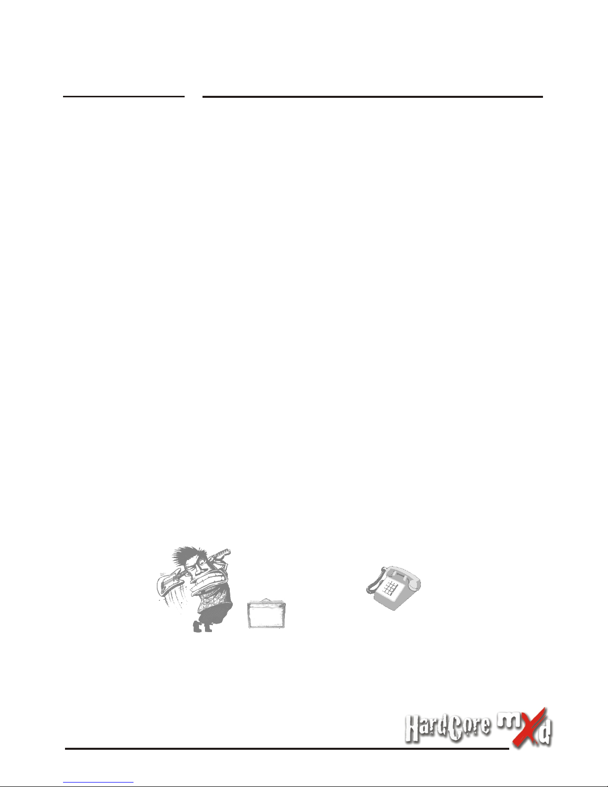
If there is a problem with your Laney amplifier
DON'T
DO
PHONE YOUR DEALER!
Laney
1
Page 4

MXD120H Front Panel
3
1
4
2
3
1
4
9
10 12
2
5 6
7
8
EffectEffect
Laney
2
33
66
55
44
66
55
44
101000 1010
22
88
99
11
77
33
00
11
22
On!On!
66
55
44
88
99
77
101000
22
11
33
00
11
PowerPower
Line
Out
Switch
Foot
CD / Line In
Level
Treble Treble
Mid Mid
Equalization Equalization
Bass Bass
Max
Volume
Master
Factor
Crunch
Volume
Clean
99
77
88
55 55
44 44
66
66
55
55
44 44
66 66
44 44
55 55
66 6666
44
55
00 001010 101000 00101000 1010 101000 001010 1010
22 22
88
88
11 11
99 99
33 33
77
77
33 33
11 11
22 22
88 88
99 99
77 77
88 88
22
11
99 99
33
77 77
11
11
33 33
22
22
Input
Dsp FxDsp Fx
88
99
77
Effect
Rotary
Delay
Chorus
Octave
Off
Dly + Ch
Rev + Ch
Flange
1
3
2
4
1
2
Reverb
1
2
11
2
1
2
120H120H
13 14 15 1711 1816
POWER SWITCH:
LINE OUT:
FOOTSWITCH: Socket for connection of FS2 footswitch allowing remote switching of
X-Factor effects and channel status.
CD/LINE INPUT: Sockets for connection of external CD player.
DIGITAL X FACTOR EFFECTS: Selects one of the fifteen onboard effects.
The MXD range of amplifiers carry the following effects:
EFFECTS LEVEL: Sets the overall level of the effect selected. The level control should
be used to get the desired blend between the “DRY” signal - no effect and the “WET”
signal - with effects..
TREBLE: Controls the high frequency EQ in the pre amplifier.
MIDDLE: Controls the mid frequency EQ in the pre amplifier.
BASS: Controls the low frequency EQ in the pre amplifier.
MAX BUTTON: Engages the MAX feature. This provides a scooped EQ boost to the
signal giving the amplifier a very unique distortion tone......try it out!
MASTER VOLUME: Controls the overall listening level of the overdrive channel.
Socket for connecting to an additional amplifier or PA system should more
power be required. The output of this socket should be connected to a line level
compatible input on the additional amplifier - such as an effects return socket, or when
using a mixing desk - directly into the line input on the channel strip.
Chorus 1 X Factor Chorus - Lush slow deep wave pattern
Chorus 2 X Factor Ultra Chorus - fast Shallow wave pattern
Chorus + Delay X Factor Ultra Chorus +300 ms delay
Delay 1 X Factor Delay 1 250ms "Slap Back" delay
Delay 2 X Factor Delay 2 400 ms short decay
Delay 3 X Factor Delay 3 500ms delay with medium decay
Delay 4 X Factor Delay 4 600ms delay with long decay
Flange 1 X Factor Flange
Flange 2 X Factor Flange plus 400ms delay
Octave 1 X Factor Octave - low octave doubler
Octave 2 X Factor Octave plus 500ms delay
Reverb + Chorus X Factor Room reverb plus ultra chorus
Reverb 1 X Factor Room room-sized simulation reverb
Reverb 2 X Factor Hall large-sized hall simulation reverb
Rotary X Factor Rotary vintage rotary speaker simulator.
5
6
7
11
8
9
10
Page 5

20
3
1
4
9
10 12
2
5 6
7
8
EffectEffect
Laney
3
33
66
55
44
66
55
44
101000 1010
22
88
99
11
77
33
00
11
22
On!On!
66
55
44
88
99
77
101000
22
11
33
00
11
PowerPower
Line
Out
Switch
Foot
CD / Line In
Level
Treble Treble
Mid Mid
Equalization Equalization
Bass Bass
Max
Volume
Master
Factor
Crunch
Volume
Clean
99
77
88
55 55
44 44
66
66
55
55
44 44
66 66
44 44
55 55
66 6666
44
55
00 001010 101000 00101000 1010 101000 001010 1010
22 22
88
88
11 11
99 99
33 33
77
77
33 33
11 11
22 22
88 88
99 99
77 77
88 88
22
11
99 99
33
77 77
11
11
33 33
22
22
Input
Dsp FxDsp Fx
88
99
77
Effect
Rotary
Delay
Chorus
Octave
Off
Dly + Ch
Rev + Ch
Flange
1
3
2
4
1
2
Reverb
1
2
11
2
1
2
120H120H
13 14 15
20
11
21
19
FX LOOP: Send and return sockets provided for connecting external effects devices.
The FX SEND should be connected to the input of the effects device, the output of the
effects device should be connected to the FX RETRUN socket
EXTERNAL LOUDSPEAKER SOCKETS: Sockets provided for the connection of
speaker cabinets. Please ensure that the impedance of each cabinet connected is no
lower than 8 Ohms, The unit is designed to give it's maximum output when loaded with a
total impedance of no lower than 4 Ohms, which is easily achieved by connecting two 8
Ohm cabinets.
POWER SOCKET: Socket for connecting mains power. Please note that the mains
power fuse is also located here. Replace only with same type and rating.
FX Return
FX Send
Loudspeakers
4 OHM TOTAL MINIMUM IMPEDANCE
REFER TO USER MANUAL
FOR LOUDSPEAKER CONNECTIONS
Designed in the UK by BLT Industries LTD.
CAUTION
RISK OF ELECTRIC SHOCK DO NOT OPEN
SERIAL
NUMBER
Made in China
Fabrique en Chine
~100V AC 50/60Hz
Model
Power Source
Primary Fuse
~230V AC 50/60Hz
~120V AC 50/60Hz ~240V AC 50/60Hz
T5A L / 125V T2A L / 250V
MXD120H
WARNING - THIS EQUIPMENT MUST BE EARTHED.
WARNING - TO REDUCE THE RISK OF FIRE OR ELECTRIC SHOCK DO NOT EXPOSE THIS APPLIANCE TO RAIN OR MOISTURE.
CAUTION - TO REDUCE THE RISK OF ELECTRIC SHOCK DO NOT REMOVE COVERS.NO USER SERVICEABLE PARTS INSIDE.
REFER SERVICING TO QUALIFIED PERSONNEL ONLY.
ATTENTION - REMPLACER LE FUSIBLE SEULEMENT PAR LE MEME TYPE ET LE MEME CALIBRE.
ATTENTION - DEBRANCHER LE CORDON D’ALIMENTATION AVANT TOUTE INTERVENTION.
AVIS - RISQUE DE CHOC ELECTRIQUE - NE PAS OUVRIR.
CAUTION - FOR CONTINUED PROTECTION AGAINST RISK OF FIRE REPLACE ONLY WITH SAME TYPE AND RATED FUSE.
MXD120H Rear Panel
MXD120H Front Panel
CRUNCH FACTOR: Sets the level of distortion within the crunch channel.
CRUNCH FACTOR ON!: Engages the CRUNCH channel
TREBLE: Controls the high frequency EQ in the preamplifier.
MIDDLE: Controls the mid frequency EQ in the preamplifier.
BASS: Controls the low frequency EQ in the preamplifier.
CLEAN VOLUME: Sets the overall listening level of the clean channel.
GUITAR INPUT: Socket provided for connecting electric guitar.
18
12
13
14
15
16
17
17 1816
21
19
Page 6

3
1
4
9
10
12
2
5 6
7
8
EffectEffect
Laney
4
13
14
15
11
MXD120/120 Twin Front Panel
17
18
16
GUITAR INPUT: Socket provided for connecting electric guitar.
CLEAN VOLUME: Sets the overall listening level of the clean channel.
BASS: Controls the low frequency EQ in the preamplifier.
MIDDLE: Controls the mid frequency EQ in the preamplifier.
TREBLE: Controls the high frequency EQ in the preamplifier.
CRUNCH FACTOR ON!: Engages the CRUNCH channel
CRUNCH FACTOR: Sets the level of distortion within the crunch channel.
MASTER VOLUME: Controls the overall listening level of the overdrive channel.
MAX BUTTON: Engages the MAX feature. This provides a scooped EQ boost to the
signal giving the amplifier a very unique distortion tone......try it out!
BASS: Controls the low frequency EQ in the pre amplifier.
MIDDLE: Controls the mid frequency EQ in the pre amplifier.
TREBLE: Controls the high frequency EQ in the pre amplifier.
EFFECTS LEVEL: Sets the overall level of the effect selected. The level control should
be used to get the desired blend between the “DRY” signal - no effect and the “WET”
signal - with effects..
DIGITAL X FACTOR EFFECTS: Selects one of the fifteen onboard effects.
The MXD range of amplifiers carry the following effects:
Chorus 1 X Factor Chorus - Lush slow deep wave pattern
Chorus 2 X Factor Ultra Chorus - fast Shallow wave pattern
Chorus + Delay X Factor Ultra Chorus +300 ms delay
Delay 1 X Factor Delay 1 250ms "Slap Back" delay
Delay 2 X Factor Delay 2 400 ms short decay
Delay 3 X Factor Delay 3 500ms delay with medium decay
Delay 4 X Factor Delay 4 600ms delay with long decay
Flange 1 X Factor Flange
Flange 2 X Factor Flange plus 400ms delay
Octave 1 X Factor Octave - low octave doubler
Octave 2 X Factor Octave plus 500ms delay
Reverb + Chorus X Factor Room reverb plus ultra chorus
Reverb 1 X Factor Room room-sized simulation reverb
Reverb 2 X Factor Hall large-sized hall simulation reverb
Rotary X Factor Rotary vintage rotary speaker simulator.
3
1
4
2
5
6
7
11
8
9
10
12
13
14
Page 7

3
1
4
9
10
12
2
5 6
7
8
EffectEffect
Laney
5
13
14
15
11
MXD120/120 Twin Rear Panel
17
18
16
CD/LINE INPUT: Sockets for connection of external CD player.
FOOTSWITCH: Socket for connection of FS2 footswitch allowing remote switching of
X-Factor effects and channel status.
LINE OUT:
POWER SWITCH:
Socket for connecting to an additional amplifier or PA system should more
power be required. The output of this socket should be connected to a line level
compatible input on the additional amplifier - such as an effects return socket, or when
using a mixing desk - directly into the line input on the channel strip.
15
16
17
18
FX Return
FX Send
Extension Loudspeaker
8 OHM MINIMUM IMPEDANCE
REFER TO USER MANUAL
FOR LOUDSPEAKER CONNECTIONS
Designed in the UK by BLT Industries LTD.
CAUTION
RISK OF ELECTRIC SHOCK DO NOT OPEN
SERIAL
NUMBER
Made in China
Fabrique en Chine
~100V AC 50/60Hz
Model
Power Source
Primary Fuse
~230V AC 50/60Hz
~120V AC 50/60Hz ~240V AC 50/60Hz
T5A L / 125V T2A L / 250V
MXD120
WARNING - THIS EQUIPMENT MUST BE EARTHED.
WARNING - TO REDUCE THE RISK OF FIRE OR ELECTRIC SHOCK DO NOT EXPOSE THIS APPLIANCE TO RAIN OR MOISTURE.
CAUTION - TO REDUCE THE RISK OF ELECTRIC SHOCK DO NOT REMOVE COVERS.NO USER SERVICEABLE PARTS INSIDE.
REFER SERVICING TO QUALIFIED PERSONNEL ONLY.
ATTENTION - REMPLACER LE FUSIBLE SEULEMENT PAR LE MEME TYPE ET LE MEME CALIBRE.
ATTENTION - DEBRANCHER LE CORDON D’ALIMENTATION AVANT TOUTE INTERVENTION.
AVIS - RISQUE DE CHOC ELECTRIQUE - NE PAS OUVRIR.
CAUTION - FOR CONTINUED PROTECTION AGAINST RISK OF FIRE REPLACE ONLY WITH SAME TYPE AND RATED FUSE.
MXD120/120 Twin Front Panel
POWER SOCKET: Socket for connecting mains power. Please note that the mains
power fuse is also located here. Replace only with same type and rating.
EXTERNAL LOUDSPEAKER SOCKETS: Socket provided for connecting an additional
external speaker cabinet. Please ensure that the total impedance of the cabinet is no
lower than 8 Ohms.
FX LOOP: Send and return sockets provided for connecting external effects devices.
The FX SEND should be connected to the input of the effects device, the output of the
20
21
19
Page 8

In the interest of continuing product development BLT Industries reserves the right to change specification without prior notice.
BLT Industries LTD.,
Newlyn Road
Cradley Heath
West Midlands
B64 6BE
Tel: (00 44) (0)1384 633821
Fax: (00 44) (0)1384 639186
Web Site http:/www.laney.co.uk
 Loading...