


Laney
Series Mixer Amps
MODEL :
CD480M
CD516M
CD630M
C
oncep
t s
e
r
i
e
s
USER MANUAL
Version 1.1

SAVE THESE INSTRUCTIONS
WARNING: To prevernt electrical shock or fire hazard, do not expose this appliance to rain or moisture. Before using this
appliance, read the operating guide for further warnings.
Caution: Risk of electrical shock - DO NOT OPEN!
Caution: To reduce the risk of electrical shock, do not remove cover. No user servicable parts inside. Refer servicing to
qualified service personnel.
Intended to alert the user to the presence of uninstalled "dangerous voltage" within the product's enclosure
that may be of sufficient magnitude to constitute a risk of electric shock to persons.
Intended to alert the user of the presence of important operating and maintenance (servicing) instructions in
the literature accompanying the product.
This apparatus must be earthed.
EMC warning
It is inherent in the design of a loudspeaker and in the design of guitar pickups that they should emit or be affected by electro magnetic fields. Loudspeaker enclosures should not
be used less than two meters away from equipment, which is likely to be affected by electro magnetic interference.
Likewise, guitar fitted with electro magnetic pickups should not be used less than two meters away from any source of emissions such as loudspeakers. Emissions from
loudspeakers are dependent on the frequency characteristics of the drive unit. Levels were measured direct from the driver of 30 dBuV. These levels are reduced to a safe level at
a distance of 1,27 meters from the drivers.
IMPORTANT SAFETY INSTRUCTIONS
WARNING: When using electric products, basic cautions should always be followed, including the following.
1. Read all safety and operating instructions before using this product
2. All safety and operating instructions should be retained for future reference
3. Obey all cautions in the Operating instructions and on the back of the unit
4. All operating instructions should be followed
5. This product should not be used near water, i.e. a bathtub, sink, swimming pool, wet basement, etc.
6. This product should be located so that its position does not interfere with its proper ventilation. It should not be placed flat against a
wall or placed in a built up enclosure that will impede the flow of cooling air.
7. This product should not be placed near a source of heat such as stove, radiator, or another heat producing amplifier.
8. Connect only to a power supply of the type marker on the unit adjacent to the power supply cord.
9. Never break off the ground pin on a power supply cord.
10. Power supply cords should always be handled carefully. Never walk or place equipment on power supply cords. Periodically
check cords for cuts or signs of stress, especially at the plug and the point where the chord exits the unit.
11. The power supply cord should be unplugged when the unit is to be unused for long periods of time.
12. If this product is to be mounted in an equipment rack, rear support should be provided.
13. The user should allow easy access to any mains plug, mains coupler and mains switch used in conjunction
with this unit thus making it readily operable.
14. Metal parts can be cleaned with a damp cloth. The vinyl covering used on some units can be cleaned with a damp cloth or
ammonia based household cleaner if necessary. Disconnect the unit from the power supply before cleaning.
15. Care should be taken so that objects do not fall and liquids are not spilled into the unit through any ventilation holes or
openings. On no account place drinks on the unit.
16. A qualified service technician should check the unit if:
The power cord has been damaged
Anything has fallen or spilled into the unit
The unit does not appear to operate correctly
The unit has been dropped or the enclosure damaged.
17. The user should not attempt to service the equipment. All service work is done by a qualified service technician.
18. Exposure to extremely high noise levels may cause a permanent hearing gloss. Individuals vary considerably in susceptibility to noise
induced hearing loss, but nearly everyone will lose some hearing if exposed to sufficiently intense noise for a sufficient time. The
U.S. Government's Occupational Safety and Health Administration (OSHA) has specified the following permissible noise level
exposure.
Duration Per Day In Hours Sound Level dBA, slow response
8 90
6 92
4 95
3 97
2 100
1 ½ 102
1 105
½ 110
¼ or less 115
According to OSHA, any exposure in excess of the above permissible limits could result in some hearing loss. Ear plugs or protectors in the ear
canals or over the ears must be worn when operating this amplification system in order to prevent a permanent hearing loss if exposure
exceeds the limits set forth above. To ensure against potentially dangerous exposure to high sound pressure levels it is recommended that all
persons exposed to equipment capable of producing high sound pressure levels such as this amplification system be protected by hearing
protectors while this unit is in operation.

We at Laney are extremely pleased that you have decided to select a Concept product for your
sound requirements and we wish to reinforce your judgement by ensuring you get off to a
flying start by including this comprehensive user manual to assist you in getting to know your
equipment.
Before switching on please read this manual carefully since, whilst you may well be an
experienced user, no two brands are the same, and on reading this manual you will become
aware of the subtle advantageous differences that Concept offers over its competitors.
.
UNPACKING
On unpacking your Concept mixer amp, please check carefully for any signs of damage that may
have occurred whilst in transit from the Laney factory to your dealer. In the unlikely event that there
has been damage, please re-pack your unit in its original carton and consult your dealer.
We would strongly advise you to store away your original transit carton, since, in the unlikely event
that some time in the future your unit should develop a fault, you will be able to return it to your
dealer for rectification securely packed.
Your Concept mixer amp should be fitted with a three pin 'grounded' (or 'earthed') plug. Please
make sure that the unit is powered from a 'grounded/earthed' outlet.
If changing or fitting a plug yourself, ensure that the applicable wiring code is adhered to; for
example, in the UK, the cable colour code for connections is as follows:
The Concept product should never be exposed to moisture or wetness under any circumstances,
since this would represent a possible shock or fire hazard, and may cause expensive damage to
your valuable possession.
In the unlikely event that a fuse should blow, it is imperative that you or your engineer, use a
correctly rated replacement.
Details of the fuses required are printed on the back panel of the mixer amp. Please take special
care to use a 'time delay' fuse wherever stated.
THANK YOU
IMPORTANT SAFETY INFORMATION
EARTH OR GROUND
NEUTRAL
LIVE
GREEN/YELLOW
BLUE
BROWN
1 Concept series
CD Manual
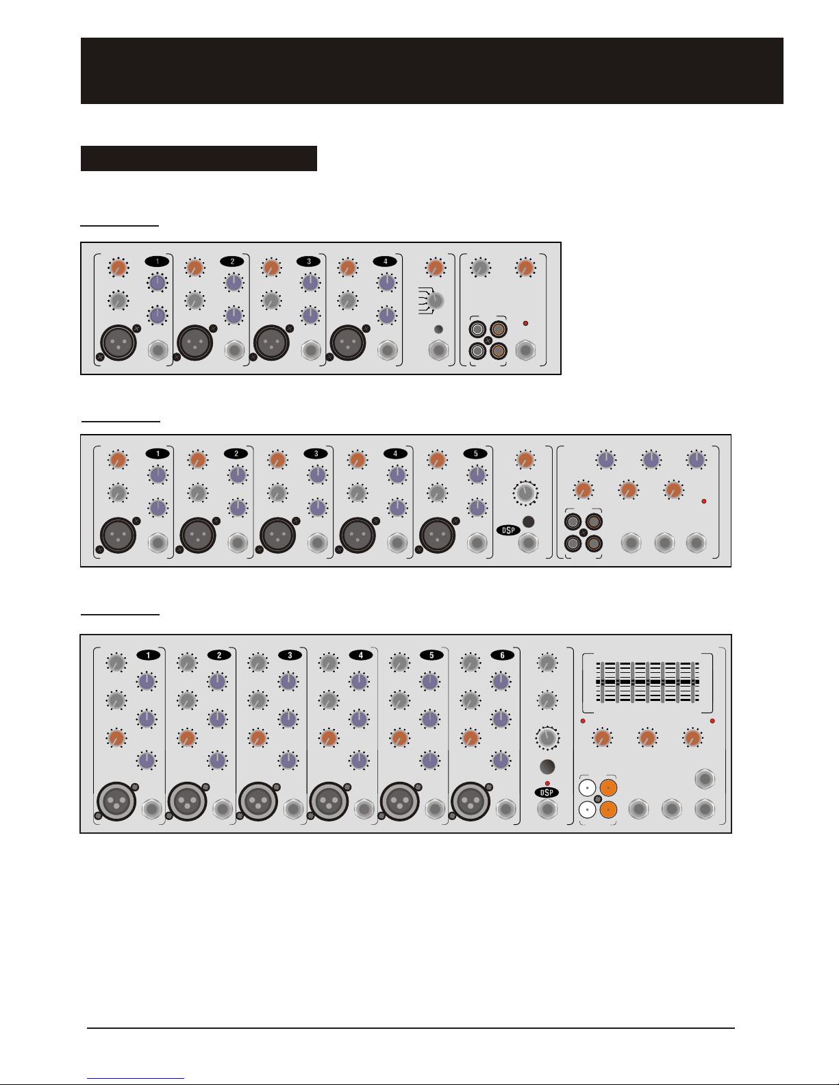
CD630M
FRONT PANEL FEATURES:
CD480M
77 77
11
99 99
33
1010 1010
44 4466 66
00 00
55 55
88 88
22
77 77
11
99 99
33
1010 1010
44 4466 66
00 00
55 55
88 88
22
77
11
99
33
1010
44 66
00
55
88
22
77
11
99
33
1010
44 66
00
55
88
22
FX FX FX
Gain Gain Gain
Line Line Line
Mic Mic Mic
Treb Treb Treb
Bass Bass Bass
22
44 44
22
11 11
55
33
33
5 5
-0+-0+
22
44 44
22
11 11
55
33
33
5 5
-0+-0+
22
44 44
22
11 11
55
33
33
5 5
-0+-0+
22
44 44
22
11 11
55
33
33
5 5
-0+-0+
22
44 44
22
11 11
55
33
33
5 5
-0+-0+
22
44 44
22
11 11
55
33
33
5 5
-0+-0+
77 77
1199 99
33
1010 1010
44 4466 66
00 00
55 55
88 88
22
77 77
1199 99
33
1010 1010
44 4466 66
00 00
55 55
88 88
22
77
11 99
33
1010
44 66
00
55
88
22
11 99
33
1010
44 66
00
55
88
22
CD516M
77
11 11
99
33 33
1010
44 66
00
55
88
22 22
77
11 11
99
33 33
1010
44 66
00
55
88
22 22
FXFX
GainGain
LineLine
MicMic
TrebTreb
BassBass
22
44 44
22
11 11
55
33
33
5 5
-0+-0+
22
44 44
22
11 11
55
33
33
5 5
-0+-0+
77
11 1199
33 33
1010
44 66
00
55
88
22 22
77
11 1199
33 33
1010
44 66
00
55
88
22 22
RemoteRemote
FX LevelFX Level
00
77
11 99
33
1010
44 66
00
55
88
22
REV1REV1
REV2REV2
REV3REV3
DLY1DLY1
DLY2DLY2
DLY3DLY3
FX OnFX On
LaneyLaney
00
77
11
99
33
1010
44 66
00
55
88
22
CD InCD In
CD InCD In
Main OutMain Out
VolumeVolume
CD480MCD480M
Rec OutRec Out
00
77
11
99
33
1010
44 66
00
55
88
22
PowerPower
CD Manual
LaneyLaney
77 77 77
11 11 1199 99 99
33 33 33
1010 1010 1010
44 44 4466 66 66
00 00 00
55 55 55
88 88 88
22 22 22
77 77 77
11 11 1199 99 99
33 33 33
1010 1010 1010
44 44 4466 66 66
00 00 00
55 55 55
88 88 88
22 22 22
77
11
99
33
1010
44 66
00
55
88
22
77
11
99
33
1010
44 66
00
55
88
22
77
11
99
33
1010
44 66
00
55
88
22
77
11
99
33
1010
44 66
00
55
88
22
FXFX FXFX FXFX FXFX FXFX
GainGain
GainGain GainGain GainGain GainGain
FX LevelFX Level
Main OutMain OutFX/Mon OutFX/Mon OutAux InAux InRemoteRemoteLineLine LineLine LineLine LineLine LineLine
MicMic MicMic MicMic MicMic MicMic
TrebTreb TrebTreb TrebTreb TrebTreb TrebTreb
BassBass BassBass BassBass BassBass BassBass
22
44
44
22
11 11
55
33
33
5 5
-0+-0+
22
44
44
22
11 11
55
33
33
5 5
-0+-0+
22
44
44
22
11 11
55
33
33
5 5
-0+-0+
22
44
44
22
11 11
55
33
33
5 5
-0+-0+
22
44
44
22
11 11
55
33
33
5 5
-0+-0+
22
44
44
22
11 11
55
33
33
5 5
-0+-0+
22
44
44
22
11 11
55
33
33
5 5
-0+-0+
22
44
44
22
11 11
55
33
33
5 5
-0+-0+
22
44
44
22
11 11
55
33
33
5 5
-0+-0+
22
44
44
22
11 11
55
33
33
5 5
-0+-0+
77 77 77
11 11 11
99
99 99
33 33 33
1010
1010 1010
44 44 4466 66 66
00 00 00
55
55 55
88 88 88
22
22 22
77 77 77
11 11 11
99
99 99
33 33 33
1010
1010 1010
44 44 4466 66 66
00 00 00
55
55 55
88 88 88
22
22 22
77
11
99
33
1010
44 66
00
55
88
22
11
99
33
1010
44 66
00
55
88
22
77
11
99
33
1010
44 66
00
55
88
22
11
99
33
1010
44 66
00
55
88
22
77 7777
11 1111 99 9999
33 3333
1010 10101010
44 4444 6666
00 0000
55 5555
88 8888
22 2222
77 7777
11 1111 99 9999
33 3333
1010 10101010
44 4444 66
66
66
00 0000
55 5555
88 8888
22 2222
CD InCD In
MiddleMiddleBassBass TrebleTreble
PowerPowerAux InAux In
22
44
44
22
11 11
55
33
33
5 5
-0+-0+
22
44
44
22
11 11
55
33
33
5 5
-0+-0+
22
44
44
22
11 11
55
33
33
5 5
-0+-0+
00
77
11 99
33
1010
44 66
00
55
88
22
CD516MCD516M
Rec OutRec Out
FX OnFX On
VolumeVolume
RotaryRotary
DelayDelay
ChorusChorus
OctaveOctave
Dly+ChDly+Ch
Rev+ChRev+Ch
FlangeFlange
33
44
11
22
11
22
RoomRoom
HallHall
11
22
11
22
MultitapMultitap
Laney
77 77 77 77 77 77
77 77 77 77 77 77
11 11 11 11 11 11
11 11 11 11 11 11
99 99 99 99 99 99
99 99 99 99 99 99
33 33 33 33 33 33
33 33 33 33 33 33
1010 1010 1010 1010 1010 1010
1010 1010 1010 1010 1010 1010
44 44 44 44 44 44
44 44 44 44 44 44
66 66 66 66 66 66
66 66 66 66 66 66
00 00 00 00 00 00
00 00 00 00 00 00
55 55 55 55 55 55
55 55 55 55 55 55
88 88 88 88 88 88
88 88 88 88 88 88
22 22 22 22 22 22
22 22 22 22 22 22
77 77 77 77 77 77
77 77 77 77 77 77
11 11 11 11 11 11
11 11 11 11 11 11
99 99 99 99 99 99
99 99 99 99 99 99
33 33 33 33 33 33
33 33 33 33 33 33
1010 1010 1010 1010 1010 1010
1010 1010 1010 1010 1010 1010
44 44 44 44 44 44
44 44 44 44 44 44
66 66 66 66 66 66
66 66 66 66 66 66
00 00 00 00 00 00
00 00 00 00 00 00
55 55 55 55 55 55
55 55 55 55 55 55
88 88 88 88 88 88
88 88 88 88 88 88
22 22 22 22 22 22
22 22 22 22 22 22
FX FX FX FX FX FX
Mon Mon Mon Mon Mon Mon
Gain Gain Gain Gain Gain Gain
Main Out
Mon Out
FX OutAux In
Line Line Line Line Line Line
Mic Mic Mic Mic Mic Mic
Treb Treb Treb Treb Treb Treb
22
44
44
22
11 11
55
33
33
5 5
-0+-0+
22
44
44
22
11 11
55
33
33
5 5
-0+-0+
22
44
44
22
11 11
55
33
33
5 5
-0+-0+
22
44
44
22
11 11
55
33
33
5 5
-0+-0+
22
44
44
22
11 11
55
33
33
5 5
-0+-0+
22
44
44
22
11 11
55
33
33
5 5
-0+-0+
22
44 44
22
11 11
55
33
33
5 5
-0+-0+
22
44 44
22
11 11
55
33
33
5 5
-0+-0+
22
44 44
22
11 11
55
33
33
5 5
-0+-0+
22
44 44
22
11 11
55
33
33
5 5
-0+-0+
22
44 44
22
11 11
55
33
33
5 5
-0+-0+
22
44 44
22
11 11
55
33
33
5 5
-0+-0+
22
44
44
22
11 11
55
33
33
5 5
-0+-0+
22
44
44
22
11 11
55
33
33
5 5
-0+-0+
22
44
44
22
11 11
55
33
33
5 5
-0+-0+
22
44
44
22
11 11
55
33
33
5 5
-0+-0+
22
44
44
22
11 11
55
33
33
5 5
-0+-0+
22
44
44
22
11 11
55
33
33
5 5
-0+-0+
77 77 77 77 77 77
11 11 11 11 11 1199 99 99 99 99 99
33 33 33 33 33 33
1010 1010 1010 1010 1010 1010
44 44 44 44 44 4466 66 66 66 66 66
00 00 00 00 00 00
55 55 55 55 55 55
88 88 88 88 88 88
22 22 22 22 22 22
77 77 77 77 77 77
11 11 11 11 11 1199 99 99 99 99 99
33 33 33 33 33 33
1010 1010 1010 1010 1010 1010
44 44 44 44 44 4466 66 66 66 66 66
00 00 00 00 00 00
55 55 55 55 55 55
88 88 88 88 88 88
22 22 22 22 22 22
777777
111111 999999
333333
101010101010
444444 666666
000000
555555
888888
222222
777777
111111 999999
333333
101010101010
444444 666666
000000
555555
888888
222222
CD/Aux In
VolumeMonitor Out
CD630M
Rec Out
CD In
80Hz 160Hz 400Hz 800Hz 2KHz 12KHz6KHz
0dB 0dB
-15 -15
+15 +15
Equalisation
Mid Mid Mid Mid Mid Mid
Bass Bass Bass Bass Bass Bass
PeakPower
RotaryRotary
ChorusChorus
OctaveOctave
FX Main
FX Mon
Remote
00
77
11 99
33
1010
44 66
00
55
88
22
00
77
11 99
33
1010
44 66
00
55
88
22
FX On
DelayDelay
Dly+ChDly+Ch
Rev+ChRev+Ch
FlangeFlange
33
44
11
22
11
22
RoomRoom
HallHall
11
22
11
22
MultitapMultitap
2Concept series

3
4
5
7
1 9
3
10
4 6
0
5
8
2
7
1 9
3
10
4 6
0
5
8
2
FX
Gain
Line
Mic
Treb
Bass
2
4
4
2
1 1
5
3
3
5
-0+
2
4 4
2
1 1
5
3
3
5
-0+
7
1
9
3
10
4 6
0
5
8
2
7
1
9
3
10
4 6
0
5
8
2
FEATURES CD480M
2
1
FX LEVEL: Sets the overall level of effects in the
master mix.
FX SELECT: Selects the onboard DSP program.
There are three reverbs and three delays to choose
from: -
REV 1 - SHORT REVERB
REV 2 - MEDIUM REVERB
REV 3 - LONG REVERB
DLY 1 - SHORT DELAY 110ms
DLY 2 - MEDIUM DELAY 150ms
DLY 3 - LONG DELAY 200ms
FX ON: Engages the onboard DSP effects.
REMOTE: Socket for connecting footswitch, which
allows the remote switching of the effects. Note for the footswitch to work correctly the effects need
to be enabled via the front panel first.
10
1
2
5
6
4
3
CD480M Features - Channels 1 - 4
CD480M Features - DSP
10
7
8
9
Remote
FX Level
0
7
1
9
3
10
4 6
0
5
8
2
REV1
REV2
REV3
DLY1
DLY2
DLY3
FX On
DSP
GAIN: Adjusts the channel level, enabling the user
to balance levels across channels.
FX: Controls the amount of signal sent by the
individual channel to the onboard effects section.
The overall level of effects is controlled via the FX
Level control.
MIC INPUT: XLR input for low impedance
microphone (200-600 Ohm).
LINE INPUT: Jack input socket, for all line level
signals (Keyboard, Signal Processor, Sampler,
Drum Machine, etc.).
BASS: Adjusts the low frequency response of the
individual channel.
TREBLE: Adjusts the mid & Hi range frequency
response of the individual channel.
6
7
8
9
CD Manual
3 Concept series

Laney
0
7
1 9
3
10
4 6
0
5
8
2
CD In
CD In
Main Out
Volume
CD480M
Rec Out
0
7
1 9
3
10
4 6
0
5
8
2
Power
13
14
17
FEATURES CD480M
12
11
13
CD480M Features - Rear Panel
CD IN VOLUME: Controls the overall listening level
if CD/MD/tape machine connected to the CD IN
sockets (12)
CD IN: PHONO sockets provided for connecting
external sound source such as CD/MD/Tape
machines.
REC OUT: PHONO sockets provided for
connecting external recording devices. Overall the
individual channel levels determine recording level.
MAIN OUT: Socket providing a line level signal for
connecting external power amplifiers should extra
sound reinforcement be required.
VOLUME: Sets the overall listening level of the
amplifier.
POWER: Main power switch
SPEAKER SOCKETS: Sockets for connecting
main front of house speakers. Minimum impedance
4 Ohms each side.
1111
15
12
LOUDSPEAKER OUTPUT
CLASS 2 WIRING MAY BE USED
CAUTION
REFER TO USERS MANUAL FOR
RECOMMENDED SPEAKER CONNECTIONS.
0
A TOTAL LOAD OF NO LESS THAN 4 OHMS
MAY BE CONNECTED AT ANY TIME.
Power
!!
CAUTIONCAUTION
RISK OF ELECTRIC SHOCK DO NOT OPENRISK OF ELECTRIC SHOCK DO NOT OPEN
Made in China Fabrique en Chine
Designed in the UK by BLT Industries LTD.
WARNING -TO REDUCE THE RISK OF FIRE OR ELECTRIC SHOCK
DO NOT EXPOSE THIS APPLIANCE TO RAIN OR MOISTURE.
CAUTION TO REDUCE THE RISK OF ELECTRIC SHOCK DO NOT
REMOVE COVERS. NO USER SERVICEABLE PARTS INSIDE.
REFER SERVICING TO QUALIFIED PERSONNEL ONLY.
CAUTION-FOR CONTINUED PROTECTION AGAINST RISK OF FIRE
REPLACE ONLY WITH SAME TYPE AND RATED
FUSE
WARNING-THIS EQUIPMENT MUST BE EARTHED.
ATTENTION - DEBRANCHER LE CORDON D’ALIMENTATION
AVANT TOUTE INTERVENTION.
AVIS - RISQUE DE CHOC ELECTRIQUE NE PAS OUVRIR.
ATTENTION - REMPLACER LE FUSIBLE SEULEMENT PAR
LE MEME TYPE ET LE MEME CALIBRE.
ATTENTION - SE REFERER AU MANUEL D’UTILISATION
POUR LA CONNECTION HAUT-PARLEURS.
Serial Number
N16 46N16 46N 1646N 1646
Power Consumption - 100 Watts ~50/60Hz
~100V AC 50/60Hz
CD480MModel
Power Source
Primary Fuse
~230V AC 50/60Hz
~120V AC 50/60Hz
~240V AC 50/60Hz
T2A L / 125V
T1A L / 250V
1
CD480M Features - Output section
14
17
16
15
16
CD Manual
4Concept series

FEATURES CD516M
3
4
5
7
1 9
3
10
4 6
0
5
8
2
7
1 9
3
10
4 6
0
5
8
2
FX
Gain
Line
Mic
Treb
Bass
2
4
4
2
1 1
5
3
3
5
-0+
2
4 4
2
1 1
5
3
3
5
-0+
7
1
9
3
10
4 6
0
5
8
2
7
1
9
3
10
4 6
0
5
8
2
2
1
FX LEVEL: Sets the overall level of effects in the master
mix.
FX SELECT: Selects the onboard DSP program. There
are 16 custom effects to choose from: -
250mS Single Shot
400mS Delay with Repeat
500mS Delay with Repeat
600mS Delay with Repeat
Flange
Flange + 400mS Delay (with Repeat)
Rotary Slow
Rotary Fast
Octave Down
Chorus Moderate
Chorus Deep
Hall Reverb
Room Reverb
Multitap Delay
400mS Delay (With Repeat) + Chorus
Deep
Chorus + Reverb
FX ON: Engages the onboard DSP effects.
REMOTE: Socket for connecting footswitch, which
allows the remote switching of the effects. Note - for the
footswitch to work correctly the effects need to be
enabled via the front panel first.
10
1
2
5
6
4
3
CD516M Features - DSP
10
7
8
9
GAIN: Adjusts the channel level, enabling the user
to balance levels across channels.
FX: Controls the amount of signal sent by the
individual channel to the onboard effects section.
The overall level of effects is controlled via the FX
Level control.
MIC INPUT: XLR input for low impedance
microphone (200-600 Ohm).
LINE INPUT: Jack input socket, for all line level
signals (Keyboard, Signal Processor, Sampler,
Drum Machine, etc.).
BASS: Adjusts the low frequency response of the
individual channel.
Treble: Adjusts the mid & Hi range frequency
response of the individual channel.
6
7
8
9
CD516M Features - Channels 1 - 5
FX LevelFX Level
RemoteRemote
00
77
11 99
33
1010
44 66
00
55
88
22
FX OnFX On
RotaryRotary
DelayDelay
ChorusChorus
OctaveOctave
Dly+ChDly+Ch
Rev+ChRev+Ch
FlangeFlange
33
44
11
22
11
22
RoomRoom
HallHall
11
22
11
22
MultitapMultitap
5 Concept series
CD Manual

27
18
19
24
24
CD IN VOLUME: Controls the overall listening level if CD/MD/tape machine connected to the CD IN
sockets (19)
CD IN: PHONO sockets provided for connecting external sound source such as CD/MD/Tape
machines.
REC OUT: PHONO sockets provided for connecting external recording devices. Overall the
individual channel levels determine recording level.
MAIN OUT: Socket providing a line level signal for connecting external power amplifiers should
extra sound reinforcement be required.
VOLUME: Sets the overall listening level of the amplifier.
AUX IN: Jack socket line in, designed to work in conjunction with the ‘Effect Out’ socket, as the
return of an effects loop. It can also be used as an additional input into the unit.
FX/MON OUT: Socket for providing external signal source for either using as a monitor send to a
powered monitor or as the send to an external effects processor. The return signal from the
processor should be connected to the AUX in socket (21). The level of each channel present at this
socket is determined by the individual gain controls of each channel.
Laney
Main OutFX/Mon OutAux In
77 7777
11 1111
99 9999
33 3333
1010 10101010
44 4444 6666
00 0000
55 5555
88 8888
22 2222
77 7777
11 1111
99 9999
33 3333
1010 10101010
44 4444 66
66
66
00 0000
55 5555
88 8888
22 2222
CD In
MiddleBass Treble
PowerAux In
22
44 44
22
11 11
55
33
33
5 5
-0+-0+
22
44 44
22
11 11
55
33
33
5 5
-0+-0+
22
44 44
22
11 11
55
33
33
5 5
-0+-0+
CD516M
Rec Out
Volume
FEATURES CD516M
CD516M Features - Output section
21 22 23
25
26
28
18
19
20
20
21
22
23
CD Manual
6 Concept series

POWER: Main power switch
SPEAKER SOCKETS: Sockets for connecting main front of house speakers. Minimimum
impedance 4 Ohms each side.
30
CD Manual
LOUDSPEAKER OUTPUT
CLASS 2 WIRING MAY BE USED
CAUTION
REFER TO USERS MANUAL FOR
RECOMMENDED SPEAKER CONNECTIONS.
A TOTAL LOAD OF NO LESS THAN 4 OHMS
MAY BE CONNECTED AT ANY TIME.
PowerPower
!!
CAUTION
RISK OF ELECTRIC SHOCK DO NOT OPEN
Made in China Fabrique en Chine
Designed in the UK by BLT Industries LTD.
WARNING -TO REDUCE THE RISK OF FIRE OR ELECTRIC SHOCK
DO NOT EXPOSE THIS APPLIANCE TO RAIN OR MOISTURE.
CAUTION TO REDUCE THE RISK OF ELECTRIC SHOCK DO NOT
REMOVE COVERS. NO USER SERVICEABLE PARTS INSIDE.
REFER SERVICING TO QUALIFIED PERSONNEL ONLY.
CAUTION-FOR CONTINUED PROTECTION AGAINST RISK OF FIRE
REPLACE ONLY WITH SAME TYPE AND RATED
FUSE
WARNING-THIS EQUIPMENT MUST BE EARTHED.
ATTENTION - DEBRANCHER LE CORDON D’ALIMENTATION
AVANT TOUTE INTERVENTION.
AVIS - RISQUE DE CHOC ELECTRIQUE NE PAS OUVRIR.
ATTENTION - REMPLACER LE FUSIBLE SEULEMENT PAR
LE MEME TYPE ET LE MEME CALIBRE.
ATTENTION - SE REFERER AU MANUEL D’UTILISATION
POUR LA CONNECTION HAUT-PARLEURS.
Serial Number
N16 46N16 46
Power Consumption - 300 Watts ~50/60Hz
~100V AC 50/60Hz
CD516MModel
Power Source
Primary Fuse
~230V AC 50/60Hz
~120V AC 50/60Hz
~240V AC 50/60Hz
T5A L / 125V
T2A L / 250V
FEATURES CD516M
CD516M Features - Output section
25
26
29
CD516M Features - Rear Panel
30
29
TREBLE: Adjusts the overall high frequency response of the amplifier.
MID: Adjusts the overall mid range frequency response of the amplifier.
AUX IN: Sets the overall level in the mix of any external devices connected to the AUX IN
socket.
BASS: Adjusts the overall low frequency response of the amplifier.
28
27
CD Manual
7
Concept series

FX: Controls the amount of signal sent by the
individual channel to the onboard effects section.
The overall level of effects is controlled via the FX
MAIN control.
TREBLE: Adjusts the high frequency response of
the individual channel.
MON: Controls the amount of signal sent from the
channel to the ‘Monitor’ output socket, giving the
user the versatility of a separate monitor mix.
MID: Adjusts the mid range frequency response of
the individual channel.
GAIN: Adjusts the channel level, enabling the user
to balance levels across channels.
BASS: Adjusts the low frequency response of the
individual channel.
MIC INPUT: XLR input for low impedance
microphone (200-600 Ohm).
LINE INPUT: Jack input socket, for all line level
signals (Keyboard, Signal Processor, Sampler,
Drum Machine, etc.).
FX MAIN: Sets the overall level of effects in the
master mix.
FX MON: Sets the overall level of effects in the
monitor mix.
PROGRAM: Selects the onboard DSP program.
See specification listed in the CD516M section
FX ON: Engages the onboard DSP effects. The
LED associated with the DSP shows when you have
selected the DSP section. (See note below)
REMOTE: Socket for connecting footswitch which
allows the remote switching of the effects. For the
footswitch to work correctly the effects need to be
enabled via the front panel first.
Note - With the footswitch connected please be
aware that when you switch the effects off with the
remote it does not effect the status of the LED - this
remains on even when the DSP is muted.
FEATURES CD630M
CD630M Features - Channels 1 - 6
77
77
11
11
99
99
33
33
1010
1010
444466
66
00
00
55
55
88
88
22
22
77
77
11
11
99
99
33
33
1010
10
444466
66
00
00
55
55
88
88
22
22
FX
Mon
Gain
Line
Mic
Treb
2
4
4
2
1 1
5
3
3
5
-0+
2
4 4
2
1 1
5
3
3
5
-0+
2
4 4
2
1 1
5
3
3
5
-0+
77
11
99
33
1010
44 66
00
55
88
22
7
11
99
3
1010
4 6
00
5
88
22
Mid
Bass
32
33
31
34
35
38
36
40
37
41
43
39
32
43
31
33
34
35
36
37
38
39
40
41
CD Manual
FX Main
FX Mon
Remote
00
77
11
99
33
1010
44 66
00
55
88
22
00
77
11 99
33
1010
44 66
00
55
88
22
FX On
DelayDelay
Dly+ChDly+Ch
Rev+ChRev+Ch
FlangeFlange
33
44
11
22
11
22
RoomRoom
HallHall
11
22
11
22
MultitapMultitap
42
42
8 Concept series

Laney
Main Out
Mon Out
FX OutAux In
777777
111111 999999
333333
101010101010
444444 666666
000000
555555
888888
222222
777777
111111 999999
333333
101010101010
444444 666666
000000
555555
888888
222222
CD/Aux In
VolumeMonitor Out
CD630M
Rec Out
CD In
80Hz 160Hz 400Hz 800Hz 2KHz 12KHz6KHz
0dB 0dB
-15 -15
+15 +15
Equalisation
PeakPower
45
5
54
GRAPHIC EQ: 7 band graphic
equalizer.
CD/AUX IN: Sets the overall level
in the mix of any external devices
connected to the CD IN and AUX
IN sockets.
CD IN: Dual phono, line level
input sockets, ideal for connecting
an external tape machine, CD
player, etc. to the amplifier.
REC OUT: Dual phono, line level
output sockets, ideal for
connecting an external recording
device.
AUX IN: Jack socket line in,
designed to work in conjunction
with the ‘Effect Out’ socket, as the
return of an effects loop.
FX/MON OUT: Socket for
providing external signal source
for either using as a monitor send
to a powered monitor or as the
send to an external effects
processor. The return signal from
the processor should be
connected to the AUX in socket
(21). The level of each channel
present at this socket is
determined by the individual gain
controls of each channel.
FEATURES CD630M
CD630M Features - Output section
45
46
47
48
49
50
51
52
53
44
54
44
46
47
48
MAIN OUT: Socket providing a line level signal for connecting external power amplifiers
should extra sound reinforcement be required.
VOLUME: Sets the overall listening level of the amplifier.
MON OUT: Line level signal provided for connecting to an external powered monitor or
connecting to an external power amplifier supplying un-powered monitors. The Level of
signal present at this socket is determined by the individual MONITOR level of each channel.
MONITOR OUT: Determines the overall level of signal sent to an external monitoring power
source.
PEAK LED: Indicates that the output section is overloading and unwanted distortion may
result. Reduce the output level until the LED remains off.
49
50
51
52
53
CD Manual
9 Concept series

Laney
BLT Industries Ltd.,
Newlyn Road,
Cradley Heath,
West Midlands.
B64 6BE.
United Kingdom
In the interest of continued product development BLT Industries Ltd. reserves the right to amend product
specification without prior notification.
e
o
Te
c
hn
i
ca
l
S
p
cif
i
ca
t
i
ns
C
D
0 D5
6
C
3 M
4
8
M C 1
M
D
6
0
e t i
:
Ch n
lsS
ns
i iv ty
a n
e
:
Ch
-
5 I
3 V (
2
d
) mp
d
c 0 0
2 B
)
Im
p a c
0
5 mV (
d
u) d
n
e 1
1
C
h
Line n
5m -
7
B
u I e
a
n
e 1 K 5
m
V (- 3d u
ed n e
1
K
0 -2
3
B
Impe
a
c
0K
C
h
-
5 c
n
t 2 5
-5
B B n
d .5
- 7
B
u
Ba c
d
1
3
4
d ) l
n
e K
1
C
h Mi I
p
u
. mV (
0
d
u) ala
c
e
1K 3
m
V ( 4 d
)
lan e
K
.5mV
(-
7
Bu Ba
a
c
d 1
A
u
N/A
2 mV
(
1
d u e
n e 1 2
0
- B
I
p a c
Kx
In: 2 0
-1
B ) Imp
d
a
c 0K
2
m
V
( 1
1d u
)
m
ed n e
1
0
CD I :
2
m - d
)
mp d c
0 0
m
V
( B ) Im
p
a c 0
3
0
- d
u
d n
e
1
n 0
0
V ( 8 B
u
I
e an
e
1
K 3 0
-8d u e
d
n e 1 K
0
m
V ( 8 B
)
Im
pe a c
0
K
Re
t:
3
m -
d
) 0
m
V ( B
)
3 0 -
d
u
c O
u
0
0 V ( 8
B
u
3
0
-8d u
0 mV (
8
B
)
Ma
n
1 3 4
B
)
.3
4 u
1
B
i
O
u
t: . V ( d
1
V
( dB )
.3V (4
d
u
)
M
o
t N/A 2 mV (
B
4 0
- d )
n
O
u : 4
0 -5
d
)
2 m
V
(
5 B
p
C
n e
Q
:
C
h
n l a
C
o t o ± d
t H
h
i g 2 d 4
Hz e v
g
± 0
t 0
h
l
in
In u
t
h
a n l E
a
ne B s
s
n r l 20
B
a
40 z S
e
lv
n ± 0 B a
t
0
Sh l in
2 d
B
a
4 Hz S
e
v
g
C
h n l
d
le C t
l
N
/A
/ ±
2
t 0 z
S
lv na ne M
id
on ro
N A 1
d
B
a 1 KH
h
e i g
Ch n l
r
b
e n r
l
±
d
t K
S
h l in 1 d
1 K
h
i g ±
2
t 0
z
S lv n
a ne T
e
l
Co t o
1
2
B
a 10 H
z
e v g
± 2 B
a
t
0 Hz S
e
lv
n 1
d
B a 1 K
H
he i g
a r E
Ma t
r
s n
o
±
d t
H
h i
g
2
d
4 H
z
e v g 7 n h
M
ste Q
:
s e
B
a
s Co tr
l
2
0 B a 4
0
z
S elv n
±
0
B
at 0 S
h
l in Ba d G
ra
p
ic EQ
Ma
t
r
d l
o
t
o ± d
t
0 S l
n
1
d 5
0
h l in ± 2 B
a
h
B ds
e
M
i d e C
n
r
l 12 B a
5
0
Hz
he
v
i
g
±
2
B at 0
H
z
S e v g 1 d E
c
an
M
a
t
r le
C
o
t ± d
t
K Sh
l
in
1
d 1
K
h i
g
"8 1
0
4
,8 ,
K
6
2
s
e
Treb
n
rol 12 B
a
1
0 Hz e
v
g ±
2
B at 0
H
z
S elv n
0, 6
,
0
0
00 2
,
K
,1 K"
r
q
e
y s
o
e 2 z
2
KH 3
0 z 2
H
d 2
H
K
3
BF
e
u
n
c Re p
n
s
: 0H
-
0
z ± d
B
2 H - 0
K
z
±3 B 0
z
-2
0 Hz ±
d
i
it l e
t
6
P
o r ms
6
r ms 1
r g a
D
g
a Eff c
:
r
g a 1 P
ro
g
a 6
P
o r ms
u p t
e : N
A Y
e
,
t a Y s Op
ic
w th S a
u
E
O t u L
im
it
r /
s
O
p ic l e , t
a
l
i t t
s
L
D
o t
w
t
h N A D
i it l f
t
t o D g
a
e
f c Mu
e
/ ff
F o s
i
c
: /
g a e fe
c
M
u e
n/o
ff
i it
l
f
e t t
o
n
o
u
p
t we
:
P
o r t
u
i to 4 o
m
s
6
16 W 0O
t
u
Po r
we Ou
p
t
n
h
5
W
5 30
W
Po r
t
u i to 8 o
m
s
4
W
1 W
0we O
u
p
t n
h
5
10 2
0
W
H N
T
p c l
0
0
% T
ic
.0
p ll
0
%
T
D%+ y
i a ly <
.
3
y
p
a
lly <0
3
%
T
y ica y
<
.0
3
N M
a
t
r - 0 B
-
2
9 BS R:
s
e
0 9 d 9
d
B - 0d
M
a
t r - 9 B
-
4 7 B
s
e 10 6 d 8
dB - 6d
C
h
n lX 1
- 6
B
- 5 6
B
a
ne 0
6 d
7 dB - 3
d
C
h n ls
1
-
0
B
- 8 5
Ba ne
0
6
d
6 dB
-
5
d
o r n
u
:
T
p
c l 3
W 7 5
P
we Co
s
m
ption (
y
i
a ) 0
0W
1
0
W
i e
io
: W* (
3 0 6
*
5
4
* 6 * 0
8 2
4
8
D m n
s
n
s ( D*H
)
m
m) 6 *
2 4
1
0
7
0
2 4 15
26 * 6
*1
0
ig
7 9 Kg KWe
h
t:
Kg
12 g
 Loading...