

Page 1

Laney
Page 2
Laney
11
INTRODUCTION
Congratulations on your decision to purchase a Laney amplifier.
Laney products are designed with ease of operation as a primary objective, however to ensure you derive the best from your new
amplifier, it is important you take time to read this user manual and to familiarise yourself with the control functions and facilities
available
BEFORE
SWITCHING ON
After unpacking your amplifier check that it is factory fitted with a three pin 'grounded' (or earthed) plug. Before plugging into the
power supply ensure you are connecting to a grounded earth outlet.
If you should wish to change the factory fitted plug yourself, ensure that the wiring convention applicable to the country where the
amplifier is to be used is strictly conformed to. As an example in the United Kingdom the cable colour code for connections are as
follows.
EARTH OR GROUND - GREEN/YELLOW
NEUTRAL - BLUE
LIVE - BROWN
This manual has been written for easy access of information. The front and rear panels of each unit are graphically illustrated, with
each control and feature numbered. For a description of the function of each control feature, simply check the number with the
explanations adjacent to each panel.
Your Laney valve amplifier has undergone a thorough two stage, pre-delivery inspection, involving actual play testing, as well as
valve burn in. Valves are the most important component in your Laney valve amp. However they are also the most fragile
component. The glass envelope and valve filaments can easily be damaged in transit without any apparent signs of damage to the
box, amp or valves. Valve damage is however quite simple to diagnose and even more simple to remedy. These procedures are
explained later in this manual..
When you first receive your Laney valve amp, follow these simple procedures:
(I) Ensure that the amplifier is set at the correct voltage for the country it is to be used in.
(ii) Ensure that the speaker is connected to the appropriate socket.
(iii) Connect your instrument with a high quality shielded instrument cable. Use of cheap cables will compromise the sound of
your instrument and your amplifier.
If there is a problem with your Laney valve amplifier
DON'T
DO
PHONE YOUR DEALER!
Care of your Laney amplifier will prolong it's life.....and yours!. If you follow these guidelines your equipment will give you
years of playing pleasure
Page 3
Laney
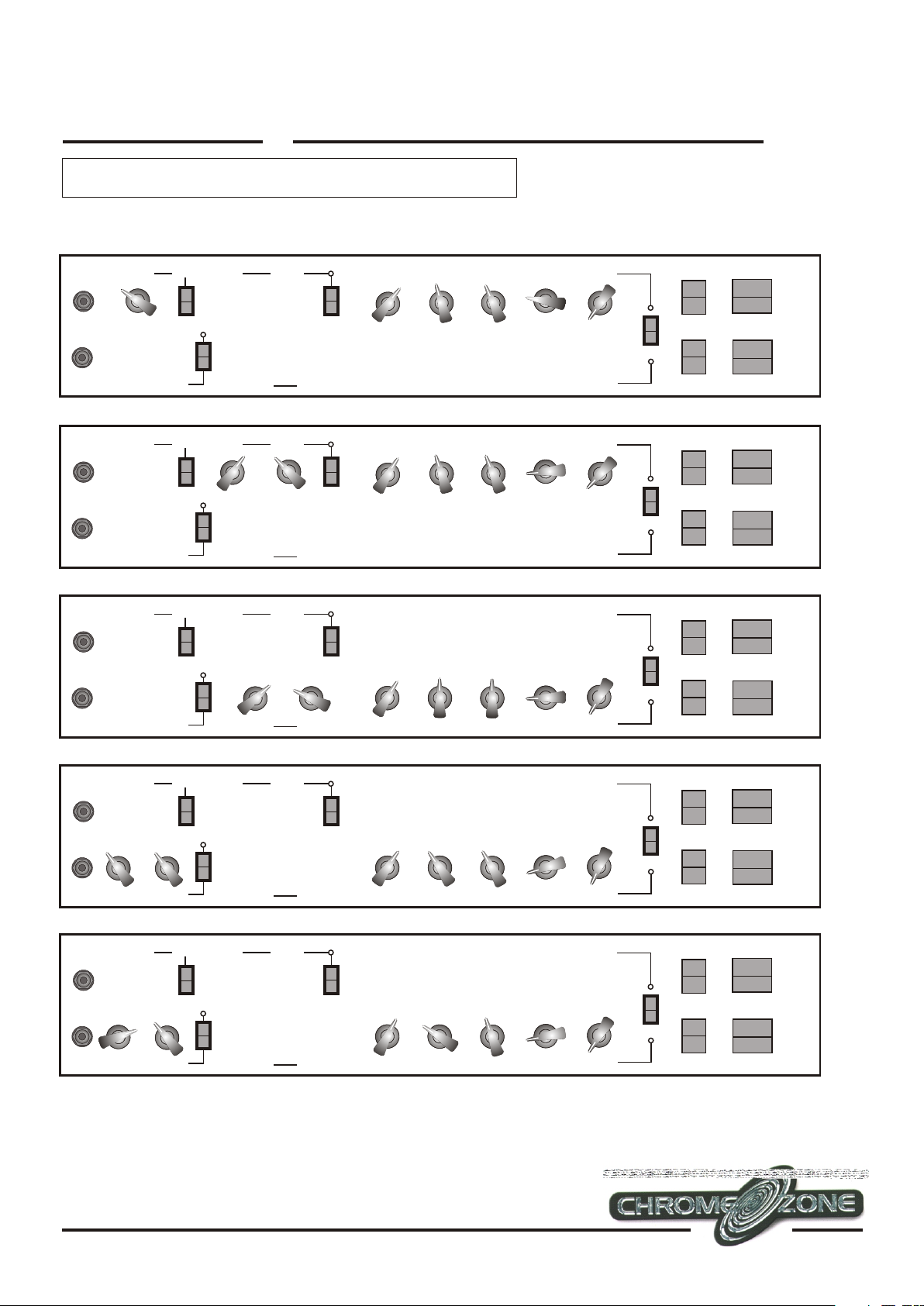
Suggested settings
N.B
Both the HI and the LO inputs should be experimented with to obtain the type of sound you are looking for. Reverb and Effects
Clean
VOLUME
4
3
2
LO
1
INPUT
0
5
6
4
3
2
HI
1
0
10
DRIVE
Clean Crunch
VOLUME
4
3
2
LO
1
INPUT
0
5
6
4
3
2
HI
1
0
10
DRIVE
BRIGHT
5
6
7
8
9
10
5
4
7
3
8
2
9
1
0
VOLUME
BRIGHT
5
6
7
8
9
10
5
4
7
3
8
2
9
1
0
VOLUME
DRIVE
4
3
2
1
0
6
7
8
9
10
DRIVE
4
3
2
1
0
6
7
8
9
10
VOLUME
5
3
2
1
5
3
2
1
5
6
7
8
9
10
4
0
GAIN
6
7
8
9
10
4
0
GAIN
6
4
3
7
8
2
9
1
0
10
5
5
6
7
9
10
VOLUME
3
2
1
6
7
9
10
5
6
4
3
8
4
0
8
7
8
2
9
1
0
10
VOLUME
5
6
7
8
9
10
5
6
4
3
7
8
2
9
1
0
10
VOLUME
BASS
4
3
2
1
0
4
3
2
1
0
BASS
BASS
4
3
2
1
0
4
3
2
1
0
BASS
MIDDLE
5
6
4
3
7
8
2
9
1
0
10
5
6
4
3
7
8
2
9
1
0
10
MIDDLE
MIDDLE
5
6
4
3
7
8
2
9
1
0
10
5
6
4
3
7
8
2
9
1
0
10
MIDDLE
TREBLE
5
6
4
7
3
8
2
9
1
10
0
5
6
4
7
3
8
2
9
1
10
0
TREBLE
TREBLE
5
6
4
7
3
8
2
9
1
10
0
5
6
4
7
3
8
2
9
1
10
0
TREBLE
5
6
7
8
9
10
5
6
7
8
9
10
5
6
7
8
9
10
5
6
7
8
9
10
REVERB EFFECTS
5
6
4
3
2
1
0
4
3
2
1
0
REVERB EFFECTS
REVERB EFFECTS
4
3
2
1
0
4
3
2
1
0
REVERB EFFECTS
3
7
2
8
1
9
10
5
6
3
7
2
8
1
9
10
5
6
3
7
2
8
1
9
10
5
6
3
7
2
8
1
9
10
5
6
4
7
8
9
0
10
5
6
4
7
8
9
0
10
5
6
4
7
8
9
0
10
5
6
4
7
8
9
0
10
TRIODE
PENTODEPENTODE
CHANNEL
DAMPING
TRIODE
PENTODEPENTODE
CHANNEL
DAMPING
22
RUNRUN
STANDBY
1
0
POWER
RUNRUN
STANDBY
1
0
POWER
Rock Rhythm
VOLUME
4
3
2
LO
1
INPUT
0
5
6
4
3
2
HI
1
0
10
DRIVE
Blues Lead
VOLUME
4
3
2
LO
1
INPUT
0
5
6
4
3
2
HI
1
0
10
DRIVE
Rock Lead
VOLUME
4
3
2
LO
1
INPUT
0
5
6
4
3
2
HI
1
0
10
DRIVE
BRIGHT
5
6
7
8
9
10
5
4
7
3
8
2
9
1
0
VOLUME
BRIGHT
5
6
7
8
9
10
5
4
7
3
8
2
9
1
0
VOLUME
BRIGHT
5
6
7
8
9
10
5
4
7
3
8
2
9
1
0
VOLUME
DRIVE
4
3
2
1
0
6
7
8
9
10
DRIVE
4
3
2
1
0
6
7
8
9
10
DRIVE
4
3
2
1
0
6
7
8
9
10
VOLUME
5
3
2
1
5
3
2
1
5
3
2
1
5
6
7
8
9
10
4
0
GAIN
6
7
8
9
10
4
0
GAIN
6
7
8
9
10
4
0
GAIN
6
4
3
7
8
2
9
1
0
10
5
5
5
6
7
9
10
VOLUME
3
2
1
6
7
9
10
VOLUME
3
2
1
6
7
9
10
5
6
4
3
8
4
0
8
4
0
8
7
8
2
9
1
0
10
VOLUME
5
6
7
8
9
10
5
6
4
3
7
8
2
9
1
0
10
VOLUME
5
6
7
8
9
10
5
6
4
3
7
8
2
9
1
0
10
VOLUME
BASS
4
3
2
1
0
4
3
2
1
0
BASS
BASS
4
3
2
1
0
4
3
2
1
0
BASS
BASS
4
3
2
1
0
4
3
2
1
0
BASS
MIDDLE
5
6
4
3
7
8
2
9
1
0
10
5
6
4
3
7
8
2
9
1
0
10
MIDDLE
MIDDLE
5
6
4
3
7
8
2
9
1
0
10
5
6
4
3
7
8
2
9
1
0
10
MIDDLE
MIDDLE
5
6
4
3
7
8
2
9
1
0
10
5
6
4
3
7
8
2
9
1
0
10
MIDDLE
TREBLE
5
6
4
7
3
8
2
9
1
10
0
5
6
4
7
3
8
2
9
1
10
0
TREBLE
TREBLE
5
6
4
7
3
8
2
9
1
10
0
5
6
4
7
3
8
2
9
1
10
0
TREBLE
TREBLE
5
6
4
7
3
8
2
9
1
10
0
5
6
4
7
3
8
2
9
1
10
0
TREBLE
5
6
7
8
9
10
5
6
7
8
9
10
5
6
7
8
9
10
5
6
7
8
9
10
5
6
7
8
9
10
5
6
7
8
9
10
REVERB EFFECTS
5
6
4
3
2
1
0
4
3
2
1
0
REVERB EFFECTS
REVERB EFFECTS
4
3
2
1
0
4
3
2
1
0
REVERB EFFECTS
REVERB EFFECTS
4
3
2
1
0
4
3
2
1
0
REVERB EFFECTS
3
7
2
8
1
9
10
5
6
3
7
2
8
1
9
10
5
6
3
7
2
8
1
9
10
5
6
3
7
2
8
1
9
10
5
6
3
7
2
8
1
9
10
5
6
3
7
2
8
1
9
10
5
6
4
7
8
9
0
10
5
6
4
7
8
9
0
10
5
6
4
7
8
9
0
10
5
6
4
7
8
9
0
10
5
6
4
7
8
9
0
10
5
6
4
7
8
9
0
10
TRIODE
PENTODEPENTODE
CHANNEL
DAMPING
TRIODE
PENTODEPENTODE
CHANNEL
DAMPING
TRIODE
PENTODEPENTODE
CHANNEL
DAMPING
RUNRUN
STANDBY
1
0
POWER
RUNRUN
STANDBY
1
0
POWER
RUNRUN
STANDBY
1
0
POWER
The above setting are examples only. Many variations of these settings can be achieved using a combination of Pentode/Triode and
Damping settings. Please experiment as much as possible when searching for your ideal tone.
Page 4

Laney
Model ChromeOzone
33
1a
INPUT
1b
2
VOLUME
4
3
2
LO
1
0
5
6
4
3
2
HI
1
0
10
DRIVE
19
3
BRIGHT
5
6
7
8
9
10
5
6
4
7
3
8
2
9
1
0
10
VOLUME
4
DRIVE
5
4
3
2
1
0
7
8
9
3
2
1
5
VOLUME
5
6
4
7
3
8
2
9
1
10
0
5
6
4
7
3
8
2
9
GAIN
1
10
0
18
Explanation of terms
1a
2
3
4
5
6
7
8
9
LO INPUT: This input is attenuated down approximately 6dB from the high input. It is useful in obtaining output
that is 'tight' not 'mushy' from high-gain humbucker-type pickups.
VOLUME: Adjusts the overall volume of the clean channel.
BRIGHT SWITCH: Adds brightness and sparkle to the upper frequencies of the clean and clean-drive-channel.
DRIVE: This pot controls the amount of valve-drive applied to the circuit.
VOLUME: Sets the overall volume-level of the clean-channel-drive-sound.
DRIVE SWITCH: Engages the clean-channel-drive-sound (also footswitchable).
BASS: Controls the low-frequency-EQ in the pre-amplifier.
MIDDLE: Controls the mid-frequency-EQ in the pre-amplifier.
TREBLE: Controls the high-frequency-EQ in the pre-amplifier.
REVERB: Controls the level of reverb assigned to each channel.
6
7
8
9
10
4
0
VOLUME
6
5
6
7
8
9
10
7
BASS
5
4
3
2
1
0
5
4
3
2
1
0
BASS
8
MIDDLE
5
6
4
3
7
8
2
9
1
0
10
5
6
4
3
7
8
2
9
1
0
10
MIDDLE
9
TREBLE
6
4
7
3
8
2
9
1
10
0
6
4
7
3
8
2
9
1
10
0
TREBLE
5
6
7
8
9
10
5
6
7
8
9
10
10
REVERB EFFECTS
5
4
3
2
1
0
5
4
3
2
1
0
REVERB EFFECTS
11
6
4
3
7
2
8
1
9
0
10
6
4
3
7
2
8
1
9
0
10
12
13
5
6
7
8
9
10
5
6
7
8
9
10
TRIODE
PENTODEPENTODE
CHANNEL
DAMPING
14
RUNRUN
STANDBY
1
0
POWER
151617
11
10
11
12
13
EFFECTS: Controls the signal-level upon its return from an external processor and blends it to the desired level
with the main signal.
CHANNEL SWITCH: This switches between channel A and channel B. The current channel is indicated via an
illuminated indicator. The upper channel produces the clean-tone and mild-overdrive that is reminiscent of a sixties
American valve-combo. The lower channel produces the more substantial overdrive and distortion that is often
associated with British valve-stacks.
TRIODE/PENTODE SWITCH: The Triode/Pentode switch allows the output of the power-amp section to be
switched between approximately 30 watts and 12watts. The reduction in output is achieved by switching the
power-amp valves from Pentode operation to Triode operation. Valves operating in Triode-mode are much less
efficient than valves operating in Pentode-mode, resulting in a volume reduction of around a third. There is also a
corresponding reduction in the level of gain between the two modes of operation. Additionally, when the amplifier
is operating in Triode mode the valves distort more softly producing a warmer distorted-tone.
Page 5

Laney
Model ChromeOzone
44
1a
INPUT
1b 151617
2
VOLUME
4
3
2
LO
1
0
5
6
4
3
2
HI
1
0
10
DRIVE
191b 151617
191b 151617
19
3
BRIGHT
5
6
7
8
9
10
5
6
4
7
3
8
2
9
1
0
10
VOLUME
18
18
18
4
DRIVE
5
4
3
2
1
0
7
8
9
3
2
1
5
VOLUME
5
6
4
7
3
8
2
9
1
10
0
5
6
4
7
3
8
2
9
GAIN
1
10
0
Explanation of terms
14
15
STANDBY SWITCH: This switch should be used in conjunction with the power-switch when both switching- on and
switching-off the amplifier. Before the amplifier is turned on, make sure the STANDBY switch is in the STANDBY
position. Throw the power switch, wait for 30 seconds, and then switch the STANDBY switch to RUN; the amplifier is
now fully functional. When powering-down the amplifier, the STANDBY switch should be switched from RUN to
STANDBY before the power-switch is switched off. The STANDBY switch can also be used mid-performance when a
silent guitar-change is required.
DAMPING: The damping control allows three levels of damping to be applied to the output-section of the
ChromeOzone. With the rocker-switch set centrally, a low-level of damping is applied to the output-section; if set to
position I a medium level of damping-effect is applied; correspondingly, switching to position II incurs a high level of
damping-effect. As a general rule, the higher the level of damping applied to the power-amp section, the tighter the
sound appears. When comparing an amplifier run with a low-level of damping with an amplifier run with a high-level
of damping, one will notice the following differences. The amplifier running with a low-level of damping will have an
increased bottom-end combined with an extended high-frequency response. Conversely, an amplifier running with a
high-level of damping will sound punchier, have a tighter low-end response and a reduced high-frequency brightness.
6
7
8
9
10
4
0
VOLUME
6
5
6
7
8
9
10
7
BASS
5
4
3
2
1
0
5
4
3
2
1
0
BASS
8
MIDDLE
5
6
4
3
7
8
2
9
1
0
10
5
6
4
3
7
8
2
9
1
0
10
MIDDLE
9
TREBLE
6
4
7
3
8
2
9
1
10
0
6
4
7
3
8
2
9
1
10
0
TREBLE
5
6
7
8
9
10
5
6
7
8
9
10
10
REVERB EFFECTS
5
4
3
2
1
0
5
4
3
2
1
0
REVERB EFFECTS
11
6
4
3
7
2
8
1
9
0
10
6
4
3
7
2
8
1
9
0
10
12
13
5
6
7
8
9
10
5
6
7
8
9
10
TRIODE
PENTODEPENTODE
CHANNEL
DAMPING
14
RUNRUN
STANDBY
1
0
POWER
VOLUME: Controls the volume of channel B.
16
17
GAIN: Controls the level of gain in channel B.
VOLUME: Controls the overall volume level of the switchable DRIVE feature (19). This volume control is
independent of volume controls (16), (2) and (5).
18
DRIVE: Controls the level of drive when the footswitchable-drive is activated.
19
LO INPUT: Should be used for guitars which feature passive and/or single-coil pickups. In comparison to the HI input
socket, the LO input is attenuated down -6dB. When connecting your guitar it is best to try each of the input sockets in
1b
order to acquire the sound that suits you best.
Explanation of terms
8 OHM
EXTENSION
CABINET
23
4 OHM
24
20
21
HT FUSE
22
INTERNAL
CABINET
25
LINE
OUT
IN
POWER
PRE
AMP AMP
26
27 28
FOOTSWITCH
INSERT
RETURN
LEVEL
INSERT
RETURN SEND
SIDE
CHAIN
29 30 31
BYPASS
32
EFFECTS LOOP
SEND RETURN
OVERDRIVE CHANNEL B
33
RETURN
34
EFFECTS LOOP
A+B
SEND
RETURN
CLEAN CHANNEL A
36
35 37
Page 6

Laney
POWER SOCKET: For connecting amplifier to mains power-supply.
20
POWER FUSE: This fuse protects the AC power of the overall amplifier. Use ONLY the correct size and rating of
21
fuse as specified on the panel. If a fuse blows or fails and a replacement of the same size and rating is installed and this
in turn blows, the amplifier has suffered an internal malfunction. At this point immediate service from a qualified
technician is required; DO NOT TRY USING A FUSE OF HIGHER RATING.
HT FUSE: This fuse protects the DC power within the amplifier. Use only the correct size and rating fuse as specified
22
on the panel. If a fuse blows or fails and a replacement of the same size and rating is installed and it in turn blows, the
amplifier has suffered a malfunction, at this point check the output valves and replace faulty one if required. Should
the valves not be the problem, the amplifier should be checked out by a qualified technician; DO NOT TRY USING A
FUSE OF GREATER VALUE. Using fuses that are too large in current rating may cause serious irreparable damage
to the amplifier. Fuses are designed-in to PROTECT, DO NOT take chances.
EXTENSION SPEAKER SOCKET: This is the socket to which you should connect an 8 Ohm extension cabinet.
23
When an extension cabinet is connected, the resultant impedance will be 4 Ohms and the speaker impedance-switch
should be set to 4 Ohms. Mismatched impedance will reduce the amplifiers performance and in some cases may cause
damage to your amplifier.
IMPEDANCE SELECTOR SWITCH: This switches the internal impedance setting of the amplifier. When using
24
with the 'on board' speaker set to 8 ohms. When an 8 ohm extension cabinet is also connected, set to 4 ohms.
INTERNAL SPEAKER SOCKET: 1/4" output-jack factory-connected to the 'on-board' speaker. With no
extension cabinet connected, ensure the impedance-selector-switch (24) is set to 8 ohms.
25
POWER AMP/LINE IN: This socket is provided to allow a signal to be fed directly to the power-amplifier from
either an effects-unit or another pre-amplifier. Connection at this point disconnects the internal pre-amplifier:
26
nominal level 0dBu.
55
POWER AMP/LINEOUT: This socket provides an output from the pre-amplifier, post effects-loop and may be used
to drive other power-amplifiers, effects-units or mixing-desks: nominal level 0dBu.
27
FOOTSWITCH SOCKET: This is a 5-pin 180 DIN socket for connection of the dedicated footswitch (FS4) as
supplied with the amplifier. The FS4 is a four-way-switch that facilitates remote-operation of both channels and
reverb.
28
RETURN LEVEL: This control adjusts the signal-level returning from an external effects-unit and allows the
correct mix to be achieved. Regardless of whether an effects-unit is connected, the return-level can be used to provide
additional pre-amplifier gain for both channels. This is a useful feature when, for example, you might want total
29
valve-saturation but a low output-level. This is performed by switching the INSERT MODE SWITCH (31) to
INSERT. This allows you to increase the pre-amplifier's volume and gain controls and control the output-level via the
RETURN-LEVEL rotary control. This process can also be applied in reverse; that is, increasing the power-amplifier
gain via the RETURN-LEVEL and controlling the output-level with the controls on the front-panel; turning the
RETURN-LEVEL fully-clockwise facilitates a gain increase of approximately 3dB. It is important to realise that the
RETURN-LEVEL and the volume and gain controls on the front-panel operate in tandem, offering a wide spectrum
of tonal response.
RETURN SOCKET:This is provided to receive the output of an external effects-unit being driven from the send
socket (32).
30
EFFECTS MODE SWITCH: For normal amplifier operation without effects this should be set to the BYPASS
position. When the whole of the amplifier signal is required to be directed to an external effect, such as a Graphic-EQ,
the switch should be set to INSERT mode. The SIDE CHAIN mode allows the connection of effects-units such as
31
delays, flangers, etc., where a direct signal-path is maintained to avoid the normal loss of dynamics through effectsprocessors. When using this mode any effects-unit should, if possible, be set to 'EFFECT ONLY' mode.
EFFECTS SEND SOCKET: This provides an output from the pre-amplifier to drive effects-units in conjunction
with (30) & (31). Nominal level 0dBu.
EFFECTS LOOP SEND (OVERDRIVE CHANNEL): This socket provides an output from the pre-amplifier for
32
sending to an external effects-processor. Processors fitted here operate in a 'side chain' mode and should be set for
effect only operation if possible; nominal level 0dBu.
33
Page 7

Laney
66
34
EFFECTS LOOP RETURN (OVERDRIVE CHANNEL): This socket is provided to accept the output of an
external effects-processor being driven from (33). The return-level mix is controlled via the front panel effects
level control.
35
EFFECTS LOOP RETURN A+B: This socket is provided for use when a single effects unit is to be used, on both
channels, at different mix levels, via the front panel effect level controls. In this set-up the effects-units may be
driven from either channel-send sockets.
36
EFFECTS LOOP RETURN (CLEAN CHANNEL): This socket is provided to accept the output of an external
effects-processor being drive from (37). The return-level mix is controlled via the front panel effects control.
EFFECTS LOOP SEND (CLEAN CHANNEL): This socket provides an output from the pre-amplifier for
37
sending to an external FX processor. Processors connected here operate in the 'side chain' mode so should be set for
effect only operation if possible. Nominal level 0dBu.
Ancillary Connection Examples
EXTENSION
CABINET
4 OHM
power amplifier
HT FUSE
LaneyLaney
8 OHM
INTERNAL
CABINET
Slave
In via power
amp socket
LINE
IN
POWER
AMP AMP
OUT
PRE
Nominal Level 0dBu
6L6
5881
FOOTSWITCH
EL34
BIAS
RETURN
LEVEL
RETURN SEND
EG. Multi-FX unit
in 'side chain' mode
INSERT
INSERT
SIDE
CHAIN
FX.C
BYPASS
EFFECTS LOOP
SEND RETURN
OVERDRIVE CHANNEL B
FX.A
EG. Slap back delay
RETURN
EFFECTS LOOP
A+B
SEND
RETURN
CLEAN CHANNEL A
FX.B
EG. Chorus
or Graphic EQ in insert mode
HT FUSE
EXTENSION
CABINET
4 OHM
8 OHM
INTERNAL
CABINET
LINE
OUT
IN
POWER
PRE
AMP AMP
Graphic EQ
Overall Graphic EQ
6L6
5881
FOOTSWITCH
EL34
BIAS
INSERT
RETURN
LEVEL
INSERT
RETURN SEND
SIDE
BYPASS
CHAIN
FX.A & B
PROCESSORS
Overall Side Chain FX Units
EFFECTS LOOP
SEND RETURN
OVERDRIVE CHANNEL B
EFFECTS LOOP
A+B
RETURN
RETURN
CLEAN CHANNEL A
FX. A&B
PROCESSORS ONLY
Single FX unit used on
both channels with front
panel level controls.
SEND
USEFUL HINTS AND TIPS
The following hints and tips are provided so that you can get the best performance out of your Laney valve amplifier. These are
only guidelines and should be adapted to suit your own personal preferences:-
1: Valve amplifiers take a short time to 'warm up' to optimum operating temperature. To get optimum performance out of your
amp, allow the amplifier to 'warm up' for approximately three minutes. before you begin playing.
2: The position of an amplifier in a room has an effect upon the overall sound characteristics. If you wish to increase the bass
response of your amplifier place the amplifier on the floor. If you wish to reduce the bass response of your amplifier place the
amplifier on a stand.
3: Do not place you amplifier hard up against a wall as this will reduce the air circulating around the back of the unit and may
result in overheating.
4: Connecting your guitar to either the 'HI' or 'LO' input has an effect on the sound, regardless of the guitar type/pickup
configuration. The 'HI' socket provides more gain. The 'LO' socket provides a lower gain. You should experiment with both
inputs to find the one which suits your guitar, style of playing, and gives you the most tonally pleasing results.
Page 8

Laney
5: When using the BRIGHT SWITCH on the amplifier, keep in mind that it has a greater audible effect the lower the amount of
distortion produced by the pre-amplifier. At some distortion levels the BRIGHT SWITCH may appear to have no effect at all.
77
VALVE REPLACEMENT AND TROUBLE SHOOTING
The valves in your new valve amplifier will eventually need replacing due to wear, this is normal with valve amps. In most instances
VALVE REPLACEMENT AND TROUBLE SHOOTING
you should be able to effect valve replacement yourself without incurring the costs of a service engineer. Following are some of the
most likely symptoms of valve malfunction and a suggested method of correction.
Normally valve-amps give optimum performance when fitted with matched sets of output valves as factory fitted to all Laney valve
amps. NB: Damage will not occur by not fitting matched sets, although the amplifiers performance may be impaired.
SYMPTOM 1
Amp connections have been performed correctly but power light fails to illuminate.
SOLUTION 1
Check time delay POWER FUSE and replace if necessary:100-120 Volts T1.5Amp time delay
220-240 Volts T630ma time delay
SYMPTOM 2
Power light illuminates, no sound output.
SOLUTION 2
Check secondary HT fuse and if blown replace with T500ma time delay.
VALVE IDENTIFICATION
VALVE FUNCTIONS
1. First-gain stage: Clean-channel.
2. Second-gain stage: Clean-channel.
34
3. First-gain stage: Drive-channel.
4. Second-gain stage: Drive-channel.
910
Power Amplifier
output valves
4x EL84 matched quartet
7
8
Pre Amplifier
input valves
6 x ECC83
5. Third-gain stage: Drive-channel.
12 56
6. Power-driver stage.
7, 8, 9 & 10: 4 x EL84 Output-valves.
In the interest of continued product development BLT Industries reserves the right to change
the product specification without prior notice
 Loading...