

Page 1

Laney
B
Series
1/2/3
USER MANUAL
V1
Page 2

Laney
Introduction
Congratulations on your decision to purchase a Laney amplifier.
Laney products are designed with ease of operation as a primary objective, however to ensure you derive the best from
your new amplifier, it is important you take time to read this user manual and to familiarise yourself with the control
functions and facilities available
BEFORE
SWITCHING ON
After unpacking your amplifier check that it is factory fitted with a three pin 'grounded' (or earthed) plug. Before
plugging into the power supply ensure you are connecting to a grounded earth outlet.
If you should wish to change the factory fitted plug yourself, ensure that the wiring convention applicable to the country
where the amplifier is to be used is strictly conformed to. As an example in the United Kingdom the cable colour code
for connections are as follows.
EARTH OR GROUND - GREEN/YELLOW
NEUTRAL - BLUE
LIVE - BROWN
11
This manual has been written for easy access of information. The front and rear panels of each unit are graphically
illustrated, with each control and feature numbered. For a description of the function of each control feature, simply
check the number with the explanations adjacent to each panel.
Your Laney B series bass amplifier has undergone a thorough two stage, pre-delivery inspection, involving actual play
testing, as well as tube burn in. Tubes are one of the most important components in your Laney B series bass amp.
However they are also the most fragile component. The glass envelope and tubes filaments can easily be damaged in
transit without any apparent signs of damage to the box, amp or tubes .
When you first receive your Laney B series bass amp, follow these simple procedures:
(i) Ensure that the amplifier is set at the correct voltage for the country it is to be used in.
(ii) Connect your instrument with a high quality shielded instrument cable. Use of cheap cables will compromise the
sound of your instrument and your amplifier.
If there is a problem with your Laney B series bass amplifier
DON'T
DO
Care of your Laney amplifier will prolong it's life.....and yours!.
PHONE YOUR DEALER!
B series MANUAL
Page 3

Laney
IMPORTANT SAFETY INSTRUCTIONS
WARNING: When using electric products, basic cautions should always be followed, including the following.
1. Read all safety and operating instructions before using this product
2. All safety and operating instructions should be retained for future reference
3. Obey all cautions in the Operating instructions and on the back of the unit
4. All operating instructions should be followed
5. This product should not be used near water, i.e. a bathtub, sink, swimming pool, wet basement, etc.
6. This product should be located so that its position does not interfere with its proper ventilation. It should not
be placed flat against a wall or placed in a built up enclosure that will impede the flow of cooling air.
7. This product should not be placed near a source of heat such as stove, radiator, or another heat producing
amplifier.
8. Connect only to a power supply of the type marked on the unit adjacent to the power supply cord.
9. Never break off the ground pin on a power supply cord.
10. Power supply cords should always be handled carefully. Never walk or place equipment on power supply
cords. Periodically check cords for cuts or signs of stress, especially at the plug and the point where the
chord exits the unit.
11. The power supply cord should be unplugged when the unit is to be unused for long periods of time.
12. If this product is to be mounted in an equipment rack, rear support should be provided.
13. Metal parts can be cleaned with a damp cloth. The vinyl covering used on some units can be cleaned with
a damp cloth or ammonia based household cleaner if necessary. Disconnect the unit from the power
supply before cleaning.
14. Care should be taken so that objects do not fall and liquids are not spilled into the unit through any
ventilation holes or openings.
15. A qualified service technician should check the unit if:
The power cord has been damaged
Anything has fallen or spilled into the unit
The unit does not appear to operate correctly
The unit has been dropped or the enclosure damaged.
16. The user should not attempt to service the equipment. All service work is done by a qualified
service technician.
17. Exposure to extremely high noise levels may cause a permanent hearing gloss. Individuals vary
considerably in susceptibility to noise induced hearing loss, but nearly everyone will lose some hearing if
exposed to sufficiently intense noise for a sufficient time. The U.S. Government's Occupational Safety and
Health Administration (OSHA) has specified the following permissible noise level exposure.
22
Duration Per Day In Hours Sound Level dBA, slow response
8 90
6 92
4 95
3 97
2 100
1 ½ 102
1 105
½ 110
¼ or less 115
According to OSHA, any exposure in excess of the above permissible limits could result in some hearing loss. Ear
plugs or protectors in the ear canals or over the ears must be worn when operating this amplification system in
order to prevent a permanent hearing loss if exposure exceeds the limits set forth above. To ensure against
potentially dangerous exposure to high sound pressure levels it is recommended that all persons exposed to
equipment capable of producing high sound pressure levels such as this amplification system be protected by
hearing protectors while this unit is in operation.
SAVE THESE INSTRUCTIONS
B series MANUAL
Page 4
Laney
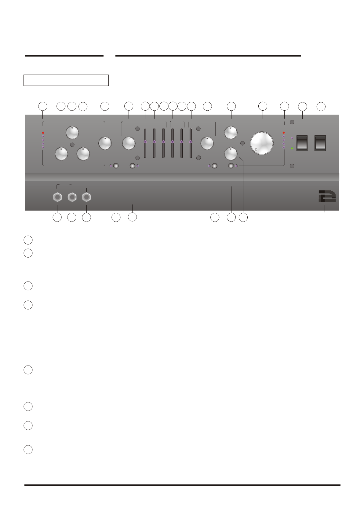
B1-2-3 Front Panel
6
5
4
7
8
12
11 17
14 15
13
16
33
18
22
23
24
25
26
1
2
4
Eq Defeat
3
Compression
5
4
6
3
2
1
10
0
Level
-
+
0
1
1
2
3
4
5
5
Volume
7
4
8
3
9
2
1
2
3
0
4
Output
5
6
7
8
9
10
Run
Standby
Laney
Input
2
3
1
Passive
Fet Gain
5
4
6
7
3
8
9
Output
4
0
5
Tuner
6
10
7
8
9
Preamp Mix
50/50
Fet
Tube
Bright
2
1
10
0
Drive
5
4
6
7
3
8
2
9
1
10
0
Tube
Input
Active
Bass
- -
+ +
0 0
1
1
2
2
3
3
4
4
5 5
5
Preshape
Mid
Lo
Mid
Hi Hi
Lo
EQ
Treble
1
2
3
4
5
Pres
B1B1
2
1
Passive Input: High impedance input for instruments with normal output i.e. lower output level.
1
2
Active Input: Low impedance input with half the input sensitivity of the passive input for instruments with an active circuitry and
3 9
10
19
21
20
high output levels. As there are so many different output levels from so many types of instruments available, you should try both
sockets before making a decision. Players using floor-mounted effects may also benefit from using the input to avoid unduly
overloading the pre amp.
3
Tuner: Socket provided for connecting an external tuner. Using this socket in conjunction with the Stand by switch (25)switched to
stand-by allows silent tuning.
Model number
Power
1
0
4
Input Level Indicators: The LED indicators give you a visual indication of the level of signal present in the pre amp. The level of
signal is determined by the positions of the FET gain control (6) and the tube output control (5+7). The signal indicated by the LED's
has its source directly before the master volume control (23) and after all the EQ options and FX loops. The reason for this is
straightforward - variations in EQ and external effects levels can have a dramatic effect upon the level of signal running through the pre
amp. Indicating the level of signal present in the pre amp before the EQ and FX loop facilities would not give you a realistic indication
of the level passing through the pre amp and into the power amp sections. Giving rise to the possibility of unwanted input distortion
from levels running to high. The ideal level should be set so that the red LED is activated only during the most aggressive playing
section. This assures that the pre amp is running at its optimum performance level and assures that a sufficient level of signal is present
at the send of the FX loop (38-40) and capable of driving any outboard processing equipment connected to this socket.
5
Drive: This control sets the level of tube drive applied to the onboard ECC83 tube. When used in conjunction with the tube output
control (7) the onboard tube can be used to generate anything from a warm tube sound through to a heavily distorted fuzz bass. For a
clean warm tube sound the control should be set around 4-5. At this point it should be noted that the position of the Preamp Mix control
(8)will have a fundamental effect upon the sound heard - see section eight. For a more dramatically distorted valve sound, simply dial in
more valve drive and adjust the output (7) as required.
6
Fet Gain: This control sets the level of FET gain to the pre amp signal. FET gain produces a clean wide bandwidth signal. As in the
Drive section above, the position of the Preamp Mix control (8) will have a fundamental effect upon the sound heard - see section eight.
Tube Output: This control sets the overall level of the tube stage and should be set to the desired volume level- say 5. At this point it
7
should be noted that the position of the Preamp Mix control (8) will have a fundamental effect upon the sound heard - see section eight.
For a more dramatically distorted valve sound, simply dial in more valve drive and adjust the output as required.
Preamp Mix: This control sets the mix of input signal type routed through the pre amp. It can be set to route either the signal from
8
the FET stage or the signal from the TUBE stage - or any combination of either of these signals. In order to get a true 50/50 mix the
following procedure should be followed. Select full FET on the mix control - set the FET stage to the desired level. Turn the mix
control to full tube - set the desired drive and output level to the same level as the FET channel - there is now a true 50/50 signal mix
B series MANUAL
Page 5

Laney
Bright Switch: The bright switch allows the user to boost the whole frequency response of the pre amplifier from mid range upward
9
by 6db. This allows the player to mimic plugging into the bright channel on an old style tube bass amplifier.
Pre Shape: This allows a pre determined EQ curve to be applied to the pre amp signal. The EQ curve represents a cut of signal
10
between 300 - 400 Hz, a boost at 70hz and a boost from 1 - 2.5 kHz. The pre shape can also be augmented by the other controls in the
EQ section (9 - 18)This feature is footswitchable via the FS5 footswitch allowing the user to switch the preshape in and out whilst
playing.
Bass Control: This is a shelving response control with maximum lift and cut at 40Hz
11
Lo Bass Slider: This allows the user to set the level of low bass, around 40 Hz. This portion of the sonic spectrum is associated with
12
the physical feel of playing bass. Should be used to tailor the amplifier response to instrument which are either detuned or feature an
additional low string.
Mid Bass Slider: This allows the user to set the level of MID bass, around 80 Hz.
13
Hi Bass Slider: This allows the user to set the level of HI bass, around 150 Hz. This frequency pocket is associated with the clarity
14
of a low bass signal. Experiment with cutting this frequency area in conjunction with boosting the LO and MID bass sliders for a real
low-end punch without it sounding to muffled or wooly.
Each of the bass sliders has a narrow frequency range to allow the user to effect only the area of the frequency range they require.
15
Lo Mid Slider: This slider effects a broad band of frequencies around 400Hz.
44
16
Hi Mid Slider: This slider effects frequencies around 800Hz.
17
Presence: This slider effects frequencies around 1KHz - 4 kHz.
18
Treble: This control effects the upper frequencies and peaks at 10KHz
EQ Defeat: This buttons allows the user to defeat the slider EQ section of the pre amplifier. This feature is footswitchable via the FS5
19
footswitch allowing the user to switch the slider EQ in and out whilst playing.
Compression Switch: This button allows the user to switch in the on board compressor. This feature is footswitchable via the
20
dedicated FS5 footswitch allowing the user to switch the compressor in and out whilst playing.
Compression Level: This control allows the user to set the Volume Level of the compressed signal. The compression level should
21
be used to set the desired balance between a signal with compression selected to that of a signal with compression defeated.
Compression: This control allows the user to set the amount of compression applied to the post pre amp signal. The compressors
22
main function is to allow the user to push more signal through the power amplifier at high continuous levels increasing the usable range
of the amplifier. It also enables any effects units connected to the B1/2/3 to be driven harder by removing unwanted signal peaks.
Setting the level of compression at 0 applies a minimal amount of compression, whilst set at 10 the maximum degree of compression.
In most instances the optimum level should be somewhere around 5 - 6. Since this feature is footswitchable via the FS5 footswitch. It
can also be utilized as a footswitchable volume boost for solo passages etc.
Volume: This control determines the over all listening volume of the unit.
23
Output LEDS: The output LEDS track the position of the volume control. The signal level indicated by the LEDS is derived from
24
immediately before the power amp output, so these LEDS indicate the signal level present in the power amp itself. It is worth
mentioning here that when the RED LED is illuminated the power amplifier is approaching its maximum undistorted output..
Standby Switch: The standby switch should be used to soft start the amplifier. Used in conjunction with the power switch (26)
25
when the amplifier is first turned on the standby switch should be in the standby position. This enables the preamp, but disables the
power amp, allowing the user to tune up silently and test the connections to external effect connected to the effects loop. Switching the
standby switch from standby to run allows signal to pass into the power amp and the amplifier is now ready to play. When switching
off the unit firstly switch the standby switch from run to standby and then switch the unit off via the power switch (26)
B series MANUAL
Page 6

Laney
Standby Switch: (Continued) The standby switch also functions as a reset switch should the unit experience faulty running
25
conditions caused by items such as incorrect cabinet impedance matching. For example, whilst the unit is capable of running into a
wide variety of loads, if the loads are extremely low (1 Ohm for example) for long periods of time the unit may shut down. The unit
will also shut down should it detect a fault in items such as cable etc. When the unit shuts down it has the same effect as switching
the standby switch, ie. it shuts down the output section. All the pre amp functions are still available, including any pre-amp out
connections, to a mixing desk etc. The front panel remains illuminated with the addition of the fact that both the blue and the green
LED associated with the standby switch are lit at the same time. In order to reset the amplifier flick the standby from run to standby
then back to run. Under most normal circumstance this will reset the amp. If this procedure does not reset the amplifier it may be
necessary to reset the amplifier by switching the unit off at the mains power supply and then back on again. Making sure the unit has
been switched to standby before powering down.
Power Switch: This switch should be used in conjunction with the standby switch to switch the unit on and off when required.
26
B1 Rear Panel - See P7 for B2/B3 differences
55
26a
Warning This equipment must be earthed.Warning This equipment must be earthed.
Power Consumption
Power Consumption
750Watts ~50-60Hz
750Watts ~50-60Hz
Supply VoltageSupply Voltage
~115V
~115V
230V
230V
~
~
CAUTIONCAUTION
RISK OF ELECTRIC SHOCK - DO NOT OPENRISK OF ELECTRIC SHOCK - DO NOT OPEN
Made in the United Kingdom by BLT Industries Ltd.Made in the United Kingdom by BLT Industries Ltd.
Avis
Risque de choc electrique - ne pas ouvrir.
Risque de choc electrique - ne pas ouvrir.
To reduce the risk of electric shock do not remove covers.
To reduce the risk of electric shock do not remove covers.
No user serviceable parts inside. Refer servicing to
No user serviceable parts inside. Refer servicing to
Debrancher le cordon d’alimentation
Debrancher le cordon d’alimentation
To reduce the risk of fire or electric shock do not
To reduce the risk of fire or electric shock do not
expose this appliance to rain or moisture.
expose this appliance to rain or moisture.
26a
27
Avis
Caution
Caution
qualified personnel only.
qualified personnel only.
Attention.
Attention.
avant toute intervention.
avant toute intervention.
Warning
Warning
Power input: Socket for connecting mains plug.
Reset Button: Should the unit be connected in error and experience a continuos overload situation such as connecting the unit to an
Push To ResetPush To Reset
!!
27
Bi-Amp/HiBi-Amp/Hi
Min Load
Min Load
2 Ohms
2 Ohms
BridgeBridge
Min Load
Min Load
2 Ohms
2 Ohms
Min Load
Min Load
2 Ohms
2 Ohms
Bi-Amp/LoBi-Amp/Lo
28
k
k
c
c
o
o
L
L
k
k
c
c
o
o
l
l
n
n
U
U
k
k
c
c
o
o
L
L
k
k
c
c
o
o
l
l
n
n
U
U
k
k
c
c
o
o
L
L
k
k
c
c
o
o
l
l
n
n
U
U
30
29
Active CrossoverActive Crossover
-0+-0+
11 11
31
22
33
44 44
55
32
33
34
Amp ModeAmp Mode
90
Dual MonoDual Mono
BridgeBridge
36
incorrect supply voltage or should the amplifier experience a catastrophic component failure then the reset button will trip. This will
cause the unit to completely shut down and all power to the amplifier will be removed. Once the unit has tripped the reset button needs
to be pushed in. If the unit fails to reset itself immediately then the amplifier should be looked at by a qualified technician. Consult your
dealer.
Amp1/Hi: Speaker connector for connecting external speaker cabinets. The type of signal present at this speaker connector varies,
28
depending upon the selected mode of operation for the power amplifier. When the amp mode selector is set to DUAL MONO this
speakon receives a 750-watt full range signal. When the amp mode is set to Bi amp, the onboard active cross over (31) comes into play.
In this situation the power amp signal is split into a Hi signal and a Lo signal. The Hi signal is sent to this speakon, the Lo signal is sent
to the Amp2/Lo speaker (30). The frequency of the active crossover is 150Hz, anything above 150 is sent to the Hi socket, anything
below is sent to the Lo socket. The level of the signal sent to the Hi socket is controlled by the active crossover level control; the output
to the Lo speaker remains fixed. When the amp mode selector is switched to Bridge this speakon should not be used..
22
33
5 5
LevelLevel
HiHi
LoLo
FootswitchFootswitch
Bi-ampBi-amp
Pre-Amp
Pre-Amp
Out
Out
SendSend
ReturnReturn
0dB0dB
-10dB-10dB
BypassBypass
Pre EqPre Eq
Post EqPost Eq
Aux
Aux
In
In
Effects
Effects
Loop
Loop
Direct
Direct
Inject
Inject
37
38
39
40
41
42
Bridge: This speaker socket should be used when the amp mode selector is switched to bridge, the remaining speaker connections
29
should not be used whilst running in bridge mode.. The minimum load for the bridge speakon is 4 Ohms. The output of the unit in
bridge mode is 1500 watts RMS. Bridge mode is ideal when you only have one cabinet
30
Amp2/Lo: Speaker connector for connecting external speaker cabinets. The type of signal present at this speaker connector varies,
depending upon the selected mode of operation for the power amplifier. When the amp mode selector is set to DUAL MONO this
speakon receives a 750-watt full range signal. When the amp mode is set to Bi amp, the onboard active cross over (31) comes into play.
In this situation the power amp signal is split into a Hi signal and a Lo signal. The Lo signal is sent to this speaker, the Hi signal is sent
to the Amp1/Hi speaker (28). The frequency of the active crossover is 150Hz, anything above 150 is sent to the Hi socket, anything
below is sent to the Lo socket. The level of the signal sent to Lo speaker is fixed. When the amp mode selector is switched to Bridge
this speakon should not be used.
B series MANUAL
Page 7

Laney
B1 Rear Panel - Continued
Active CrossoverActive Crossover
-0+-0+
11 11
22
31
32
33
34
90
36
33
44 44
55
Amp ModeAmp Mode
Dual MonoDual Mono
BridgeBridge
22
33
5 5
LevelLevel
HiHi
LoLo
FootswitchFootswitch
Bi-ampBi-amp
Pre-Amp
Pre-Amp
Out
Out
SendSend
ReturnReturn
0dB0dB
-10dB-10dB
BypassBypass
Pre EqPre Eq
Post EqPost Eq
AuxInAux
In
Effects
Effects
Loop
Loop
Direct
Direct
Inject
Inject
37
38
39
40
41
42
Active Crossover Level: This control sets the level of Hi signal sent to the Amp1/Hi
31
output speaker socket (28).along with the level of signal appearing at (32) It should be
used to balance the level of the high frequency cabinet, a 4 x 10 cabinet for example
against the level of the sub bass cabinet, say a 1 x 15", to get the desired sound.
Hi Socket: This socket should be used to supply a Hi frequency signal to an external
32
amplifier should additional sound reinforcement be required. It is worth mentioning here
that this feature is continually available and is not reliant on the amp mode being selected
to run in Bi amp mode.
Lo Socket: This socket should be used to supply a Lo frequency signal to an external
33
amplifier should additional sound reinforcement be required. It is worth mentioning here
that this feature is continually available and is not reliant on the amp mode being selected
to run in Bi amp mode.
Footswitch socket: 5 pin socket for connecting the dedicated FS5 footswitch to the
34
unit.
66
Power amp mode switch: This switch selects the mode of operation of the B1 power amplifier section (See P7 for B2/B3
35
description) Three modes of operation are available Dual Mono, Bi-amp and Bridge. In Dual Mono mode the two onboard power
amplifiers run in parallel supplying 750 watts RMS of full range signal to each of the two output connections (28,30). In Bi amp mode
the onboard active crossover splits the frequency response of the pre amplifier and sends any frequencies below 150Hz to one power
amplifier and anything above 150Hz to the remaining power amplifier. Each of the power amplifiers has a dedicated output. See (28,
30) in Bridge mode both individual power amplifier sections operate together producing 1500watts RMS of full range signal.
Preamp out: This socket provides a line level pre amp out signal. Can be used to slave two B1/B2/B3’s together using the second B1’s
36
aux in socket (37)
Aux in: The Auxiliary input socket allows the user to connect external devices into the B1/B2/B3 bypassing the pre amp. The user can
37
also connect external sound devices such as CD & Mds or drum machines. The Aux socket is a mono socket, so stereo playback from
any device will not be heard.
Effect Loop Send: Socket provided for connecting external effects processors to the B1/B2/B3. The send to the effects loop should be
38
connected to the input of the effects processor. All connections should be made using high quality instrument cable
Effects Loop Mode Selector: The effects loop can be run in three different modes depending upon the needs of the player. For
39
connecting to studio style rack processors the FX loop should be run at a level of 0dB, for connecting floor mounted effects such as old
analog pedals the fx loop should be run at -10dB. In Bypass mode all effects loop sockets, both send and return are isolated from the
signal path. The effects loop on the B1/B2/B3 is run in an insert mode, affecting 100% of the amplifier signal.
40
Effects Loop Return: This socket is provided for connecting the return of an external processor to the B1/B2/B3. The output of the
external effects processor should be connected to the effects loop return on the B1/B2/B3. All connections should be made using high
quality instrument cable
41
DI Pre EQ/Post EQ Selector: This allow the player to select the origin of the signal sent as a Direct Inject output to an external
device such as a mixing desk, recording device or an additional power amplifier.
The user can obtain a signal from two distinct sources Pre EQ i.e. directly after the pre amp mix control, and before any onboard EQ has
been applied or Post EQ i.e. directly before the volume control after all EQ as well as any effects connected to the B1/B2/B3 have been
applied to the signal. The DI signal from the B1/B2/B3 is an electronically balanced signal.
DI XLR Output: The XLR socket is provided for connecting the B1/B2/B3’s electronically balanced DI signal to an external device
42
such as a mixing desk, recording device or an additional power amplifier.
B series MANUAL
Page 8

Laney
B2/B3 Rear Panel
77
Internal/HiInternal/Hi
Sub/LoSub/Lo
91
Active CrossoverActive Crossover
-0+-0+
11 11
31
22
33
44 44
55
32
33
34
Amp ModeAmp Mode
90
Internal+SubInternal+Sub
Internal OnlyInternal Only
36
26
Warning This equipment must be earthed.Warning This equipment must be earthed.
Power Consumption
Power Consumption
750Watts ~50-60Hz
750Watts ~50-60Hz
Supply VoltageSupply Voltage
~115V
~115V
230V
230V
~
~
CAUTIONCAUTION
RISK OF ELECTRIC SHOCK - DO NOT OPENRISK OF ELECTRIC SHOCK - DO NOT OPEN
Made in the United Kingdom by BLT Industries Ltd.Made in the United Kingdom by BLT Industries Ltd.
Avis
Risque de choc electrique - ne pas ouvrir.
Risque de choc electrique - ne pas ouvrir.
To reduce the risk of electric shock do not remove covers.
To reduce the risk of electric shock do not remove covers.
No user serviceable parts inside. Refer servicing to
No user serviceable parts inside. Refer servicing to
Debrancher le cordon d’alimentation
Debrancher le cordon d’alimentation
To reduce the risk of fire or electric shock do not
To reduce the risk of fire or electric shock do not
expose this appliance to rain or moisture.
expose this appliance to rain or moisture.
Internal/Hi: Speaker connector to the two internal 10“ loudspeakers. The type of signal present at this speaker connector varies,
90
Avis
Caution
Caution
qualified personnel only.
qualified personnel only.
Attention.
Attention.
avant toute intervention.
avant toute intervention.
Warning
Warning
Push To ResetPush To Reset
!!
27
Bi-Amp/HiBi-Amp/Hi
Min Load
Min Load
2 Ohms
2 Ohms
Min Load
Min Load
2 Ohms
2 Ohms
Bi-Amp/LoBi-Amp/Lo
90
k
k
c
c
o
o
L
L
k
k
c
c
o
o
l
l
n
n
U
U
k
k
c
c
o
o
L
L
k
k
c
c
o
o
l
l
n
n
U
U
depending upon the selected mode of operation for the power amplifier. When the amp mode selector is set to Internal+Sub, this
speakon receives a full range signal. When the amp mode is set to Bi amp, the onboard active cross over (31) sends only the Hi
frequency content to this speakon, the Lo signal is sent to the Sub/Lo connector(30). The frequency of the active crossover is 150Hz,
anything above 150Hz is sent to the this socket, anything below is sent to the Sub/Lo socket. The level of the signal sent to the Hi
socket is controlled by the active crossover level control allowing the desired balance of sound to be obtained ; the output to the Lo
speaker remains fixed. .
Sub/Lo: Speaker connector for connecting external Sub cabinets on the B2, or the internal Sub loudspeaker on the B3. The type of
91
signal present at this speaker connector varies, depending upon the selected mode of operation for the power amplifier. When the amp
mode selector is set to Internal+Sub, this speakon receives a full range signal. When the amp mode is set to Bi amp, the Lo frequency
signal is sent to this speaker, the Hi signal is sent to the Internal/Hi socket (90). The frequency of the active crossover is 150Hz,
anything above 150 is sent to the Hi socket, anything below is sent to the Lo socket. The level of the signal sent to Lo speaker is fixed.
When the amp mode selector is switched to Bridge this speakon should not be used.
Power amp mode switch: This switch selects the mode of operation of the B2/B3 power amplifier section. Three modes of
92
operation are available Internal+Sub, Bi-Amp, and Internal only.
-In Internal+Sub mode the two onboard power amplifiers run in parallel supplying 750 watts RMS of full range signal to each of the two
output connections (90) feeds the two 10“ loudspeakers and (91) supplies the single 15” loudspeaker on the B3 or is used for connection
of an external cabinet on the B2.
-In Bi amp mode the onboard active crossover splits the frequency response of the pre amplifier and sends any frequencies below
150Hz to the (15“ Sub loudspeaker (B3 only) or (91) on the B2 model) and anything above 150Hz to the two 10” loudspeakers.
-In Internal only mode, Only the two 10“ loudspeakers are used. No signal appears on the Sub/Lo connector.
22
33
5 5
LevelLevel
HiHi
LoLo
FootswitchFootswitch
Bi-ampBi-amp
Pre-Amp
Pre-Amp
Out
Out
SendSend
ReturnReturn
0dB0dB
-10dB-10dB
BypassBypass
Pre EqPre Eq
Post EqPost Eq
Aux
Aux
In
In
Effects
Effects
Loop
Loop
Direct
Direct
Inject
Inject
37
38
39
40
41
42
Descriptions for all other functions on the B2/B3 rear are identical to those listed on previous pages for B1 rear layout.
Cabinet connections.
Part Number 005083 Part Number 005083
Model
Operation
Model
B2B2
T
R
U
I
E
K
N
InternalInternal
B2
B2
B2+Sub
B2+Sub
B2+Sub
B2+Sub
Model
Model
Operation
Full Range
Full Range
Full Range
Full Range
Bi-Amp (Xover)
Bi-Amp (Xover)
Operation
Operation
83
81
Horn on/off: Enables or disables the onboard HF horn.
82
Horn Hi/Lo: Reduces the output level from the horn.
83
Internal: Connection to the internal two 10“ loudspeakers.
84
Sub: Connection to the internal 15“ sub loudspeaker
84
Information: Mode switch selection details.
Amp Mode Switch
Amp Mode Switch
Internal Only
Internal Only
Internal+Sub
Internal+Sub
Bi-Amp
Bi-Amp
Amp Mode Switch
Amp Mode Switch
85
HornHorn
OffOff
OnOn
HornHorn
81
B3B3
Hi
Lo
82
T
R
U
I
E
K
N
SubSub
84
InternalInternal
Model
Operation
Model
Operation
B3
Full Range
B3
T
R
U
E
N
Full Range
I
K
B3
Bi-Amp (Xover)
B3
Bi-Amp (Xover)
Model
Operation
Model
Operation
Amp Mode Switch
Amp Mode Switch
Internal+Sub
Internal+Sub
Bi-Amp
Bi-Amp
Amp Mode Switch
Amp Mode Switch
85
Note: On the B2 when used without an extension speaker, Set mode (90) to ‘Internal Only’
B series MANUAL
Part Number 005084 Part Number 005084
HornHorn
OffOff
OnOn
Hi
Lo
HornHorn
81
8283
Page 9

Laney
Specifications
Input Sensitivity: Active -18dBu (90mV) 1M Ohm
(Fet Channel) Passive -13dBu (150mV) 150K Ohm
Input Sensitivity: Active -46dBu (4mV) 1M Ohm
(Tube Channel) Passive -40dBu (10mV) 150K Ohm
Tuner: Input level -6dBu
DI Output: XLR balanced Pre/Post EQ (0dBu)
Axillary input: -15dBu (145mV) 10K Ohm
Lo Pass output: +4dBu (1.2V) Xover 150Hz
Hi Pass output: +4dBu (1.2V) Variable +- 6dBu Xover 150Hz
Power output: 2x750Watts into 2ohms
2x550Watts into 4ohms
2x350Watts into 8ohms
1x1500Watts into 4ohms*
1x1000Watts into 8ohms*
*Bridge operation
88
Distortion: THD Typically<0.03%
IMD Typically<0.03%
Protection: Short circuit, Open circuit, Load mismatch and DC
Supply Voltage: 230V 50/60Hz (Factory set option)
115V 50/60Hz (Factory set option)
Power Consumption: Typically 350Watts average
1800Watts Peak.
Typical wiring to an NL2 Speakon connector.
1+
1-
-
+
™
Speakon Trademark of Neutrik AG
B series MANUAL
Page 10

Laney
Laney
System DiagramSystem Diagram
99
B series MANUALB series MANUAL
Page 11

BLT Industries Ltd.,
Newlyn Road,
Cradley Heath,
West Midlands.
B64 6BE.
Tel: (0044) (0)1384 633821
Fax: (0044) (0)1384 639186
Http://www.laney.co.uk
In the interest of continued product development BLT Industries Ltd. Reserves the
right to amend product specification wihtout prior notification.
 Loading...