

Page 1
OWNER’S HANDBOOK
Publication Part No. LRL 10 02 51 702
Page 2

About this handbook
This handbook forms part of the Owner literature supplied with your new vehicle. Left-hand drive
and right-hand drive conditions may be shown in the graphics and where information is specific to
a particular country, it is indicated as such.
The Quick start section is designed to rapidly familiarise the driver with the initial set up and also
explain some of the unique features. Please take the time to study the operating instructions with
your vehicle as soon as you can.
Important
The information contained in this handbook covers all vehicle derivatives and optional equipment.
Some of the options may not be fitted to your vehicle unless they formed part of the original vehicle
specification. Therefore some parts of this handbook may not apply to your vehicle. Furthermore,
due to printing cycles, it may include descriptions of options before they become generally
available.
The information contained in this publication was correct when it went to print. Vehicle design
changes may have been made after this handbook was printed. When this occurs a handbook
supplement is added to the literature pack. Subsequent updates can be viewed on the Land Rover
Internet site at; www.ownerinfo.landrover.com.
In the interest of development, the right is reserved to change specifications, design or equipment
at any time without notice and without incurring any obligations. This publication, or part thereof,
may not be reproduced nor translated without our approval. Errors and omissions excepted.
© Land Rover 2007
All rights reserved.
Published by Land Rover Technical Communications.
2
Page 3

Contents
Quick start
QUICK START ................................................... 7
Filling station information
FILLING STATION INFORMATION................... 24
Introduction
SYMBOLS GLOSSARY .................................... 26
LABEL LOCATIONS ......................................... 26
HEALTH AND SAFETY..................................... 27
DATA RECORDING.......................................... 27
PARTS AND ACCESSORIES............................ 28
Keys and remote controls
USING THE KEY .............................................. 30
GENERAL INFORMATION ON RADIO
FREQUENCIES ................................................ 30
USING THE REMOTE CONTROL ..................... 31
Locks
LOCKING AND UNLOCKING............................ 33
Alarm
ARMING THE ALARM ..................................... 35
DISARMING THE ALARM ............................... 36
Seats
SITTING IN THE CORRECT POSITION ............ 38
MANUAL SEATS ............................................. 39
HEAD RESTRAINTS ........................................ 41
REAR SEATS................................................... 41
HEATED SEATS............................................... 45
Seat belts
PRINCIPLE OF OPERATION ............................ 46
FASTENING THE SEAT BELTS ........................ 47
USING SEAT BELTS DURING PREGNANCY.... 48
Child safety
CHILD SEATS.................................................. 49
BOOSTER CUSHIONS ..................................... 50
CHILD SAFETY LOCKS.................................... 50
Lighting
LIGHTING CONTROL ...................................... 51
REAR FOG LAMPS.......................................... 51
HEADLAMP LEVELLING ................................. 52
HAZARD WARNING FLASHERS...................... 52
DIRECTION INDICATORS ............................... 53
INTERIOR LAMPS .......................................... 53
CHANGING A BULB ........................................ 53
BULB SPECIFICATION CHART ........................ 59
Wipers and washers
WINDSCREEN WIPERS .................................. 60
WINDSCREEN WASHERS............................... 60
REAR WINDOW WIPER AND WASHERS........ 61
ADJUSTING THE WINDSCREEN WASHER JETS .
61
CHECKING THE WIPER BLADES .................... 62
CHANGING THE WIPER BLADES.................... 62
Windows and mirrors
ELECTRIC WINDOWS ..................................... 63
SLIDING WINDOWS ....................................... 63
EXTERIOR MIRRORS ..................................... 64
INTERIOR MIRROR ........................................ 64
Instruments
INSTRUMENT PANEL OVERVIEW .................. 65
WARNING LAMPS AND INDICATORS ............ 67
Climate control
AIR VENTS ..................................................... 70
MANUAL CLIMATE CONTROL ........................ 71
SUNROOF ....................................................... 72
Convenience features
SUN VISORS .................................................. 74
CLOCK ............................................................ 74
CIGAR LIGHTER ............................................. 74
ASHTRAY ....................................................... 75
CUP HOLDERS ............................................... 75
STORAGE COMPARTMENTS .......................... 76
STEPS ............................................................ 76
Detachable roof
FITTING THE ROOF......................................... 77
3
Page 4

Contents
Starting the engine
STARTING A DIESEL ENGINE......................... 80
Transmission
MANUAL TRANSMISSION.............................. 81
TRANSFER GEARBOX..................................... 81
TECHNICAL SPECIFICATIONS ........................ 84
Brakes
PRINCIPLE OF OPERATION ............................ 85
HINTS ON DRIVING WITH ABS ...................... 85
PARKING BRAKE ............................................ 86
Driving hints
RUNNING-IN .................................................. 88
ECONOMICAL DRIVING.................................. 88
Fuel and refuelling
SAFETY PRECAUTIONS .................................. 89
FUEL QUALITY ............................................... 89
RUNNING OUT OF FUEL ................................. 89
REFUELLING .................................................. 90
TECHNICAL SPECIFICATIONS ........................ 91
Load carrying
GENERAL INFORMATION ............................... 92
LUGGAGE ANCHOR POINTS .......................... 92
ROOF RACKS AND LOAD CARRIERS ............. 93
Towing
TOWING A TRAILER ....................................... 94
LEVELLING ..................................................... 94
RECOMMENDED TOWING WEIGHTS ............. 95
ESSENTIAL TOWING CHECKS ........................ 95
TOW BAR ....................................................... 96
Maintenance
GENERAL INFORMATION.............................. 101
OPENING AND CLOSING THE BONNET......... 104
ENGINE COMPARTMENT OVERVIEW ........... 105
ENGINE OIL CHECK....................................... 107
ENGINE COOLANT CHECK ............................ 108
POWER STEERING FLUID CHECK................. 110
BRAKE FLUID CHECK .................................... 111
CLUTCH FLUID CHECK.................................. 112
WASHER FLUID CHECK ................................ 113
TECHNICAL SPECIFICATIONS....................... 114
Vehicle battery
BATTERY WARNING SYMBOLS.................... 115
BATTERY CARE............................................. 115
USING BOOSTER CABLES ............................ 117
CHARGING THE VEHICLE BATTERY ............. 118
CHANGING THE VEHICLE BATTERY ............. 119
Wheels and tyres
GENERAL INFORMATION.............................. 121
TYRE CARE ................................................... 123
USING WINTER TYRES ................................. 128
CHANGING A ROAD WHEEL ......................... 128
USING SNOW CHAINS .................................. 135
TYRE GLOSSARY .......................................... 135
TECHNICAL SPECIFICATIONS....................... 136
Fuses
CHANGING A FUSE ....................................... 137
FUSE BOX LOCATIONS ................................. 137
FUSE SPECIFICATION CHART ....................... 138
Emergency equipment
HAZARD WARNING FLASHERS .................... 141
Vehicle care
CLEANING THE EXTERIOR ............................. 98
CLEANING THE INTERIOR.............................. 99
REPAIRING MINOR PAINT DAMAGE............ 100
Status after a collision
DRIVING AFTER A COLLISION...................... 142
INSPECTING SAFETY SYSTEM COMPONENTS....
142
Vehicle recovery
TOWING POINTS........................................... 143
LASHING POINTS ......................................... 143
TRANSPORTING THE VEHICLE..................... 143
TOWING THE VEHICLE ON FOUR WHEELS... 143
4
Page 5

Contents
Vehicle identification
VEHICLE IDENTIFICATION PLATE................. 145
VEHICLE IDENTIFICATION NUMBER (VIN)... 145
Technical specifications
ENGINE SPECIFICATIONS ............................. 146
WEIGHTS ...................................................... 146
DIMENSIONS ................................................ 148
Type approvals
TYPE APPROVALS........................................ 151
Audio introduction
RADIO RECEPTION ....................................... 153
Audio unit overview
AUDIO UNIT OVERVIEW ............................... 154
Audio system security
SECURITY CODE........................................... 156
Audio unit operation
ON/OFF BUTTON ........................................... 157
VOLUME CONTROL ...................................... 157
AUDIO CONTROL .......................................... 157
WAVEBAND BUTTON .................................... 159
AUTOSTORE CONTROL ................................ 160
STATION PRESET BUTTONS ........................ 160
TRAFFIC INFORMATION CONTROL .............. 161
Compact disc player
LOADING COMPACT DISCS .......................... 162
EJECTING COMPACT DISCS......................... 163
COMPACT DISC PLAYBACK ......................... 164
TRACK SELECTION ....................................... 164
COMPACT DISC PAUSE................................ 164
FAST FORWARD/REVERSE........................... 165
RANDOM TRACK SELECTION....................... 165
REPEAT COMPACT DISC TRACKS................ 165
COMPACT DISC TRACK SCANNING ............. 165
MP3 FILE PLAYBACK.................................... 166
Auxiliary input (AUX IN) socket
AUXILIARY INPUT SOCKET .......................... 168
5
Page 6

6
Page 7
Quick start
Quick start
QUICK START
Keys and remote control
E85174
Always keep a remote control on the same key
ring as a starter and door lock key (black key);
the engine immobiliser detects the remote
control near the starter switch. Never attach
both remote controls to the same key ring. The
small metal key opens the fuel filler cap.
Vehicles with central door locking
Using the remote control
• Press the lock (PADLOCK symbol) button
once to lock all doors, immobilise the
engine and arm the alarm. The direction
indicators flash three times to confirm.
• Press the unlock (PLAIN) button once to
disarm the alarm and unlock all doors. The
direction indicators flash once and the
interior lamps illuminate.
Using the key
• Insert the key into the driver's door lock
and turn towards the rear of the vehicle to
lock all doors, immobilise the engine and
arm the alarm.
• Unlocking with the key is not
recommended; the alarm may not disarm
(depending on the vehicle specification).
Vehicles without central door locking
Locking and unlocking
• Each door must be locked or unlocked
individually. The remote control will not
operate the door locks.
• Turn the key towards the rear of the vehicle
to lock or towards the front to unlock.
Arming and disarming the alarm
• Press the lock (PADLOCK symbol) button
once to immobilise the engine and arm the
alarm. The direction indicators flash three
times to confirm.
• Press the unlock (PLAIN) button once to
disarm the alarm. The direction indicators
flash once and the interior lamps
illuminate.
7
Page 8
Quick start
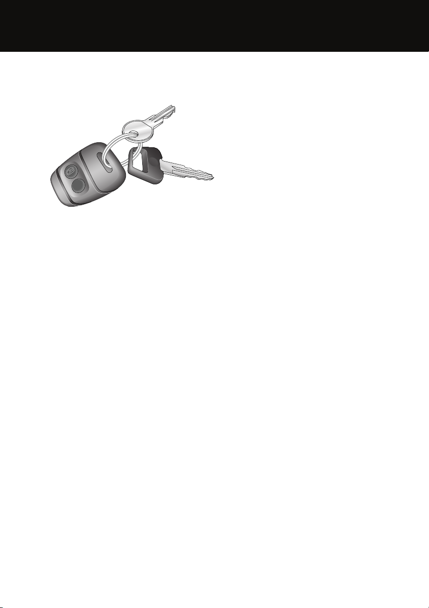
Pickup tailgate
E86246
To latch the tailgate, lift the gate from the
horizontal and locate over both latch plates as
shown. Pivot the latch plates upwards until
vertical and slide down to secure the tailgate.
To lower the tailgate, reverse the above
procedure, taking care when lowering the
tailgate.
The tailgate is not a load-bearing surface.
Engine starting and stopping
E85232
Starting the engine
1. Insert the starter key, turn the switch to
position II and wait until the glow plug
warning indicator goes out.
2. Fully depress the clutch pedal and turn the
key to position III to operate the starter
motor (do not press the accelerator pedal).
Release the key as soon as the engine
starts.
3. Do not run the engine above idle speed
until the oil pressure warning indicator
extinguishes.
4. If the engine stalls or fails to start, return
the key to position I before attempting to
restart.
Operating note
If the engine fails to start, continued use of the
starter motor may result in unburnt fuel
damaging the catalytic converter. Switch off
(position I) and wait 10 seconds before
attempting to restart.
Stopping the engine
• Always allow the engine to idle for 10
seconds before switching off.
8
Page 9
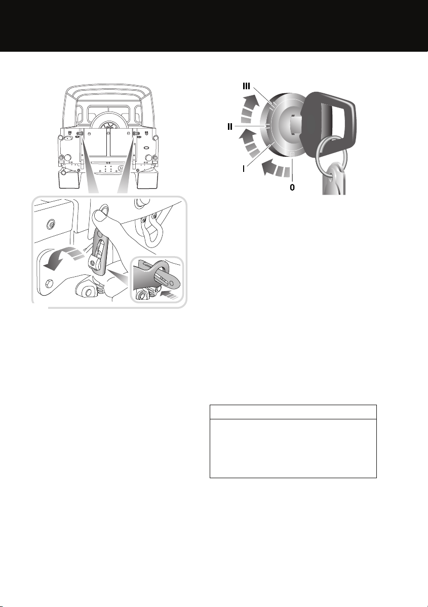
Front seats
1
Quick start
3
1
2
2
E85185
1. Forward/backward adjustment.
2. Backrest adjustment.
3. Head restraint height adjustment.
9
Page 10
Quick start
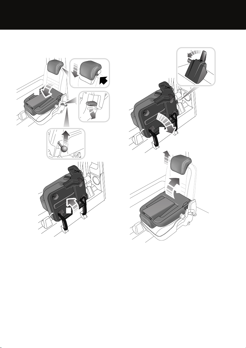
Third-row seats
Folding and stowing
2
Unfolding
1
1
2
3
1
3
2
3
E85190
1. Lower the head restraint.
2. Push the seat backrest locking catch
downwards to release. Fold the backrest
onto the seat cushion.
3. Pull the seat base locking lever upwards to
unlock, then fold the seat upwards towards
the side of the vehicle until the retaining
catch engages.
E85192
1. Move the release lever inwards and lower
the seat base into position.
2. Unfold the seat back, ensuring that the
catch engages.
3. Adjust the head restraint to the correct
position.
10
Page 11
Quick start
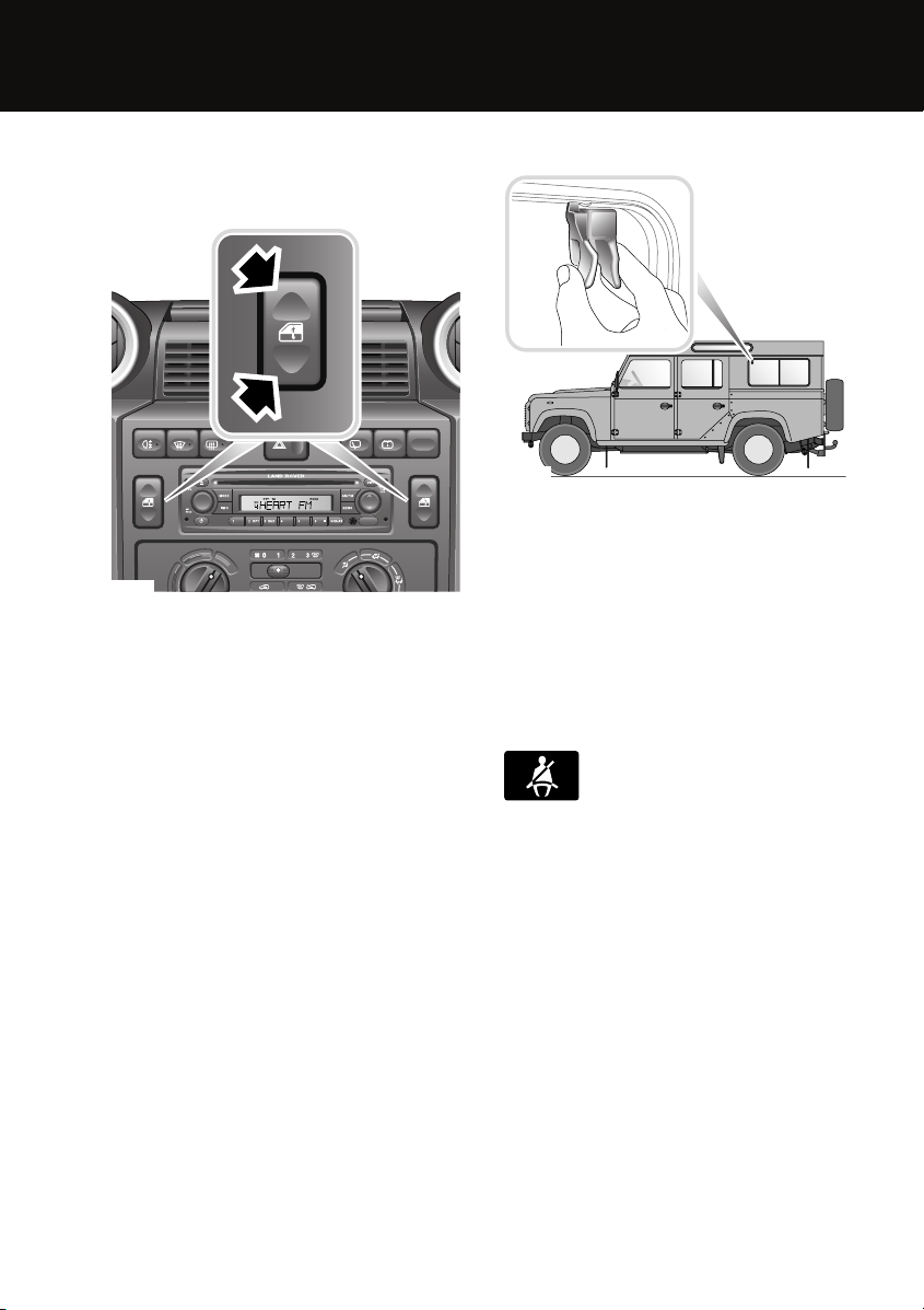
Windows
Front electric windows
E85218
• To open a window, press and hold the
bottom of the respective switch.
• To close the window, press and hold the
top of the switch.
Window movement can be stopped at any time
by releasing the switch.
Rear sliding windows
E85219
Squeeze the catch and slide the window to the
desired position. Release the catch making
sure that it locates securely in the sockets,
locking the window in position.
Seat belts and Child restraints
The use of front and rear seat belts is
mandatory in most countries. Using seat belts
saves lives. They should be worn by all
occupants whenever the vehicle is in use.
A warning indicator on the
instrument pack will illuminate to
alert you that the driver's seat belt is
unbuckled.
Child seats
It is important to remember that the child's
weight, rather than age, determines the type of
seat that is required. See CHILD SEATS
(page 49).
11
Page 12
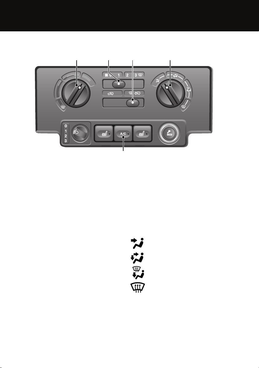
Climate control
Quick start
1 42 3
E85225
1. Temperature
2. Blower
3. Recirculation
4. Air distribution
5. Air conditioning
Temperature selection 1
Rotate the control to adjust the temperature of
the air entering the passenger compartment.
Blower speed 2
Slide the blower control to adjust airflow
through the vents.
Note: The blower will be switched on
automatically, if air conditioning is selected
when the blower is set to 0.
Air recirculation 3
Slide the lever to the left or right for
recirculated or fresh air.
5
Air distribution 4
Rotate the control to direct air flow from the
vents as required.
Face level vents
Foot and face level vents
Front screen and foot level vents
Front screen and side window vents
12
Page 13
Quick start
Air conditioning 5
Press button to switch the air conditioning on.
Press again to switch off.
Air conditioning is an integral part of the
heating and ventilation system, providing
cooled and dehumidified air for occupant
comfort. The dry airflow is effective in
preventing misting of windows and is also
beneficial at low external temperatures.
External water deposits
The air conditioning system removes
moisture from the air and deposits excess
water beneath the vehicle. Puddles may form,
but this is no cause for concern.
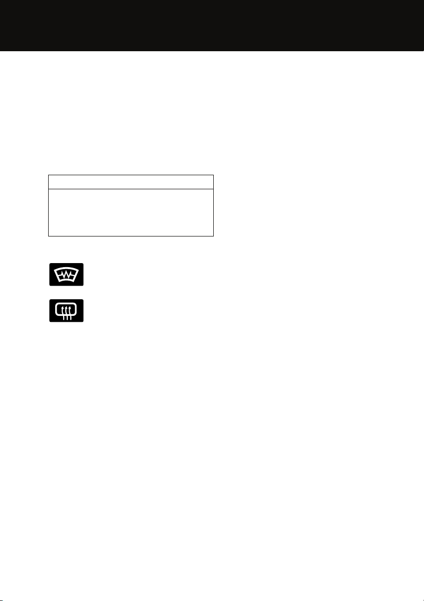
Heated screens
Press to operate. An LED in the
switch will illuminate when
operating.
The heaters will automatically
switch off after a preset interval.
13
Page 14
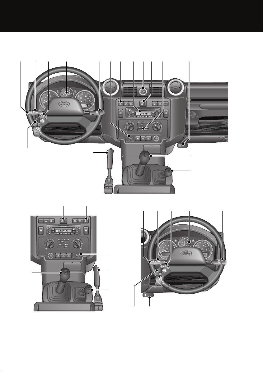
Facia
1 2 3
Quick start
4 5 7 8 9
0
6
11 12
10
E86251
16
13
10
15
7
6
15
14
13
14
1 2 3 4 5
0
16 12
14
Page 15

1. Direction indicator switch
2. Headlamp high or low beam switch
3. Main lighting switch
4. Instrument pack
5. Washer/wiper switch
6. Headlamp levelling switch
7. Rear fog lamp switch
8. Audio unit
9. Clock
10. Hazard warning switch
11. Heater/air conditioning controls
12. Bonnet release handle
13. Gear lever
14. Transfer gearbox lever
15. Parking brake
16. Starter switch
Quick start
15
Page 16
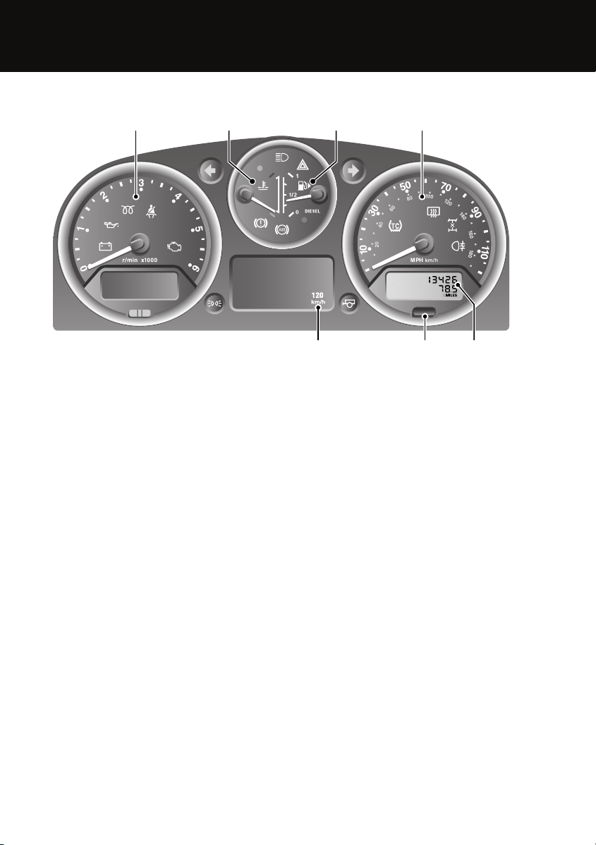
Instrument pack
Quick start
1 2 3 4
E86248
1. Tachometer
2. Temperature gauge
3. Fuel gauge
4. Speedometer
5. Total distance (odometer) and trip recorder
6. Trip recorder reset button
7. Overspeed warning indicator
7
56
16
Page 17
Quick start
Tachometer
Indicates engine speed in revolutions per
minute (x 1 000). In normal driving conditions
the engine is most fuel efficient between 2 000
and 3 000 rev/min.
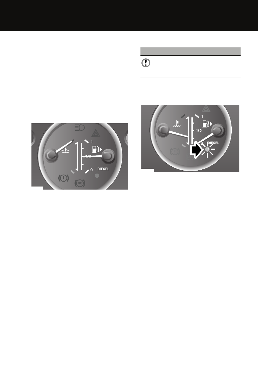
Temperature gauge
At normal operating temperature, the pointer is
positioned approximately midway between the
red and blue markers on the gauge (the precise
position will vary according to climatic
conditions).
E86249
If the pointer moves above the midpoint, the
engine coolant is becoming too hot. Should the
pointer move to the top of the scale, severe
engine damage could occur (under these
circumstances the air conditioning may switch
off and engine performance may reduce to
minimise engine load).
Stop the vehicle as soon as safety permits, and
allow the engine to idle until the pointer moves
back to its normal position. If the problem
persists, seek qualified assistance
immediately.
Fuel gauge
CAUTION
Never allow your vehicle to run out of
fuel, as the resultant misfire may destroy
the catalytic converter.
When the starter switch is at position II the
pointer quickly rises to show the level of fuel in
the tank.
E85159
When the amber low fuel warning indicator
(arrowed) illuminates, there is approximately 9
litres (2 gallons) of fuel in the tank. The small
arrow alongside the fuel pump symbol
indicates the side of the vehicle on which the
fuel filler is located.
Total distance (odometer) and trip recorder
Indicates the total distance travelled, and also
shows the most recent individual journey
distance.
Trip recorder reset switch
With the starter switch turned on, press to
reset the trip recorder back to zero.
17
Page 18
Quick start
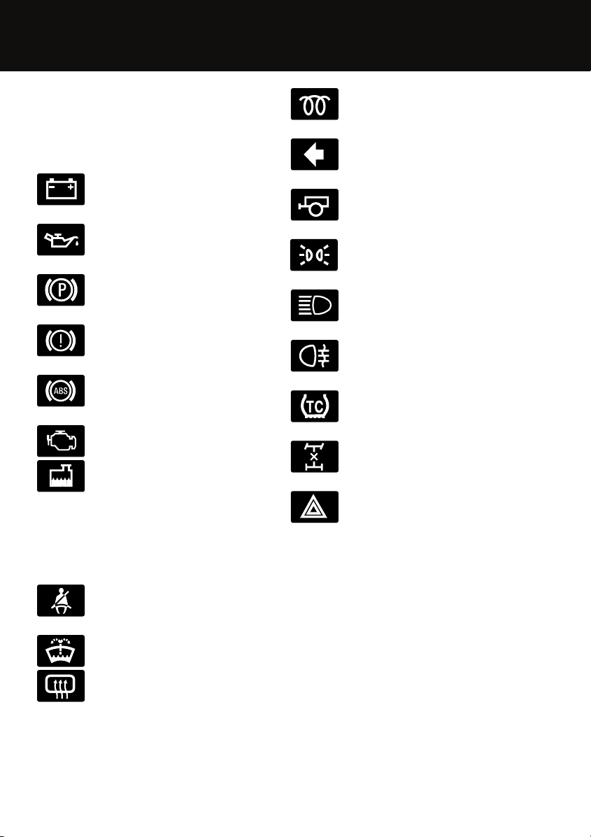
Warning indicators (attention)
If any of the following illuminate when driving,
a fault has been detected. Refer to the
individual pages given below for further
information.
Battery charge indicator. See
WARNING LAMPS AND
INDICATORS (page 67).
Low oil pressure. See WARNING
LAMPS AND INDICATORS
(page 67).
Parking brake. See WARNING
LAMPS AND INDICATORS
(page 67).
Brake systems. See WARNING
LAMPS AND INDICATORS
(page 67).
Anti-lock braking system. See
WARNING LAMPS AND
INDICATORS (page 67).
Engine. See WARNING LAMPS
AND INDICATORS (page 67).
Low engine coolant level. See
ENGINE COOLANT CHECK
(page 108).
Warning indicators (information)
The following will illuminate during normal
driving to indicate that a particular system or
feature is operating.
Seat belt reminder. See WARNING
LAMPS AND INDICATORS
(page 67).
Low screen washer level. See
WASHER FLUID CHECK (page 113).
Heated rear screen on. See
WARNING LAMPS AND
INDICATORS (page 67).
Diesel glow plugs active. See
WARNING LAMPS AND
INDICATORS (page 67).
Direction indicator. See WARNING
LAMPS AND INDICATORS
(page 67).
Trailer direction indicator. See
WARNING LAMPS AND
INDICATORS (page 67).
Side lamps on. See WARNING
LAMPS AND INDICATORS
(page 67).
Headlamp high beam on. See
WARNING LAMPS AND
INDICATORS (page 67).
Rear fog lamps on. See WARNING
LAMPS AND INDICATORS
(page 67).
Traction control on. See WARNING
LAMPS AND INDICATORS
(page 67).
Differential lock engaged. See
WARNING LAMPS AND
INDICATORS (page 67).
Hazard warning lamps on. See
WARNING LAMPS AND
INDICATORS (page 67).
18
Page 19

Quick start
Parking brake
The vehicle may move slightly when the
parking brake is applied. This is because the
parking brake operates on the transmission,
not the wheels.
Steering column levers
Front screen wipers
3
2
4
E85210
1. Intermittent wipe
2. Low speed wipe
3. High speed wipe
4. Single wipe
Front screen washer
1
Rear wiper and washer
1
E85212
1. Rear window wiper - Press to operate.
The wiper operates until the switch is
pressed again.
2. Rear window washer - Press and hold to
operate. The washers will stop when the
switch is released.
2
E85211
Press the button on the end of the lever.
19
Page 20
Quick start
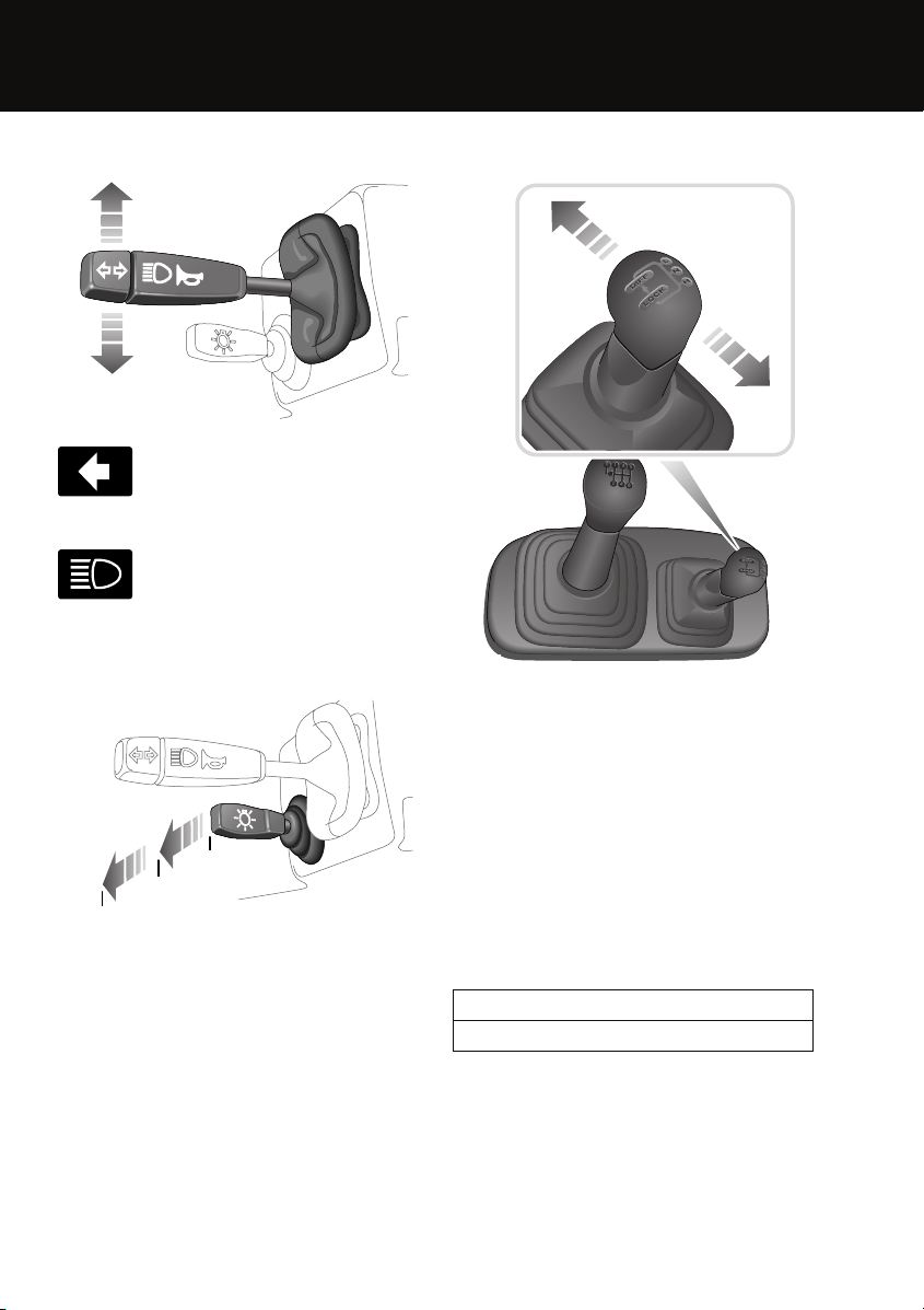
Direction indicators/Headlamp high beam
E85199
Move the lever up or down to
activate the direction indicators; a
warning indicator will flash on the
instrument pack.
Push the lever away from you to
select headlamp high beam. A
warning indicator will illuminate on
the instrument pack.
Exterior lamps master switch
0
1
2
E85195
0 Exterior lamps off
1 Side, tail and instrument panel lamps on
2 Headlamps
The headlamp levelling switch and rear fog
lamp switch are on the centre console.
Transfer gearbox
E85234
Use the transfer gearbox to select High range
H, Low range L or Neutral N.
• Use H for all normal road conditions and
also for off-road dry, level ground.
• Select L only for low-speeds, such as
reversing a trailer or crossing a
boulder-strewn river bed.
• Use N when being towed. When N is
selected, drive cannot be transferred to the
road wheels, even if a gear is selected with
the main gear lever.
Operating note
Do not use L for normal road driving.
20
Page 21
Quick start
Changing range
It is recommended that you change the gear
range while the vehicle is moving.
If you prefer, you can change the gear range
when the vehicle is stationary. See TRANSFER
GEARBOX (page 81).
Changing from L to H
1. Apply slight backward pressure to the
transfer gearbox lever in preparation for
changing.
2. Then, in three simultaneous moves,
depress the clutch pedal, release the
accelerator pedal and pull the transfer
gearbox lever into N.
3. Release the clutch pedal for three seconds,
then depress the clutch pedal and move
the lever firmly into H.
4. Select a suitable main gear and release the
clutch pedal to continue driving.
Changing from H to L
1. With the vehicle slowing down and at less
than 8 km/h (5 mph), depress the clutch
pedal and move the transfer gearbox lever
into N.
2. Just before the vehicle stops, and with the
clutch pedal still depressed, push the lever
into the L position.
3. Select a suitable main gear and release the
clutch pedal to continue driving.
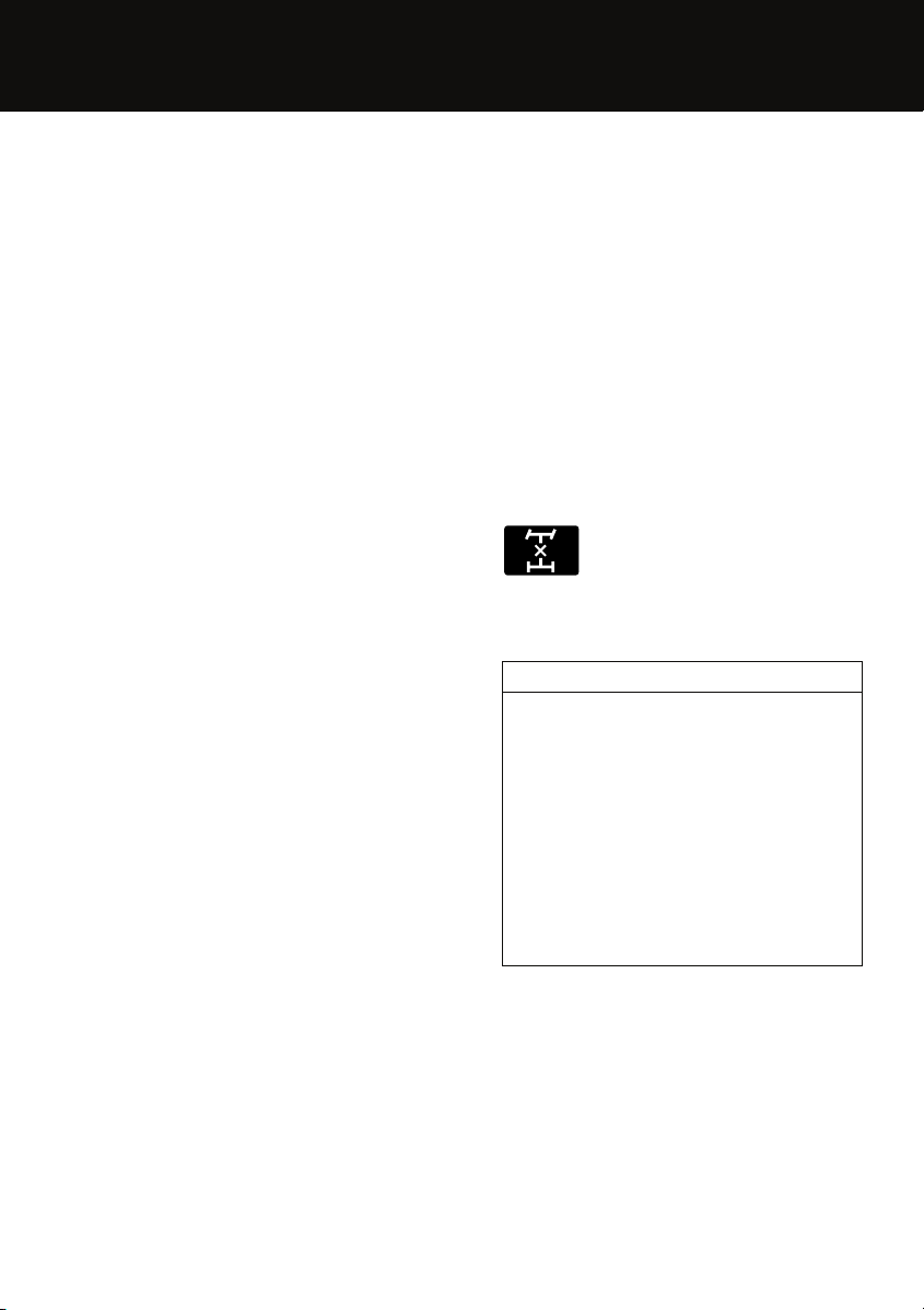
Differential lock
Your vehicle has permanent four-wheel-drive;
however, additional grip may be obtained on
loose and slippery surfaces by locking the
differential.
If you lock the differential when driving, it is
essential that you are travelling in a straight line
on firm ground, and without wheel slip.
• To lock the differential: briefly ease the
accelerator pedal and (only from the H or L
position) move the transfer gearbox lever
to the left, to the Diff Lock position.
• To unlock the differential: move the
transfer gearbox lever to the right, to the H
or L position.
In the instrument panel, the amber
warning indicator illuminates when
the differential lock is actually
engaged, rather than when selected. This
causes a slight delay which is quite normal.
Operating note
Do not engage the differential lock if a wheel
is slipping. This could damage the
transmission.
Do not engage the differential lock from the
transfer gearbox neutral position.
Do not drive above 60 km/h (40 mph) with the
differential locked.
Always unlock the differential for normal road
driving or as soon as you reach a hard grippy
surface.
21
Page 22
Quick start
Battery and tool kit
Battery
The battery is located under the left-hand front
seat. See BATTERY CARE (page 115).
Tool kit
You will have either a bottle jack or a pillar jack.
It is important to read the operating
instructions for the type of jack fitted to your
vehicle. See CHANGING A ROAD WHEEL
(page 128).
Depending on which model you have, the bottle
jack will be stored under the left-hand front
seat with the wheel chock and the wheel brace
or behind the front seats. The pillar jack will be
stored under the second-row seats.
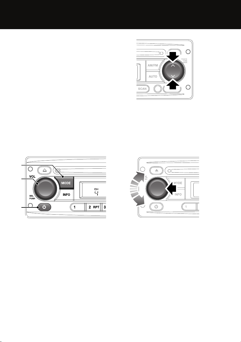
Audio system controls
3
2
E84859
Press and release the up or down buttons to
skip the CD tracks or to search for a radio
station.
Press and hold the up or down buttons to
manually search for a radio station.
Sound settings
1
E86537
Press the button 1 to switch on or off.
Rotate the control 2 to adjust volume.
Repeatedly press the mode button 3 to select
TUNER,CD or AUX.
E85374
You can change a number of settings using the
volume control. These settings can be found in
menu 1 or menu 2.
Menu 1
Press and release the volume control
(arrowed) to access menu 1. Press and release
the volume control repeatedly to scroll through
the menu 1 options.
When the desired setting is displayed, rotate
the volume control to adjust.
22
Page 23
Quick start
Menu 2
Press and hold the volume control (arrowed) to
access menu 2. Press and release the volume
control repeatedly to scroll through the menu 2
options.
When the desired setting is displayed, rotate
the volume control to adjust.
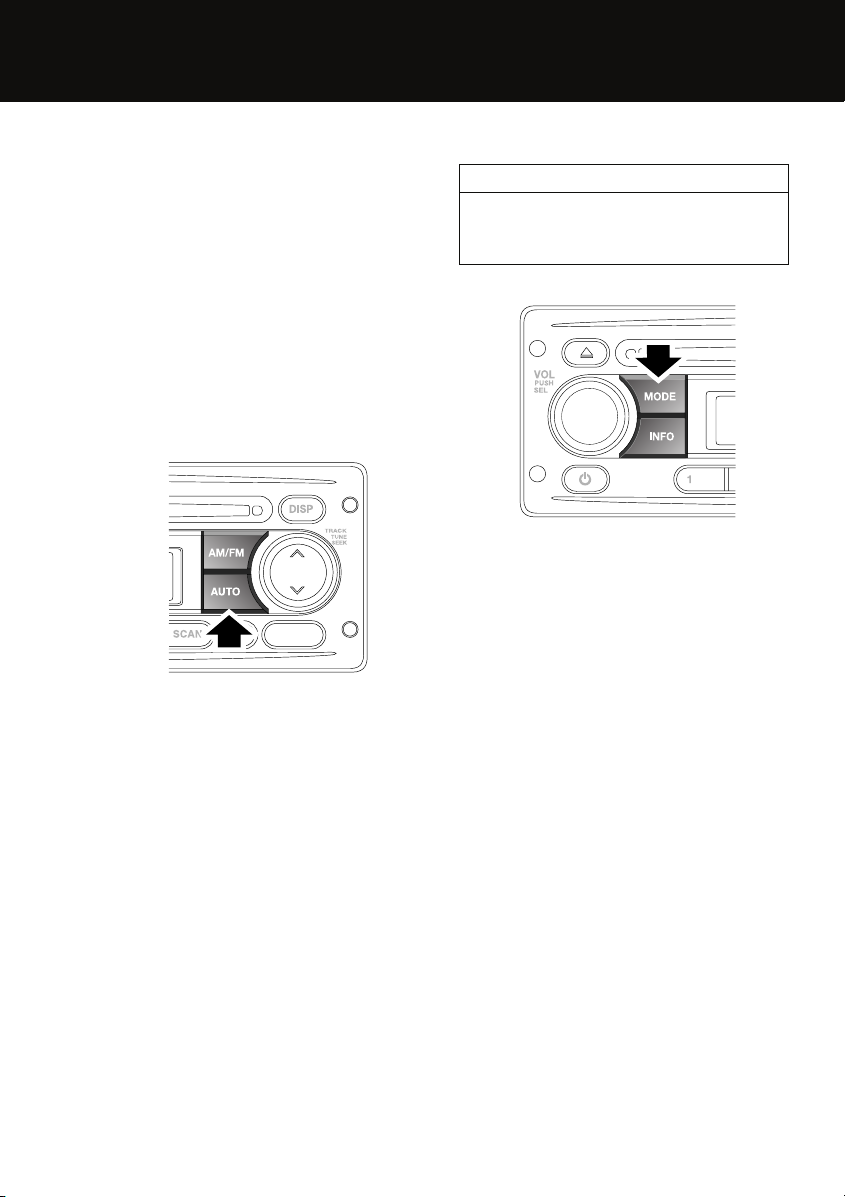
Radio operation
Press the AM/FM button to select the required
waveband. Repeated presses of the button will
scroll through the FM and AM waveband
options.
Storing radio stations
E84816
To automatically store radio stations, select the
required waveband, then press the AUTO
button. Search will be shown on the
information display and the six strongest
stations will be stored under the preset
numbers, in the order in which they are found.
To recall a preset station, press and release one
of the numbered preset buttons.
A selection of radio presets can be stored
manually. See STATION PRESET BUTTONS
(page 160).
CD operation
Compatible disc types
The use of discs with paper labels or double
sided dual format discs (CD/DVD) should be
avoided as they could become jammed.
E85379
Insert a disc, label side up, into the player. The
disc will load and start to play.
To end CD playback, briefly press the pause II
button or the MODE button.
To eject the disc, press the eject button. A
confirmation message will appear on the
display.
23
Page 24
Filling station information
Filling station information
FILLING STATION INFORMATION
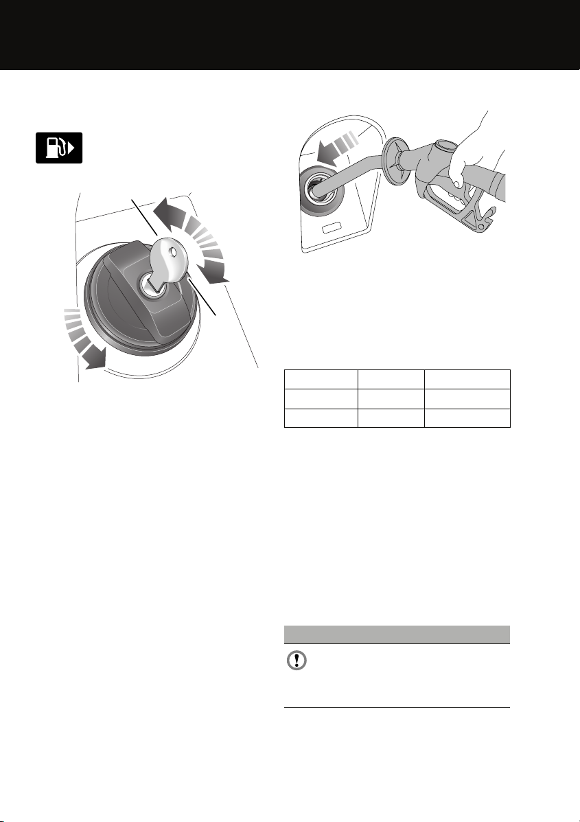
Fuel filler cap
E83705
E94107
To unlock and remove the filler cap:
1. Hold the filler cap steady, insert the key
2. Remove the key.
3. Unscrew the filler cap, gradually at first,
4. Remove the filler cap.
To replace and lock the filler cap:
1. Replace the filler cap into the fuel filler.
2. Turn and tighten the filler cap clockwise,
3. Hold the filler cap steady, insert the key
4. Remove the key.
5. The filler cap is now locked, but can rotate.
A small arrow on the fuel gauge
indicates which side of the vehicle
the fuel filler cap is located.
and turn it a half-turn anti-clockwise.
allowing the fuel tank to vent.
until it clicks three times.
and turn it a half-turn clockwise.
Refuelling
E85240
Never continue filling once the filling station
pump has automatically cut-off.
After refuelling, tighten the filler cap until it
clicks three times.
Fuel tank capacity
Model Litres Gallons
90 57 12.54
110 73 16.06
Tyre pressures
Details of the tyre pressures for each derivative
and wheel and tyre combination can be found
later in this book. See TECHNICAL
SPECIFICATIONS (page 136).
Fuel specification
The correct fuel specification for your vehicle is
shown next to the fuel filler cap. See
TECHNICAL SPECIFICATIONS (page 114).
Incorrect fuelling
CAUTION
If the fuel tank is accidentally filled with
the wrong type of fuel, it is essential that
the engine is not started and that you seek
qualified assistance.
24
Page 25

Filling station information
Engine oil specification
Model Specification
Diesel engine Use only 5W-30 oil
meeting Land Rover
specification
WSS-M2C913-B.
Engine coolant specification
Top-up to the upper level indicator mark. Use
only a 50% mix of water and Texaco XLC
antifreeze. See ENGINE COOLANT CHECK
(page 108).
25
Page 26
Introduction
Introduction
SYMBOLS GLOSSARY
Warnings
WARNING
Safety warnings are included in this
handbook. These indicate either a
procedure which must be followed precisely,
or information that should be considered with
great care in order to avoid the possibility of
personal injury.
Cautions
CAUTION
Cautions are included in this handbook.
These indicate either a procedure which
must be followed precisely, or information that
should be considered with great care in order
to avoid the possibility of damage to your
vehicle.
Symbols
This recycling symbol identifies
those items that must be disposed
of safely in order to prevent
unnecessary damage to the environment.
This symbol identifies those
features that can be adjusted,
disabled or enabled by a Land Rover
Dealer/Authorised Repairer.
LABEL LOCATIONS
Warning labels attached to your
vehicle bearing this symbol mean:
E83651
Do not touch or adjust components
until you have read the relevant
instructions in the handbook.
Labels showing this symbol
indicate that the ignition system
E83652
utilises very high voltages. Do not
touch any ignition components
while the starter switch is turned on.
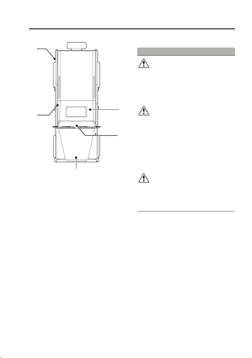
Warning labels
Labels are attached to your vehicle at several
positions. These are applied to draw your
attention to important subjects, e.g. tyre
pressures, tow bar use, roll-over risk, engine
compartment hazards, etc.
26
Page 27
Introduction
5
4
E85734
1. Fan cowl - Fan warning label, air
conditioning label and Genuine Parts
label
2. Top face of battery - Battery warning
symbols
3. Facia - Transmission label
4. On right-hand rear wheel arch - Vehicle
jacking label. Australia only - Tyre
pressures label
5. Adjacent to the fuel filler cap - Fuel
specification label
It is important that you are familiar with these
subjects to ensure that your vehicle and its
features are used safely. Using the index at the
back of this handbook, refer to the relevant
topic for more information.
1
2
3
HEALTH AND SAFETY
WARNINGS
Your vehicle has a higher ground
clearance and hence, a higher centre of
gravity than ordinary passenger cars, to
enable the vehicle to perform in a wide variety
of off-road applications. An advantage of the
higher ground clearance is a better view of the
road allowing you to anticipate problems.
The vehicle is not designed for
cornering at the same speed as
conventional passenger cars any more than a
low-slung sports car is designed to perform
satisfactorily under off-road conditions. If at
all possible, avoid sharp turns or abrupt
manoeuvres. As with other vehicles of this
type, failure to operate the vehicle correctly
may result in loss of control or vehicle
roll-over.
The vehicle should not be parked over
long dry grass or other combustible
material, particularly during dry weather. As
the heat generated by the exhaust and
emission control systems may be sufficient to
start a fire.
DATA RECORDING
Service data recording
Service data recorders in your vehicle are
capable of collecting and storing diagnostic
information about your vehicle. This potentially
includes information about the performance or
status of various systems and modules in the
vehicle such as engine, throttle, steering or
brakes.
In order to properly diagnose and service your
vehicle, Land Rover and service and repair
facilities may access vehicle diagnostic
information through a direct connection to
your vehicle.
27
Page 28
Introduction
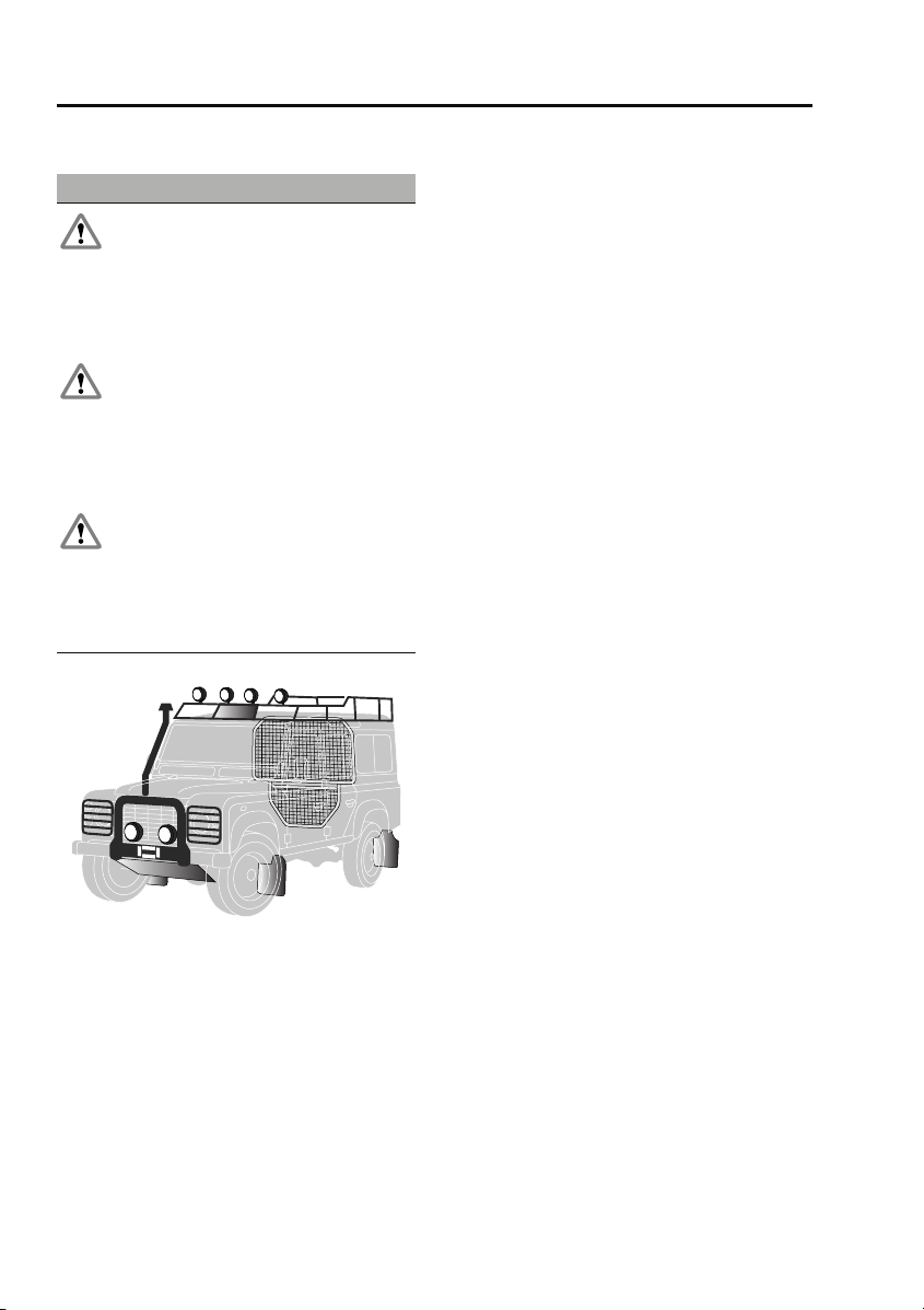
PARTS AND ACCESSORIES
WARNINGS
The fitting of non-approved parts and
accessories, or the carrying out of
non-approved alterations or conversions, may
be dangerous and could affect the safety of the
vehicle and occupants and also invalidate the
terms and conditions of the vehicle warranty.
Land Rover will not accept any liability
for death, personal injury or damage to
property which may occur as a direct result of
fitment of non-approved accessories or the
carrying out of non-approved conversions to
Land Rover vehicles.
Land Rover strongly advise against
making any modifications to the
suspension or steering system. This could
seriously affect the handling and stability of
the vehicle leading to loss of control or
roll-over.
parts and accessories that have been
developed and tested to the same stringent
standards as the original components will
safeguard the continued reliability, safety and
performance of your vehicle.
To augment the vehicle's already impressive
performance, a comprehensive range of Land
Rover approved spare parts and accessories is
available, enabling the vehicle to fulfil a wide
variety of roles, and enhancing and protecting
the vehicle in the many tasks to which it can be
applied.
Land Rover parts are the only parts built to
original equipment specifications and
approved by Land Rover designers; this means
that every single part and accessory has been
rigorously tested by the same engineering
team that designed and built the vehicle and
can therefore be guaranteed for twelve months
with unlimited mileage.
A full list and description of all accessories is
available from your Land Rover
Dealer/Authorised Repairer.
E88154
The vehicle has been designed, built and tested
to cope with a variety of off-road driving
conditions, some of which can place the
severest possible demands on control systems
and components. As such, fitting replacement
28
Page 29
Introduction
Electrical equipment
WARNING
It is extremely hazardous to fit or
replace parts or accessories, the
installation of which requires the dismantling
of, or addition to, either the electrical or fuel
systems.
Always consult a Land Rover
Dealer/Authorised Repairer before fitting any
accessory.
Fitting inferior quality parts or accessories,
may be dangerous and could invalidate the
vehicle warranty.
It is recommended that you always consult a
Land Rover Dealer/Authorised Repairer for
advice regarding the approval, suitability,
installation and use of any parts or accessories
before fitting.
After-sales service
Travelling abroad
In certain countries, it is a legal requirement to
fit parts made to the vehicle manufacturers'
specification.
Owners should ensure that any parts or
accessories fitted to the vehicle while travelling
abroad, will also conform to the legal
requirements of their own country when they
return home.
E84193
The After Sales Parts service is of paramount
importance, both in the UK and across the
world. In the UK there are over 100 authorised
Land Rover Dealers/Authorised Repairers, all
computer linked for rapid ordering of parts and
accessories.
In addition, with franchised representation in
over 100 countries worldwide, Land Rover are
able to support your vehicle wherever you go.
29
Page 30
Keys and remote controls
Keys and remote controls
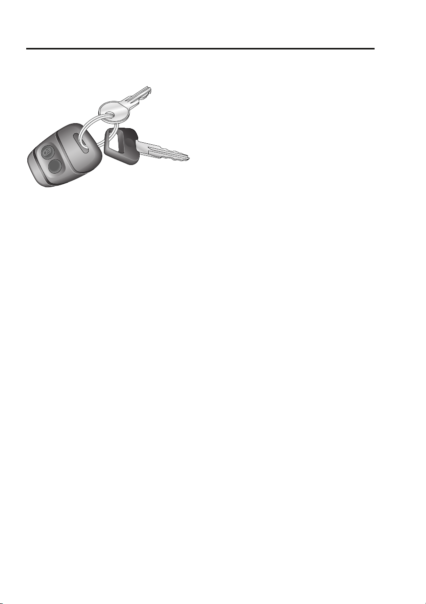
USING THE KEY
E85174
You have been supplied with two sets of keys
comprising:
• A black key for operating the starter switch
and the door locks.
• A smaller, metal key, to operate the fuel
filler cap lock. See REFUELLING
(page 90).
Insert the black key into the driver's door lock
and turn it towards the rear of the vehicle to
lock and towards the front of the vehicle to
unlock.
If the doors are locked with the key, the engine
will be immobilised, but the alarm system is
not armed.
Only unlock the doors using the key, if they
were locked using the key. Unlocking the doors
with the key may not disarm the alarm. The
alarm must be disarmed using the remote
control.
Note: On vehicles not fitted with central
locking, the key must be used to lock and
unlock each door individually.
GENERAL INFORMATION ON RADIO
FREQUENCIES
Note: The radio frequency used by your remote
control may be used by other devices. For
example: amateur radios, medical equipment,
wireless headphones, or other remote control
devices. This may cause the frequency to be
jammed, and prevent your remote control from
operating correctly.
Environmental conditions can affect the
operation of remote controls and the operating
range may vary considerably depending on the
vehicle's location.
30
Page 31

Keys and remote controls
USING THE REMOTE CONTROL
Remote control
WARNING
Never leave the remote control in the
vehicle if children or animals are also
left in the vehicle. The vehicle's systems and
remote control functions could be operated,
which may result in injury.
Note: The operational range of the remote
control will vary considerably depending on
atmospheric conditions and interference from
other transmitting devices.
The vehicle is supplied with two remote
controls.
1
E85175
1. Unlock.
2. Lock.
2
Unlocking
Press the unlock (plain) button briefly to
unlock the doors (including the taildoor) and
deactivate the alarm. The hazard warning
lamps will flash once to indicate that the vehicle
is unlocked and the alarm has been
deactivated. The interior lamps will illuminate
to assist entry to the vehicle.
Note: On vehicles not fitted with central
locking, the remote control will not unlock the
doors - the key must be used.
Locking
Press briefly to lock the doors
(including the taildoor) and activate
the alarm. The hazard warning
lamps will flash three times and the alarm
indicator in the instrument panel starts to flash,
to indicate that the vehicle is secure.
Note: On vehicles not fitted with central
locking, the remote control will not lock the
doors - the key must be used.
Remote battery
WARNING
The remote control contains delicate
electronic circuits and must be
protected from impact and water damage,
high temperatures and humidity, direct
sunlight and the effects of solvents, waxes and
abrasive cleaners.
When the battery needs replacing, it will be
apparent from the following symptoms:
• The remote control will only work every
other operation when unlocking.
• The hazard warning lamps will not flash
when the alarm is disarmed.
Do not remove the battery until you are ready
to install the replacement.
31
Page 32

Keys and remote controls
The engine will immobilise, five minutes after
the key is removed from the starter switch (or
30 seconds after the starter switch has been
turned off and the driver's door opened). If
battery replacement is not completed within
this period, the emergency key access code will
need to be entered before the remote control
can be synchronised.
Always fit a Land Rover STC 4080 or a
Panasonic CR2032 replacement battery
(available from a Land Rover
Dealer/Authorised Repairer).
Battery replacement
4. Slide the battery out of its clip, taking care
to avoid touching the circuit board or the
contact surfaces of the clip.
5. Press and hold one of the buttons for at
least five seconds (this will drain any
residual power from the remote control).
6. Fit the new battery, ensuring that correct
polarity is maintained (+ side facing up).
Finger marks will adversely affect battery
life; if possible, avoid touching the flat
surface of the battery and wipe them clean
before fitting.
7. Press the two halves of the remote control
firmly together and ensure that both halves
are fully joined, to prevent moisture from
entering the remote control.
8. Operate the lock (padlock symbol) button
at least four times within range of the
vehicle, to resynchronise the remote
control.
9. Press the unlock button once to unlock
The remote control is now ready for use.
E85176
1. Unlock the vehicle and disarm the alarm.
2. Turn the starter switch to position II, then
turn to position 0 and remove the key.
3. Carefully prise the remote control apart.
Start from the key ring end, using a coin or
small screwdriver. Avoid damaging the
seal between the two halves of the case
and do not allow dirt or moisture to get
inside the remote control.
32
Page 33

Locks
Locks
LOCKING AND UNLOCKING
Locking and unlocking from inside the
vehicle
WARNING
Do not depress the sill buttons as a
means of locking the vehicle from
outside the vehicle. This process - known as
slam-locking - is not recommended, because
keys can be locked inside accidentally.
Note: On vehicles fitted with central door
locking, slam locking of the driver's door is
prohibited.
E85177
From inside the vehicle, each door can be
individually locked/unlocked by
depressing/lifting the appropriate sill locking
button.
On vehicles with central door locking,
operation of the driver's door sill locking
button, locks all the other doors too. However,
engine immobilisation and interior space
protection are suspended unless the remote
control lock button is pressed as well.
Note: Information on operating the child safety
locks is given later in this handbook. See
CHILD SAFETY LOCKS (page 50).
Taildoor
From outside, use the key to lock and unlock
the taildoor: Turn the key clockwise to lock and
counterclockwise to unlock.
E85178
From inside the vehicle, ensure the door is
closed, then push the locking catch up to lock
or down to unlock the taildoor.
33
Page 34

Locks
Tailgate
CAUTION
The tailgate is not a load-bearing surface.
E86818
Mislock
If one of the doors, the bonnet or the taildoor
are not shut fully when the remote control lock
button is pressed, the hazard lamps will fail to
flash, indicating a mislock. If this occurs, the
alarm system will not be fully armed. On
vehicles fitted with central door locking, the
doors will not lock in the event of a mislock.
Shut the open aperture. The hazard lamps will
flash and the alarm system will be fully armed.
Note: If a mislock occurs as a result of an open
door, interior space protection will not be
activated.
Note: If a mislock occurs as a result of an open
bonnet, the door apertures will still be
protected by the alarm system and interior
space protection will be active.
To latch the tailgate:
• Lift the tailgate and locate over both the
latch plates as shown.
• Pivot the latch plates upwards and
forwards through 90 degrees.
• Slide the latch plates down to secure.
Reverse the process to open the tailgate.
34
Page 35

Alarm
Alarm
ARMING THE ALARM
The alarm system is automatically
armed, and the engine immobilised,
when the remote lock button is
pressed. The hazard lamps will flash to indicate
that the alarm is armed.
Once armed, the alarm will sound if:-
• a door, the bonnet or the taildoor are
opened.
• movement is detected within the vehicle
interior.
• the vehicle battery is disconnected.
• an attempt is made to disconnect the alarm
siren.
Note: If the alarm is armed and a window or the
sunroof are left open the alarm will sound due
to movement of air currents.
Alarm indicator
E85180
The alarm status is displayed by the indicator in
the speedometer.
• Indicator off - alarm disarmed.
• Indicator flashes rapidly for 10 seconds
when the remote lock button is pressed,
then adjusts to a slower frequency - the
alarm has been armed.
• If the indicator fails to adjust to a slower
frequency after the initial 10 second
period, the remote control battery needs
replacing.
• Indicator flashes rapidly when the alarm is
disarmed - the alarm has been triggered.
• Indicator flashes slowly - the engine is
immobilised, but the alarm is disarmed.
• Indicator illuminates (without flashing) for
10 seconds before adjusting to a slow
frequency flash - the driver's door is not
closed.
Engine immobilisation
Engine immobilisation prevents the engine
from being started without a valid key and
remote control and is activated whenever the
alarm is armed using the remote control. In
addition, the immobiliser activates
automatically under the following conditions:
• Thirty seconds after the starter switch has
been turned off and the driver's door is
opened.
• Five minutes after the starter switch is
turned off or after the alarm system is
disarmed (if the starter switch has not
been turned on).
Note: Details on how to deactivate engine
immobilisation are given later in this section.
See DISARMING THE ALARM (page 36).
35
Page 36

Alarm
DISARMING THE ALARM
When the vehicle is unlocked using
the remote control, the alarm is
automatically disabled and the
engine is remobilised. The hazard lamps will
flash once to indicate that the alarm is disabled.
Note: If the remote control is lost, damaged or
fails to operate, it is necessary to enter the
emergency key access code, to disarm the
alarm and deactivate engine immobilisation.
Deactivating engine immobilisation
Engine immobilisation is deactivated
automatically whenever the vehicle is unlocked
using the remote control. Engine
immobilisation is also deactivated when the
starter switch is turned to position II, provided
the remote control is on the same key ring as
the key and in close proximity to the switch.
If, however, the remote control is damaged, or
fails to operate, immobilisation can only be
deactivated by entering the emergency key
access code.
Emergency key access
Note: If the remote control cannot be used, it is
impossible to disarm the alarm in the normal
way. The alarm will sound (for 30 second
durations) as soon as a door is opened and will
continue until the code has been entered.
To deactivate engine immobilisation manually,
in the event of remote control failure, follow the
procedure below to enter the unique four digit
emergency key access code. The code for your
vehicle is recorded on the Security card.
E85179
1. Remove the remote control from the key
ring and keep it well away from the starter
switch while entering the code.
2. Unlock the driver's door using the key,
open the door and enter the vehicle. Shut
the driver's door.
3. Insert the key in the starter switch, turn
and hold the key in position II until the
alarm sounds. Then, turn off the starter
switch and open and close the driver's
door.
4. Turn the starter switch to position II the
required number of times to enter the first
digit of the code (if the digit is 4, turn the
key to position II and then back to position
0 four times).
5. Open and close the driver's door (this will
enter the first digit of the code).
6. Turn the starter switch to position II and
back to 0 the required number of times to
enter the second digit of the code, then
open and close the driver's door.
7. Turn the starter switch to position II and
back to 0 the required number of times to
enter the third digit of the code, then open
and close the driver's door.
36
Page 37

Alarm
8. Turn the starter switch to position II and
back to 0 the required number of times to
enter the fourth digit of the code, then
finally, open and close the driver's door
one more time.
If the code has been entered correctly, the
alarm indicator will extinguish, the alarm will
stop sounding and the engine can be started.
If an incorrect code has been entered:
If the code is entered incorrectly, the alarm
sounder will sound twice, the alarm indicator
will continue to illuminate and the engine will
fail to start. Before entering the code again,
turn the starter switch to position II and hold in
this position for five seconds.
After three failed entry attempts, the security
system invokes a delay period of 30 minutes,
during which the system will not accept further
attempts to enter a code.
Memorise the emergency key access code or
keep the Security card on your person, in case
of emergencies. Never leave the card in the
vehicle.
Deactivating the alarm when triggered
If the alarm has been triggered it can be
deactivated by pressing either of the remote
control buttons.
37
Page 38

Seats
Seats
SITTING IN THE CORRECT POSITION
1
E88155
WARNING
Do not adjust the seat while the vehicle
is moving. Doing so could cause loss of
vehicle control and personal injury.
The seat, head restraint and seat belt, all
contribute to the protection of the user. Correct
use of these components will give you greater
protection, therefore you should always sit in
an upright position, with the base of your spine
as far back as possible and seatback reclined
no more than 30 degrees (1).
• Adjust the head restraint so that it's
highest point is level with the top of your
head.
• Position the seat belt so that it is mid-way
between your neck and your shoulder. Fit
the strap tightly across your hips, not
across your stomach.
• Ensure that your driving position is
comfortable, and enables you to maintain
full control of the vehicle.
38
Page 39

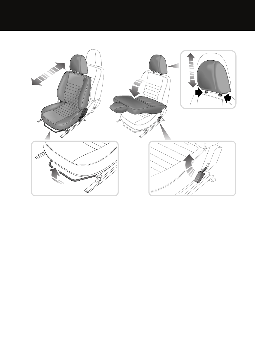
MANUAL SEATS
1
1
Seats
3
2
2
E85185
1. Fore and aft adjustment.
2. Seat back angle adjustment.
3. Head restraint height adjustment. See
HEAD RESTRAINTS (page 41).
Front seat base removal
CAUTION
On vehicles equipped with seat heaters,
an electrical lead connects the heater unit
in the seat cushion with the vehicle wiring
harness. When removing the seat base, care
must be taken to avoid straining or damaging
the lead. If necessary, carefully disconnect the
lead from the seat base.
39
Page 40

Seats
It is necessary to remove the front seat base to
access the following:
• Driver's seat
• Battery compartment
• Wheel change tool kit
• Passenger seat
• Secondary fuse box
1
2
3
Refitting the seat base
WARNING
Ensure that the seat base is securely in
place before driving.
2
1
3
4
4
E85186
Remove the relevant seat base as follows:
1. Firmly pull up the front of the seat base, to
release from the retaining clips.
2. Pull the seat base towards the front of the
vehicle to remove.
3. Release the catch on the front of the
underseat compartment (solid arrow in
illustration).
4. Slide the lid forwards to remove.
E85187
Refit the seat base as follows:
1. Slide the underseat compartment lid back
into position.
2. Secure the catch and (if necessary)
reconnect the seat heater electrical lead.
3. Insert the rear of the seat base, to engage
the two locating pins.
4. Push down firmly on the front of the seat
base, to re-engage the retaining clips.
40
Page 41

Seats
HEAD RESTRAINTS
E94110
WARNINGS
Head restraints are designed to support
the head, not the back of the neck. The
restraint must be positioned correctly to
restrain rearward movement of the head in a
collision. An incorrectly adjusted head
restraint increases the risk of death or serious
injury in the event of a collision.
Adjust the head restraint so that the top
of the head restraint is above the centre
line of the head. An incorrectly adjusted head
restraint increases the risk of death or serious
injury in the event of a collision. See SITTING
IN THE CORRECT POSITION (page 38).
Do not drive, or carry passengers with
the head restraints removed from
occupied seats. The absence of a correctly
adjusted head restraint increases the risk of
death or serious injury in the event of a
collision.
WARNINGS
Never adjust the head restraints while
the vehicle is in motion. An incorrectly
adjusted head restraint increases the risk of
death or serious injury in the event of a
collision.
Raising
To raise a head restraint, pull up on the
restraint until it is in the required position.
Lowering
To lower a head restraint, press the release
button (arrowed) before lowering the head
restraint to the required position.
REAR SEATS
WARNINGS
Always ensure that objects carried
within the vehicle are secured properly.
Unsecured items can cause death or serious
injury in the event of an impact or sudden
manoeuvre.
Never allow passengers to travel in the
load space under any circumstances.
All vehicle occupants should be seated
correctly, and wear a seat belt at all times
when the vehicle is in motion. Failure to do so
will greatly increase the risk of death and
serious injury in the event of an accident or
heavy braking.
The third row seats can be folded individually
as required to increase loadspace. The split
fold second-row rear seat can be folded
completely to accommodate large loads, or
partially to accommodate long loads and still
retain seating for passengers.
41
Page 42

Seats
Folding the rear seats
WARNING
Ensure that if the rear head rests are
removed they are stored securely.
Never leave them loose in the vehicle, as they
can cause serious injury or death in the event
of an accident, heavy braking, or sudden
manoeuvres.
1
CAUTION
To prevent marking the seats, ensure
that the seat belt buckles are in the
stowed position before folding the seats.
Second-row seats
CAUTION
Before folding the second-row seats, it
may be necessary to adjust the front
seats forwards and adjust the front seat
backrests to a more upright position. This
prevents damage caused by the folded
second-row seats rubbing against the front
seats.
1. Fully lower the head restraints.
2. Push the catch down to release the seat
back, then fold the seat back forwards.
3. Pull the strap towards the front of the
vehicle to pivot the seat into the stowed
position.
4. If required, repeat the process for the rest
of the second-row seat.
5. If folding the double seat or the whole
second-row, fold the floor-mounted latch
striker bar(s) into the floor, to create a flat
loading area.
E88187
2
2
3
3
5
42
Page 43

Seats
Third-row seats
2
Raising the rear seats
WARNING
Ensure that when a rear seat is raised,
the locking mechanism is fully
1
engaged. Failure to do so can increase the risk
of death or serious injury in the event of an
accident or sudden manoeuvre or heavy
braking.
2
3
3
E85190
1. Lower the head restraints.
2. Push the seat back locking catch
downwards to release and fold the seat
back forwards.
3. Pull the seat base locking lever upwards to
unlock, then fold the seat upwards towards
the side of the vehicle until the retaining
catch engages.
43
Page 44

Seats
Second-row seats
3
Note: If the front seats have been adjusted
while the second-row seats were folded, it may
21
2
be necessary to adjust the front seats forward
to allow the second-row seats to be raised.
Also check that the second-row seat head
restraints are in the lowered position.
1. Raise the floor-mounted latch striker
bar(s) forwards from the floor, as far as
they will go.
2. Pull the strap towards the rear of the
vehicle to pivot the seat out of the stowed
position.
3. Unfold the seat back rearwards, ensuring
that the catch engages.
Note: If the floor-mounted latch striker bar is
not raised into the correct position, it will not
be possible to fully unfold the seat back.
3
E88188
Note: If the vehicle is parked on a slope, it is
possible that the floor-mounted latch striker
bar(s) will not align correctly with the locking
mechanism and will fail to engage correctly.
For this reason, it is recommended that the
seats are raised while the vehicle is on level
ground.
44
Page 45

Seats
Third-row seats
HEATED SEATS
1
E85193
1
To prevent the battery from becoming
discharged, the seat heaters should only
3
2
be operated when the engine is running.
With the starter switch turned to position II,
press the appropriate switch to activate the
seat heater (the switch indicator will
illuminate). The seat heaters will operate
intermittently to maintain the seat temperature
within a factory set temperature range.
Press the switch again to turn off.
Note: Rear seats are not equipped with seat
heaters.
CAUTION
E85192
1. Pull the release catch inwards to unlatch
the seat assembly, then lower the seat
base into position until securely latched.
2. Unfold the seat back rearwards, ensuring
that the catch engages.
3. Adjust the head restraint to the correct
position.
45
Page 46

Seat belts
Seat belts
PRINCIPLE OF OPERATION
Seat belts
E82942
WARNINGS
Seat belts are designed to bear upon
the bony structure of the body, and
should be worn low across the front of the
pelvis or the pelvis, chest and shoulders, as
applicable; wearing the lap section of the belt
across the abdominal area must be avoided.
Seat belts should be adjusted as firmly
as possible, consistent with comfort, to
provide the protection for which they have
been designed. A slack belt will greatly reduce
the protection afforded to the wearer.
Care should be taken to avoid
contamination of the webbing with
polishes, oils and chemicals, and particularly
battery acid. Cleaning may safely be carried
out using mild soap and water.
The belt should be replaced if webbing
becomes frayed, contaminated or
damaged.
It is essential to replace the entire
assembly after it has been worn in a
severe impact even if damage to the assembly
is not obvious.
Belts should not be worn with the
straps twisted.
WARNINGS
Do not carry hard, fragile, or sharp
items between your person and the seat
belt. In an impact the pressure from the seat
belt on such items can cause them to break,
which in turn may cause death or serious
injuries.
Each belt assembly must only be used
by one occupant; it is dangerous to put
a belt around a child being carried on the
occupant's lap.
The occupants of the front seats should
not travel with the seat back at more
than 30 degrees from upright. Doing so will
reduce the protection afforded by the seat belt.
Seat belt safety
WARNINGS
Seat belts should be worn by all vehicle
occupants, for every journey no matter
how short. failure to do so will greatly increase
the risk of death or serious injury in the event
of an accident.
Never wear just the lap belt or just the
shoulder belt of a lap/shoulder diagonal
seat belt. Both of these actions are extremely
dangerous and may increase your risk of
injury.
No modifications or additions should
be made which prevent the seat belt
mechanism from taking up slack, or prevent
the seat belt being adjusted to remove slack. A
slack seat belt offers a greatly reduced level of
occupant protection in an impact.
If any damage, wear, cuts, defects, or
impaired operation are noted with the
seat belts, the vehicle should be taken to a
Land Rover Dealer/Authorised repairer for
immediate attention. Do not use the vehicle if
the seat belts cannot be operated correctly.
46
Page 47

Seat belts
WARNINGS
When using seat belts to restrain items
other than occupants, take care to
ensure that the belts are not damaged, or
exposed to sharp edges.
Care must be taken to avoid
contaminating the seat belt webbing,
and seat belt mechanisms with any chemicals,
liquids, grit, dirt, or cleaning products. If the
seat belts do become contaminated they
should be replaced immediately.
Contaminated seat belts my not operate
correctly in an impact and cannot be relied
upon.
Seat belt checks
Note: If the vehicle is parked on an incline, the
seat belt mechanism may lock. This is not a
fault, and the belt should be gently eased out
from the upper anchorage.
The seat belts should be inspected regularly to
check for fraying, cuts, or wear to the webbing,
and the condition and security of the
mechanism, buckles, adjusters, and mounting
points.
Checks
• With the seat belt fastened, give the
webbing near the buckle a quick upward
pull. The buckle must remain securely
locked.
• With the seat belt unfastened, unreel the
seat belt to the limit of its travel. Check that
it unreels smoothly with no snatches or
snags. Allow the belt to fully retract, again
checking for smooth operation.
• Partially unreel the seat belt, then hold the
tongue plate and give a quick forward pull.
The mechanism must lock and prevent any
further unreeling.
If any of the seat belts fail to meet those
criteria, immediately contact you Land Rover
Dealer/Authorised Repairer.
FASTENING THE SEAT BELTS
1
2
E85194
1. Draw the belt out smoothly, ensure that the
seat position, and your position on the seat
are correct. The belt should lay flat across
the pelvis, chest, and mid-point of the
collar bone between the neck and
shoulder.
2. With the seat belt correctly positioned,
place the metal tongue into the buckle
nearest to you. Press it in until a click is
heard.
Releasing the seat belts
Note: When releasing the seat belt it is
advisable to hold the belt before pressing the
release button. This will prevent the belt from
retracting too quickly.
To release the seat belt, press the red button.
47
Page 48

Seat belts
USING SEAT BELTS DURING
PREGNANCY
E82643
WARNINGS
Position the seat belt correctly for the
safety of the mother and unborn child.
Never wear just the lap strap, and never sit on
the lap strap whilst using just the shoulder
strap. Both of these actions are extremely
dangerous, and may increase your risk of
serious injury in the event of an accident or
during emergency braking.
Never place anything between you and
the seat belt in an attempt to cushion
the impact in the event of an accident. It can be
dangerous, and will reduce the effectiveness
of the seat belt in preventing injury.
Position the lap strap comfortably across the
hips beneath the abdomen. Place the diagonal
part of the seat belt between the breasts and to
the side of the abdomen. Ensure that the seat
belt is not slack or twisted.
48
Page 49

Child safety
Child safety
CHILD SEATS
WARNINGS
Crash statistics show that children are
safest when properly restrained on the
rear seat.
Do not use a forward facing child seat
until the child using it is above the
minimum weight of 9 kg (20 lb.) and able to sit
up unaided. Up to the age of two, a child's
spine and neck are not sufficiently developed
to avoid injury in a frontal impact.
Do not allow a baby or infant to be held
or carried on the lap. The force of a
crash can increase effective body weight by as
much as thirty times, making it impossible to
hold onto the child. Children typically require
the use of a booster seat appropriate to their
age and size, thereby enabling the seat belts to
be properly fitted, reducing the risk of injury in
a crash. Children could be endangered in a
crash if their child restraints are not properly
secured in the vehicle.
Do not use a child seat that hooks over
the seat back. This type of seat cannot
be satisfactorily secured and is unlikely to be
safe for your child.
It is very important for all infants and children
under 12 years of age to be restrained in a
suitable child safety seat appropriate to their
age and size.
Child restraint check list
Every time a child travels in the vehicle observe
the following:-
• Use appropriate child restraints.
• Carefully follow the restraint system
manufacturers instructions.
• Adjust the harnesses for every child on
every trip.
• Ensure that all slack is removed from the
adult seatbelt.
• Always check the security of the child
restraint.
• Do not dress a child in bulky clothing, or
place any objects/padding between the
child and the restraint.
• Regularly check the fit and condition of
child restraints. If the fit is poor, or
wear/damage is visible replace the
restraint immediately.
• Set a good example - always wear your
seat belt.
Note: The information contained in the
following table may not be applicable to all
countries. If you are in any doubt regarding the
type and fitment of child seats seek advice from
your Land Rover Dealer/Authorised Repairer.
49
Page 50

Child safety seating and positions
Mass group 0 = Up to 10 kg
(22 lb)
Seating
positions
Front
passenger
Second-row
seats
Third-row
seats
UU UUU
UU UUU
UU UUU
0+ = Up to 13 kg
Child safety
I = 9-18 kg
(29 lb)
(20-40 lb)
II = 15-25 kg
(40-67 lb)
III = 25-36 kg
(67-80 lb)
• U = Suitable for universal category
restraints approved for this mass group.
• UF = Suitable for Forward-facing universal
category restraints approved for this mass
group.
• X = Not suitable for children in this mass
group.
CAUTION
Information given within the table is
correct at the time of going to press.
However, availability of child restraints may
change. Please consult your Land Rover
Dealer/Authorised Repairer for the latest
recommendation.
Note: The legislation which governs how and
where children should be carried when
travelling in a vehicle, is subject to change. It is
the responsibility of the driver to comply with
all regulations in force.
BOOSTER CUSHIONS
In a situation where a child is too large to fit
into a child safety seat, but is still too small to
safely fit the three point belt properly, a booster
seat is recommended for maximum safety.
Follow the manufacturer's instructions for
fitting and use, then adjust the seat belt to suit.
CHILD SAFETY LOCKS
E85681
Child safety locks are fitted to the rear doors to
allow you to prevent accidental opening of the
doors when the vehicle is in motion.
If children are to be carried in the rear seat
positions, it is recommended that the rear door
interior handles are disabled.
Note: For convenience, the rear door interior
handles should be re-enabled when carrying
adult passengers in the rear seat positions.
To change the child lock settings:-
1. Open the door to access the child safety
lock.
2. Move the locking lever up to enable, or
down to disable the interior door handle,
as required.
50
Page 51

Lighting
Lighting
LIGHTING CONTROL
Main lighting switch
0
1
2
E85195
1. Headlamps/side lamps off.
2. Side, tail and instrument panel lamps on.
3. Headlamp dipped beam on.
Main beam
REAR FOG LAMPS
E85197
Rear fog lamps will only operate when dipped
beam headlamps are selected. Press the rear
fog lamp button to switch on, press again to
switch off.
Switching off the headlamps or turning the
starter switch to position 0, will also
automatically extinguish the rear fog lamps
(the fog lamps will then need to be selected
again manually, when needed). Always switch
fog lamps off as soon as visibility permits.
E85196
1. When the headlamp dipped beams are
switched on, push the indicator stalk to
change to full beam.
2. To flash the headlamps at anytime, briefly
pull the indicator stalk and release it.
When the headlamp main beam is
on, the main beam warning
indicator (blue) will illuminate.
Note: Do not use main beam where it may
dazzle other road users.
51
Page 52

Lighting
HEADLAMP LEVELLING
E85733
Use the headlamp levelling control to account
for vehicle loading changes, so that headlamps
provide adequate illumination without dazzling
other road users.
Vehicle load Switch position
Driver only
(loadspace empty)
Driver and front
seat passenger
(loadspace empty)
Driver and passengers
in all seats
(loadspace empty)
All seats occupied
and loadspace
loaded to maximum
rear axle weight
Driver only, with
loadspace loaded
to maximum rear
axle weight
0
0
1
2
3
Vehicles fitted with front seats only
Positions 1 and 2 should only be used when
required, according to the distribution and
weight of the load being carried.
HAZARD WARNING FLASHERS
E85198
Press to operate; all the direction indicator
lamps (including those fitted to a trailer) will
flash together. The direction indicator warning
lamps in the instrument pack will also flash
while the hazard warning flashers are
operating.
Note: Hazard warning flashers can be used
with the starter switch on or off.
52
Page 53

Lighting
DIRECTION INDICATORS
E85199
The direction indicators are operated using the
indicator stalk. Move the stalk up to indicate a
right turn and down to indicate a left.
Hold the stalk part-way up or down against
spring pressure to indicate a lane change.
INTERIOR LAMPS
OFF
ON
E85200
• OFF - lamp permanently off.
• Central - lamp illuminates automatically.
• ON - Lamp continuously on.
With the switch in the centre position, the
interior lamp illuminates automatically
whenever a door is opened or the alarm system
is disarmed. The lamp remains illuminated for
15 seconds after the doors are closed, or until
the starter switch is turned on.
After driving, the interior lamps will fade and
extinguish, as soon as the vehicle is locked or
when the last door is closed.
On Station Wagon models, opening the
taildoor also activates the interior lamps.
Note: With the switch in the central position,
the lamps will extinguish after approximately 8
minutes (e.g. if a door is left open), to prevent
battery discharge.
CHANGING A BULB
General information
CAUTION
Always replace bulbs with the correct
type and specification. If you are in any
doubt contact your Land Rover
Dealer/Authorised Repairer for advice.
Note: In certain territories it is a legal
requirement to carry spare bulbs. A
replacement bulb kit is available as an
approved accessory from your Land Rover
Dealer/Authorised Repairer.
Halogen bulbs
Halogen bulbs are used for the main beam and
dipped beam headlamps. Take care not to
touch the glass part of the bulb with your
fingers; always use a cloth to handle the bulb.
If necessary use methylated spirits to remove
finger prints.
53
Page 54

Removing the headlamp unit
2
3
Lighting
2
5
1
32
1
E85201
In order to change a headlamp unit bulb, you
must first remove the headlamp unit.
To remove the headlamp unit:-
1. Undo and remove the four screws
retaining the side and direction indicator
lamps.
2. Release the side and direction indicator
lamps forward and disconnect the
electrical connectors.
3. Undo and remove the two screws and
remove the plastic finisher.
4. Undo and remove the headlamp retaining
screw, rotate the headlamp clockwise to
disengage and lift out the headlamp.
5. Disconnect the electrical plug from the
back of the headlamp by pressing in the
locking tab and pulling the connector out.
4
CAUTION
Do not place the lamp unit face down on
hard or abrasive surfaces. Doing so may
scratch the surface of the lens.
2
54
Page 55

Lighting
Headlamp unit bulbs
Halogen dipped and main beam
3
2 1
2
E85202
With the headlamp unit removed:-
1. Remove the rubber cover.
2. Release the spring clip that secures the
bulb.
3. Remove the bulb from the headlamp unit.
When replacing the bulb, ensure the larger tab
on the bulb is pointing towards the top of the
headlamp unit, then secure the spring clip.
When replacing the rubber cover, firmly press
the centre to seal around the electrical contacts
of the bulb, then refit the electrical plug.
Side lamp and indicator bulbs
1
2
3
E85203
With the headlamp unit removed:-
1. Remove the two retaining screws and
withdraw the unit.
2. Twist the lens counterclockwise to release
the bulb unit.
3. Push and twist the bulb to remove.
55
Page 56

Lighting
Rear lamp bulbs
Reverse and rear fog lamp bulbs
1
3
2
E85204
1. Remove the two retaining screws and
withdraw the unit.
2. Twist the lens counterclockwise to release
the bulb unit.
3. Push and twist the bulb to remove
Tail, stop and indicator bulbs
1
2
3
E85203
1. Remove the two retaining screws and
withdraw the unit.
2. Twist the lens counterclockwise to release
the bulb unit.
3. Push and twist the bulb to remove.
56
Page 57

Lighting
High level brake lamp
2
3
4
E85206
1. Open the taildoor.
2. Undo and remove the two retaining screws
and remove the cover.
3. Twist the bulb holder counterclockwise to
remove.
4. Push and twist the bulb counterclockwise
to remove.
Number plate lamps
2
1
E85207
1. Undo and remove the securing screw.
2. Remove the cover.
3. Twist to remove the appropriate bulb.
3
57
Page 58

Lighting
Side repeater lamp
1
2
3
E85208
1. Push the lens firmly to the left and lift the
right-hand edge, then remove the lamp
unit.
2. Twist to release the bulb holder from the
lamp unit.
3. Pull the bulb out of the holder.
When refitting, ensure that the tabs on the
lamp unit (arrowed) are on the right-hand side
and are inserted into the aperture, before
pushing the lam unit into position in the wing.
Interior lamp bulbs
3
1
2
E85209
1. Insert a small, flat-bladed screwdriver into
the indent on the side of the lens.
2. Carefully prise the lens from the lamp unit.
3. Prise the bulb from the bulb holders to
remove.
When replacng the lens, first locate the lug
(arrowed), before pushing the lens into
position.
58
Page 59

Lighting
BULB SPECIFICATION CHART
CAUTION
Before attempting to replace a bulb,
ensure that both the affected lamp, and
the vehicle's starter switch, are turned off. If
the circuit is live a short circuit can occur
which may damage the vehicle's electrical
system.
Lamp Specification Power
(Watts)
Halogen
headlamp (Dip
and Main beam)
Front side lamps W5W 5
Front direction
indicators
Rear direction
indicators
Side repeater
lamps
Reverse lamps P21W 21
Rear fog lamps P21W 21
Stop lamps P21W 21
Tail lamps W5W 5
High mounted
stop lamp
Number plate
lamps.
Interior lamps. W10W 10
H7 60/55
PY21W 21
PY21W 21
W5W 5
P21W 21
W4W 4
59
Page 60

Wipers and washers
Wipers and washers
WINDSCREEN WIPERS
CAUTIONS
Do not operate the windscreen wipers on
a dry screen. The drag on the wiper
mechanism may cause damage.
In freezing or very hot conditions, ensure
that the wipers have not stuck to the
windscreen before operating. The drag on the
wiper mechanism may cause damage.
Remove any snow, ice or frost from the
windscreen, from around the wiper arms
and blades and from the screen scuttle before
operating the wipers. Snow and ice can cause
damage to the wiper mechanism if left
uncleared.
Note: If the wiper blades do become stuck or
jammed, an electronic cut-out may temporarily
halt the operation of the wipers. If this
happens, switch off the wipers and the starter
switch. Clear any obstructions, and free the
wiper blades before attempting to turn on the
starter switch.
Wiper operation
3
2
4
4. Single wipe - push up against spring
pressure, then release to operate.
WINDSCREEN WASHERS
WARNING
Some screenwash products are
flammable, do not allow screenwash to
come into contact with sources of ignition.
CAUTION
Only screenwash products which are
approved for automotive use should be
used, and only in accordance with the
manufacturers instructions.
E85211
To operate the windscreen wash press the
button on the end of the wiper stalk. When the
button is released, the wipers will continue
operating for four seconds, and then park.
E85210
1. Intermittent wipe - pull lever down.
2. Low speed wipe - push lever up to first
position.
3. High speed wipe - push lever up to second
position.
1
60
Page 61

Wipers and washers
REAR WINDOW WIPER AND
WASHERS
1
E85212
1. Rear window wiper. Press to operate - the
wiper operates continuously until the
switch is pressed again.
2. Rear window washer. Press and hold for
the required duration of window washing.
The washer jets stop as soon as the switch
is released.
2
ADJUSTING THE WINDSCREEN
WASHER JETS
E85215
If it is necessary to adjust the direction of the
washer jets, insert the end of a needle into the
jet and gently reposition it.
Note: Direct the water jet towards the centre of
the windscreen. Take into account that when
the vehicle is moving at speed the air flow over
the bonnet will lower the jet.
Blocked jets
WARNING
Do not operate the washer jets during
adjustment. Windscreen washer fluid
may cause irritation to the eyes and skin.
Always read and observe the washer fluid
manufacturers instructions.
If a washer jet becomes blocked, use a thin
strand of wire to unblock the jet by inserting
the wire into the jet. Ensure that the wire is
completely removed after unblocking.
61
Page 62

Wipers and washers
CHECKING THE WIPER BLADES
WARNING
Only use cleaning products which have
been approved for use on automotive
glass and rubber. Inappropriate products can
cause smearing and increase glare.
E85216
The wiping edge of the blades should be
checked and cleaned periodically. Check the
blade rubber for cracks, splits and roughness.
If any damage, wear or roughness is detected,
the blade should be replaced immediately to
prevent damage to the glass.
Clean the blade edge by wiping with a soft cloth
or sponge, using warm soapy water.
CHANGING THE WIPER BLADES
CAUTION
Only fit the correct length and type of
wiper blade. Failure to do so may cause
damage to the wiper system.
Note: On vehicles where the spare wheel is
mounted on the taildoor, the wheel must be
removed before renewing the rear wiper blade.
E85217
The removal procedure for the wiper blade is
as follows:-
• Lift the wiper blade clear of the screen.
• Press the retaining clip.
• Pull the blade down the wiper arm, away
from the hooked end.
• Unhook the wiper blade.
To fit the new blade, locate the new blade
assembly on the arm, hook it to the swivel
bracket and push into engagement, until the
blade is retained by the clip.
62
Page 63

Windows and mirrors
ELECTRIC WINDOWS
Windows and mirrors
SLIDING WINDOWS
WARNING
Before closing a window, care must be
taken to ensure that none of the
occupants have any part of their body in a
position where it could be trapped. Serious
injury or death can occur.
E85218
With the starter switch turned on, or engine
running, press and hold the bottom of the
switch to lower the window. Press and hold the
top of the switch to raise the window. Release
the switch at any point to stop window
movement.
Rear side window
E85219
Rear cab window
E86250
To open, squeeze the catch, slide the window
to the desired position, then release the catch.
Ensure that the catch locates securely in the
sockets, locking the window in position.
63
Page 64

Windows and mirrors
EXTERIOR MIRRORS
WARNING
Objects viewed in exterior mirrors may
appear further away than they actually
are.
E85221
Adjust the mirror to the required position, so
that it provides the optimum field of vision.
Folding the mirror body
Positioning the mirror for towing
E85223
To improve rear visibility when towing, the
mirrors can be pivoted outwards, so that the
mirror stem is at 90 degrees to the side of the
vehicle, increasing the field of vision.
INTERIOR MIRROR
E85222
The mirrors are designed to fold forwards or
rearwards on impact. They can also be folded
back towards the side windows, to enable the
vehicle to negotiate narrower openings.
E85220
To reduce glare from the headlamps of
following vehicles in dark or low light
conditions, push the lever forward. To return it
to normal light levels, pull the lever back.
64
Page 65

Instruments
Instruments
INSTRUMENT PANEL OVERVIEW
Instrument panel
1 2 3 4
E85173
1. Tachometer.
2. Temperature gauge.
3. Fuel gauge.
4. Speedometer.
5. Odometer and trip recorder.
6. Trip recorder reset button.
Tachometer
Indicates engine speed in revolutions per
minute (RPM) x 1000.
Temperature gauge
CAUTION
Serious engine damage can occur if the
vehicle is driven whilst the engine is
overheating.
If the pointer moves onto the red line, severe
engine damage can occur.
56
If the engine overheats, stop the vehicle and
allow the engine to idle until the temperature
lowers. Do not switch the engine off
immediately, as the cooling system cannot
operate with the engine switched off. If the
temperature does not reduce, or the problem
reoccurs, seek qualified assistance.
Note: If engine temperature rises to the point
where overheating may occur, there may be a
noticeable reduction in engine power, and the
air conditioning may cease operation. This is a
normal operating strategy to reduce load on
the engine and assist with cooling.
65
Page 66

Instruments
Fuel gauge
CAUTION
Never allow the vehicle to run out of fuel.
The resulting mis-fire may cause serious
damage to the catalytic convertor.
Once the fuel level has dropped to the point
where the range is approximately 80 km (50
miles) the low fuel warning indicator will
illuminate.
As a reminder for the location of the fuel filler,
there is an arrow next to the fuel pump symbol
which points to the relevant side of the vehicle.
Speedometer
Indicates road speed.
Odometer
Indicates the total distance which the vehicle
has travelled.
Trip recorder
Indicates the distance travelled since the last
reset, and can be used to measure the distance
of individual journeys.
Trip recorder reset button
Resets the distance shown on the trip recorder
to zero.
Note: Once the trip recorder has been reset to
zero, the previously recorded distance will be
lost.
66
Page 67

Instruments
WARNING LAMPS AND INDICATORS
E85154
The location and specification of warning
lamps and indicators may vary, according to
model and market requirements.
Battery charging - Red
Illuminates as a bulb check when
the starter switch is turned to
position II and extinguishes once
the engine is running. If it remains on, or
illuminates when driving, a fault is indicated.
Seek qualified assistance urgently.
Low oil pressure - Red
Illuminates as a bulb check when
the starter switch is turned to
position II and extinguishes when
the engine is started. If the indicator remains
on, flashes on and off, or illuminates when
driving, stop the vehicle as soon as safety
permits and switch off the engine
immediately. Seek qualified assistance before
driving.
Always check the oil level if this indicator
illuminates.
Glow plug - Amber
Illuminates when the starter switch
is turned to position II. Wait until the
indicator has extinguished before
starting the engine.
Seat belt - Red
Illuminates if the driver's seat belt
remains unfastened when the
vehicle is in motion and is
accompanied by an audible warning. The
warning indicator will remain illuminated until
the seat belt is fastened correctly.
Check engine - Amber
Illuminates as a bulb and system
check when the starter switch is
turned on and extinguishes as soon
as the engine starts. Illumination at any other
time indicates an engine fault. If the indicator
illuminates while driving, avoid high speeds
and seek qualified assistance urgently.
67
Page 68

Instruments
Direction indicators - Green
The left or right warning indicator
flashes in conjunction with the
relevant direction indicator. If the
warning indicator fails to flash, or flashes very
rapidly, this may indicate that one of the
direction indicator bulbs has failed.
Both warning indicators will flash in
conjunction with the direction indicators, when
the hazard warning lamps are selected.
Side lamps on - Green
Illuminates whenever the side
lamps are on.
Headlamp main beam - Blue
Illuminates when the headlamps are
switched to main beam.
Hazard warning lamps
Flashes in conjunction with the
direction indicator warning
indicators when the hazard warning
lamps are operating.
Brake systems - Red/Amber
This indicator shares its position
and symbol with four brake system
warnings and illuminates briefly as a
bulb check when the starter switch is turned to
position II (the indicator will illuminate red and
amber during bulb check).
Parking brake - Red
Illuminates when the parking brake is applied
with the starter switch in position II. The
indicator should extinguish when the parking
brake is fully released. If the indicator
illuminates when driving (and the parking
brake is not applied), a fault is indicated. Seek
qualified assistance before continuing.
Brake fluid level - Red
Illuminates when the brake fluid level is low. If
the indicator illuminates when driving (and the
parking brake is not applied), stop the vehicle
gently, as soon as safety permits. Check and
top-up the brake fluid, if necessary. If the lamp
remains illuminated, seek qualified assistance
before continuing. Have the problem checked
by your Land Rover Dealer/Authorised
Repairer.
Electronic Brake Force Distribution (EBD) Red
Illuminates when a fault with the EBD system is
detected. If the indicator illuminates when
driving (and the parking brake is not applied),
stop the vehicle gently, as soon as safety
permits. Check and top-up the brake fluid, if
necessary. If the lamp remains illuminated,
seek qualified assistance before continuing.
Have the problem checked by your Land Rover
Dealer/Authorised Repairer.
Anti-lock braking system - Amber
Illuminates as a bulb check when
the starter switch is turned to
position II If the indicator remains
on or illuminates when driving, a fault with the
ABS system is indicated. Drive with extra care,
avoiding heavy brake application and seek
qualified assistance urgently.
Trailer direction indicators - Green
Flashes in conjunction with the
direction indicator warning
indicators, when a trailer is attached
to the vehicle. If it does not flash, this indicates
that a trailer bulb is defective.
68
Page 69

Instruments
Traction control - Amber
The indicator illuminates for a
minimum of two seconds whenever
traction control is operating. If the
indicator illuminates continuously, a fault with
the system is indicated. Seek qualified
assistance urgently.
Heated rear screen - Amber
Illuminates when the rear screen
heater is operating.
Differential lock - Amber
Illuminates whenever the differential
is locked. If the indicator remains
illuminated after the differential lock
is disengaged, transmission wind-up may be
present. Reversing the vehicle a short distance
and then driving forward will usually unwind
the transmission. If the indicator remains on,
seek qualified assistance as soon as possible.
Rear fog lamp - Amber
Illuminates whenever the rear fog
lamps are on.
Over-speed warning - Amber (Gulf states
only)
If the road speed exceeds 120 km/h
(75 mph), the indicator flashes for
five seconds and then, if the road
speed reaches 124 km/h (77 mph), illuminates
continuously. The indicator will remain
illuminated until the road speed reduces to 117
km/h (73 mph). Illumination of the warning
indicator is accompanied by an audible
warning.
Low fuel - Amber
E85159
hen the fuel remaining in the tank drops to a
minimum of 9 litres (2 gallons). If the indicator
illuminates, refuel at the first opportunity.
Il
l
u
m
i
n
a
t
e
s
w
69
Page 70

Climate control
Climate control
AIR VENTS
E85224
Press the upper portion of the vent to open.
Adjust the direction and volume of air flow to
suit your requirements.
70
Page 71

Climate control
MANUAL CLIMATE CONTROL
Controls
1 42 3
E85225
1. Temperature control, rotate
counterclockwise or clockwise to increase
or decrease temperature accordingly.
2. Blower speed, move the lever towards the
right or left to increase or decrease blower
speed.
3. Recirculation control. Move the lever to the
left or right for recirculated or fresh air.
4. Air distribution. With the blower operating,
rotate to direct air flow as required.
5. Air conditioning control. Press to switch
on and off (switch indicator illuminates
when switched on).
Note: The blower will be switched on
automatically if air conditioning is selected
when the blower is set to 0.
5
Recirculation (3)
When selected, the air is recirculated inside the
vehicle. This helps to maintain a high or low
temperature, and is useful for preventing
fumes from entering the vehicle.
Note: Prolonged use at low temperatures may
cause the windows to mist.
Air distribution (4)
Rotate the control to set the air distribution to
the required points (face, face and feet, feet and
windscreen, windscreen only).
• For maximum heating, set the control to
feet and windscreen.
• For maximum ventilation, set the control to
face only.
• For maximum demisting/defrosting, set
the control to windscreen only.
71
Page 72

Climate control
Air conditioning (5)
Air conditioning provides additional cooling to
the vehicle interior and also reduces the
moisture content of the air.
• In very humid conditions, slight screen
misting may be experienced when air
conditioning is turned on. This will clear in
a few seconds.
• If the interior temperature is higher than
the temperature outside the vehicle, it may
take a short time for the air conditioning to
be effective. It is best, in these
circumstances, to fully ventilate the vehicle
using the blower control, window and
sunroof, prior to switching on the air
conditioning.
• It is recommended that the air conditioning
is operated for a short while every week, to
keep the system in peak condition.
Note: Air conditioning only operates with the
engine running.
Note: The air conditioning system takes power
from the engine and consequently increases
fuel consumption.
Defrost/demist
For maximum defrosting or demisting of the
windows, use the following settings:
• Set the air distribution control to
windscreen only.
• Set the temperature control to maximum.
• Set the blower speed to 3.
• Set the air recirculation control to fresh air
for demisting and defrosting.
• Activate air conditioning.
Heated screens
CAUTIONS
Do not stick labels over the heating
elements on the rear screen.
Do not scrape or use abrasive materials
to clean the inside of the rear screen.
1
E85226
1. Heated windscreen
2. Heated rear screen
Press the appropriate switch to operate (switch
indicator illuminates), press a second time to
switch off (indicator extinguishes). The heating
elements will switch off automatically after
approximately eight minutes.
Note: The heated windscreen only operates
with the engine running.
2
SUNROOF
Opening and closing
WARNINGS
Ensure the sunroof is not obstructed
when opening or closing.
Do not allow passengers to extend any
part of their bodies through the sunroof
aperture while the vehicle is moving. Injury
from flying debris, branches of trees, etc.
could occur.
72
Page 73

Climate control
WARNINGS
Always close the sunroof when the
vehicle is left unattended.
E85879
• Turn the handwheel counterclockwise until
the sunroof is open to the required degree.
• Turn the handwheel clockwise until
resistance is felt.
Removing the sunroof
WARNINGS
Do not remove the sunroof when the
vehicle is moving.
Do not store the removed sunroof loose
in the vehicle.
1
2
3
E85880
1. Fully open the sunroof.
2. Push the release catch rearwards (as
arrowed) and disengage the handwheel
mechanism.
3. Using both hands, tilt the sunroof
upwards, then lift rearwards to disengage
the two locating pins.
Rotate the sunroof so that it fits through the
aperture and lower it into the vehicle.
Note: Refit the sunroof by reversing the above
procedure.
73
Page 74

Convenience features
SUN VISORS
E85227
Convenience features
CIGAR LIGHTER
CLOCK
E85228
Press the + or - buttons to advance or put back
the time.
Note: The clock will need to be reset if the
battery is disconnected.
E85229
With the starter switch turned on, press in the
centre of the cigar lighter. When the cigar
lighter element has reached the correct
temperature it will partially eject and can be
withdrawn for use.
After use push the lighter back into the first
position.
74
Page 75

Convenience features
ASHTRAY
E85230
WARNING
Do not use the ashtrays for disposing of
waste paper, or other combustible
items. The resulting fire may cause death or
serious injury.
To empty, pull out the complete ashtray.
CUP HOLDERS
E85231
WARNINGS
The cup holders should only be used
for soft containers. Containers which
are hard (cans, metal, ceramic, hard plastic
etc.) can cause serious injury if the vehicle is
involved in an accident, sudden manoeuvre or
braking.
Do not carry open drinks containers.
Hot liquids can cause serious injury
when spilled and may damage the vehicle.
Do not drink, or use the drinks holders
when driving. Doing so would break
concentration, which may result in loss of
control.
75
Page 76

Convenience features
STORAGE COMPARTMENTS
Cubby box
E89003
Open the lid to access the storage
compartment.
STEPS
Rear step
E88550
Side steps
E88549
The steps are designed to be folded down for
use and folded up when not required.
76
Page 77

Detachable roof
Detachable roof
FITTING THE ROOF
Note: It is recommended that roof fitting is
performed by two people.
E86798
Lay the canopy on the open tailgate.
E86800
From the rear, lift the canopy over the frame,
ensuring that the front window is against the
window of the cab.
E86799
Unfold the canopy into the load area.
E86801
Prior to fastening the canopy to the vehicle, it
should resemble the illustration above.
77
Page 78

Detachable roof
E86804
E86802
Roll up the canopy rear screen to improve
access to the rear of the vehicle and secure
with the tether straps.
E86803
Remove the spare wheel. See CHANGING A
ROAD WHEEL (page 128).Slot the metal
retaining strip into the canvas pocket below the
cab window. Align the holes in the strip with
those in the body and insert the four
turnbuckles. Twist the turnbuckles clockwise
to secure.
Note: Refit the spare wheel.
Pull and attach both rubber hoops to the hooks
above the rear lamps as shown.
E86805
Starting at the front of the canopy, loop the tie
rope over each of the hooks along the side of
the vehicle. Ensure that each loop is tightened
before the next loop is made.
78
Page 79

Detachable roof
E86806
Fasten the tie rope to the hook above the rear
lamps.
E86808
Close the tailgate, then pull the tie rope through
the last loop and then through the gripper unit
as shown. Tie off any excess rope length.
E86807
Unroll the canopy rear screen and secure to the
rear panels by threading each rope loop
through the loop above and pull downwards as
shown.
E86809
The finished canopy should look as shown.
Note: The process for removing the roof is a
reversal of the fitting process.
79
Page 80

Starting the engine
Starting the engine
STARTING A DIESEL ENGINE
WARNING
Never start the engine, or leave it
running, when the vehicle is in an
enclosed space. Exhaust gasses are
poisonous and can cause unconsciousness
and illness if inhaled.
CAUTION
You should only operate the starter for a
maximum of 30 seconds at a time. If the
engine fails to start, do not continue cranking
as this will discharge the battery.
E85232
Note: Do not press the accelerator pedal when
starting the engine.
1. Insert the black key into the starter switch
and turn to position II.
2. Wait until the glow plug warning indicator
extinguishes. The waiting time will vary
according to engine temperature.
3. Fully depress the clutch pedal and turn the
starter switch to position III to operate the
starter motor. Release the key as soon as
the engine starts.
If the engine stalls or fails to start, you must
return the starter switch to position I before
attempting to restart.
80
Page 81

Transmission
Transmission
MANUAL TRANSMISSION
CAUTIONS
Never attempt to engage reverse gear
whilst the vehicle is in forward motion.
This may result in serious transmission
damage and costly repairs.
Do not rest your hand on the gear lever
while driving - this may cause premature
wear to the gear selector mechanism.
Do not rest your foot on the clutch pedal.
Keep your foot clear of the clutch pedal,
except when changing gear.
The transmission consists of a six-speed main
gearbox and a two-speed (high and low)
transfer box. A centre differential in the transfer
box distributes the drive to the front and rear
axles, providing permanent four-wheel drive.
TRANSFER GEARBOX
E85234
The transfer gearbox is used to select the high
or low range gears. It also has a neutral
position between high and low.
E85233
The gear lever is spring loaded, and when in
neutral sits between third and fourth gear
positions. Extra pressure will be required to
move across to reverse.
High range
High range should be used for all normal road
driving and also for off-road driving across dry,
level terrain.
Low range
Low range should only be used in situations
where low speed manoeuvring is necessary
(e.g. reversing a trailer or negotiating a
boulder-strewn river bed). Also use low range
for more extreme off-road conditions, where
progress in high range cannot be maintained.
Do not attempt to use low range for normal
road driving.
81
Page 82

Transmission
Neutral
In transfer neutral, drive is not transmitted to
the road wheels, regardless of the main gear
lever position. Use transfer neutral when the
vehicle is being towed.
Using the transfer gearbox
A gear range change can be performed with the
vehicle stationary or with the vehicle on the
move, as follows:
Stationary method
With the vehicle stationary and the engine
running:
1. Depress the clutch.
2. Move the transfer lever from the current
range setting into the neutral position (e.g.
from high to neutral).
3. Move the transfer lever from neutral into
the desired range setting (e.g. from neutral
to low).
If there is resistance when trying to engage the
gear range, do not force the lever. Instead:
1. With the clutch depressed and the transfer
gearbox still in neutral, select 2nd gear in
the main gearbox.
2. Release the clutch momentarily, then
depress the clutch again and attempt to
select the desired range.
3. Select the appropriate gear in the main
gearbox to pull away.
Changing from high to low on the move
With the vehicle slowing to a stop and
travelling no faster than 8 km/h (5 mph):
1. Depress the clutch and move the transfer
lever into neutral.
2. Just before the road wheels stop turning
(with the clutch depressed), push the lever
fully forward into low range.
Note: Use positive and confident moves, but
do not rush the gear change.
Changing from low to high on the move
1. Apply slight rearward pressure to the
transfer lever, in preparation for the range
change.
2. Then, in three simultaneous moves,
depress the clutch, release the accelerator
and pull the transfer lever into neutral.
3. Release the clutch pedal for approximately
three seconds, before pressing it again and
moving the lever firmly into the high range
position.
4. Select a suitable main gear in the main
gearbox, release the clutch and continue
driving as normal.
The differential lock
CAUTION
Do not engage the differential lock if one
or more of the wheels is slipping - this
could damage the transmission. If wheels are
slipping, ease off the accelerator before
engaging the lock.
Do not engage the differential lock from the
transfer neutral (N) position.
If the vehicle is driven on normal road surfaces
with the differential locked, the steering will
feel stiff, excessive tyre wear will occur and the
transmission will be wound up. This places
excessive strain on the transmission.
82
Page 83

Transmission
E85235
Your vehicle is fitted with a lockable differential
between the front and rear propshafts. When
the differential is locked, both axles will rotate
at the same speed. The differential should be
locked when driving off-road on loose and
slippery surfaces.
With the differential unlocked, the different
running requirements of the two axles can be
accommodated, as they can rotate
independently. The differential should be
unlocked for all normal road driving or as soon
as a hard grippy surface is reached when
driving off-road.
The differential lock can be engaged or
disengaged, either with the vehicle stationary,
or when driving at any road speed. However,
with the vehicle in motion, it is essential that
the vehicle is travelling in a straight line, on
firm ground, without wheel slip.
Locking the differential
Press the clutch pedal and move the transfer
gear lever to the left from either H (high) or L
(low) (the warning indicator in the instrument
panel illuminates).
Unlocking the differential
Press the clutch pedal and move the transfer
lever to the right, to either the H (high) or L
(low) position, as required. The warning
indicator should extinguish when the
differential lock is disengaged. If the indicator
does not extinguish, transmission wind-up
may be present.
Differential lock warning indicator
The amber warning indicator
illuminates when the differential
lock is actually engaged (rather than
when it has been selected). Similarly, it will
only extinguish after the differential lock has
actually disengaged. This accounts for a slight
delay between deselection and the warning
light extinguishing.
Note: If the warning indicator does not
extinguish after the differential lock has been
deselected, some transmission wind-up may
be present.
Transmission wind-up
If transmission wind-up is suspected and when
it is safe to do so, reverse the vehicle a short
distance and then drive forward. This should
unwind the transmission and the differential
lock warning indicator should extinguish.
If, after two or three attempts to unwind the
transmission have been made and the warning
indicator remains illuminated, consult your
Land Rover Dealer/Authorised Repairer as
soon as possible.
83
Page 84

Transmission
TECHNICAL SPECIFICATIONS
Transmission fluids and capacities
Transmission unit Fluid specification Fluid capacity
Manual gearbox Castrol BOT 130 M 2.40 litres (4.22 pints)
Transfer gearbox Castrol Syntrax 75W/90 or
Texaco Multigear 75W/90R
Final drive units Castrol EPX 80W/90 or Texaco
Geartex EP 85W/90
Front axle swivel pin housings Texaco Molytex EP00 0.38 litres (0.66 pints)
2.30 litres (4.05 pints)
1.60 litres (2.81 pints)
84
Page 85

Brakes
PRINCIPLE OF OPERATION
Brakes
HINTS ON DRIVING WITH ABS
WARNINGS
Do not rest your foot on the brake pedal
whilst the vehicle is in motion. This may
cause a light application of the brakes, which
can result in overheating, reduced brake
performance, and excessive brake wear.
Never allow the vehicle to coast
(freewheel) with the engine turned off.
The engine must be running to provide full
braking assistance. The brakes will still
function with the engine off, but far more
pressure will be required to operate them.
If the red brake warning indicator
illuminates, safely bring the vehicle to a
stop, as quickly as possible. Seek qualified
assistance before proceeding.
Brake pads
Brake pads require a period of bedding in when
new. Drive with extra caution for the first 800
km (500 miles) to avoid the need for heavy
braking.
Wet conditions
Driving through heavy rain or water can have
an adverse effect on braking efficiency. Under
those circumstances, it is recommended that
you lightly apply the brakes intermittently to
dry the brakes.
WARNINGS
ABS cannot overcome the physical
limitations of braking distance. Nor can
it overcome the lack of grip on a road surface,
aquaplaning on water for example.
Braking distance is increased on a
slippery surface. This applies to all
vehicles, even those fitted with ABS.
The driver should not be tempted to
take risks when driving, in the hope that
ABS will correct errors of judgement. In all
cases, it remains the driver's responsibility to
drive with due care and attention, paying
particular attention to the effects of speed,
weather, road conditions etc.
ABS (Anti-Lock Braking System) allows
maximum brake pressure, and thus maximum
braking efficiency, to be applied, and prevents
the road wheels locking. This allows the driver
to retain steering control during heavy braking
under most road conditions.
During emergency braking conditions ABS
constantly monitors the speed of each wheel.
ABS varies the brake pressure to individual
wheels, according to the grip available. The
constant alteration of brake pressure can be
felt as a pulsing sensation through the brake
pedal. This is not a cause for concern, as it is
designed to demonstrate to the driver that ABS
is operating.
ABS warning indicator
If this amber warning indicator
illuminates, drive with extra caution,
avoid heavy braking where possible,
and seek qualified assistance as soon as
possible.
85
Page 86

Brakes
ABS and off-road driving
ABS will operate when driving off-road,
however it may be unwise to rely on its
assistance under some conditions.
Stopping distances will be increased when
travelling over rough, or bumpy terrain.
Soft surfaces
On soft or deep surfaces, such as powdery
snow, sand or gravel, the braking distance
required will be increased. This is because the
natural action of a locked wheel (which cannot
happen when ABS is operating) is to form a
wedge of surface material in front of the wheel,
which reduces the stopping distance.
Steep slopes
If the vehicle is stationary on a steep, slippery
slope, it may begin to slide even with the
brakes applied. This is because without wheel
rotation the ABS cannot determine vehicle
movement.
To counteract this, briefly release the brakes to
allow some wheel rotation. Then re-apply the
brakes to allow ABS to gain control.
PARKING BRAKE
Parking on a slope
Facing uphill
If the vehicle is parked facing uphill, select first
gear and turn the steering wheel so that the
front wheels face away from the kerb.
Facing downhill
If the vehicle is parked facing downhill, select
reverse gear and turn the steering wheel so that
the front wheels face towards the kerb.
Applying the parking brake
WARNING
Ensure that the parking brake is applied
fully before releasing the parking brake
lever.
E85236
1. Firmly apply the foot brake.
2. Pull the parking brake lever upwards until
the parking brake is applied.
Note: Do not press the parking brake release
button when applying the parking brake.
86
Page 87

Brakes
Releasing the parking brake
WARNING
Ensure that the foot brake is applied
before releasing the parking brake.
E85237
1. Firmly apply the foot brake.
2. Press the parking brake lever release
button.
3. With the button pressed, lower the parking
brake lever to its lowest position.
87
Page 88

Driving hints
Driving hints
RUNNING-IN
The engine, gearbox, tyres and brakes, need
time to bed-in. During the first 800 km (500
miles), it is essential that the vehicle is driven
with consideration for the running-in process.
During the running in period, the following
advice should be followed.
• Limit the engine speed to a maximum of
3000 rpm and the road speed to a
maximum of 80 km/h (50 mph).
• Do not use full accelerator pedal travel and
use the gears to avoid over-revving or
labouring the engine.
• Avoid rapid acceleration or heavy braking
wherever possible.
• Ensure that servicing is carried out on time
and follow any advice regarding use in
arduous conditions.
Note: The advice given for running in will aid
fuel economy and should be adopted as
general driving practice, even after the running
in period.
ECONOMICAL DRIVING
There are two main factors which influence fuel
economy, the way the vehicle is driven, and
maintenance.
Driving tips for economy
• Avoid unnecessary journeys, especially
short stop-start trips.
• Accelerate smoothly and gently from a
stand still.
• Use the gears to avoid labouring or
over-revving the engine.
• Allow time to brake gently and smoothly.
• Be aware of traffic and road conditions
ahead and take action in time to avoid hard
braking or acceleration.
• When stationary apply the parking brake,
and select neutral.
• Turn off the air conditioning when not
needed.
Maintenance and fuel economy
Regular servicing by a Land Rover
Dealer/Authorised Repairer, along with regular
checks by the driver, are essential for vehicle
longevity and fuel economy.
The condition of the engine (oils, filters,
settings etc.), tyre pressures and wheel
alignment, will all have a bearing on fuel
economy. For this reason, it is essential that
the vehicle is checked regularly by the driver
and serviced by an approved Land Rover
Dealer/Authorised Repairer at the correct
intervals.
Note: If you are in any doubt about the
maintenance requirements, intervals or checks
required, contact your Land Rover
Dealer/Authorised Repairer for advice.
88
Page 89

Fuel and refuelling
Fuel and refuelling
SAFETY PRECAUTIONS FUEL QUALITY
WARNINGS
Petroleum gasses are highly
flammable, have a low flash point, and
are explosive, especially in confined spaces.
Avoid exposing the gasses to any potential
sources of ignition as the resulting fire and
explosion may cause serious injuries and/or
death.
Only use containers specifically
designed for carrying fuel, and always
remove them from the vehicle to fill them.
Failure to do so may result in spillage, and
cause a fire.
Switch off the engine when refuelling,
as it is both a source of extreme
temperatures, and electrical sparks. The
resulting fire and explosion may cause serious
injury and death.
Switch off any personal electronic
devices such as mobile phones, or
music players. They have the potential to
cause electrical sparks. The resulting fire and
explosion may cause serious injury and death.
Do not smoke, use a naked flame, or
cause sparks. The resulting fire and
explosion may cause serious injury and death.
Do not overfill the fuel tank. Overfilling
may cause spillage when the vehicle is
driven. Spillage may also occur if the fuel
expands in high ambient temperatures.
Note: Land Rover vehicles are capable of
running with up to a 5% blend of bio-diesel, in
accordance with European Standard EN590.
Sulphur content
The Sulphur content of diesel used in Land
Rover vehicles should not exceed 0.3%.
In some countries, diesel will contain higher
levers of Sulphur, which will require reduced
service intervals to reduce the effects on
engine components. If in doubt, contact a local
Land Rover Dealer/Authorised Repairer for
advice.
RUNNING OUT OF FUEL
Avoid running out of fuel. Doing so can
cause damage to the vehicle's engine,
fuel and emission control systems.
Note: If the vehicle does run out of fuel, a
minimum of 4 litres (0.8 gallons) will be
required to restart the engine. The vehicle will
need to be driven 1.6-5 km (1-3 miles) in order
to reset the engine management and
monitoring systems.
Note: If the vehicle does run out of fuel,
seeking qualified assistance is advisable.
CAUTION
89
Page 90

Fuel and refuelling
REFUELLING
Fuel filler cap
WARNING
Do not fully remove the fuel filler cap
until any captive tank pressure has been
released (wait until the hissing stops).
The fuel filler is located in the right-hand rear
body side.
E94107
To unlock and remove the filler cap:
1. Hold the filler cap steady, insert the key
and turn it a half-turn anti-clockwise.
2. Remove the key.
3. Unscrew the filler cap, gradually at first,
allowing the fuel tank to vent.
4. Remove the filler cap.
E85239
To replace and lock the filler cap:
1. Replace the filler cap into the fuel filler.
2. Turn and tighten the filler cap clockwise,
until it clicks three times.
3. Hold the filler cap steady, insert the key
and turn it a half-turn clockwise.
4. Remove the key.
5. The filler cap is now locked, but can rotate.
Fuel filling
WARNINGS
When refuelling, ensure that all
windows, doors and sunroof are fully
closed, particularly if young children or
animals are in the vehicle. Fuel vapour
contains harmful chemical compounds, some
of which may cause cancer.
Do not attempt to fill the tank to its
maximum capacity. If the vehicle is to
be parked on a slope, in direct sunlight, or high
ambient temperature, expansion of the fuel
could cause spillage.
CAUTIONS
Ensure that you check the fuel pump
information carefully, to ensure that you
are putting the correct fuel into the vehicle.
Filling a vehicle with the incorrect fuel can
cause serious engine and fuel system damage.
90
Page 91

Fuel and refuelling
CAUTIONS
If the vehicle is filled with incorrect fuel,
it is essential that you seek qualified
assistance before you start the engine.
Running the engine can cause serious engine
and fuel system damage.
Note: Filling station pumps used for diesel
commercial vehicles deliver fuel at a higher
rate than normal. The higher fill rate can cause
premature cut-off and may cause fuel spillage.
Therefore, it is recommended that only
standard light vehicle pumps are used. Filling station pumps are equipped with
TECHNICAL SPECIFICATIONS
Fuel consumption
Variant Urban Extra-urban Combined CO2 emissions
l/100 km (mpg) l/100 km (mpg) l/100 km (mpg) g/km
90 Station Wagon 12.5 (22.6) 8.6 (32.9) 10.0 (28.3) 228
90 Commercial 13.3 (21.2) 8.6 (32.9) 10.3 (27.4) 229
110 Station Wagon 13.5 (20.9) 9.5 (29.7) 11.0 (25.7) 252
110 Commercial 13.6 (20.8) 9.7 (29.1) 11.1 (25.5) 295
130 Commercial 13.6 (20.8) 9.7 (29.1) 11.1 (25.5) 295
E85240
automatic cut-off sensing, to avoid fuel
spillage. Do not attempt to fill the tank beyond
this cut-off point or spillage may occur due to
fuel expansion.
Fuel specification
Diesel
EN 590
91
Page 92

Load carrying
Load carrying
GENERAL INFORMATION LUGGAGE ANCHOR POINTS
CAUTIONS
When transporting a load in the rear of
the vehicle, ensure that the taildoor or
tailgate is closed.
On vehicles fitted with chequer plate on
the front wings, this area is not a
load-bearing surface.
On vehicles fitted with side bars, these
are not load-bearing.
WARNING
All items carried in the luggage area
should be properly secured. Loose
items can cause serious injury or death in the
event of an accident or sudden manoeuvre.
E85241
On some vehicles, load securing rings are
provided in the rear of the vehicle, to assist in
safely securing items to be carried.
Note: A range of approved luggage retention
accessories, for use in conjunction with the
load securing rings, are available from your
Land Rover Dealer/Authorised Repairer.
92
Page 93

Load carrying
ROOF RACKS AND LOAD CARRIERS
CAUTION
Always use an approved roof rack and
follow the manufacturer's fitting
instructions carefully.
A full list of approved roof rack systems and
accessories is available from your Land Rover
Dealer/Authorised Repairer.
Roof rack safety
Always observe the following precautions:
• The maximum roof load is 150 kg (330 lb).
When calculating the roof load, the weight
of the roof rack and any load carrier must
be included.
• The load ratings of Land Rover approved
roof racks differ. Please check the
maximum load rating for the particular
roof rack system being used and do not
exceed this rating.
• Ensure that maximum axle weights and the
Gross vehicle Weight are not exceeded
with the roof rack loaded.
• A loaded roof rack can reduce the stability
of the vehicle, particularly when cornering
and encountering cross winds.
• All loads should be evenly distributed and
secured within the periphery of the roof
rack.
• Always secure the load to the side rails, not
just to the cross rails.
• Only fit roof racks that have been designed
for your vehicle. If in doubt, consult your
dealer.
• Driving off-road with a loaded roof rack is
not recommended. If it is necessary to
stow luggage on the roof rack while driving
off-road, all loads must be removed before
traversing side slopes.
93
Page 94

Towing
Towing
TOWING A TRAILER
E85630
WARNINGS
Never exceed the maximum weights for
either the vehicle or the trailer. Doing so
can cause accelerated wear and damage to the
vehicle. It can also adversely affect vehicle
stability and braking, which in turn can lead to
loss of control and increased braking distance
resulting in a rollover or crash.
To preserve handling and stability, only
fit Land Rover approved towing
accessories.
Never use towing eyes, or lashing
points to tow a trailer. They have not
been designed for this purpose, and doing so
may cause them to fail resulting in injury or
death.
Note: It is the driver's responsibility to ensure
that the towing vehicle, and the trailer are being
used correctly, and in accordance with
manufacturers recommendations and any
applicable legislation.
Trailer electrical connection
CAUTION
Only connect approved electrical circuits,
which are in good condition to the trailer
socket. Connecting incorrect, or faulty circuits
may seriously damage the vehicle's electrical
circuits.
The vehicle's electrical system has been
designed to support all towing requirements,
and comply with legal requirements for the
specific territory in which the vehicle is first
sold.
LEVELLING
E85613
To maintain vehicle stability, it is essential that
the trailer is loaded so that it remains parallel to
the ground. This is particularly important when
towing twin axled trailers.
94
Page 95

Towing
RECOMMENDED TOWING WEIGHTS
Maximum permissible towing
weights
Unbraked trailers 750 kg (1653 lbs) 500 kg (1102 lbs)
Trailers with overrun brakes 3500 kg (7716 lbs) 1000 kg (2205 lbs)
Trailers with fully coupled brakes 4000 kg (8818 lbs) 1500 kg (3307 lbs)
Nose weight 150 kg (330 lbs) 150 kg (330 lbs)
WARNING
Do not exceed the Gross Vehicle Weight
(GVW), maximum rear axle weight,
maximum trailer weight, or nose weight.
Exceeding any of these limits could cause
instability and loss of control. See WEIGHTS
(page 146).
Note: When calculating rear axle loading,
remember that the trailer nose weight, the load
in the vehicle's luggage area, weight on the
roof rack, and the weight of rear seat
passengers must all be added together.
ESSENTIAL TOWING CHECKS
• The trailer should be parallel to the ground
when loaded.
• When calculating the laden weight of the
trailer remember to include the weight of
the trailer, plus the weight of the load.
• If the load can be divided between the
vehicle and trailer, loading more weight
into the vehicle will generally improve
stability. Do not exceed the vehicle's
weight limits. See WEIGHTS (page 146).
• Ensure that all applicable regulations and
legislation are complied with when loading
and towing a trailer.
On-road Off-road
• Increase rear tyre pressures of the towing
vehicle to those for maximum vehicle
loading conditions. See WEIGHTS
(page 146).
• Ensure trailer tyre pressures are set to
trailer manufacturer's recommendations.
• If the vehicle is loaded to maximum Gross
Vehicle Weight (GVW) the nose weight is
limited to 150 kg (330 lbs).
• If it is necessary to increase the nose
weight, up to a maximum of 250 kg (550
lbs) the vehicle load should be reduced
accordingly. This ensures that the GVW,
and maximum rear axle load are not
exceeded.
• Ensure that a suitable breakaway cable or
secondary coupling is used. Refer to the
trailer manufacturer's instructions for
guidance.
• Ensure that the tow ball is secure.
• Check the operation of all trailer lights.
WARNING
Do not loop the breakaway cable over
the tow ball as it may slide off.
95
Page 96

TOW BAR
Tow bar dimensions
Towing
3
E85646
1 Wheel centre to centre of
towball
2 Centre of inner attachment
points to centre of towball
3 Centre inner attachments to
centre outer attachments
4 Centre inner attachments outer
attachments
5 Centre inner attachments to
centre of towball
6 Distance between centres of
inner attachments
7 Distance between centres of
outer attachments
1
6
2
7
5
4
90 110/130 High Capacity
Pick-Up
796 mm 1005 mm 1200 mm
86 mm 86 mm 86 mm
86 mm 82 mm 82 mm
208 mm 301 mm 301 mm
107 mm 107 mm 303 mm
313 mm 313 mm 313 mm
744 mm 635 mm 635 mm
Note: Dimensions apply to towing equipment officially released by Land Rover.
96
Page 97

Towing
Tow bar mounting points
CAUTION
If a NATO Hook or a Jaw and Pintle type
towing accessory is to be fitted, do not
attach them directly to the chassis rear
cross-member. It is essential that an adaptor
plate kit is also fitted. Consult your Land Rover
Dealer/Authorised Repairer.
E85647
A variety of tow bar mounting points may be
used to attach a tow hitch to the vehicle. The
precise number and layout used, will vary
according to the type of hitch. If unsure,
consult your Land Rover Dealer/Authorised
Repairer for advice.
97
Page 98

Vehicle care
Vehicle care
CLEANING THE EXTERIOR
E79400
CAUTIONS
Some high pressure cleaning systems
are sufficiently powerful to penetrate
door and window seals, and damage trim and
door locks. Never aim the water jet directly at
the engine air intake, heater air intakes, body
seals (doors, sunroof, windows etc.) or at any
components which may be damaged (lights,
mirrors, exterior trim etc.).
Do not use a power wash system in the
engine bay area as it may damage fragile
components, electrical systems etc.
Make sure you read and comply with all
warnings and instructions supplied with
any cleaning products.
Never use cleaning products which are
not approved for use on vehicles.
Washing the vehicle
CAUTION
Substances which are corrosive, such as
bird droppings, tree resin, dead insects,
tar spots, road salt, and industrial fall out, can
damage the vehicle's paintwork. Any such
deposits should be removed as soon as
possible to prevent damage to the vehicle's
paintwork.
Remove heavy deposits of mud and dirt with a
hose before washing the vehicle.
Wash the vehicle frequently using a sponge
and generous quantities of cold or lukewarm
water containing a suitable car shampoo. Rinse
thoroughly, and dry with a chamois leather, or
synthetic substitute.
Removing tar spots
Use white spirit to remove tar spots and
stubborn grease stains from paintwork. Make
sure that after using white spirit, the area is
washed immediately with soapy water to
remove all traces of spirit.
Underbody maintenance
Corrosive materials used on highways to
control snow and ice, as well as accumulations
from off-road driving or wading in salt water,
can collect on the vehicle's underbody. If these
materials are not removed accelerated
corrosion can occur. Regularly flush the
underbody with plain water, and pay particular
attention to areas where mud and debris
collect.
If damage or corrosion are detected, have the
vehicle checked by a Land Rover Dealer/
Authorised Repairer as soon as possible.
Glass and mirrors
The rear screen, and mirror glass should only
be cleaned using soapy water and a soft cloth.
This will avoid damaging the reflective surface
of the mirror, and the heating elements and
antenna in the rear screen.
Never use abrasive cleaning products, or metal
ice scrapers on the mirrors or the front and rear
screens.
98
Page 99

Vehicle care
Canopy
CAUTION
If the canopy is stained, this should be
cleaned within 24 hours of the incident
occurring, otherwise the stain may become
permanent.
• Use a soft brush to remove dust and
flaking dirt from the canopy (not the
windows), then soak with a mild soap and
water solution to soften encrusted dirt and
remove stains, prior to washing.
• Wash using a mild soap and water
solution, before rinsing the canopy with
clean lukewarm or cold water. Rinse until
all traces of soap are removed.
• Never use spirit, petrol or chlorine based
cleaning agents, or wash/wax compounds
to clean the canopy and windows - wax
polishes will become ingrained in the
textured finish.
• Never use an automatic car wash, or a high
pressure hose.
• Do not aim jets of water at zips or seals.
• Ensure the canopy is dry before folding or
removing.
• Improper cleaning and lack of care may
cause damage to the canopy and window
panels, resulting in water penetration.
Cleaning after off-road driving
CAUTION
Make sure that the areas around air
intakes and the front grille are clean and
clear of debris. Failure to do so may cause the
engine to overheat, leading to severe engine
damage.
Make sure that the vehicle underside is cleaned
as soon as possible, after driving off-road.
Further information on cleaning after off-road
use is available in the off-road driving
handbook. This can be found on-line at
http://www.ownerinfo.landrover.com.
CLEANING THE INTERIOR
WARNING
Make sure you read all of the
information and instructions for use
provided with cleaning products. Some
products contain substances that are harmful,
and can cause health problems if used
incorrectly.
CAUTION
Some products, if used incorrectly can
cause damage to the interior surfaces of
the vehicle.
Plastic and cloth
WARNING
Do not polish the instrument pack.
Polished surfaces are reflective, and
may interfere with the driver's view.
Clean plastic or cloth faced surfaces with warm
water and non-detergent soap. Then wipe clean
with a soft cloth.
99
Page 100

Vehicle care
Carpets and fabrics
Only clean with a dilute solution of an approved
upholstery cleaner. Test all cleaners on a
concealed area before use.
Instrument pack, clock, and audio
equipment
Only use a soft dry cloth to clean the
instrument pack, clock, and audio equipment.
Do not use cleaning fluids or sprays.
Seat belts
WARNING
Do not allow any water, cleaning
products, or fabric from cloths to enter
the seat belt mechanism. Any substance which
enters the mechanism may affect the
performance of the seat belt in an impact.
Extend the seat belts fully, then use warm
water and a non-detergent soap to clean. Allow
the seat belts to dry naturally while fully
extended.
Note: When cleaning the seat belt, take the
opportunity to examine the webbing for
damage or wear. Any wear or damage should
be reported to, and rectified by, a Land Rover
Dealer/Approved Repairer.
REPAIRING MINOR PAINT DAMAGE
Regularly inspect the paintwork for damage.
Any stone chips, fractures, or deep scratches,
in the paint/bodywork should be repaired
promptly. Bare metal will corrode quickly, and
if left untreated can result in expensive repairs.
Minor chips and scratches can be touched up
using materials and advice available from a
Land Rover Dealer/Authorised Repairer. Larger
areas of damage will require professional
repair, and you should consult a Land Rover
Dealer/Authorised Repairer.
100
 Loading...