

Page 1
Workshop Manual
Werkplaatshandboek
Manual d'Atelier
Werkstatthandbuch
Manuale d'Officina
Manual de Taller
Manual de Oficina
Page 2

DEFENDER 1999 & 2002 MY
WORKSHOP MANUAL SUPPLEMENT
& BODY REPAIR MANUAL
This Supplement supersedes Workshop Manual VDR 100250
and should be used in conjunction with the following Manuals:
Workshop Manual - Defender 300 Tdi LRL 0097
Overhaul Manual - R380 gearbox LRL 0003 3rd edition
Overhaul Manual - LT230T Transfer gearbox LRL 0081 3rd edition
Publication Part No. LRL 0410ENG (3rd Edition)
Land Rover 2001
All rights reserved. No part of this publication may be reproduced, stored in a retrieval system or transmitted in any form, electronic,
mechanical, recording or other means without prior permission from Land Rover.
Page 3

Page 4
CONTENTS
01 INTRODUCTION
04 GENERAL SPECIFICATION DATA
05 ENGINE TUNING DATA
07 GENERAL FITTING REMINDERS
09 LUBRICANTS, FLUIDS AND CAPACITIES
10 MAINTENANCE
12 ENGINE
17 EMISSION CONTROL
18 ENGINE MANAGEMENT SYSTEM
19 FUEL SYSTEM
26 COOLING SYSTEM
30 MANIFOLD AND EXHAUST SYSTEM
33 CLUTCH
37 MANUAL GEARBOX
41 TRANSFER GEARBOX
47 PROPELLER SHAFTS
57 STEERING
60 FRONT SUSPENSION
64 REAR SUSPENSION
70 BRAKES
76 CHASSIS AND BODY
77 PANEL REPAIRS
82 AIR CONDITIONING
84 WIPERS AND WASHERS
86 ELECTRICAL
88 INSTRUMENTS
01
04
05
07
09
10
12
17
18
19
26
30
33
37
41
47
57
60
64
70
76
77
82
84
86
88
Page 5

Page 6

01 - INTRODUCTION
CONTENTS
INFORMATION
INTRODUCTION 1..................................................................................................
DIMENSIONS 1.......................................................................................................
REFERENCES 1.....................................................................................................
REPAIRS AND REPLACEMENTS 1.......................................................................
POISONOUS SUBSTANCES 1..............................................................................
FUEL HANDLING PRECAUTIONS 2......................................................................
SYNTHETIC RUBBER 3.........................................................................................
RECOMMENDED SEALANTS 3.............................................................................
USED ENGINE OIL 3..............................................................................................
ACCESSORIES AND CONVERSIONS 4...............................................................
WHEELS AND TYRES 4.........................................................................................
STEAM CLEANING 4..............................................................................................
SPECIFICATION 4..................................................................................................
SPECIAL SERVICE TOOLS 4................................................................................
JACKING 5..............................................................................................................
HYDRAULIC VEHICLE RAMP (FOUR POST) 6.....................................................
TWO POST VEHICLE RAMPS 6............................................................................
DYNAMOMETER TESTING 6................................................................................
TOWING 7..............................................................................................................
TRANSPORTING THE VEHICLE BY TRAILER 7..................................................
JUMP STARTING 8................................................................................................
ABBREVIATIONS AND SYMBOLS USED IN THIS MANUAL 9.............................
CROSS REFERENCE OF EMISSION SYSTEM TERMINOLOGY 10....................
VEHICLE IDENTIFICATION NUMBER (VIN) 11.....................................................
LOCATION OF IDENTIFICATION NUMBERS 12...................................................
FAULT DIAGNOSTIC EQUIPMENT 13..................................................................
READING THIS SUPPLEMENT 14........................................................................
Page
Page 7

Page 8

INTRODUCTION
INTRODUCTION
This Workshop Manual Supplement covers vehicles
from 1999 and 2002 model year onwards. The Body
Repair Manual has also been incorporated into this
supplement. Amendments and additional pages will
be issued, when necessary, to ensure that the
supplement covers latest models.
This Supplement is designed to assist skilled
technicians in the efficient repair and maintenance of
Land Rover Defender vehicles.
Individuals who undertake their own repairs should
have some skill and training, and limit repairs to
components which could not affect the safety of the
vehicle or its passengers. Any repairs required to
safety critical items such as steering, brakes,
suspension or supplementary restraint system should
be carried out by a Land Rover Dealer. Repairs to
such items should NEVER be attempted by untrained
individuals.
WARNINGS, CAUTIONS and NOTES are given
throughout this Manual in the following form:
WARNING: Procedures which must be
followed precisely to avoid the possibility
of personal injury.
CAUTION: This calls attention to
procedures which must be followed to
avoid damage to components.
NOTE: This calls attention to methods
which make a job easier or gives helpful
information.
REFERENCES
References to the left or right hand side in the manual
are made when viewing the vehicle from the rear.
With the engine and gearbox assembly removed, the
crankshaft end of the engine is referred to as the front.
To reduce repetition, some operations covered in this
Supplement do not include reference to testing the
vehicle after repair.
It is essential that work is inspected and tested after
completion and if necessary a road test of the vehicle
is carried out, particularly where safety related items
are concerned.
REPAIRS AND REPLACEMENTS
When replacement parts are required it is essential
that Land Rover parts are used.
Attention is particularly drawn to the following points
concerning repairs and the fitting of replacement parts
and accessories: Safety features embodied in the
vehicle may be impaired if other than Land Rover
parts are fitted. In certain territories, legislation
prohibits the fitting of parts not to the vehicle
manufacturer’s specification. Torque spanner values
given in the Supplement must be strictly adhered to.
Locking devices, where specified, must be fitted. If the
efficiency of a locking device is impaired during
removal it must be replaced with a new one. Certain
fasteners must not be re-used. These fasteners are
specified in the Supplement.
DIMENSIONS
The dimensions quoted are to design engineering
specification. Alternative unit equivalents, shown in
brackets following the dimensions, have been
converted from the original specification.
POISONOUS SUBSTANCES
Many liquids and other substances used are
poisonous and therefore must not be consumed. It is
also advisable to keep all substances away from open
wounds. These substances among others include
anti-freeze, brake fluid, fuel, windscreen washer
additives, air conditioning refrigerant, lubricants and
various adhesives.
INFORMATION
1
Page 9
01
INTRODUCTION
FUEL HANDLING PRECAUTIONS
The following information provides basic precautions
which must be observed if fuel is to be handled safely.
It also outlines the other areas of risk which must not
be ignored.
This information is issued for basic guidance only, and
in any case of doubt, appropriate enquiries should be
made of your local Fire Officer or Fire Department.
Fuel vapour is highly flammable and in confined
spaces is also very explosive and toxic and when
diluted with air becomes a readily ignitable mixture.
The vapour is heavier than air and will always fall to
the lowest level. It can readily be distributed
throughout a workshop by air current, consequently,
even a small spillage of fuel is very dangerous.
Always have a fire extinguisher containing FOAM CO
GAS, or POWDER close at hand when handling fuel,
or when dismantling fuel systems and in areas where
fuel containers are stored.
WARNING: lt is imperative that the battery
is not disconnected during fuel system
repairs as arcing at the battery terminal
could ignite fuel vapour in the atmosphere.
Always disconnect the vehicle battery BEFORE
carrying out work on the fuel system.
Whenever fuel is being handled, transferred or
stored, or when fuel systems are being dismantled
all forms of ignition must be extinguished or
removed, any leadlamps used must be flame proof
and kept clear of spillage.
No one should be permitted to repair components
associated with fuel without first having had fuel
system training.
Hot fuel handling precautions
WARNING: Before commencing any
operation requiring fuel to be drained from
the fuel tank, the following procedure must
be adhered to:
1. Allow sufficient time for the fuel to cool, thus
avoiding contact with hot fuels.
2. Vent the system by removing the fuel filler cap in
a well ventilated area. Refit the filler cap until the
commencement of fuel drainage.
Fuel transfer
WARNING: Fuel must not be extracted or
drained from any vehicle while it is
standing over a pit.
2
The transfer of fuel from the vehicle fuel tank must be
carried out in a well ventilated area. An approved
transfer tank must be used according to the transfer
tank manufacturer’s instructions and local regulations,
including attention to grounding of tanks.
Fuel tank removal
A FUEL VAPOUR warning label must be attached to
the fuel tank upon removal from the vehicle.
Fuel tank repair
Under no circumstances should a repair to any tank
be attempted.
INFORMATION
2
Page 10

INTRODUCTION
SYNTHETIC RUBBER
Many ’0’ ring seals, flexible pipes and other similar
items which appear to be natural rubber are made of
synthetic materials called Fluoroelastomers. Under
normal operating conditions this material is safe, and
does not present a health hazard. However, if the
material is damaged by fire or excessive heat, it can
break down and produce highly corrosive Hydrofluoric
acid which can cause serious burns on contact with
skin. Should the material be in a burnt or overheated
condition handle only with seamless industrial gloves.
Decontaminate and dispose of the gloves immediately
after use.
If skin contact does occur, remove any contaminated
clothing immediately and obtain medical assistance
without delay. In the meantime, wash the affected
area with copious amounts of cold water or limewater
for fifteen to sixty minutes.
RECOMMENDED SEALANTS
A number of branded products are recommended in
this manual for use during maintenance and repair
work.
These items include:
HYLOMAR GASKET AND JOINTING COMPOUND
and
HYLOSIL RTV SILICONE COMPOUND.
They should be available locally from garage
equipment suppliers. If there is any problem obtaining
supplies, contact the following company for advice
and the address of the nearest supplier.
MARSTON LUBRICANTS LTD.
Hylo House,
Cale Lane,
New Springs,
Wigan WN2 1JR
USED ENGINE OIL
WARNING: Prolonged and repeated
contact with engine or motor oil will result
in the removal of natural fats from the
skin, leading to dryness, irritation and dermatitis.
Used engine oil contains potentially harmful
contaminants which may cause skin cancer.
Adequate means of skin protection and washing
facilities should be provided.
Handling precautions
1. Avoid prolonged and repeated contact with oils,
particularly used engine oils.
2. Wear protective clothing, including impervious
gloves where applicable.
3. Do not put oily rags in pockets.
4. Avoid contaminating clothes, particularly
underwear, with oil.
5. Overalls must be cleaned regularly. Discard
unwashable clothing and oil impregnated
footwear.
6. First aid treatment must be obtained immediately
for open cuts and wounds.
7. Use barrier creams, before each work period, to
help the removal of oil from the skin.
8. Wash with soap and water to ensure all oil is
removed (skin cleansers and nail brushes will
help). Preparations containing lanolin replace the
natural skin oils which have been removed.
9. Do not use gasoline, kerosene, diesel fuel,
petrol, thinners or solvents for washing the skin.
10. If skin disorders develop, obtain medical advice.
11. Where practicable, degrease components prior
to handling.
12. Where there is a risk of eye contact, eye
protection should be worn, for example, goggles
or face shields; in addition an eye wash facility
should be provided.
Disposing of used oils
Environmental protection precaution
Tel 01942 824242
It is illegal to pour used oil onto the ground, down
sewers or drains, or into waterways.
Dispose of used oil through authorised waste disposal
contractors. If in doubt contact your Local Authority for
advice on disposal facilities.
INFORMATION
3
Page 11
01
INTRODUCTION
ACCESSORIES AND CONVERSIONS
DO NOT FIT unapproved accessories or conversions,
as they could affect the safety of the vehicle.
Land Rover will not accept liability for death, personal
injury, or damage to property which may occur as a
direct result of the fitting of non-approved conversions
to the vehicle.
WHEELS AND TYRES
WARNING: DO NOT replace the road
wheels with any type other than genuine
Land Rover wheels which are designed for
multi-purpose on and off road use and have very
important relationships with the proper operation
of the suspension system and vehicle handling.
Replacement tyres must be of the make and sizes
recommended for the vehicle, and all tyres must
be the same make, ply rating and tread pattern.
SPECIAL SERVICE TOOLS
The use of approved special service tools is
important. They are essential if service operations are
to be carried out efficiently, and safely. Where special
tools are specified, only these tools should be used
to avoid the posibility of personal injury or
damage to the components.Also, the amount of time
which they can save can be considerable.
Special tools bulletins will be issued periodically giving
details of new tools as they are introduced.
All orders and enquiries from the United Kingdom
should be sent direct to Cartool (UK) Ltd. Overseas
orders should be placed with the local Cartool
distributor, where one exists. Countries where there is
no distributor may order direct from:
Cartool (UK) Ltd.
Unit 3,
Sterling Business Park,
Brackmills,
Northampton,
England, NN4 7EX.
STEAM CLEANING
To prevent consequential rusting, any steam cleaning
within the engine bay MUST be followed by careful
re-waxing of the metallic components affected.
Particular attention must be given to the steering
column, engine coolant pipes and hose clips.
SPECIFICATION
The specification details and instructions set out in
this Supplement apply only to a range of vehicles and
not to any one. For the specification of a particular
vehicle purchasers should consult their Dealer.
The Manufacturer reserves the right to vary
specifications with or without notice, and at such times
and in such manner as it thinks fit. Major as well as
minor changes may be involved in accordance with
the Manufacturer’s policy of constant product
improvement.
Whilst every effort is made to ensure the accuracy of
the particulars contained in this Supplement, neither
the Manufacturer or Dealer, by whom this Supplement
is supplied, shall in any circumstances be held liable
for any inaccuracy or the consequences thereof.
The tools recommended in this Workshop Manual are
listed in an illustrated catalogue, obtainable from:
Land Rover Publications,
Character Mailing,
Heysham Road,
Bootle,
Merseyside, L70 1JL
INFORMATION
4
Page 12
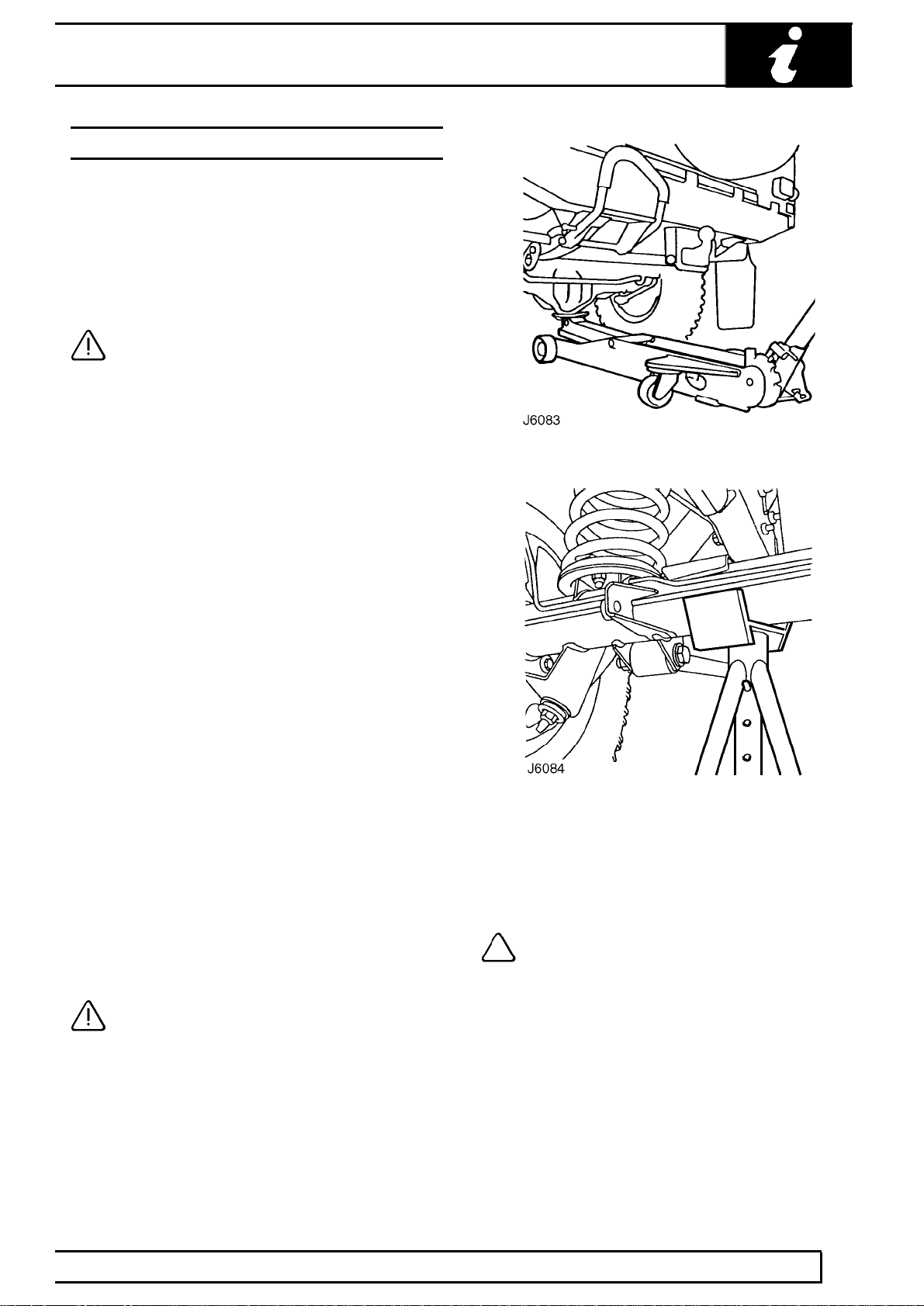
JACKING
The following instructions must be carried out before
raising the vehicle off the ground.
1. Use a solid level ground surface.
2. Apply parking brake.
3. Select 1st gear in main gearbox.
4. Select Low range in transfer gearbox.
CAUTION: To avoid damage occurring to
the under body components of the vehicle
the following jacking procedures must be
adhered to.
DO NOT POSITION JACKS OR AXLE STANDS
UNDER THE FOLLOWING COMPONENTS.
Body structure
Bumpers
Fuel lines
Brake lines
Front radius arms
Panhard rod
Steering linkage
Rear Trailing links
Fuel tank
Engine sump
Gearbox bell housing
INTRODUCTION
Jack or support vehicle by axles only.
Vehicle jack
The jack provided with the vehicle is only intended to
be used in an emergency, for changing a tyre. Do
NOT use the jack for any other purpose. Refer to
Owner’s Manual for vehicle jack location points and
procedure. Never work under a vehicle supported by
the vehicle jack.
Hydraulic jack
A hydraulic jack with a minimum 1500 kg, 3,300 lbs
load capacity must be used, see illustration J6083.
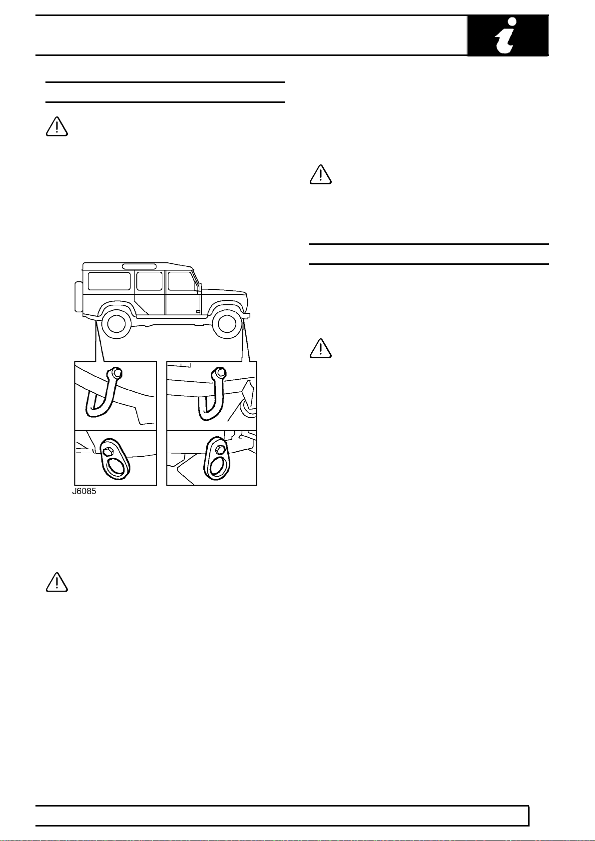
CAUTION: Do not commence work on the
underside of the vehicle until suitable axle
stands have been positioned under the
axle, see J6084.
Raise the front of the vehicle
1. Position cup of hydraulic arm under differential
casing.
NOTE: The differential casing is not
central to the axle. Care should be taken
when raising the front road wheels off the
ground as the rear axle has less sway stiffness.
2. Raise front road wheels to enable an axle stand
to be installed under left hand axle tube.
INFORMATION
5
Page 13

01
INTRODUCTION
3. Position an axle stand under right hand axle
tube, carefully lower jack until axle sits securely
on both axle stands, remove trolley jack.
4. Before commencing work on underside of
vehicle re-check security of vehicle on stands.
5. Reverse procedure when removing vehicle from
stands.
Raise rear of vehicle
1. Position cup of hydraulic arm under differential
casing.
2. Raise vehicle to enable axle stands to be
installed under left and right hand axle tubes.
3. Lower jack until axle sits securely on axle
stands, remove trolley jack.
4. Before commencing work on underside of
vehicle re-check security of vehicle on stands.
5. Reverse procedure when removing vehicle from
stands.
HYDRAULIC VEHICLE RAMP (FOUR POST)
Use only a ’drive on’ type ramp which supports vehicle
on its road wheels. If a ’wheel-free’ condition is
required, use a ’drive on’ ramp incorporating a
’wheel-free’ system providing support beneath axle
casings. Alternatively, place vehicle on a firm, flat floor
and support on axle stands.
DYNAMOMETER TESTING
The front and rear axles cannot be driven
independently.
WARNING: DO NOT attempt to drive
individual wheels with vehicle supported
on floor jacks or stands.
Four wheel dynamometers
Provided that front and rear dynamometer rollers are
rotating at identical speeds and that normal workshop
safety standards are applied, there is no speed
restriction during testing except any that may apply to
the tyres.
Two wheel dynamometers
IMPORTANT: Use a four wheel dynamometer for
brake testing if possible.
If brake testing on a single axle rig is necessary it
must be carried out with propeller shaft to rear axle
removed, AND neutral selected in BOTH main
gearbox and transfer gearbox. When checking brakes,
run engine at idle speed to maintain servo vacuum.
If checking engine performance, the transfer box must
be in high range and propeller shaft to stationary axle
must be removed.
TWO POST VEHICLE RAMPS
The manufacturer of LAND ROVER VEHICLES
DOES NOT recommend using ’Two Post’ ramps
that employ four adjustable support arms. These
are NOT considered safe for Land Rover vehicles.
If vehicle is installed on a Two Post ramp
responsibility for safety of vehicle and personnel
performing service operations is in the hands of
the Service Provider.
INFORMATION
6
Page 14
INTRODUCTION
TOWING
CAUTION: The vehicle has permanent
four-wheel drive. The following towing
instructions must be adhered to:
Towing the vehicle on all four wheels with driver
operating steering and brakes.
1. Turn ignition key to position ’1’ to release
steering lock.
2. Select neutral in main gearbox and transfer
gearbox.
Rear suspended tow by breakdown vehicle
1. If the front axle is to be trailed turn ignition key to
position ’1’ to release steering lock.
2. Select neutral in main gearbox and transfer box.
CAUTION: The steering wheel and/or
linkage must be secured in a straight
ahead position. DO NOT use the steering
lock mechanism for this purpose.
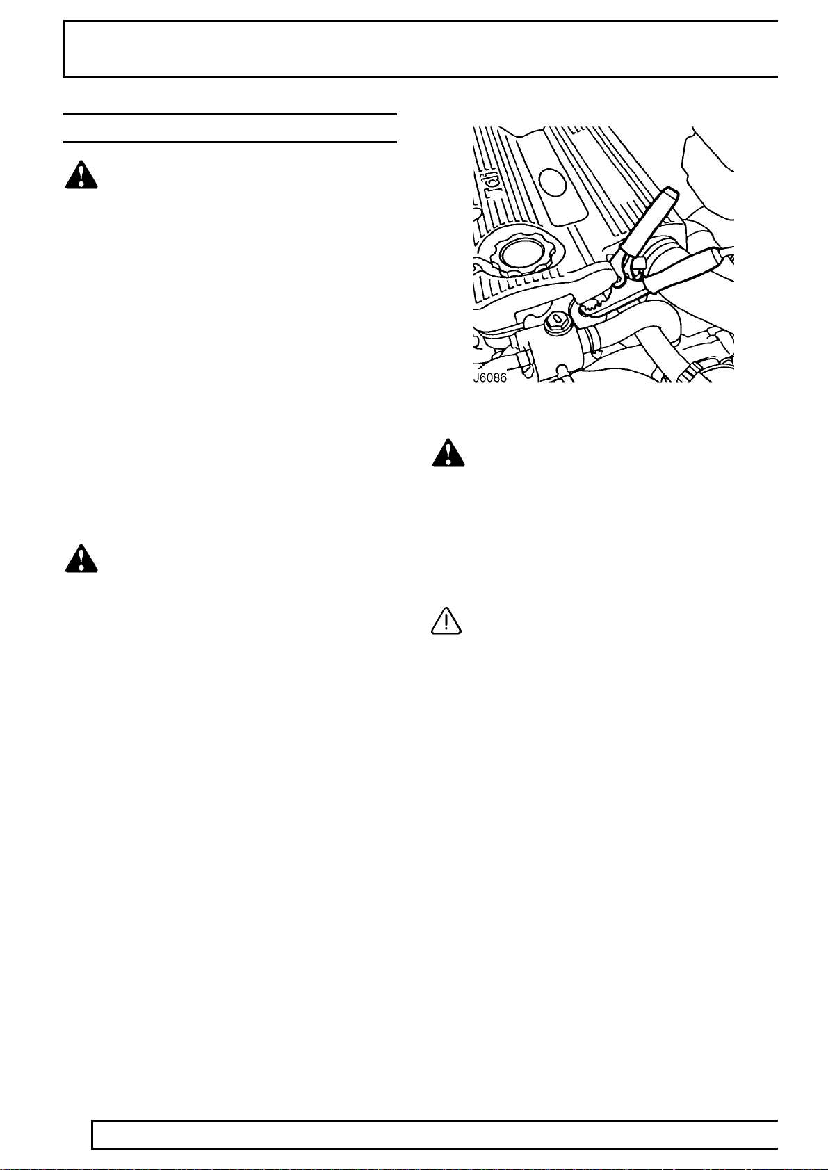
TRANSPORTING THE VEHICLE BY TRAILER
Lashing/towing eyes are provided on front and rear of
the chassis side members, see J6085, to facilitate the
securing of the vehicle to a trailer or other means of
transportation.
CAUTION: Underbody components must
not be used as lashing points.
Install vehicle on trailer and apply park brake. Select
neutral in main gearbox.
3. Secure tow rope, chain or cable to front towing
eyes (alternative types shown).
4. Release the parking brake.
CAUTION: The brake servo and power
assisted steering system will not be
functional without the engine running.
Greater pedal pressure will be required to apply
the brakes, the steering system will require
greater effort to turn the front road wheels.
The vehicle tow connection should be used only
in normal road conditions, ’snatch’ recovery
should be avoided.
INFORMATION
7
Page 15
01
JUMP STARTING
flames, sparks or lighted tobacco are brought
near battery. When charging or using a battery in
an enclosed space, always provide ventilation and
shield your eyes.
Keep out of reach of children. Batteries contain
sulphuric acid. Avoid contact with skin, eyes, or
clothing. Also, shield eyes when working near
battery to protect against possible splashing of
acid solution. In case of acid contact with skin,
eyes, or clothing, flush immediately with water for
a minimum of fifteen minutes. If acid is swallowed,
drink large quantities of milk or water, followed by
milk of magnesia, a beaten egg, or vegetable oil.
SEEK MEDICAL AID IMMEDIATELY.
To Jump Start - Negative Ground Battery
INTRODUCTION
WARNING: Hydrogen and oxygen gases
are produced during normal battery
operation. This gas mixture can explode if
WARNING: To avoid any possibility of
injury use particular care when connecting
a booster battery to a discharged battery.
WARNING: Making final cable connection
could cause an electrical arc which if
made near battery could cause an
explosion.
3. If booster battery is installed in another vehicle,
start engine and allow to idle.
4. Start engine of vehicle with discharged battery,
following starting procedure in Owners’ Manual.
1. Position vehicles so that jump leads will reach,
ensuring that vehicles DO NOT TOUCH,
alternatively a fully charged slave battery may be
positioned on floor adjacent to vehicle.
2. Ensuring that ignition and all electrical
accessories are switched off, that parking brake
is applied and neutral is selected, connect the
jump leads as follows;
A. Connect one end of first jumper cable to positive
(+) terminal of booster battery.
B. Connect other end of first jumper cable to positive
(+) terminal of discharged battery.
C. Connect one end of second jumper cable to
negative terminal of booster battery.
D. Connect other end of second jumper cable to a
good earth point on the disabled vehicle (eg. engine
front lifting eye, as shown in J6086), NOT TO
NEGATIVE TERMINAL OF DISCHARGED
BATTERY. Keep jumper lead away from moving
parts, pulleys, drive belts and fan blade assembly.
CAUTION: If vehicle fails to start within a
maximum time of 12 seconds, switch
ignition off and investigate cause. Failing
to follow this instruction could result in
irrepairable damage to catalyst, if fitted.
5. Remove negative (-) jumper cable from the
engine and then terminal of booster battery.
6. Remove positive (+) jumper cable from positive
terminals of booster battery and discharged
battery.
INFORMATION
8
Page 16

ABBREVIATIONS AND SYMBOLS USED IN THIS MANUAL
INTRODUCTION
Across flats (bolt size) AF............................................
After bottom dead centre ABDC...................................
After top dead centre ATDC.........................................
Alternating current a.c..................................................
Ampere amp................................................................
Ampere hour amp hr....................................................
Before bottom dead centre BBDC................................
Before top dead centre BTDC......................................
Bottom dead centre BDC.............................................
Brake horse power bhp................................................
British Standards BS....................................................
Carbon monoxide CO..................................................
Centimetre cm.............................................................
Centigrade (Celsius) C................................................
Cubic centimetre cm
Cubic inch in
...................................................
...............................................................
Degree (angle) deg or °...............................................
Degree (temperature) deg or °.....................................
Diameter dia................................................................
Direct current d.c..........................................................
Electronic Control Unit ECU........................................
Fahrenheit F.................................................................
Feet ft...........................................................................
Feet per minute ft/min..................................................
Fifth 5th........................................................................
First 1st........................................................................
Fluid ounce fl oz..........................................................
Foot pounds (torque) lbf.ft............................................
Fourth 4th.....................................................................
Gramme (force) gf........................................................
Gramme (mass) g........................................................
Gallons gal...................................................................
High tension (electrical) H.T.........................................
Internal diameter I.D....................................................
Inches of mercury in. Hg..............................................
Inches in......................................................................
Kilogramme (force) kgf.................................................
Kilogramme (mass.) kg................................................
Kilogramme centimetre (torque) kgf.cm.......................
Kilogramme per square millimetre kgf/mm
Kilogramme per square centimetre kgf/cm
.................
.................
Kilogramme metres (torque) kgf.m..............................
Kilometres km..............................................................
Kilometres per hour km/h.............................................
Kilovolts kV...................................................................
Left-hand LH................................................................
Left-hand steering LHStg.............................................
Left-hand thread LHThd...............................................
Litres litre.....................................................................
Low tension l.t..............................................................
Maximum max.............................................................
Metre m........................................................................
Millilitre ml....................................................................
Millimetre mm...............................................................
Miles per gallon mpg....................................................
Miles per hour mph......................................................
Minute (angle) ’............................................................
Minus (of tolerance) -...................................................
Negative (electrical) -...................................................
Newton metres (torque) Nm........................................
Number No..................................................................
Ohms ohm...................................................................
Ounces (force) ozf.......................................................
3
Ounces (mass) oz........................................................
3
Outside diameter O.D..................................................
Part number Part No....................................................
Percentage %...............................................................
Pints pt.........................................................................
Plus (tolerance) +.........................................................
Positive (electrical) +....................................................
Pound (force) lbf..........................................................
Pounds inch (torque) lbf.in...........................................
Pound (mass) lb...........................................................
Pounds per square inch P.S.I......................................
Ratio :...........................................................................
Reference ref...............................................................
Revolution per minute rev/min.....................................
Right-hand RH.............................................................
Second (angle) "...........................................................
Second (numerical order) 2nd......................................
Specific gravity sp.gr....................................................
Square centimetres cm
Square inches in
...............................................
.........................................................
Standard wire gauge s.w.g..........................................
Synchroniser/Synchromesh synchro...........................
Third 3rd.......................................................................
Top dead centre TDC..................................................
United Kingdom UK......................................................
2
Vehicle Identification Number VIN...............................
2
Volts V.........................................................................
Watts W.......................................................................
SCREW THREADS
British Standard Pipe BSP...........................................
Unified Coarse UNC....................................................
Unified Fine UNF.........................................................
2
2
INFORMATION
9
Page 17

01
CROSS REFERENCE OF EMISSION SYSTEM TERMINOLOGY
INTRODUCTION
NEW TERM (ACRONYM)
Accelerator pedal (AP).................................................
Air cleaner (ACL)..........................................................
Air conditioning (A/C)...................................................
Battery positive voltage (B+)........................................
Closed loop (CL)..........................................................
Closed throttle position (CTP)......................................
Canister purge valve (CANPV)....................................
Data link connector (DLC)...........................................
Diagnostic trouble code (DTC).....................................
Distributor ignition (DI).................................................
Engine control module (ECM)......................................
Engine coolant level (ECL)...........................................
Engine coolant temperature (ECT)..............................
Engine speed (RPM)....................................................
Evaporative emission system (EVAP)..........................
Engine fuel temperature sensor (EFTS)......................
4th gear, 3rd gear etc. (4GR, 3GR)..............................
Fuel pump (FP)............................................................
Fan control module (FCM)...........................................
Generator (GEN)..........................................................
Ground (GND)..............................................................
Heated oxygen sensor (H02S)....................................
Idle air control (IAC)......................................................
Idle air control valve (IACV).........................................
Ignition control module (ICM).......................................
Intake air temperature (IAT).........................................
Manifold vacuum zone (MVZ)......................................
Mass air flow sensor (MAF).........................................
Open loop (OL)............................................................
Relay module (RM)......................................................
Solid state relay module (SSRM).................................
Three way catalytic converter (TWC)..........................
Throttle body (TB)........................................................
Throttle position sensor (TP)........................................
Transmission range (TR)..............................................
Wide open throttle (WOT)............................................
OLD TERM (ACRONYM)
Throttle pedal (-)..........................................................
Air cleaner (-)...............................................................
Air conditioning (AC)....................................................
Battery plus, bat +, bat feed (B+).................................
Closed loop (-).............................................................
Closed throttle, idle position (-)....................................
Charcoal canister purge valve (-).................................
Serial link (-)................................................................
Fault code (-)...............................................................
Electronic ignition (-)....................................................
Electronic control unit (ECU)........................................
Coolant level (-)...........................................................
Coolant temperature (temp).........................................
Coolant temperature thermistor (-)..............................
Engine speed (rev/min)................................................
Evaporative loss system (ELC)...................................
Fuel temperature thermistor (-)....................................
Fourth gear, 3rd gear (-)..............................................
Fuel pump (-)...............................................................
Condenser fan timer (-)................................................
Alternator (-)................................................................
Ground, earth (B-)........................................................
Lambda (02) sensor (-)................................................
Idle speed control (ISC)................................................
Stepper motor (-).........................................................
Ignition module (-)........................................................
Intake temperature/ambient temperature (-)................
Manifold depression, vacuum (-).................................
Air flow meter (-)..........................................................
Fault code display unit (-)............................................
Open loop (-)...............................................................
Relay (-).......................................................................
Control unit (-)..............................................................
Catalyst, catalytic converter (CAT)..............................
Throttle housing (-)......................................................
Transmission gear (-)...................................................
Full throttle, wide open throttle (WOT).........................
10
INFORMATION
Page 18
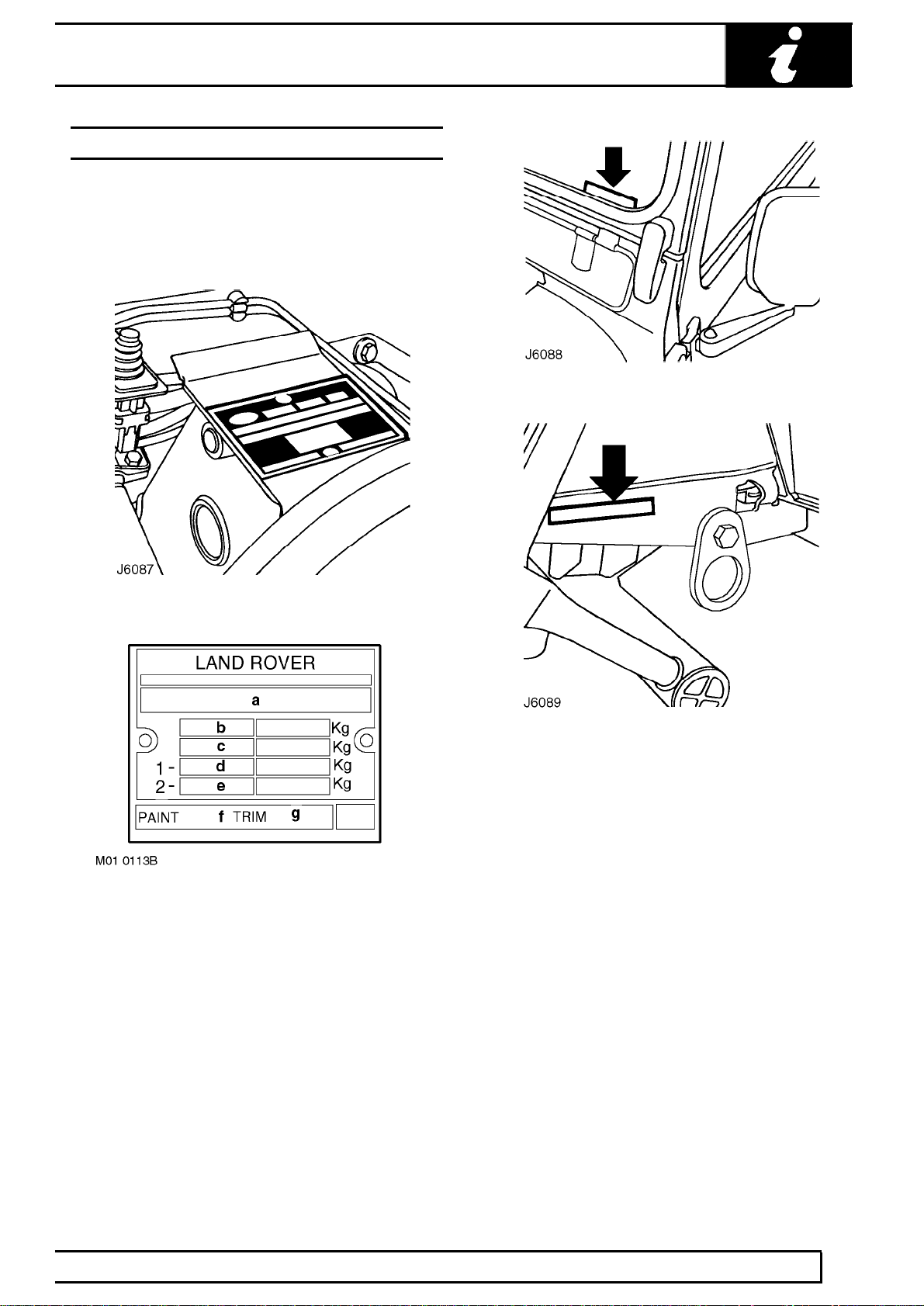
VEHICLE IDENTIFICATION NUMBER (VIN)
The Vehicle Identification Number and the
recommended maximum vehicle weights are stamped
on a plate riveted to the brake pedal box in the engine
compartment. The VIN is also stamped on a plate
visible through the LH side of the windscreen.
INTRODUCTION
a. Identification
b. Maximum permitted laden weight for vehicle
c. Maximum vehicle and trailer weight
d. Maximum road weight-front axle
e. Maximum road weight-rear axle
f. Paint code
g. Trim level
The number is also stamped on the RH side of the
chassis to the rear of the front lashing eye, see J6089.
The Vehicle Identification Number identifies the
manufacturer, model range, wheel base, body type,
engine, steering, transmission, model year and place
of manufacture. The following example shows the
coding process.
SAL LD H M 8 7 X A
SAL = World manufacturer identifier
LD = Land Rover Defender
H = 110 inch, V= 90inch, K= 130 inch
M = 4 door Station Wagon, A= 90 Soft Top, Hard Top,
Pick-up, B= 2 door Station Wagon, E= 2 door 130
Crew cab, F= 4 door 130 Crew cab, H= 130 High
Capacity Pick-up
8= Td5 engine.
7= RH drive, 5 speed manaul, 8= LH drive, 5 speed
manual
X= 1999 MY, volume build.
A= Solihull build, F= CKD, assembled locally from kit
INFORMATION
11
Page 19
01
INTRODUCTION
LOCATION OF IDENTIFICATION NUMBERS
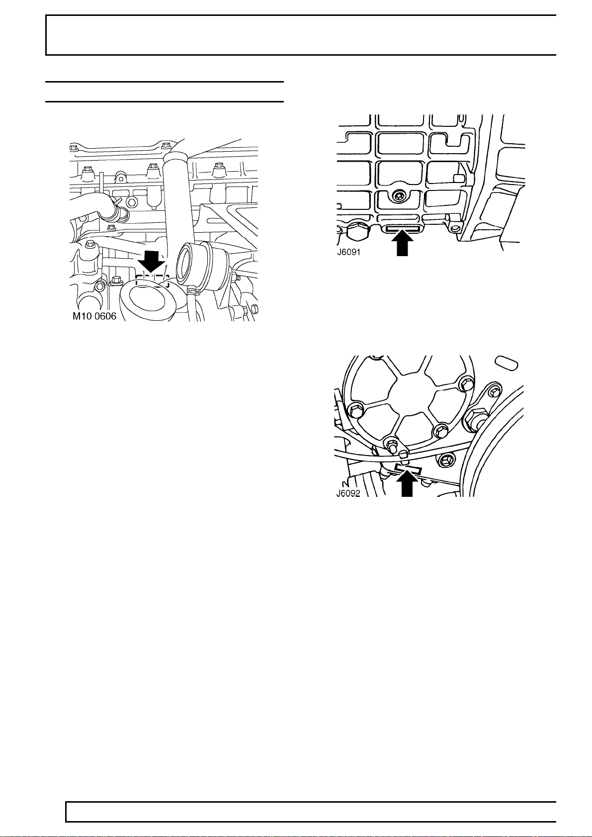
Engine serial number - Td5 Engine
The Td5 engine number is stamped on the LH side of
the cylinder block, below the exhaust manifold.
Main gearbox R380 serial number
Stamped on a cast pad on the bottom RH side of the
gearbox.
Transfer gearbox LT230 serial number
12
The serial number is stamped on the LH side of the
gearbox casing below the mainshaft rear bearing
housing adjacent to the bottom cover.
INFORMATION
Page 20
INTRODUCTION
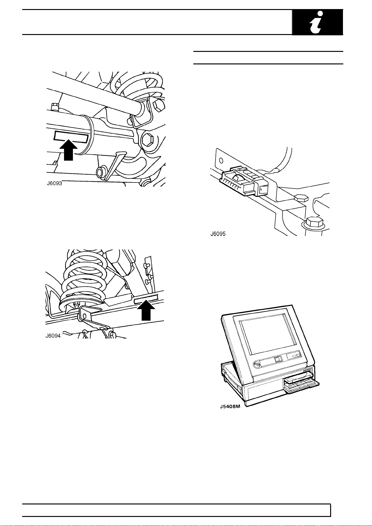
Front axle serial number
Stamped on the front of LH axle tube, inboard of
radius arm mounting bracket.
Rear axle serial number
FAULT DIAGNOSTIC EQUIPMENT
TESTBOOK
For Defender models fitted with the vehicle Anti-theft
Immobilisation and Alarm System, diagnostic
equipment, named TestBook, is available to assist in
the diagnostic and fault finding abilities of the Dealer
workshop. A diagnostic connector, located under the
front centre seat, or cubby box, as shown below, is
provided to facilitate the procedures.
Stamped on the rear of LH axle tube, inboard of
spring mounting.
If an exhaust gas recirculation (EGR) system is fitted,
this too can be checked using TestBook. A diagnostic
connector, also located under the front centre seat or
cubby box, is provided.
Features of Testbook include :-
Fully upgradable support for the technician.
Structured diagnostics to accommodate all skill levels.
Touch screen operation.
Direct print out of screen information and test results.
INFORMATION
13
Page 21

01
READING THIS SUPPLEMENT
This Supplement is divided into sections shown on the
contents page, alongside a range of icons, familiar to
service technicians.
Relevant information is contained within each of these
sections. These are further divided into the following
sub-sections which appear at the foot of each page :-
Description and operation.
Adjustment.
Repair.
Overhaul.
To avoid repeating information through the sections,
where part of the repair operation impacts on another
section, a cross reference is given to direct the reader
to where the information is sited.
INTRODUCTION
For example:
The maintenance section states the need to renew
drive belt. A cross reference sites this information in:
Section 12 Engine
- Sub-section: Repair
14
INFORMATION
Page 22

04 - GENERAL SPECIFICATION DATA
CONTENTS
Page
INFORMATION
ENGINE - Td5 1......................................................................................................
FUEL SYSTEM - Td5 3...........................................................................................
COOLING SYSTEM - Td5 3....................................................................................
CLUTCH - Td5 3.....................................................................................................
TRANSMISSION - Td5 4.........................................................................................
STEERING 5...........................................................................................................
SUSPENSION 6......................................................................................................
ROAD SPRING DATA 6..........................................................................................
SHOCK ABSORBERS 7.........................................................................................
BRAKES 7...............................................................................................................
AIR CONDITIONING 8............................................................................................
WIPER MOTORS 8.................................................................................................
ELECTRICAL 8.......................................................................................................
BULBS 9.................................................................................................................
VEHICLE WEIGHTS AND PAYLOAD 10................................................................
TOWING WEIGHTS 11...........................................................................................
OFF-ROAD PERFORMANCE 11............................................................................
TYRE SIZE AND PRESSURES 12.........................................................................
WHEELS 12............................................................................................................
VEHICLE DIMENSIONS 13....................................................................................
Page 23

Page 24

GENERAL SPECIFICATION DATA
ENGINE - Td5
Type 2.5 litre in-line direct injection Diesel, turbocharged.................................................................................
Number of cylinders 5 in-line, No. 1 cylinder at front of engine.........................................................
Bore 84.450 mm (3.3248 in).................................................................................
Stroke 88.950 mm (3.5020 in)...............................................................................
Capacity 2498 cm3(152.5 in3)...........................................................................
Firing order 1 - 2 - 4 - 5 - 3.......................................................................
Compression ratio 19.5:1............................................................
Direction of rotation Clockwise viewed from the front of the engine...........................................................
Dimensions
Length 766 mm (30.1 in).....................................................................
Width 708 mm (27.8 in).......................................................................
Height 788 mm (31.0 in)......................................................................
Emissions standard :-
Engine Serial No. Prefixes 10P to 14P - EU2 Model ECD 2........
Engine Serial No. Prefixes 15P to 19P - EU3 Model ECD 3........
Lubrication
and intercooled
Type Wet sump, pressure fed.................................................................................
Pump type Eccentric rotor, crankshaft driven integral with stiffener........................................................................
Filter type:
Primary Centrifuge filter....................................................................
Secondary Disposable canister with full flow by-pass...............................................................
Pressure at idle (cold) 3.0 bar (43.5 lbf.in2)......................................................
Pressure at 3500 rev/min (hot) 1.5 - 3.0 bar (21.75 - 43.5 lbf.in2).........................................
Relief valve opening pressure 4.0 bar (58 lbf.in2)..........................................
Low oil pressure switch opening pressure 0.2 - 0.6 bar (3.0 - 8.8 lbf.in2).......................
Crankshaft
Main bearing journal diameter 61.9875 - 62.0125 mm..........................................
Crankpin journal diameter 53.99 - 54.01 mm................................................
Crankshaft end float 0.020 - 0.250 mm.........................................................
Main bearings
Number and type 6 half shells (5 main, 1 thrust)..............................................................
Pistons
Type Graphite compound skirt with combustion chamber in.................................................................................
Clearance in cylinder bore 0.172 - 0.206 mm (measured at bottom of skirt, 90° to...............................................
Diameter 84.270 - 85.254 mm (measured 90° to gudgeon pin,..........................................................................
plate.
crown.
gudgeon pin)
and 40.00 mm from bottom of skirt.)
INFORMATION
1
Page 25

04
Gudgeon pins
Type Fully floating, offset towards piston thrust side..................................................................................
Piston rings
Type
Upper compression Barrel edge, chrome plated.................................................
Lower compression Taper faced.................................................
Oil control Bevelled ring with spring................................................................
New ring to groove clearance
Upper compression Not measured.................................................
Lower compression 0.050 - 0.082 mm (0.002 - 0.003 in).................................................
Oil control 0.050 - 0.082 mm (0.002 - 0.003 in)................................................................
Piston ring fitted gap in cylinder bore
Upper compression 0.30 - 0.45 mm (0.0118 - 0.0177 in).................................................
Lower compression 0.40 - 0.60 mm (0.0157 - 0.0236 in).................................................
Oil control 0.25 - 0.40 mm (0.0098 - 0.0157 in)................................................................
GENERAL SPECIFICATION DATA
Camshaft
Drive Duplex chain.................................................................................
End float 0.6 - 0.16 mm...........................................................................
Number of bearings 6..........................................................
Tappets
Type Hydraulic lash adjusters with followers.................................................................................
Valves
Stem diameter
Exhaust 6.905 ± 0.008 mm (0.271 ± 0.0003 in)...................................................................
Inlet 6.915 ± 0.008 mm (0.272 ± 0.0003 in).........................................................................
Head diameter
Exhaust 31.7 mm (1.25 in)...................................................................
Inlet 34.7 mm (1.37 in).........................................................................
Seat face angle
Exhaust 45°...................................................................
Inlet 30°.........................................................................
Valve face angle
Exhaust 44°48’ ± 12’...................................................................
Inlet 29°48’ ± 12’.........................................................................
Valve springs
Type Parallel, single coil.................................................................................
INFORMATION
2
Page 26

GENERAL SPECIFICATION DATA
FUEL SYSTEM - Td5
Type Direct injection from pressure regulated supply with.................................................................................
Pressure regulator setting 4 bar (58 lbf.in2)................................................
Pump Electric two stage submersible................................................................................
Pump output
Low pressure 30 l/h (6.6 gal/h) at 0.5 bar (7.25 lbf.in2)..........................................................
High pressure 180 l/h (39.6 gal/h) at 4 bar (58 lbf.in2)..........................................................
Max consumption 30 l/h (6.6 gal/h).............................................................
Injectors Electronic unit injectors...........................................................................
Injector normal operating pressure 1500 bar (21750 lbf.in2)..................................
Filter In-line canister filter/water separator with water.................................................................................
COOLING SYSTEM - Td5
Type Pressurised spill return partial flow, thermostatically.................................................................................
Cooling fans 11 blade axial flow on viscous coupling and 11 blade.....................................................................
Electric cooling fan switching points
On Vehicle speeds of 50 mph (80 km/h) and below while...........................................................................
Off Vehicle speeds of 62.5 mph (100 km/h) and above or...........................................................................
Coolant pump Centrifugal impeller, belt driven from crankshaft...................................................................
Thermostat Waxstat with pressure relief valve.......................................................................
Thermostat opening temperature
Initial opening 82°C (179°F)..........................................................
Fully open 96°C (204°F)...............................................................
Expansion tank cap relief valve operating pressure 1.4 bar (20.3 lbf.in2).........
cooled return flow
detection
controlled
axial flow electric
ambient temperature is 28°C (82°F) or above
ambient temperatures of 25°C (77°F) and below
CLUTCH - Td5
Type Diaphragm spring, hydraulically operated with.................................................................................
Drive plate diameter 267 mm.........................................................
Pressure plate diameter 270 mm...................................................
self-centering pre-loaded release bearing
INFORMATION
3
Page 27

04
TRANSMISSION - Td5
Main gearbox
Type R380 Single helical constant mesh.......................................................................
Speeds 5 forward, 1 reverse, all synchromesh.............................................................................
Transfer box
Type LT230TE Two speed reduction on main gearbox output. Front.................................................................
Rear axle
Type Spiral bevel, fully floating shafts.................................................................................
Ratio 3.54:1.................................................................................
Front axle
GENERAL SPECIFICATION DATA
and rear drive permanently engaged via a lockable
differential
Type Spiral bevel, enclosed constant velocity joints, fully.................................................................................
Ratio 3.54:1.................................................................................
Propeller shafts
Type, front and rear Tubular 51 mm dia...........................................................
Universal joints Open type Hookes O3EHD.................................................................
floating shafts, 32° angularity of universal joint on full
lock
INFORMATION
4
Page 28

GENERAL SPECIFICATION DATA
STEERING
Power steering box
Make/type Adwest Varamatic - worm and roller box........................................................................
Ratio Variable: straight ahead 19.3:1 on lock 14.3:1.................................................................................
Steering wheel turns, lock-to-lock 3.375....................................
Steering pump
Make/type Hobourn-Eaton series 500........................................................................
Steering geometry
Steering wheel diameter 412 mm (16.22 in)..................................................
Toe-out measurement 0 to 2 mm toe out......................................................
Toe-out included angle 0° to 0° 20’.....................................................
Camber angle 0° *..................................................................
Castor angle 3° *.....................................................................
Swivel pin inclination static 7° *...............................................
* Check with vehicle on level ground, in unladen
condition and five gallons of fuel. Rock the front of the
vehicle up and down to allow it to take up a normal
static position.
Turning circle between kerbs
90 models:
265/75 x 16 tyres 12,65 m (41.5 ft)..............................................................
All other tyres 11,70 m (38.4 ft)...................................................................
110 models:
750 x 16 tyres 13,41 m (44 ft)..................................................................
130 models:
750 x 16 tyres 15,24 m (50 ft)..................................................................
INFORMATION
5
Page 29

04
SUSPENSION
Type Coil springs controlled by telescopic dampers front.................................................................................
Front Transverse location of axle by Panhard rod, and fore.................................................................................
Rear Fore and aft movement inhibited by two tubular trailing.................................................................................
ROAD SPRING DATA
90 (2400 Kg) Part No. Colour Code
Front - Driver’s side NRC 9446 Blue/green
Front - Passenger side NRC 9447 Blue/yellow
Rear - Driver’s side NRC 9448 Blue/red
Rear - Passenger side NRC 9449 Yellow/white
GENERAL SPECIFICATION DATA
and rear.
and aft location by two radius arms. Anti-roll bar fitted
as standard on 90 models with 265/75 tyres and 130
models.
links. Lateral location of axle by a centrally positioned
’A’ frame, upperlink assembly, bolted at the apex to a
ball joint mounting. Anti-roll bar fitted as standard on
90 models with 265/75 tyres, 110 models with self
levelling unit, and 130 models.
90 (2550 Kg)
Front - Driver’s side NRC 9446 Blue/green
Front - passenger side NRC 9447 Blue/yellow
Rear - Driver’s side NRC 9462 Green/yellow/red
Rear - Passenger side NRC 9463 Green/yellow/white
110 (3050 Kg)
Front - both sides NRC 8045 Yellow/yellow
Rear - both sides NRC 6904 Red/green
110 Levelled (2950 Kg)
Front - both sides NRC 8045 Yellow/yellow
Rear - both sides NRC 7000 Green/white
110 (3400 Kg)
Front - both sides NRC 8045 Yellow/yellow
Rear - both sides NRC 6904 Red/green
Rear helper springs - both sides RRC 3266 No colour code
110 (3600 Kg)
Front - Driver’s side NRC 9448 Blue/red
Front - passenger side NRC 9449 Yellow/white
Rear - both sides NRC 6904 Red/green
Rear helper springs - both sides RRC 3226 No colour code
130 (3500 Kg)
Front - driver’s side NRC 9448 Blue/red
Front - passenger side NRC 9449 Yellow/white
Rear - driver’s side NRC 6389 Red/red
Rear - passenger side NRC 6904 Red/green
Front/rear helper springs - both sides RRC 3266 No colour code
INFORMATION
6
Page 30

GENERAL SPECIFICATION DATA
SHOCK ABSORBERS
Type Telescopic, double-acting non-adjustable.................................................................................
Bore diameter 35.47mm...................................................................
BRAKES
Front brake
Caliper AP Lockheed, four opposed pistons..............................................................................
Operation Hydraulic, self adjusting.........................................................................
Disc 90 - Solid, outboard, 110/130 - Ventilated, outboard..................................................................................
Disc diameter 298 mm (11.73 in)...................................................................
Disc thickness 90 - 14,1 mm (0.56in), 110/130 - 24mm (0.95 in)..................................................................
Wear limit 1 mm (0.04in) per side of disc.........................................................................
Disc run-out maximum 0,15mm (0.006 in).....................................................
Pad area 58 cm2(9.0 in2)..........................................................................
Total swept area 801,3 cm2(124.2 in2)...............................................................
Pad material Ferodo 3440 non asbestos.....................................................................
Pad minimum thickness 3 mm (0.12in)...................................................
Rear brake
Caliper AP Lockheed opposed piston..............................................................................
Operation Hydraulic, self adjusting.........................................................................
Disc Solid, outboard..................................................................................
Disc diameter 90 - 290 mm (11.42 in), 110/130 - 298 mm (11.73)...................................................................
Disc thickness 90 - 12,5 mm (0.49 in), 110/130 - 14,1 mm (0.56 in)..................................................................
Wear limit 90 - 0,38 mm (0.015 in), 110/130 - 1,0 mm (0.04 in).........................................................................
Disc run-out maximum 0,15 mm (0.006 in).....................................................
Pad area 90 - 30,5 cm2(4.37 in2), 110/130 - 36,2 cm2(5.61 in2)..........................................................................
Total swept area 90 - 694 cm2(106.98 in2)...............................................................
Pad material Ferodo 3440 non asbestos.....................................................................
Pad minimum thickness UP TO 02MY - 3 mm (0.12 in)...................................................
Pad minimum thickness From 02MY - 2 mm (0.08 in)...................................................
Parking brake
Type Mechanical, cable operated drum brake on the rear of.................................................................................
Drum internal diameter 254 mm (10.0 in).....................................................
Width 70 mm (2.75 in)................................................................................
Pad material Ferodo 3611 non asbestos.....................................................................
Servo/master cylinder
per side of disc
the transfer gearbox output shaft
Manufacturer Lucas....................................................................
Servo type LSC 80........................................................................
Master cylinder type 25,4 mm (1.0 in) diameter, tandem.........................................................
Pressure reducing valve, failure conscious Cut-in pressure, 90 - 24 bar (360 Ibf/in2) ratio 4.0:1,......................
NOTE: * Pressure reducing valves are not fitted to all 110 specifications.
110 - 43 bar (645 Ibf/in2) ratio 2.9:1*
INFORMATION
7
Page 31

04
AIR CONDITIONING
System CFC free, expansion valve system.............................................................................
Compressor Nippon Denso.....................................................................
Refrigerant R134a CFC free.......................................................................
Charge quantity 750 g ± 50 g................................................................
Refrigerant oil ND-OIL 8...................................................................
WIPER MOTORS
Tailgate wiper motor
Make/type IMOS (non-serviceable)........................................................................
Running current, wet screen at 20°C ambient 1.0 to 2.8 amps.................
Wiper speed, wet screen at 20°C ambient 37 to 43 cycles per minute.......................
Windscreen wiper motor
GENERAL SPECIFICATION DATA
Make/type Lucas 14W uprated two speed........................................................................
Armature end float 0,1 to 0,2 mm............................................................
Brush length, minimum 4,8 mm....................................................
Brush spring tension 140 to 200 g........................................................
Resistance of armature winding
at 16˚C (69˚F) measured between adjacent
commutatator segments 0.23 to 0.35 ohms...................................................
Light running, rack disconnected: current at 13.5 V 2.0 amps.........
Wiper speed, wet screen, 60 seconds from cold Low speed - 45 ± 3 rev/min, High speed - 65 ± 5..............
ELECTRICAL
System 12 volt, negative ground.............................................................................
Battery
Make/type Delphi GP31........................................................................
Alternator
Type Nippon Denso.................................................................................
rev/min
Fuses
Type Autofuse (blade type) blow ratings to suit individual.................................................................................
Horns
Make/type Mixo TR99........................................................................
Starter motor
Make and type Bosch 12v.................................................................
INFORMATION
8
circuits
Page 32

GENERAL SPECIFICATION DATA
BULBS
REPLACEMENT BULBS TYPE
Headlamps 12V 60/55W Halogen
Front side lamps 12V 5W
Side repeater lamps 12V 5W
Tail lamps 12V 21W
Cente High Mounted Stop Lamp 12V 21W
Direction indicator lamps 12V 21W
Number plate lamp 12V 4W
Reverse lamp 12V 21W
Rear fog guard lamp 12V 21W
Interior roof lamps 12V 10W
Instrument illumination 12V 1.2W
Warning light panel 12V 1.2W
Hazard warning switch 12V 1.2W
CAUTION: The fitting of new bulbs with wattages in excess of those specified will result in damage
to vehicle wiring and switches.
INFORMATION
9
Page 33

04
VEHICLE WEIGHTS AND PAYLOAD
When loading a vehicle to its maximum (Gross Vehicle Weight), consideration must be taken of the unladen
vehicle weight and the distribution of the payload to ensure that axle loadings do not exceed the permitted
maximum values.
It is the customer’s responsibility to limit the vehicle’s payload in an appropriate manner such that neither
maximum axle loads nor Gross Vehicle Weight are exceeded.
Maximum EEC kerb weight and distribution - all optional equipment
VEHICLE AXLE WEIGHTS
90 models Station Wagon Utility
Front axle 1200 Kg (2645 lb)......................................................................... 1200 Kg (2645 lb)
Rear axle 1500 kg (3307 lb).......................................................................... 1500 Kg (3307 lb)
Gross vehicle weight 2550 Kg (5291 lb)........................................................ 2400 Kg (5622 lb)
110 models Station Wagon Utility
Front axle 1200 Kg (2645 lb)......................................................................... 1200 Kg (2645 lb)
Rear axle 1750 Kg (3858 lb).......................................................................... 1850 Kg (4078 lb)
Gross vehicle weight 2950 Kg (6503 lb)........................................................ 3050 Kg (6724 lb)
GENERAL SPECIFICATION DATA
130 models Utility
Front axle 1580 Kg (3483 lb).....................................................................................................................
Rear axle 2200 Kg (4850 lb)......................................................................................................................
Gross vehicle weight 3500 Kg (7716 lb)....................................................................................................
NOTE: Axle weights are not accumulative. The individual maximum axle weights and gross vehicle
weight must not be exceeded.
EEC VEHICLE KERB WEIGHTS
90 models Standard Heavy Duty
Soft top: 1770 Kg (3402 lb)............................................................................ 1993 Kg (4393 lb)
Pick-up: 1770 Kg (3402 lb)............................................................................ 1993 Kg (4393 lb)
Hard top: 1815 Kg (4001 lb).......................................................................... 1987 Kg (4380 lb)
Station wagon: 1870 Kg - 1885 Kg................................................................. 1989 Kg - 1998 Kg
(4122 lb - 4155 lb) (4385 lb - 4404 lb)
110 models
Soft top: 1885 Kg - 2080 Kg............................................................................ (4155 lb - 4585 lb)
High capacity pick-up: 1920 Kg - 2122 Kg...................................................... (4232 lb - 4678 lb)
Hard top: 1920 Kg - 2110 Kg.......................................................................... (4232 lb - 4651 lb)
Station wagon: 2055 Kg - 2229 Kg................................................................. (4530 lb - 4914 lb)
130 models
Crew cab and high capacity pick-up: 2177 Kg - 2286 Kg...........................................................................
(4667 lb - 5039 lb)
EEC kerb weight = Unladen weight + Full fuel tank + 75 Kg (165 lb).
INFORMATION
10
Page 34

GENERAL SPECIFICATION DATA
TOWING WEIGHTS
On-road Off-road
Unbraked trailers 750 Kg (1653 lb).............................................................. 500 Kg (1102 lb)
Trailers with overrun brakes 3500 Kg (7716 lb)............................................. 1000 Kg (2204 lb)
4 wheel trailers with coupled brakes * 4000 Kg (8818 lb).............................. 1000 Kg (2204 lb)
NOTE: * Only applies to vehicles modified to accept coupled brakes.
NOTE: All weight figures are subject to local restrictions.
OFF-ROAD PERFORMANCE
90 models
Max. gradient (EEC kerb weight) 45°.....................................
Approach angle:
Soft top and Pick-up (EEC kerb weight) 48°..................
Hard top and station wagon (EEC kerb weight) 51.5°......
Departure angle
Soft top and Pick-up (EEC kerb weight) 49°..................
Hard top and Station wagon (EEC kerb weight) 53°...............
Wading depth 500 mm (20 in)...................................................................
Min. ground clearance (unladen):
Soft top and pick-up 191 mm (7.5 in).................................................
Hard top and station wagon 229 mm (9.0 in).....................................
NOTE: Departure angles do not account for the addition of a tow hitch.
110 and 130 models
Max. gradient (EEC kerb weight) 45°.....................................
Approach angle (EEC kerb weight) 50°..................................
Departure angle (EEC kerb weight)
110 models 35°......................................................................
130 models 34°......................................................................
Wading depth 500 mm (20 in)...................................................................
Min. ground clearance (unladen 215 mm (8.5 in).......................................
NOTE: Departure angles do not account for the addition of a tow hitch.
INFORMATION
11
Page 35

04
GENERAL SPECIFICATION DATA
TYRE SIZE AND PRESSURES
90 models Front Rear
Normal - all load conditions
205/80 R16 Radial 1,9 bar.................................................. 2,6 bar
28 Ibf/in
2,0 kgf/cm
2
2
38 Ibf/in
2,7 kgf/cm
2
2
265/75 R16 Radial (multi terrain) 1,9 bar.......................... 2,4 bar
28 Ibf/in
2,0 kgf/cm
2
2
7.50 R16 Radial 1,9 bar...................................................... 2,6 bar
28 Ibf/in
2,0 kgf/cm
2
2
110 models
Normal - all load conditions
7.50 R16 Radial 1,9 bar...................................................... 3,3 bar
28 Ibf/in
2,0 kgf/cm
2
2
130 models
Normal - all load conditions
7.50 R16 Radial 3,0 bar...................................................... 4,5 bar
44 Ibf/in
3,1 kgf/cm
WARNING: Tyre pressures must be
checked with the tyres cold, as the
pressure is about 0,21 bar (3 Ibf/in2, 0,2
kgf/cm2) higher at running temperature. If the
vehicle has been parked in the sun or high
ambient temperatures, DO NOT reduce the tyre
pressures, move the vehicle into the shade and
wait for the tyres to cool before checking the
2
2
WARNING: Always use the same make and
type of radial-ply tyres, front and rear. DO
NOT use cross-ply tyres, or interchange
tyres from front to rear.
• If the the wheel is marked ’TUBED’, an inner
tube MUST be fitted, even with a tubeless tyre.
• If the wheel is marked ’TUBELESS’, an inner
tube must NOT be fitted.
pressures.
35 Ibf/in
2
2,5 kgf/cm
38 Ibf/in
2
2,7 kgf/cm
48 Ibf/in
2
3,4 kgf/cm
65 Ibf/in
2
4,6 kgf/cm
2
2
2
2
WHEELS
90 models
Steel wheel size:
Heavy duty - UK and Western Europe 6.5F X 16.............................
Other markets 5.5F X 16..................................................................
Alloy wheel size 7J X 16................................................................
110 models
Steel wheel size:
Heavy duty - UK and Western Europe 6.5F X 16.............................
Other markets 5.5F X 16..................................................................
130 models
Steel wheel size:
Heavy duty - UK and Western Europe 6.5F X 16.............................
Other markets 5.5F X 16..................................................................
INFORMATION
12
Page 36

GENERAL SPECIFICATION DATA
VEHICLE DIMENSIONS
90 models
Overall length:
Soft top and Pick-up 3722 mm (146.5 in)................................................
Hard top and Station wagon 3883 mm (152.9 in)....................................
Overall width: 1790 mm (70.5 in)...................................................................
Overall height:
Soft top 1965 mm (77.4 in)....................................................................
Pick-up and Station wagon 1963 mm (77.3 in)......................................
Hard top 1972 mm (77.6 in)...................................................................
Wheelbase 2360 mm (92.9 in).......................................................................
Track front/rear 1486 mm (58.5 in).................................................................
Width between wheel boxes 925 mm (36.4 in)............................................
110 models
Overall length:
Soft top and Pick-up 4438 mm (175 in)................................................
High capacity pick-up 4631 mm (182 in)..............................................
Hard top/Station and County 4599 mm (181 in)...................................
Overall width: 1790 mm (70.5 in)...................................................................
Overall height: 2035 mm (80.1 in)..................................................................
Wheelbase 2794 mm (110 in).......................................................................
Track front/rear 1486 mm (58.5 in).................................................................
Width between wheel boxes:
High capacity pick-up 1090 mm (43 in)..............................................
all other models 925 mm (36.4 in).......................................................
130 models
Overall length 5132 mm (202 in)...................................................................
Overall width 1790 mm (70.5 in)....................................................................
Overall height 2035 mm (80.1 in)...................................................................
Wheelbase 3226 mm (127 in).......................................................................
Track front/rear 1486 mm (58.5 in).................................................................
Width between wheel boxes 1090 mm (43 in)............................................
INFORMATION
13
Page 37

Page 38

05 - ENGINE TUNING DATA
CONTENTS
Page
INFORMATION
ENGINE - Td5 1......................................................................................................
HEATER PLUGS - Td5 1........................................................................................
INJECTORS - Td5 1................................................................................................
TURBOCHARGER - Td5 1.....................................................................................
Page 39

Page 40

ENGINE - Td5
Type 2.5 Litre direct injection Diesel, turbocharged,.................................................................................
Firing order 1-2-4-5-3.....................................................................
Injection timing Controlled by ECM...............................................................
Maximum governed speed 4850 rev/min............................................
Maximum overrun speed 5460 rev/min...............................................
Idle speed 740 ± 50 rev/min.......................................................................
HEATER PLUGS - Td5
Make & type Beru 12 V......................................................................
Number of plugs Four plugs only, in cylinders 1, 2, 3 and 4...............................................................
ENGINE TUNING DATA
intercooled
INJECTORS - Td5
Injectors
Make/Type Lucas EV1..............................................................
Nominal operating pressure 1500 bar (21750 lbf.in2)....................................
TURBOCHARGER - Td5
Make & type Garrett GT 20.....................................................................
INFORMATION
1
Page 41

Page 42

07 - GENERAL FITTING REMINDERS
CONTENTS
Page
INFORMATION
GENERAL FITTING REMINDERS 1.......................................................................
PRECAUTIONS AGAINST DAMAGE 1..................................................................
SAFETY PRECAUTIONS 1....................................................................................
PREPARATION 2....................................................................................................
DISMANTLING 2.....................................................................................................
INSPECTION-GENERAL 2.....................................................................................
BALL AND ROLLER BEARINGS 3.........................................................................
OIL SEALS 4...........................................................................................................
JOINTS AND JOINT FACES 5................................................................................
FLEXIBLE HYDRAULIC PIPES, HOSES 5.............................................................
FUEL SYSTEM HOSES 6.......................................................................................
METRIC BOLT IDENTIFICATION 6........................................................................
METRIC NUT IDENTIFICATION 6..........................................................................
KEYS AND KEYWAYS 6........................................................................................
TAB WASHERS 6...................................................................................................
COTTER PINS 7.....................................................................................................
NUTS 7...................................................................................................................
LOCKING WIRE 7...................................................................................................
SCREW THREADS 7..............................................................................................
UNIFIED THREAD IDENTIFICATION 7..................................................................
Page 43

Page 44

GENERAL FITTING REMINDERS
GENERAL FITTING REMINDERS
WORKSHOP SAFETY IS YOUR RESPONSIBILITY!
The suggestions, cautions and warnings in the
section are intended to serve as reminders for
trained and experienced mechanics. This manual
is not a definitive guide to automotive mechanics
or workshop safety.
Shop equipment, shop environment, and the use
and disposal of solvents, fluids, and chemicals
are subject to government regulations which are
intended to provide a level of safety. It is your
responsibility to know and comply with such
regulations.
PRECAUTIONS AGAINST DAMAGE
1. Always fit covers to protect fenders before
commencing work in engine compartment.
2. Cover seats and carpets, wear clean overalls
and wash hands or wear gloves before working
inside vehicle.
3. Avoid spilling hydraulic fluid or battery acid on
paint work. Wash off with water immediately if
this occurs. Use Polythene sheets to protect
carpets and seats.
4. Always use a recommended Service Tool where
specified.
5. Protect temporarily exposed screw threads by
replacing nuts or fitting plastic caps.
SAFETY PRECAUTIONS
1. Whenever possible, use a lift when working
beneath vehicle, in preference to jacking. Chock
wheels as well as applying parking brake.
WARNING: Do not use a pit when
removing fuel system components.
2. Never rely on a jack alone to support vehicle.
Use axle stands carefully placed at jacking
points to provide rigid support.
3. Ensure that a suitable form of fire extinguisher is
conveniently located.
4. Check that any lifting equipment used has
adequate capacity and is fully serviceable.
5. Disconnect battery.
WARNING: Do not disconnect any pipes in
air conditioning system, unless trained
and instructed to do so. A refrigerant is
used which can cause blindness if allowed to
contact eyes.
6. Ensure that adequate ventilation is provided
when volatile degreasing agents are being used.
7. Do not apply heat in an attempt to free stiff
fixings; as well as causing damage to protective
coatings, there is a risk of damage to electronic
equipment and brake linings from stray heat.
INFORMATION
1
Page 45

07
GENERAL FITTING REMINDERS
PREPARATION
1. Clean components and surrounding area prior to
removal.
2. Blank off any openings exposed by component
removal using greaseproof paper and masking
tape.
3. Immediately seal fuel, oil or hydraulic lines when
separated, using plastic caps or plugs, to
prevent loss of fluid and entry of dirt.
4. Close open ends of oilways, exposed by
component removal, with tapered hardwood
plugs or readily visible plastic plugs.
5. Immediately a component is removed, place it in
a suitable container; use a separate container for
each component and its associated parts.
6. Before dismantling a component, clean it
thoroughly with a recommended cleaning agent;
check that agent is suitable for all materials of
component.
7. Clean bench and provide marking materials,
labels, containers and locking wire before
dismantling a component.
INSPECTION-GENERAL
1. Never inspect a component for wear or
dimensional check unless it is absolutely clean;
a slight smear of grease can conceal an incipient
failure.
2. When a component is to be checked
dimensionally against figures quoted for it, use
correct equipment (surface plates, micrometers,
dial gauges, etc.) in serviceable condition.
Makeshift checking equipment can be
dangerous.
3. Reject a component if its dimensions are outside
limits quoted, or if damage is apparent. A part
may, however, be refitted if its critical dimension
is exactly limit size, and is otherwise satisfactory.
4. Use ’Plastigauge’ 12 Type PG-1 for checking
bearing surface clearances. Directions for its
use, and a scale giving bearing clearances in
0,0025 mm steps are provided with it.
DISMANTLING
1. Observe scrupulous cleanliness when
dismantling components, particularly when
brake, fuel or hydraulic system parts are being
worked on. A particle of dirt or a cloth fragment
could cause a dangerous malfunction if trapped
in these systems.
2. Blow out all tapped holes, crevices, oilways and
fluid passages with an air line. Ensure that any
O-rings used for sealing are correctly replaced or
renewed, if disturbed.
3. Use marking ink to identify mating parts, to
ensure correct reassembly. If a centre punch or
scriber is used they may initiate cracks or
distortion of components.
4. Wire together mating parts where necessary to
prevent accidental interchange (e.g. roller
bearing components).
5. Wire labels on to all parts which are to be
renewed, and to parts requiring further
inspection before being passed for reassembly;
place these parts in separate containers from
those containing parts for rebuild.
6. Do not discard a part due for renewal until it has
been compared with the new part, to ensure that
its correct replacement has been obtained.
INFORMATION
2
Page 46

GENERAL FITTING REMINDERS
BALL AND ROLLER BEARINGS
CAUTION: Never refit a ball or roller
bearing without first ensuring that it is in a
fully serviceable condition.
1. Remove all traces of lubricant from bearing
under inspection by washing in a suitable
degreaser; maintain absolute cleanliness
throughout operations.
2. Inspect visually for markings of any form on
rolling elements, raceways, outer surface of
outer rings or inner surface of inner rings. Reject
any bearings found to be marked, since any
marking in these areas indicates onset of wear.
3. Holding inner race between finger and thumb of
one hand, spin outer race and check that it
revolves absolutely smoothly. Repeat, holding
outer race and spinning inner race.
4. Rotate outer ring gently with a reciprocating
motion, while holding inner ring; feel for any
check or obstruction to rotation, and reject
bearing if action is not perfectly smooth.
5. Lubricate bearing generously with lubricant
appropriate to installation.
6. Inspect shaft and bearing housing for
discolouration or other marking suggesting that
movement has taken place between bearing and
seatings. (This is particularly to be expected if
related markings were found in operation 2).
7. Ensure that shaft and housing are clean and free
from burrs before fitting bearing.
8. If one bearing assembly of a pair shows an
imperfection it is generally advisable to replace
both with new bearings; an exception could be
made if the faulty bearing had covered a low
mileage, and it could be established that
damage was confined to it only.
9. When fitting bearing to shaft, apply force only to
inner ring of bearing, and only to outer ring when
fitting into housing, as shown above.
10. In the case of grease lubricated bearings (e.g.
hub bearings) fill space between bearing and
outer seal with recommended grade of grease
before fitting seal.
11. Always mark components of separable bearings
(e.g. taper roller bearings) in dismantling, to
ensure correct reassembly. Never fit new rollers
in a used outer ring, always fit a complete new
bearing assembly.
INFORMATION
3
Page 47

07
OIL SEALS
replacement seal.
1. Always fit new oil seals when rebuilding an
assembly.
2. Carefully examine seal before fitting to ensure
that it is clean and undamaged.
3. Coat the sealing lips with clean grease; pack
dust excluder seals with grease, and heavily
grease duplex seals in cavity between sealing
lips.
4. Ensure that seal spring, if provided, is correctly
fitted.
GENERAL FITTING REMINDERS
NOTE: Ensure that the seal running track
is free from pits, scores, corrosion and
general damage prior to fitting
7. If correct service tool is not available, use a
suitable drift approximately 0,4 mm (0.015 in)
smaller than outside diameter of seal. Use a
hammer VERY GENTLY on drift if a press is not
suitable.
8. Press or drift seal in to depth of housing if
housing is shouldered, or flush with face of
housing where no shoulder is provided. Ensure
that the seal does not enter the housing in a
tilted position.
5. Place lip of seal towards fluid to be sealed and
slide into position on shaft, using fitting sleeve
when possible to protect sealing lip from damage
by sharp corners, threads or splines. If fitting
sleeve is not available, use plastic tube or tape
to prevent damage to sealing lip.
6. Grease outside diameter of seal, place square to
housing recess and press into position, using
great care and if possible a ’bell piece’ to ensure
that seal is not tilted. In some cases it may be
preferable to fit seal to housing before fitting to
shaft. Never let weight of unsupported shaft rest
in seal.
NOTE: Most cases of failure or leakage of
oil seals are due to careless fitting, and
resulting damage to both seals and
sealing surfaces. Care in fitting is essential if
good results are to be obtained. NEVER use a seal
which has been improperly stored or handled,
such as hung on a hook or nail.
INFORMATION
4
Page 48

GENERAL FITTING REMINDERS
JOINTS AND JOINT FACES
1. Always use correct gaskets where they are
specified.
2. Use jointing compound only when
recommended. Otherwise fit joints dry.
3. When jointing compound is used, apply in a thin
uniform film to metal surfaces; take great care to
prevent it from entering oilways, pipes or blind
tapped holes.
4. Remove all traces of old jointing materials prior
to reassembly. Do not use a tool which could
damage joint faces.
5. Inspect joint faces for scratches or burrs and
remove with a fine file or oil stone; do not allow
removed material or dirt to enter tapped holes or
enclosed parts.
6. Blow out any pipes, channels or crevices with
compressed air, fit new ’O’ rings or seals
displaced by air blast.
FLEXIBLE HYDRAULIC PIPES, HOSES
1. Before removing any brake or power steering
hose, clean end fittings and area surrounding
them as thoroughly as possible.
2. Obtain appropriate plugs or caps before
detaching hose end fittings, so that ports can be
immediately covered to exclude dirt.
3. Clean hose externally and blow through with
airline. Examine carefully for cracks, separation
of plies, security of end fittings and external
damage. Reject any hose found faulty.
4. When refitting hose, ensure that no unnecessary
bends are introduced, and that hose is not
twisted before or during tightening of union nuts.
5. Containers for hydraulic fluid must be kept
absolutely clean.
6. Do not store brake fluid in an unsealed
container. It will absorb water, and fluid in this
condition would be dangerous to use due to a
lowering of its boiling point.
7. Do not allow brake fluid to be contaminated with
mineral oil, or use a container which has
previously contained mineral oil.
8. Do not re-use brake fluid bled from system.
9. Always use clean brake fluid to clean hydraulic
components.
10. Fit a cap to seal a hydraulic union and a plug to
its socket after removal to prevent ingress of dirt.
11. Absolute cleanliness must be observed with
hydraulic components at all times.
12. After any work on hydraulic systems, inspect
carefully for leaks underneath the vehicle while a
second operator applies maximum pressure to
the brakes (engine running) and operates the
steering.
INFORMATION
5
Page 49

07
GENERAL FITTING REMINDERS
FUEL SYSTEM HOSES
CAUTION: All fuel hoses are made up of
two laminations, an armoured rubber outer
sleeve and an inner viton core. If any of
the fuel system hoses have been disconnected, it
is imperative that the internal bore is inspected to
ensure that the viton lining has not become
separated from the amoured outer sleeve. A new
hose must be fitted if separation is evident.
METRIC BOLT IDENTIFICATION
METRIC NUT IDENTIFICATION
1. A nut with an ISO metric thread is marked on
one face or on one of the flats of the hexagon
with the strength grade symbol 8, 12 or 14.
Some nuts with a strength 4, 5 or 6 are also
marked and some have the metric symbol M on
the flat opposite the strength grade marking.
2. A clock face system is used as an alternative
method of indicating the strength grade. The
external chamfers or a face of the nut is marked
in a position relative to the appropriate hour
mark on a clock face to indicate the strength
grade.
3. A dot is used to locate the 12 O’clock position
and a dash to indicate the strength grade. If the
grade is above 12, two dots identify the 12
O’clock position.
1. An ISO metric bolt or screw, made of steel and
larger than 6 mm in diameter can be identified by
either of the symbols ISO M or M embossed or
indented on top of the head.
2. In addition to marks to identify the manufacture,
the head is also marked with symbols to indicate
the strength grade, e.g. 8.8, 12.9 or 14.9, where
the first figure gives the minimum tensile
strength of the bolt material in tens of kgf/mm2.
3. Zinc plated ISO metric bolts and nuts are
chromate passivated, a gold-bronze colour.
INFORMATION
6
KEYS AND KEYWAYS
1. Remove burrs from edges of keyways with a fine
file and clean thoroughly before attempting to
refit key.
2. Clean and inspect key closely; keys are suitable
for refitting only if indistinguishable from new, as
any indentation may indicate the onset of wear.
TAB WASHERS
1. Fit new washers in all places where they are
used. Always fit a new tab washer.
2. Ensure that the new tab washer is of the same
design as that replaced.
Page 50

GENERAL FITTING REMINDERS
COTTER PINS
1. Fit new cotter pins throughout when replacing
any unit.
2. Always fit cotter pins where cotter pins were
originally used. Do not substitute spring
washers: there is always a good reason for the
use of a cotter pin.
3. All cotter pins should be fitted as shown unless
otherwise stated.
SCREW THREADS
1. Both UNF and Metric threads to ISO standards
are used. See below for thread identification.
2. Damaged threads must always be discarded.
Cleaning up threads with a die or tap impairs the
strength and closeness of fit of the threads and
is not recommended.
3. Always ensure that replacement bolts are at
least equal in strength to those replaced.
4. Do not allow oil, grease or jointing compound to
enter blind threaded holes. The hydraulic action
on screwing in the bolt or stud could split the
housing.
5. Always tighten a nut or bolt to the recommended
torque value. Damaged or corroded threads can
affect the torque reading.
6. To check or re-tighten a bolt or screw to a
specified torque value first loosen a quarter of a
turn, then re-tighten to the correct value.
7. Oil thread lightly before tightening to ensure a
free running thread, except in the case of
threads treated with sealant/lubricant, and
self-locking nuts.
NUTS
1. When tightening a slotted or castellated nut
never loosen it to insert cotter pin or locking wire
except in those recommended cases where this
forms part of an adjustment. If difficulty is
experienced, alternative washers or nuts should
be selected, or washer thickness reduced.
2. Where self-locking nuts have been removed it is
advisable to replace them with new ones of the
same type.
NOTE: Where bearing pre-load is involved
nuts should be tightened in accordance
with special instructions.
LOCKING WIRE
1. Fit new locking wire of the correct type for all
assemblies incorporating it.
2. Arrange wire so that its tension tends to tighten
the bolt heads, or nuts, to which it is fitted.
UNIFIED THREAD IDENTIFICATION
1. Bolts
A circular recess is stamped in the upper surface
of the bolt head.
2. Nuts
A continuous line of circles is indented on one of
the flats of the hexagon, parallel to the axis of
the nut.
3. Studs, Brake Rods, etc.
The component is reduced to the core diameter
for a short length at its extremity.
INFORMATION
7
Page 51

Page 52

09 - LUBRICANTS, FLUIDS AND CAPACITIES
CONTENTS
Page
INFORMATION
RECOMMENDED LUBRICANTS AND FLUIDS 1..................................................
LUBRICATION PRACTICE 2..................................................................................
CAPACITIES 3........................................................................................................
ANTI-FREEZE 3......................................................................................................
RECOMMENDED FUEL 3......................................................................................
Page 53

Page 54

LUBRICANTS, FLUIDS AND CAPACITIES
RECOMMENDED LUBRICANTS AND FLUIDS
All climates and conditions
AMBIENT TEMPERATURE °C
COMPONENT SPECIFICATION VISCOSITY -30 -20 -10 0 10 20 30 40 50
Td5 ACEA A1 5W/30, 5W/40
Engine sump and B1 5W/50
Manual gearbox Texaco MTF94
Final drive units Molytex EP90 EP90
Swivel pin housings Texaco EP00 EP00
Power steering ATF Dexron IID,
or III
Texaco cold climate
PAS fluid 14315
Transfer box Texaco Multigear 75W-90R
LT230TE
INFORMATION
1
Page 55

09
LUBRICANTS, FLUIDS AND CAPACITIES
Propeller shaft Front
and Rear
Lubrication nipples
(hubs, ball joints
etc.)
Seat slides
Door lock striker
Brake and clutch
reservoirs
Engine coolant Use Texaco XLC long life coolant. Use one part anti-freeze to one part water for
Battery lugs, Petroleum jelly.
Earthing surfaces NOTE: Do not use Silicone Grease
where paint has
been removed
Air Conditioning
System Refrigerant Use only refrigerant R134a
Compressor Oil ND-OIL 8
NLGI - 2 Multi-purpose Lithium based GREASE
Brake fluids having a minimum boiling point of 260° C (500° F) and complying with
FMVSS 116 DOT4
protection down to -36° C (-33° F).
IMPORTANT: Coolant solution must not fall below 50% anti-freeze otherwise
damage to engine is liable to occur. Maximun concentration is 60%.
LUBRICATION PRACTICE
Use a high quality oil of the correct viscosity range and service classification in the engine during maintenance and
when topping up. The use of oil not to the correct specification can lead to high oil and fuel consumption and
ultimately to damaged components.
Oil to the correct specification contains additives which disperse the corrosive acids formed by combustion and
prevent the formation of sludge which can block the oilways. Additional oil additives should not be used. Always
adhere to the recommended servicing intervals.
WARNING: Many liquids and other substances used in motor vehicles are poisonous. They must
not be consumed and must be kept away from open wounds. These substances, among others,
include anti-freeze, windscreen washer additives, lubricants and various adhesives.
INFORMATION
2
Page 56

LUBRICANTS, FLUIDS AND CAPACITIES
CAPACITIES
The following capacity figures are approximate and are provided as a guide only.
Capacities (approx.)* Litres Pints
Engine sump oil - Td5 7.20...................................................... 12.67
Extra when refilling after fitting new filter 1.00.......................... 1.76
Manual gearbox 2.38............................................................... 4.19
Transfer gearbox oil 2.30......................................................... 4.00
Front differential 1.70............................................................... 3.00
Rear differential
90 Models 1.70............................................................... 3.00
110 Models 2.26............................................................. 4.00
Power steering box and reservoir LHD 2.90............................ 5.00
Power steering box and reservoir RHD 3.40............................ 6.00
Swivel pin housing oil/grease (each) 0.35................................ 0.60
Fuel tank usable fuel
90 Models 60.00............................................................... 13.20 gall
110 & 130 Models 75.00................................................... 16.50 gall
Cooling system - Td5 13.00....................................................... 22.88
Washer bottle 3,0................................................................... 5.28
NOTE: * All levels must be checked by dipstick or level plugs as applicable.
ANTI-FREEZE
PERCENTAGE CONCENTRATION - 50%
PROTECTION - LOWER TEMPERATURE LIMIT
Complete protection
Vehicle may be driven away immediately from cold,
-33° C (-36° F).
Safe limit protection
Coolant in semi-frozen state. Engine may be started
and driven away after warm-up period, -41° C (-42°
F).
Lower protection
Prevents frost damage to cylinder head, block and
radiator. Thaw out before starting engine, -47° C (-53°
F).
RECOMMENDED FUEL
Diesel fuel oil, distillate, diesel fuel, automotive gas or
Derv to British standard 2869, Class A1 or A2
Using diesel fuel with a class rating lower than stated
above could seriously impair vehicle performance.
CAUTION: Anti-freeze content must never
be allowed to fall below 50% otherwise
damage to the engine is liable to occur.
Also, anti-freeze content should not exceed 60%
as this will greatly reduce the cooling effect of the
coolant.
INFORMATION
3
Page 57

Page 58

10 - MAINTENANCE
CONTENTS
Page
MAINTENANCE
UNDERBONNET VIEW - Td5 1..............................................................................
SEATS AND SEAT BELTS 2..................................................................................
LAMPS, HORNS AND WARNING INDICATORS 2................................................
WIPERS AND WASHERS 3...................................................................................
HANDBRAKE 3.......................................................................................................
BATTERY CONDITION - Td5 4..............................................................................
HANDSET BATTERY 5...........................................................................................
HEADLAMP ALIGNMENT 5....................................................................................
ROAD WHEELS 6...................................................................................................
TYRE PRESSURES, CONDITION AND TREAD DEPTH 6....................................
BRAKE PADS, CALIPERS AND DISCS 7..............................................................
ROAD WHEEL SPEED SENSOR HARNESS - Td5 7............................................
FUEL FILTER ELEMENT 8.....................................................................................
FUEL FILTER SEDIMENTER - Td5 8.....................................................................
INTERCOOLER / COOLING SYSTEM 9................................................................
AMBIENT AIR PRESSURE (AAP) SENSOR - Td5 9..............................................
DOOR LOCKS AND HINGES 10............................................................................
ENGINE COOLANT 10...........................................................................................
BRAKE FLUID 11....................................................................................................
AIR FILTER ELEMENT AND DUMP VALVE 11.....................................................
AUXILIARY DRIVE BELT 12...................................................................................
PAS FLUID, CLUTCH FLUID AND SCREEN WASHER LEVELS 12.....................
STEERING BOX 13................................................................................................
ENGINE OIL 14.......................................................................................................
CENTRIFUGE ROTOR - Td5 14.............................................................................
FULL FLOW OIL FILTER 15...................................................................................
GEARBOX OIL 15...................................................................................................
TRANSFER BOX OIL 16.........................................................................................
FRONT AND REAR AXLE OIL 17..........................................................................
PROPELLER SHAFTS 18.......................................................................................
CLUTCH PIPES AND UNIONS 18..........................................................................
PAS PIPES AND UNIONS 19.................................................................................
ENGINE, GEARBOX, TRANSFER BOX AND AXLES 19.......................................
EXHAUST SYSTEM 20...........................................................................................
STEERING BOX AND SUSPENSION 20...............................................................
STEERING BALL JOINTS 21.................................................................................
SHOCK ABSORBERS 22.......................................................................................
TOWING BRACKET 22...........................................................................................
ENGINE AND TRANSMISSION MOUNTINGS 23..................................................
Page 59

10 - MAINTENANCE
CONTENTS
Page
ROAD TEST 23......................................................................................................
ENDORSE SERVICE RECORD 24........................................................................
REPORT ANY UNUSUAL FEATURES 24.............................................................
Page 60

UNDERBONNET VIEW - Td5
MAINTENANCE
LHD shown
1. Engine oil dipstick
2. Coolant expansion tank
3. Air cleaner
4. Brake/clutch fluid reservoir filler cap
5. Windscreen washer reservior
6. Auxiliary drive belt
7. Engine oil filler cap
8. PAS fluid reservoir
MAINTENANCE
1
Page 61

10
MAINTENANCE
SEATS AND SEAT BELTS
1. Check seat frames are secured to floor and
show no signs of movement.
2. Check operation of seat slide and tilt
mechanisms, ensuring there is no excessive
play between seat cushion and seat back.
3. Check tightness of accessible seat fixings.
4. Fully extract seat belt and allow it to return under
its own recoil mechanism.
5. Check entire length of seat belt webbing for
signs of fraying or damage. Repeat for all belts.
LAMPS, HORNS AND WARNING INDICATORS
1. Switch on side, head and tail lights and check
operation.
2. Check headlamp dim/dip operation.
3. Check headlamp levelling operation.
4. Check turn signals and hazard warning lights
operation.
5. Press brake pedal and check operation of brake
lights.
6. Check all exterior lamp lenses for clarity and
condition. Pay particular attention to head lamp
lenses for signs of stone chips or damage.
7. Check horn for loud clear sound.
8. Check operation of all instrument pack warning
and indicator lights.
9. Check for correct operation of interior courtesy
lights.
6. Check security of seat belt upper mountings.
7. Check security of seat belt buckle mountings.
8. Connect each belt to the correct buckle, check
seat belt buckle and tongue are secure. Release
seat belt buckle and check for correct operation.
9. Check tightness of accessible seat belt
mountings
MAINTENANCE
2
Page 62

MAINTENANCE
WIPERS AND WASHERS
1. Operate screen washer and switch on wipers.
Check washer jets are correctly aimed and
check for smooth smearless operation across
screen of wiper blades at all speeds, including
intermittent.
2. Repeat operation for rear screen
wipers/washers.
3. Check all wiper blades for condition and signs of
splits or damage.
HANDBRAKE
1. With the vehicle stationary, apply handbrake and
check for correct operation. See BRAKES,
Adjustment.
2. Release handbrake and check for correct
operation.
NOTE: Any adjustment required as a result
of the checking process will be subject to
additional labour and/or material cost and
should not be carried out without the
authorisation of the customer.
Adjust handbrake (First 12,000 miles/12 months
only
4. Check security of wiper arms.
1. Adjust handbrake cable. See BRAKES,
Adjustment.
NOTE: Additional time is built into the first
12,000/12 months service time to allow for
handbrake cable adjustment.
MAINTENANCE
3
Page 63

10
MAINTENANCE
BATTERY CONDITION - Td5
Remove
1. Remove drivers seat base.
2. Release clip securing battery cover.
3. Remove battery cover.
NOTE: The vehicle may be fitted with an
alarm and immobilisation system. To
prevent the alarm from sounding, it is
important that the following procedure is used
when disconnecting the battery.
4. Turn the ignition switch to position ’II’, and then
to position ’0’.
5. Remove the ignition key.
6. Disconnect the vehicle -ve terminal within 15
seconds.
NOTE: Always disconnect the -ve terminal
first. When replacing, connect the +ve
terminal first.
Check
NOTE: If the indicator shows clear or
yellow, tap the indicator with the handle of
a screwdriver to disperse any air bubbles.
If the indicator colour remains unchanged, the
battery will need replacing.
Refit
7. Clean and grease battery terminals and leads
with petroleum jelly.
8. Connect leads to battery (+ve first) and tighten
clamp bolts.
9. Fit battery cover and secure with clip.
10. Fit drivers seat base.
The battery fitted to Td5 models is designed to be
maintenance free, so topping-up is not possible. On
the top of the battery is a battery indicator. When the
indicator shows:
• GREEN - The battery is in a good state of charge.
• DARK (turning to black) - The battery needs
charging.
• CLEAR (or light yellow) - The battery needs
replacing. Do not charge the battery or jump start
the vehicle in this condition.
• If the green dot is missing, the battery needs
charging.
MAINTENANCE
4
Page 64

MAINTENANCE
HANDSET BATTERY
Remove
NOTE: Do not remove a battery until you
are ready to install the replacement.
Always fit a Land Rover STC4080 or a
Panasonic CR2032 replacement battery.
1. Unlock the vehicle and disarm the alarm system.
2. Turn the ignition switch to position ’II’, then turn
to position ’0’ and remove the key.
3. Carefully prise the handset apart, starting from
the keyring end. Avoid damaging the seal
between the two halves of the case.
CAUTION: Do not allow moisture to get
inside the handset.
4. Slide the battery out of its clip, taking care to
avoid touching the circuit board or the contact
surfaces of the clip.
5. Press and hold one of the buttons for at least 5
seconds to drain any residual power from the
handset.
HEADLAMP ALIGNMENT
1. Check alignment of headlamps. See
ELECTRICAL, Adjustment.
Refit
6. Fit the new battery, ensuring that correct polarity
is maintained (+ve side facing up). Finger marks
will adversely affect battery life. Avoid touching
the flat surfaces of the battery, and wipe clean
before fitment.
7. Reassemble the two halves of the handset.
Operate the Padlock symbol button at least 4
times within range of the vehicle to
resynchronise the hanset.
MAINTENANCE
5
Page 65

10
MAINTENANCE
ROAD WHEELS
Remove
1. Loosen wheel nuts. Raise vehicle for wheel free
condition and remove the wheel nuts.
2. Mark the wheel to stud relationship to ensure
that the wheels are refitted in the same
orientation.
Refit
3. Apply a thin coat of anti-seize compound to
wheel hub centre.
4. Refit wheels to original hub position.
NOTE: When refitting road wheel nuts do
not overtighten using powered tools.
Ensure the wheel nuts are correctly
torqued in the correct sequence.
5. Tighten wheel nuts.
Steel wheels - 100 Nm (80 lbf/ft)
Alloy wheels - 130 Nm (96 lbf/ft)
Heavy Duty wheels - 170 Nm (125 lbf/ft)
TYRE PRESSURES, CONDITION AND TREAD DEPTH
1. Check for any apparent damage to tyres, paying
particular attention to side walls.
2. Look at tyre treads and check for any unusual
wear patterns which may indicate out of
specification adjustment of steering or
suspension.
NOTE: Any adjustments to steering or
suspension will be subject to additional
labour and/or material cost and should not
be carried out without the authorisation of the
customer.
3. Measure the tread depth across the width of the
tyre and around the circumference. Annotate the
maintenance check sheet with the lowest figure
obtained from each tyre.
NOTE: Any requirement to replace tyres
should be advised to the customer before
any remedial work is carried out. This will
be subject to additional labour and/or material
cost and should not be carried out without the
authorisation of the customer.
MAINTENANCE
6
Page 66

MAINTENANCE
BRAKE PADS, CALIPERS AND DISCS
1. With front road wheels removed, check brake
pad thickness and ensure that both pads are
wearing evenly.
2. Check brake discs for signs of cracking,
excessive scoring or oil contamination.
NOTE: Any requirement to replace brake
pads or brake disc should be advised to
the customer as this will incur additional
labour and/or material cost and should not be
carried out without the authorisation of the
customer.
3. Check for any signs of brake fluid leakage from
caliper seals, hoses or unions.
4. Using brake cleaner, remove excessive deposits
of brake dust from pads, calipers and disc
shields.
ROAD WHEEL SPEED SENSOR HARNESS - Td5
1. Check each sensor harness is correctly and
securely routed.
2. Inspect each harness for chafing or damage.
NOTE: Any requirement to replace a road
wheel speed sensor should be advised to
the customer as this will incur additional
labour and/or material cost and should not be
carried out without the authorisation of the
customer.
MAINTENANCE
7
Page 67

10
MAINTENANCE
FUEL FILTER ELEMENT
1. Renew fuel filter element. See FUEL SYSTEM,
Repair.
FUEL FILTER SEDIMENTER - Td5
WARNING: Fuel vapour is highly
flammable and in contained speces is also
explosive and toxic. Always have a fire
extinguisher containing FOAM, CO2, GAS OR
POWDER close at hand when handling or draining
fuel.
1. Disconnect battery negative lead.
2. Position suitable container beneath fuel filter
3. Disconnect multiplug from sedimenter
4. Rotate sedimenter anti-clockwise until water
flows from drain tube.
5. Allow to drain until diesel fuel flows from drain
tube.
6. Rotate sedimenter fully clockwise.
7. Connect multiplug.
8. Reconnect battery negative lead.
MAINTENANCE
8
Page 68

MAINTENANCE
INTERCOOLER / COOLING SYSTEM
1. Visually check for any obstructions in the
radiator and intercooler matrix and remove
debris as necessary.
2. Visually check fan blades for damage.
3. Check cooling, intercooler and heating systems
for leaks, hoses and oil pipes for security and
condition.
4. Check accessible hose clips for tightness.
5. Check coolant level, top-up if necessary
Cooling System Top-Up
1. With engine cold, remove expansion tank filler
cap.
2. Top-up with recommended mixture of coolant
until level reaches mark on expansion tank.
3. Fit expansion tank filler cap.
Intercooler Flush
1. Remove intercooler. See FUEL SYSTEM,
Repair.
2. Flush intercooler element using Unicorn
Chemicals ’C’ Solve following the manufaturers
instructions.
3. Thoroughly dry intercooler ensuring that no trace
of solvent remains in the element.
4. Refit intercooler. See FUEL SYSTEM, Repair.
AMBIENT AIR PRESSURE (AAP) SENSOR - Td5
1. Check ambient air pressure sensor for damage.
MAINTENANCE
9
Page 69

10
MAINTENANCE
DOOR LOCKS AND HINGES
Front, rear and tail doors
1. Open each door in turn and lubricate door
hinges and check strap using recommended
lubricant.
2. Lubricate door lock, striker and private lock using
PTFE lubricant. Remove excessive lubricant,
particularly from door striker area, to avoid
customer complaint.
3. Check tightness of accessible door lock and
striker fixings
4. Open and close door to check for smooth,
noise-free operation. Ensure door closes
securely.
5. Check for smooth operation of private lock.
Bonnet
1. With bonnet open, lubricate hinges, striker, lock
and safety catch using a suitable lubricant.
ENGINE COOLANT
1. Renew engine coolant. See COOLING
SYSTEM, Adjustment.
10
MAINTENANCE
Page 70

MAINTENANCE
BRAKE FLUID
1. Renew brake fluid. See BRAKES,
Adjustment.
AIR FILTER ELEMENT AND DUMP VALVE
1. Replace air cleaner element. See FUEL
SYSTEM, Repair.
2. Remove all dirt from dump valve.
MAINTENANCE
11
Page 71

10
MAINTENANCE
AUXILIARY DRIVE BELT
Check
1. Check auxiliary drive belt for signs of splits,
fraying, oil contamination and wear.
NOTE: Any requirement to replace the
auxiliary drive belt should be advised to
the customer as this will incur additional
labour and/or material cost and should not be
carried out without the authorisation of the
customer.
Renew
1. Renew auxiliary drive belt. See ELECTRICAL,
Repair.
NOTE: Additional time is built into the
96,000/8 year service time to allow for
auxiliary drive belt renewal.
PAS FLUID, CLUTCH FLUID AND SCREEN WASHER LEVELS
PAS Fluid
1. Clean arear around PAS reservoir filler cap, and
remove cap.
2. Check fluid level in PAS reservoir.
3. Top-up if necessary to the correct level using
recommended fluid. See LUBRICANTS,
FLUIDS AND CAPACITIES, Information.
4. Fit filler cap.
12
MAINTENANCE
Page 72

MAINTENANCE
Clutch Fluid
1. Clean area around clutch fluid reservoir cap, and
remove cap.
2. Check fluid level in clutch fluid reservoir.
3. Top-up if necessary to the correct level using
recommended fluid. See LUBRICANTS,
FLUIDS AND CAPACITIES, Information.
4. Fit filler cap.
STEERING BOX
Check
1. Check steering box for fluid leaks.
Adjust
1. Check there is no backlash in steering box with
the road wheels in the straight ahead position.
Adjust if necessary. See STEERING,
Adjustment.
Screen Washer Fluid
1. Clean area around washer fluid filler cap.
2. Check washer fluid level in reservoir.
3. Top-up if necessary to the correct level using
recommended fluid. See LUBRICANTS,
FLUIDS AND CAPACITIES, Information.
4. Fit filler cap.
MAINTENANCE
13
Page 73

10
MAINTENANCE
ENGINE OIL
WARNING: Avoid excessive skin contact
with used engine oil. Used engine oil
contains potentially harmful contaminants
which may cause skin cancer or other serious
skin disorders.
1. Remove underbelly panel. See CHASSIS AND
BODY, Repair.
2. Position suitable container beneath sump.
3. Clean arear around drain plug.
CENTRIFUGE ROTOR - Td5
1. Renew centrifuge rotor. See ENGINE , Repair.
4. Remove oil drain plug, discard sealing washer.
5. Allow oil to drain.
6. Fit new sealing washer to oil drain plug.
7. Fit engine drain plug and tighten to 23 Nm (17
lbf.ft).
8. Fill engine with recommended grade of oil to
correct mark on dipstick. See LUBRICANTS,
FLUIDS AND CAPACITIES, Information.
9. Fit underbelly panel. See CHASSIS AND
BODY, Repair.
14
MAINTENANCE
Page 74

MAINTENANCE
FULL FLOW OIL FILTER
1. Renew full flow oil filter. See ENGINE , Repair.
GEARBOX OIL
WARNING: Avoid excessive skin contact
with used gearbox oil. Used gearbox oil
contains potentially harmful contaminants
which may cause skin cancer or other serious
skin disorders.
1. Renew gearbox oil. See MANUAL GEARBOX,
Adjustment.
MAINTENANCE
15
Page 75

10
MAINTENANCE
TRANSFER BOX OIL
WARNING: Avoid excessive skin contact
with mineral oil. Mineral oils remove the
natural fats from the skin, leading to
dryness, irritation and dermatitis.
Check
Renew
1. Remove underbelly panel. See CHASSIS AND
BODY, Repair.
2. Place a suitable container beneath transfer box
to catch any fluid spillage.
3. Clean area around oil filler/level and drain plugs.
4. Remove oil filler/level plug.
5. Remove oil drain plug.
6. Allow oil to drain.
7. Apply Loctite 290 to threads of oil drain plug.
8. Fit transfer box drain plug and tighten to 30 Nm
(22 lbf.ft).
9. Fill transfer box with recommended oil to bottom
of oil filler/level plug hole. See LUBRICANTS,
FLUIDS AND CAPACITIES, Information.
10. Remove all traces of sealant from threads of oil
filler/level plug.
11. Apply Loctite 290 to threads of oil filler/level plug
and tighten to 25 Nm (18 lbf.ft).
12. Remove all traces of oil from main casing.
13. Fit underbelly panel. See CHASSIS AND
BODY, Repair.
1. Remove underbelly panel. See CHASSIS AND
BODY, Repair.
2. Clean area around oil filler/level plug.
3. Remove oil filler/level plug.
4. Check that oil level is to bottom of oil filler/level
plug hole.
5. Remove all traces of sealant from threads of oil
filler/level plug.
6. Apply Loctite 290 to threads of oil filler/level plug
and tighten to 25 Nm (18 lbf.ft).
7. Remove all traces of oil from main casing.
8. Fit underbelly panel. See CHASSIS AND
BODY, Repair.
16
MAINTENANCE
Page 76

MAINTENANCE
FRONT AND REAR AXLE OIL
Renew
1. Ensure vehicle is level and place suitable tray
under axle to be drained.
2. Using 13mm square drive wrench, remove drain
and filler/level plugs from axle and allow oil to
drain completely.
3. Clean and refit drain plug.
4. Inject new oil, until it runs out from filler/level
hole. Allow excess oil to drain and wipe clean.
See LUBRICANTS, FLUIDS AND
CAPACITIES, Information.
5. Clean and refit filler/level plug.
Check
1. Ensure vehicle is level.
2. Using 13 mm square drive wrench, remove
filler/level plug.
3. If necessary inject new oiluntil oil runs out from
filler/level hole. Allow excess oil to drain and
wipe clean. See LUBRICANTS, FLUIDS AND
CAPACITIES, Information.
4. Clean and refit filler/level plug.
A - Front and rear axle, 90 models, front, 110/130
models.
B - Rear axle, 110/130 models.
WARNING: Avoid excessive skin contact
with used axle oil. Used axle oil contains
potentially harmful contaminants which
may cause skin cancer or other serious skin
disorders.
MAINTENANCE
17
Page 77

10
MAINTENANCE
PROPELLER SHAFTS
1. Clean area around front universal joint grease
nipple.
2. Apply recommended grease to the grease
nipple. See LUBRICANTS, FLUIDS AND
CAPACITIES, Information.
CLUTCH PIPES AND UNIONS
Check
1. Check route of clutch pipe from master cylinder
to slave cylinder. Ensure that pipe is correctly
retained and shows no signs of fluid leakage or
chafing.
2. Check unions for signs of fluid leakage.
18
MAINTENANCE
Page 78

MAINTENANCE
PAS PIPES AND UNIONS
Check
1. Check PAS pipes for correct, secure routing and
signs of chafing.
2. Check for signs of fluid leakage from PAS pump,
hoses, and hose unions.
ENGINE, GEARBOX, TRANSFER BOX AND AXLES
Check
1. Check for oil leaks from engine, gearbox, tansfer
box, and front and rear axles. Pay particular
attention to areas around oil seals.
MAINTENANCE
19
Page 79

10
MAINTENANCE
EXHAUST SYSTEM
1. Visually check condition of exhaust system for
signs of damage.
2. Check condition of exhaust heat shields.
3. Check exhaust system is firmly secured and
check condition of exhaust mounting rubbers,
clamps and brackets.
STEERING BOX AND SUSPENSION
1. Check steering box fixings. Tighten if necessary
to 81 Nm (60 lbf.ft).
2. Check LH and RH front radius arm fixings.
Tighten if necessary. See FRONT
SUSPENSION, Repair.
3. Check Panhard rod fixings. Tighten if necessary.
See FRONT SUSPENSION, Repair.
4. Check all rear axle fixings. Tighten if necessary.
20
MAINTENANCE
Page 80

STEERING BALL JOINTS
MAINTENANCE
1. Check for wear in joints by moving ball joint up
and down vigorously. If free movement is
apparent, fit a new joint assembly.
2. Check condition of steering ball joints paying
particular attention to dust covers.
NOTE: Any requirement to replace the
steering ball joints should be advised to
the customer as this will incur additional
labour and/or material cost and should not be
carried out without the authorisation of the
customer.
NOTE: Ball joints are lubricated for life
during manufacture and require no further
lubrication unless the rubber boot has
been dislodged or damaged. All joints should be
checked at specified service intervals, but more
frequently if vehicle is used under arduous
conditions.
MAINTENANCE
21
Page 81

10
MAINTENANCE
SHOCK ABSORBERS
1. Check for signs of leakage from suspension
dampers.
2. Check for signs of suspension damper damage.
TOWING BRACKET
1. Check security of towing bracket.
22
MAINTENANCE
Page 82

MAINTENANCE
ENGINE AND TRANSMISSION MOUNTINGS
1. Check condition of front LH engine mounting.
Tighten fixings if necessary. See ENGINE ,
Repair.
2. Check condition of front RH engine mounting.
Tighten fixings if necessary. See ENGINE ,
Repair.
3. Check condition of rear LH gearbox mounting.
Tighten fixings if necessary. See ENGINE ,
Repair.
4. Check condition of rear RH gearbox mounting.
Tighten fixings if necessary. See ENGINE ,
Repair.
ROAD TEST
There are two purposes for conducting a road test.
Firstly, to ensure the work completed within the
dealership meets the standards required as layed
down by dealership processes. Secondly, for a skilled
technician to assess the general condition of the
vehicle and report any conditions that the customer
should be made aware of.
CAUTION: Two wheel roller tests must not
be carried out. Four wheel roller tests
must be restricted to 3 mph (5 kph).
1. Check for correct operation of starter switch.
Ensure the engine starts in a correct manner.
Leave the engine running.
2. With vehicle stationary, turn steering from lock to
lock. Check for smooth operation and ensure
there is no undue noise from the power steering
pump or drive belt.
3. Depress clutch and select all gears in turn.
Check for smooth notch free engagement.
4. Drive vehicle on a short road test. Check all
vehicle systems for correct operation. Pay
particular attention to:
Engine noise
Gearbox noise
Suspension noise
Body noise
Braking system operation
Gear selection
Engine performance
5. Check for correct operation of all instruments
and warning devices where practical.
6. After road test, carry out a final inspection of the
vehicle on vehicle ramps.
7. Check all underbonnet fluid levels and top-up if
necessary.
MAINTENANCE
23
Page 83

10
MAINTENANCE
ENDORSE SERVICE RECORD
1. Insert date and mileage of next service.
2. Insert current mileage.
3. Tick one of the boxes on the brake fluid
replacement indicator.
4. Endorse service record with dealer stamp.
5. Sign and date the service record.
6. Sign and date the maintenance check sheet.
REPORT ANY UNUSUAL FEATURES
1. Produce a written report detailing additional work
necessary, or items which may require attention
prior to the next service.
24
MAINTENANCE
Page 84

12 - ENGINE
CONTENTS
Page
DESCRIPTION AND OPERATION
TD5 ENGINE 1........................................................................................................
GENERAL 12..........................................................................................................
CYLINDER BLOCK 13............................................................................................
CRANKSHAFT, SUMP AND OIL PUMP 22............................................................
CYLINDER HEAD COMPONENTS 25...................................................................
CAMSHAFT COVER COMPONENTS 30...............................................................
CAMSHAFT TIMING CHAIN COMPONENTS 30...................................................
CYLINDER BLOCK FLOW 32.................................................................................
OIL COOLER / FILTER FLOW 34...........................................................................
CYLINDER HEAD FLOW 36...................................................................................
ADJUSTMENT
ENGINE OIL PRESSURE CHECK 1......................................................................
REPAIR
CAMSHAFT 1.........................................................................................................
PULLEY - CRANKSHAFT 3....................................................................................
OIL SEAL - CRANKSHAFT - REAR 4.....................................................................
BEARING - SPIGOT - CRANKSHAFT 5.................................................................
GASKET - CYLINDER HEAD 6..............................................................................
ROCKER SHAFT ASSEMBLY 11...........................................................................
GASKET - COVER - CAMSHAFT 13......................................................................
ENGINE AND ANCILLARIES 14.............................................................................
MOUNTING - FRONT - LH 19................................................................................
MOUNTING - FRONT - RH 20................................................................................
MOUNTING - GEARBOX - REAR - LH 21..............................................................
MOUNTING - GEARBOX - REAR - RH 22.............................................................
FLYWHEEL 22........................................................................................................
FILTER - OIL 23......................................................................................................
STRAINER - OIL PICK-UP 24.................................................................................
PUMP - OIL 24........................................................................................................
GASKET - ENGINE TO SUMP 26..........................................................................
SWITCH - OIL PRESSURE 28...............................................................................
VALVE - RELIEF - OIL PRESSURE 29..................................................................
COOLER - ENGINE OIL 29....................................................................................
CENTRIFUGE ASSEMBLY 30................................................................................
ROTOR - CENTRIFUGE 32....................................................................................
Page 85

12 - ENGINE
CONTENTS
Page
OIL SEAL - TIMING COVER 32..............................................................................
TIMING CHAIN AND SPROCKETS 33...................................................................
OVERHAUL
GASKET - INLET MANIFOLD 1..............................................................................
GASKET - EXHAUST MANIFOLD 2.......................................................................
GASKET - CYLINDER HEAD 3..............................................................................
CYLINDER HEAD GASKET SELECTION 7...........................................................
CYLINDER HEAD - OVERHAUL 8.........................................................................
GASKET - ENGINE SUMP 20................................................................................
SEAL - CRANKSHAFT - REAR 21.........................................................................
STARTER RING GEAR 22.....................................................................................
PUMP - OIL 23........................................................................................................
TIMING CHAIN AND SPROCKETS 26...................................................................
BEARINGS - CONNECTING RODS 30..................................................................
PISTONS, CONNECTING RODS AND CYLINDER BORES 32.............................
CRANKSHAFT 36...................................................................................................
Page 86

TD5 ENGINE
ENGINE
DESCRIPTION AND OPERATION
1
Page 87

12
Cylinder block components
ENGINE
DESCRIPTION AND OPERATION
2
Page 88

1. Oil dipstick tube
2. Screw - oil dipstick tube to camshaft carrier
3. Oil dipstick
4. 2nd piston ring
5. Piston
6. Small-end bush
7. Connecting rod
8. Big-end bearing cap
9. Connecting rod bolt (2 off per connecting rod)
10. Top piston ring
11. Oil control ring
12. Circlips (2 off per gudgeon pin)
13. Gudgeon pin
14. Big-end bearing shells
15. Dowels to cylinder head (2 off)
16. Gearbox shim plate
17. Rear crankshaft seal and housing
18. Screws - crankshaft seal flange to engine block (5 off)
19. Bolts - Gearbox shim plate to cylinder block (2 off)
20. Main oil gallery plug (rear)
21. Oil filter adaptor gasket
22. Oil filter adaptor thermostat
23. Oil filter adaptor assembly
24. Oil filter adaptor insert
25. Oil filter adaptor to cylinder block bolts (3 off)
26. Oil filter
27. Oil pressure switch
28. Oil cooler banjo bolts (2 off)
29. O-rings - oil cooler banjo bolts (2 off)
30. Oil cooler to cylinder block bolts (7 off)
31. Centrifuge assembly
32. Centrifuge to cylinder block bolts (3 off)
33. Centrifuge oil drain pipe
34. Oil drain pipe to sump gasket
35. Centrifuge to oil drain pipe gasket
36. Oil cooler plugs (3 off)
37. Oil cooler assembly
38. Oil cooler matrix ’O’ rings (2 off)
39. Oil cooler matrix
40. Oil cooler gasket
41. Coolant and PAS pump assembly bracket
42. Bracket bolts (5 off + 1 stud/nut)
43. Cylinder block
44. Dowels - timing chain cover (2 off)
45. Oil gallery delivery plug
46. Cross drilling plug
47. Coolant jacket plug
48. Core plugs (3 off)
ENGINE
DESCRIPTION AND OPERATION
3
Page 89

12
Crankshaft, sump and oil pump
ENGINE
DESCRIPTION AND OPERATION
4
Page 90

1. Crankshaft pulley bolt
2. TV Damper to crankshaft pulley bolts (3 off)
3. TV Damper
4. Crankshaft pulley
5. Woodruff key
6. Crankshaft
7. Crankshaft to flywheel dowel
8. Spigot bush
9. Flywheel to crankshaft bolts (8 off)
10. Flywheel assembly
11. Main bearing shells (6 pairs)
12. Main bearing caps (6 off)
13. Main bearing cap bolts (12 off)
14. Thrust washer (2 off at No. 3 Main bearing)
15. Piston lubrication jets (5 off)
16. Piston lubrication jet cap head screw (5 off)
17. Stiffener plate (oil pump integral)
18. Stiffener plate / oil pump assembly to cylinder block bolts (22 off)
19. Oil pick-up pipe O-ring
20. Oil pick-up pipe inserts (2 x 6mm; 1 x 10mm)
21. Upper oil pick-up pipe
22. Oil pick-up pipe gauze
23. Lower oil pick-up pipe
24. Sump
25. Oil drain plug seal
26. Oil drain plug
27. Sump to cylinder block bolts (20 off)
28. Sump gasket
29. Oil pick-up pipe bolts (3 off)
30. Oil pump
31. Chain lubrication jet
32. Chain lubrication jet screw
33. Stiffener to cylinder block dowel (2 off)
ENGINE
DESCRIPTION AND OPERATION
5
Page 91

12
Cylinder head components
ENGINE
DESCRIPTION AND OPERATION
6
Page 92

1. Camshaft carrier
2. Dowel - rocker shaft to camshaft carrier (1 off)
3. Cylinder head bolts (12 off)
4. Rocker shaft to camshaft carrier bolts (6 off)
5. Rocker shaft
6. Circlips (10 off)
7. EUI Rocker arms (5 off)
8. Camshaft carrier to cylinder head screws (13 off)
9. Finger follower (10 off)
10. Valve spring collets (20 off)
11. Lash adjuster (10 off)
12. Valve spring retainer (10 off)
13. Valve spring (10 off)
14. Valve stem seal (10 off)
15. Valve guide (10 off)
16. Valve seat insert (10 off)
17. Inlet valve (5 off)
18. Exhaust valve (5 off)
19. Camshaft
20. Camshaft bore seal (rear)
21. Coolant jacket core plug
22. Cylinder head block
23. Water jacket threaded plug
24. Engine lifting bracket (LH)
25. Engine lifting bracket bolts (2 off)
26. Coolant outlet elbow to cylinder head bolts (3 off)
27. Coolant outlet elbow
28. Coolant outlet elbow gasket
29. Cylinder head gasket
30. Non-return valve (not removable, integral in cylinder head)
31. Camshaft bore end cap (front)
32. End cap seal
33. Cylinder head to cam carrier dowel (2 off)
34. Engine lifting bracket (RH)
35. Engine lifting bracket bolts (2 off)
ENGINE
DESCRIPTION AND OPERATION
7
Page 93

12
Camshaft cover and engine cover
ENGINE
DESCRIPTION AND OPERATION
8
Page 94

1. Acoustic cover
2. Oil filler flap
3. Rear acoustic cover
4. Rear acoustic cover inserts (2 off)
5. Rear acoustic cover grommets (2 off)
6. Rear acoustic cover screws (2 off)
7. Acoustic cover grommets (3 off)
8. Acoustic cover bolts (3 off)
9. Camshaft cover isolators (13 off)
10. Camshaft cover flange screws (13 off)
11. Breather hose clip
12. Breather hose
13. Breather hose to breather valve clip
14. Breather valve
15. Camshaft cover gasket
16. Oil separator plate
17. Oil separator plate gasket
18. Camshaft cover
19. Acoustic cover to camshaft cover seal
20. Oil filler cap and seal
ENGINE
DESCRIPTION AND OPERATION
9
Page 95

12
Camshaft timing chain components
ENGINE
10
DESCRIPTION AND OPERATION
Page 96

1. Vacuum pump stub pipe
2. Cylinder head to timing chain cover bolt
3. Cylinder head to timing chain cover nut
4. Cylinder head to timing chain cover stud
5. Tensioner assembly pivot screw
6. Tensioner adjuster
7. Tensioner arm assembly
8. Duplex timing chain - crankshaft to camshaft sprocket
9. Camshaft sprocket bolts (3 off)
10. Camshaft sprocket
11. Fixed chain guide
12. Fixed guide pin
13. Fixed chain guide to cylinder block screws
14. Oil pump drive chain
15. Oil pump sprocket
16. Oil pump sprocket screw
17. Crankshaft sprockets
18. Bearing to viscous fan shaft
19. Viscous fan to cover bearing
20. Circlip
21. Hub - viscous fan to bearing flange
22. Timing chain cover
23. Timing chain cover to crankshaft seal
24. Timing chain to cylinder head screws (8 off)
ENGINE
DESCRIPTION AND OPERATION
11
Page 97

12
GENERAL
The Td5 diesel engine is a 2.5 litre, 5 cylinder, in-line direct injection unit having 2 valves per cylinder, operated by
a single overhead camshaft. The engine emissions on pre EU3 models comply with ECD2 (European Commission
Directive) legislative requirements. EU3 models comply with ECD3 legislative requirements. Both units employ
electronic engine management control, positive crankcase ventilation and exhaust gas recirculation to limit the
emission of pollutants. The unit is water cooled and turbo-charged and is controlled by an electronic engine
management system.
The cylinder block is a monobloc cast iron construction with an aluminium stiffening plate fitted to the bottom of the
cylinder block to improve lower structure rigidity. The cylinder head and sump are cast aluminium. An acoustic
cover is fitted over the upper engine to reduce engine generated noise.
The engine utilises the following features:
• Electronic Unit Injectors (EUI’s) controlled by an Engine Management System for precise fuel delivery under
all prevailing operating conditions.
• Turbocharging which delivers compressed air to the combustion chambers via an intercooler for improved
power output.
• Fuel Cooler
• Oil Cooler
• Centrifuge Oil Filter
• Hydraulic Lash Adjusters with independent finger followers
ENGINE
12
DESCRIPTION AND OPERATION
Page 98

ENGINE
CYLINDER BLOCK
The cylinders and crankcase are contained in a single cast iron construction. The cylinders are direct bored and
plateau honed with lubrication oil supplied via lubrication jets for piston and gudgeon pin lubrication and cooling. It
is not possible to rebore the cylinder block if the cylinders become worn or damaged. Three metal core plugs are
fitted to the three centre cylinders on the right hand side of the cylinder block.
Lubrication oil is distributed throughout the block via the main oil gallery to critical moving parts through channels
bored in the block which divert oil to the main and big-end bearings via oil holes machined into the crankshaft. Oil
is also supplied from the cylinder block main gallery to the five lubrication jets which cool and lubricate the piston
and gudgeon pins. Plugs are used to seal both ends of the main oil gallery at front and rear of the engine block.
An oil cooler is fitted to the LH side of the engine block; ports in the oil cooler assembly mate with ports in the
cylinder block to facilitate coolant flow. Oil is diverted through the oil cooler, centrifuge filter and full-flow filter
before supplying the main oil gallery. A tapping in the oil filter housing provides a lubrication source for the
turbocharger bearings and an oil pressure switch is included in a tapping in the oil cooler housing which
determines whether sufficient oil pressure is available to provide engine lubrication and cooling.
Cylinder cooling is achieved by water circulating through chambers in the engine block casting. A threaded coolant
jacket plug is located at the front RH side of the cylinder block.
Cast brackets are bolted to both sides of the engine block for mounting the engine to the chassis on the LH and
RH hydramount studs.
The gearbox bolts directly to the engine block; a gearbox shim plate is located between the adjoining faces of the
gearbox and the flywheel side of the engine block and is fixed to the rear of the engine block by two bolts. Two
hollow metal dowels locate the rear of the cylinder block to the shim plate. The gearbox casing provides the
mounting for the starter motor.
A port is included at the rear left hand side of the cylinder block which connects to the turbocharger oil drain pipe
to return lubrication oil to the sump. A plug sealing the lubrication cross-drilling gallery is located at the front right
hand side of the cylinder block and plugs for the main lubrication gallery are located at the front and rear of the
cylinder block. Two plastic dowels are used to locate the cylinder head to the cylinder block and must be replaced
every time the cylinder head is removed from the cylinder block.
DESCRIPTION AND OPERATION
13
Page 99

12
Connecting rods
ENGINE
1. Small-end oil holes
2. Small-end bushing
The connecting rods are machined, H-section steel forgings which feature a fracture-split at the big-end between
the connecting rod and the bearing cap. The connecting rod features a serrated fracture across the big-end at
right angles to the length of the connecting rod, this forms a unique mating surface between the connecting rod
and the fractured end which is used as the big-end cap. The use of a fracture split in the big-end of the connecting
rod ensures a perfect match for assembly on the crankshaft bearing journals and provides the connecting rod with
strong resistance to lateral movement.
The end-cap fixing bolts are offset to ensure that the cap is fitted to the connecting rod in the correct orientation. If
the end-cap is fitted incorrectly and the end-cap bolts tightened, the connecting rod must be replaced, since the
matching serrations will have been damaged.
The big-end bearing shells are plain split halves without location tags. On EU2 vehicles the two halves of the
bearing shells are of different construction. The upper half bearing shell fitted to the connecting rod is treated
using the sputtering process to improve its resistance to wear. The connecting rod bearing shell can be identified
by having a slighter darker colouration than the big-end bearing cap shell, and the back face of the connecting rod
bearing shell has a shinier finish than the front face.
On EU3 vehicles both bearing shells are of the same construction as the connecting rod bearing shell.
The small-end of the connecting rod has a bushed solid eye which is free to move on the gudgeon pin, the
bushing is a hand push, interference fit. The steel bushing has two slots machined in its upper surface for
providing oil lubrication to the moving surface of the gudgeon pin. The oil slots must be correctly aligned to the oil
slots provided in the small end of the connecting rod. The small-end lubrication is supplied by squirt feed from the
piston lubrication jets.
3. Connecting rod
4. Serrated fracture
14
DESCRIPTION AND OPERATION
Page 100

Pistons
ENGINE
1. Bowl in piston head
2. Piston ring grooves
The five pistons have graphite compound coated aluminium alloy skirts which are gravity die cast and machined.
Each of the pistons has phosphated, shaped gudgeon pin bores and a swirl chamber (bowl-in-piston) machined in
the head which partly contains the inlet air that is compressed during the combustion process and helps provide
turbulence for efficient air / fuel mixture to promote complete combustion. The recesses in the piston crowns also
provide clearance for the valve heads.
CAUTION: Pre EU3 and EU3 pistons are not interchangeable due to the EU3 piston combustion
bowl being offset.
The pistons are attached to the small-end of the connecting rods by fully floating gudgeon pins which are retained
in the piston gudgeon pin bushings by circlips.
The pistons and gudgeon pins are gallery cooled, oil being supplied under pressure from the piston lubrication jets
when the pistons are close to bottom dead centre.
Piston rings
Each piston is fitted with two compression rings and an oil control ring. The top compression ring is located in a
steel insert ring carrier which helps to provide a minimal reaction to compression forces.
The top ring is barrel-edged and chrome-plated, the 2nd compression ring is taper-faced and the oil control ring is
chrome-plated and features a bevelled ring with spring.
3. Graphite coated aluminium alloy skirt
4. Gudgeon pin bore
DESCRIPTION AND OPERATION
15
 Loading...