

Page 1
Table of Contents
Rotary Cutters
RCR2596, RCR2510 and RCRM2510
22288
312-753M
Operator’s Manual
Read the Operator’s Manual entirely.
When you see this symbol, the
subsequent instructions and
!
warnings are serious - follow without
exception. Your life and the lives of
others depend on it!
© Copyright 2008 Printed
Cover photo may show optional
equipment not supplied with
standard unit.
5/09/08
Page 2

Land Pride
Table of Contents
Table of Contents
Important Safety Information . . . . . . . . . . .1
Safety at All Times . . . . . . . . . . . . . . . . . . . . . . . . . 1
Look For The Safety Alert Symbol . . . . . . . . . . . . .1
Safety Labels . . . . . . . . . . . . . . . . . . . . . . . . . . . . . 4
Introduction . . . . . . . . . . . . . . . . . . . . . . . .8
Application . . . . . . . . . . . . . . . . . . . . . . . . . . . . . . . 8
Using This Manual . . . . . . . . . . . . . . . . . . . . . . 8
Terminology . . . . . . . . . . . . . . . . . . . . . . . . . . . 8
Definitions . . . . . . . . . . . . . . . . . . . . . . . . . . . . .8
Owner Assistance . . . . . . . . . . . . . . . . . . . . . . . . . 8
Serial Number Plate . . . . . . . . . . . . . . . . . . . . . 8
Further Assistance . . . . . . . . . . . . . . . . . . . . . .9
Section 1: Assembly and Set-Up . . . . . . .10
Tractor Requirements . . . . . . . . . . . . . . . . . . . . .10
Weight & Horsepower . . . . . . . . . . . . . . . . . . . 10
PTO Type & Speed . . . . . . . . . . . . . . . . . . . . .10
Pull-Type Hitch . . . . . . . . . . . . . . . . . . . . . . . .10
3-Point Hitch . . . . . . . . . . . . . . . . . . . . . . . . . . 10
Dealer Preparations . . . . . . . . . . . . . . . . . . . . . . . 10
Gearbox Vent Plug . . . . . . . . . . . . . . . . . . . . . . . 11
Lift-Type Cutter . . . . . . . . . . . . . . . . . . . . . . . . . . 11
Hitch Assembly . . . . . . . . . . . . . . . . . . . . . . . . 11
Driveline Installation . . . . . . . . . . . . . . . . . . . . 11
Pull-Type Cutter . . . . . . . . . . . . . . . . . . . . . . . . . .12
Hitch Assembly . . . . . . . . . . . . . . . . . . . . . . . . 12
Equal Angle Driveline Installation . . . . . . . . . . 13
Constant Velocity Driveline Installation . . . . . . 14
Chain Safety Shields (Optional) . . . . . . . . . . . . . . 15
Front Chain Shields (RCR2596) . . . . . . . . . . .15
Front Chain Shields (RCR(M)2510) . . . . . . . .15
Rear Chain Shield . . . . . . . . . . . . . . . . . . . . . . 15
Rubber Safety Shields (Optional) . . . . . . . . . . . . 16
Front Rubber Shields (RCR2596) . . . . . . . . . . 16
Front Rubber Shields (RCR(M)2510 . . . . . . . . 16
Rear Rubber Shield . . . . . . . . . . . . . . . . . . . . .16
3-Point Tractor Hook-Up . . . . . . . . . . . . . . . . . . . 17
Driveline Hook-up . . . . . . . . . . . . . . . . . . . . . . . . 17
Checking Driveline Minimum Length . . . . . . . .18
Pull-Type Tractor Hook-Up . . . . . . . . . . . . . . . . . 20
Safety Chains . . . . . . . . . . . . . . . . . . . . . . . . .20
Pull-Type Tractor Un-Hook . . . . . . . . . . . . . . . . . 20
Check Chains, 3-Point Lift-Type Cutters . . . . . 21
© Copyright2008All rights Reserved
Land Pride provides this publication “as is” without warranty of any kind, either expressed or implied. While every precaution has been taken in the preparation of this manual, Land
Pride assumes no responsibility for errors oromissions.Neither is any liability assumed for damages resultingfrom the use of the informationcontained herein. Land Pride reserves
the right to revise and improveits productsas it sees fit. This publication describes the state ofthis product at the timeof its publication, and may not reflectthe product in the future.
Land Pride is a registered trademark.
All other brands and product names are trademarks or registered trademarks of their respective holders.
Printed in the United States of America.
Section 2: Adjustments . . . . . . . . . . . . . .22
Leveling Procedure . . . . . . . . . . . . . . . . . . . . . . .22
Lift-Type Cutter . . . . . . . . . . . . . . . . . . . . . . . .22
Pull-Type Cutter . . . . . . . . . . . . . . . . . . . . . . .22
Cutting Height Adjustment . . . . . . . . . . . . . . . . . .23
Lift-Type Cutter . . . . . . . . . . . . . . . . . . . . . . . .23
Pull-Type Cutter . . . . . . . . . . . . . . . . . . . . . . .23
Section 3: Operating Procedures . . . . . .24
Operating Check List . . . . . . . . . . . . . . . . . . . . . . 24
Transporting the Cutter . . . . . . . . . . . . . . . . . . . .24
Un-hooking the Cutter . . . . . . . . . . . . . . . . . . . . .24
Cutting Instructions . . . . . . . . . . . . . . . . . . . . . . .25
Turning Angles for Pull-Type Cutters . . . . . . . . . .25
Crossing Steep Ditches & Banks . . . . . . . . . . . . .26
General Operating Instructions . . . . . . . . . . . . . .26
Section 4: Maintenance & Lubrication . . 28
Maintenance . . . . . . . . . . . . . . . . . . . . . . . . . . . .28
Service Cutting Blades . . . . . . . . . . . . . . . . . . . . .28
Driveline Protection . . . . . . . . . . . . . . . . . . . . . . .29
Clutch Run-In . . . . . . . . . . . . . . . . . . . . . . . . .29
Clutch Disassembly . . . . . . . . . . . . . . . . . . . . .30
Clutch Inspection . . . . . . . . . . . . . . . . . . . . . . .30
Clutch Assembly . . . . . . . . . . . . . . . . . . . . . . .30
Flex Couplers . . . . . . . . . . . . . . . . . . . . . . . . . . . .31
Skid Shoe Maintenance . . . . . . . . . . . . . . . . . . . .31
Tractor Maintenance . . . . . . . . . . . . . . . . . . . . . .31
Storage Instructions . . . . . . . . . . . . . . . . . . . . . . .31
Lubrication Points . . . . . . . . . . . . . . . . . . . . . . . .32
Tailwheel Spindle Tube . . . . . . . . . . . . . . . . . .32
Tailwheel Hub . . . . . . . . . . . . . . . . . . . . . . . . . 32
Gearbox & T-Box . . . . . . . . . . . . . . . . . . . . . . .32
Driveline U-Joints . . . . . . . . . . . . . . . . . . . . . .33
Driveline . . . . . . . . . . . . . . . . . . . . . . . . . . . . .33
Constant Velocity Driveline . . . . . . . . . . . . . . . 33
Flex Coupler . . . . . . . . . . . . . . . . . . . . . . . . . .33
Pillow Bearing (Pull-Type Cutter) . . . . . . . . . . .34
Ratchet Jack . . . . . . . . . . . . . . . . . . . . . . . . . .34
Section 5 Specifications & Capacities . .35
Section 6: Features & Benefits . . . . . . . .36
Section 7: Troubleshooting . . . . . . . . . . .37
Section 8: Appendix . . . . . . . . . . . . . . . . .38
Torque Values Chart for Common Bolt Sizes . . . .38
Tire Inflation Chart . . . . . . . . . . . . . . . . . . . . . . . .38
Warranty . . . . . . . . . . . . . . . . . . . . . . . . . . . . . . .39
RCR2596, RCR2510 and RCRM2510 Rotary Cutters 312-753M
5/09/08
Page 3
Land Pride
Table of Contents
Important Safety Information
Important Safety Information
These are common practices that may or may not be applicable to the products described in
this manual.
Safety at All Times
Thoroughly read and understand
the instructions given in this
manual before operation. Refer to
the “Safety Label” section, read
all instructions noted on them.
Do not allow anyone to operate
this equipment who has not fully
read and comprehended this
manual and who has not been
properly trained in the safe
operation of the equipment.
▲ Operator should be familiar with
all functions of the unit.
▲ Operate implement from the
driver’s seat only.
▲ Make sure all guards and shields
are in place and secured before
operating the implement.
▲ Do not leave tractor or implement
unattended with engine running.
▲ Dismounting from a moving
tractor could cause serious injury
or death.
▲ Do not stand between the tractor
and implement during hitching.
▲ Keep hands, feet, and clothing
away from power-driven parts.
▲ Wear snug fitting clothing to avoid
entanglement with moving parts.
▲ Watch out for wires, trees, etc.,
when raising implement. Make
sure all persons are clear of
working area.
▲ Turning tractor too tight may
cause implement to ride up on
wheels. This could result in injury
or equipment damage.
Look For The Safety Alert Symbol
The SAFETY ALERT SYMBOL indicates there is a
potential hazard to personal safety involved and extra
safety precaution must be taken. When you see this
symbol, be alert and carefully read the message that
follows it. In addition to design and configuration of
!
Be Aware of
Signal Words
A Signal word designates a degree or
level of hazard seriousness. The
signal words are:
!
DANGER
Indicates an imminently hazardous
situation which, if not avoided, will
result in death or serious injury. This
signal word is limited to the most
extreme situations, typically for
machine components that, for
functional purposes, cannot be
guarded.
For Your Protection
▲ Thoroughly read and understand
the “Safety Label” section, read all
instructions noted on them.
equipment, hazard control and accident prevention
are dependent upon the awareness, concern,
prudence and proper training of personnel involvedin
the operation, transport, maintenance and storage of
equipment.
!
WARNING
Indicates a potentially hazardous
situation which, if not avoided, could
result in death or serious injury, and
includes hazards that are exposed
when guards are removed. It may also
be used to alert against unsafe
practices.
!
CAUTION
Indicates a potentially hazardous
situation which, if not avoided, may
result in minor or moderate injury. It
may also be used to alert against
unsafe practices.
Shutdown and Storage
▲ Lower machine to ground, put
tractor in park, turn off engine, and
remove the key.
▲ Detach and store implements in a
area where children normally do
not play. Secure implement by
using blocks and supports.
5/09/08
OFF
REMO
VE
RCR2596, RCR2510 and RCRM2510 Rotary Cutters 312-753M
1
Page 4
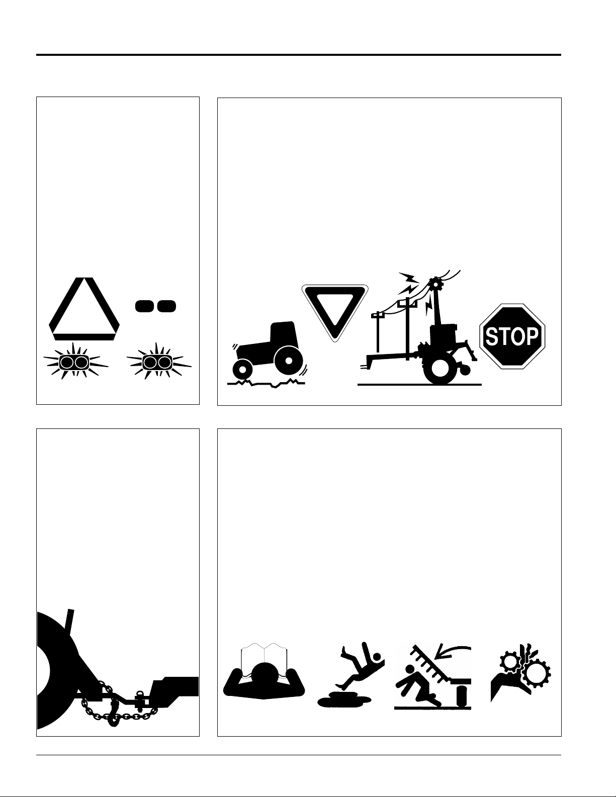
Table of Contents
Land Pride
Important Safety Information
These are common practices that may or may not be applicable to the products described in
this manual.
Use Safety
Lights and Devices
▲ Slow moving tractors, self-
propelled equipment, and towed
implements can create a hazard
when drivenon public roads. They
are difficult to see, especially at
night.
▲ Flashing warning lights and turn
signals are recommended
whenever driving on public roads.
Use lights and devices provided
with implement.
Transport
Machinery Safely
▲ Comply with state and local laws.
▲ Maximum transport speed for
implement is 20 mph. DO NOT
EXCEED.Never travel at a speed
which does not allow adequate
control of steering and stopping.
Some rough terrain require a
slower speed.
▲ Sudden braking can cause a
towed load to swerve and upset.
Reduce speed if towed load is not
equipped with brakes.
▲ Use the following maximum
speed - tow load weight ratios as
a guideline:
20 mph when weight is less
than or equal to the weight of
tractor.
10 mph when weight is double
the weight of tractor.
IMPORTANT: Do not tow a load that
is more than double the weight of
tractor.
Use A Safety Chain
▲ A safety chain will help control
drawn machinery should it
separate from the tractor
drawbar.
▲ Use a chain with the strength
rating equal to or greater than
the gross weight of the towed
machinery.
▲ Attach the chain to the tractor
drawbar support or other
specified anchor location. Allow
only enough slack in the chain to
permit turning.
▲ Do not use safety chain for
towing.
Practice Safe Maintenance
▲ Understand procedure before
doing work. Use proper tools and
equipment, refer to Operator’s
Manual for additional information.
▲ Work in a clean dry area.
▲ Lower the implement to the
ground, put tractor in park, turn off
engine, and remove key before
performing maintenance.
▲ Allow implement to cool
completely.
▲ Do not grease or oil implement
while it is in operation.
▲ Inspect all parts. Make sure parts
are in good condition & installed
properly.
▲ Remove build-up of grease, oil or
debris.
▲ Remove all tools and unused
parts from implement before
operation.
RCR2596, RCR2510 and RCRM2510 Rotary Cutters 312-753M
2
5/09/08
Page 5

Land Pride
Table of Contents
Important Safety Information
These are common practices that may or may not be applicable to the products described in
this manual.
Prepare for Emergencies
▲ Be prepared if a fire starts.
▲ Keep a first aid kit and fire
extinguisher handy.
▲ Keep emergency numbers for
doctor, ambulance, hospital and
fire department near phone.
911
Wear
Protective Equipment
▲ Protectiveclothing andequipment
should be worn.
▲ Wear clothing and equipment
appropriate for the job. Avoid
loose fitting clothing.
▲ Prolonged exposure to loud noise
can cause hearing impairment or
hearing loss. Wear suitable
hearing protection such as
earmuffs or earplugs.
▲ Operating equipment safely
requires the full attention of the
operator. Avoid wearing radio
headphones while operating
machinery.
Avoid High
Pressure Fluids Hazard
▲ Escaping fluid under pressure can
penetratethe skincausing serious
injury.
▲ Avoid the hazard by relieving
pressure before disconnecting
hydraulic lines or performing work
on the system.
▲ Make sure all hydraulic fluid
connections are tight and all
hydraulic hoses and lines are in
good condition before applying
pressure to the system.
▲ Use a piece of paper or
cardboard, NOTBODYPARTS, to
check for suspected leaks.
▲ Wear protective gloves and safety
glasses or goggles when working
with hydraulic systems.
▲ If an accident occurs, see a
doctor immediately. Any fluid
injected into the skin must be
treated within a few hours or
gangrene may result.
Keep Riders
Off Machinery
▲ Riders obstruct the operator’s
view, they could be struck by
foreign objects or thrown from the
machine.
▲ Never allow children to operate
equipment.
5/09/08
RCR2596, RCR2510 and RCRM2510 Rotary Cutters 312-753M
3
Page 6
Important Safety Information
Table of Contents
Land Pride
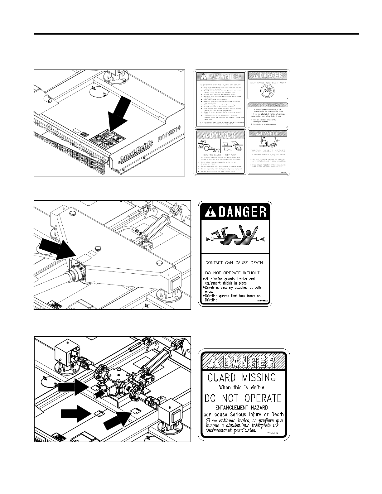
Safety Labels
YourCutter comes equipped with allsafety labels in place. They
were designed to help you safely operate your implement.
1. Read and follow label directions.
2. Keep all safety labels clean and legible.
3. Replace all damaged or missing labels.
4. Some new equipment installed during repair require safety
labels to be affixed to the replaced component as specified
by Land Pride. When ordering new components make sure
22288
the correct safety labels are included in the request. To
order new labels go to your Land Pride dealer.
5. Refer to this section for proper label placement.
To install new labels:
a. Clean the area the label is to be placed.
b. Spray soapy water on the surface where the label is to
be placed.
c. Peel backing from label. Press firmly onto the surface.
d. Squeeze out air bubbles with the edge of a credit card.
838-062C
Amber Reflector
RCR2596, RCR2510 and RCRM2510 Rotary Cutters 312-753M
4
22288
22288
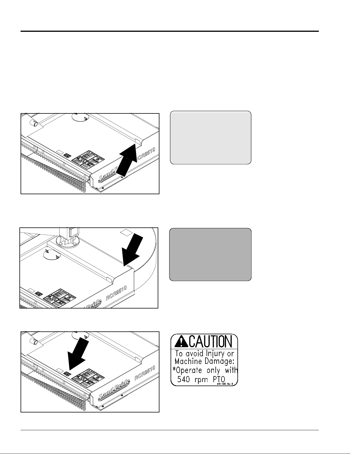
818-335C
Red Reflector
818-130C (Shown)
Caution 540 RPM
818-240C
Caution 1000 RPM
5/09/08
Page 7
Land Pride
Important Safety Information
Table of Contents
818-830C
Safety Combo
22288
22288
22297
ROTATING DRIVELINE
KEEP AWAY!
818-552C
Danger PTO Driveline
818-543C
Danger Guard Missing
5/09/08
RCR2596, RCR2510 and RCRM2510 Rotary Cutters 312-753M
5
Page 8
Important Safety Information
Table of Contents
22288
Land Pride
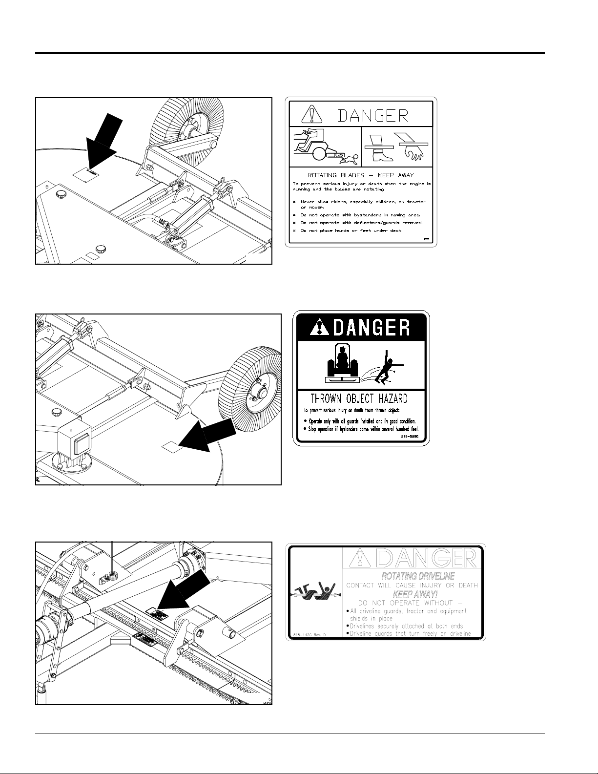
818-564C
Chain Shield
22288
22288
818-556C
Danger Thrown Object
818-142C
Rotating Driveline
RCR2596, RCR2510 and RCRM2510 Rotary Cutters 312-753M
6
5/09/08
Page 9
Land Pride
Important Safety Information
Table of Contents
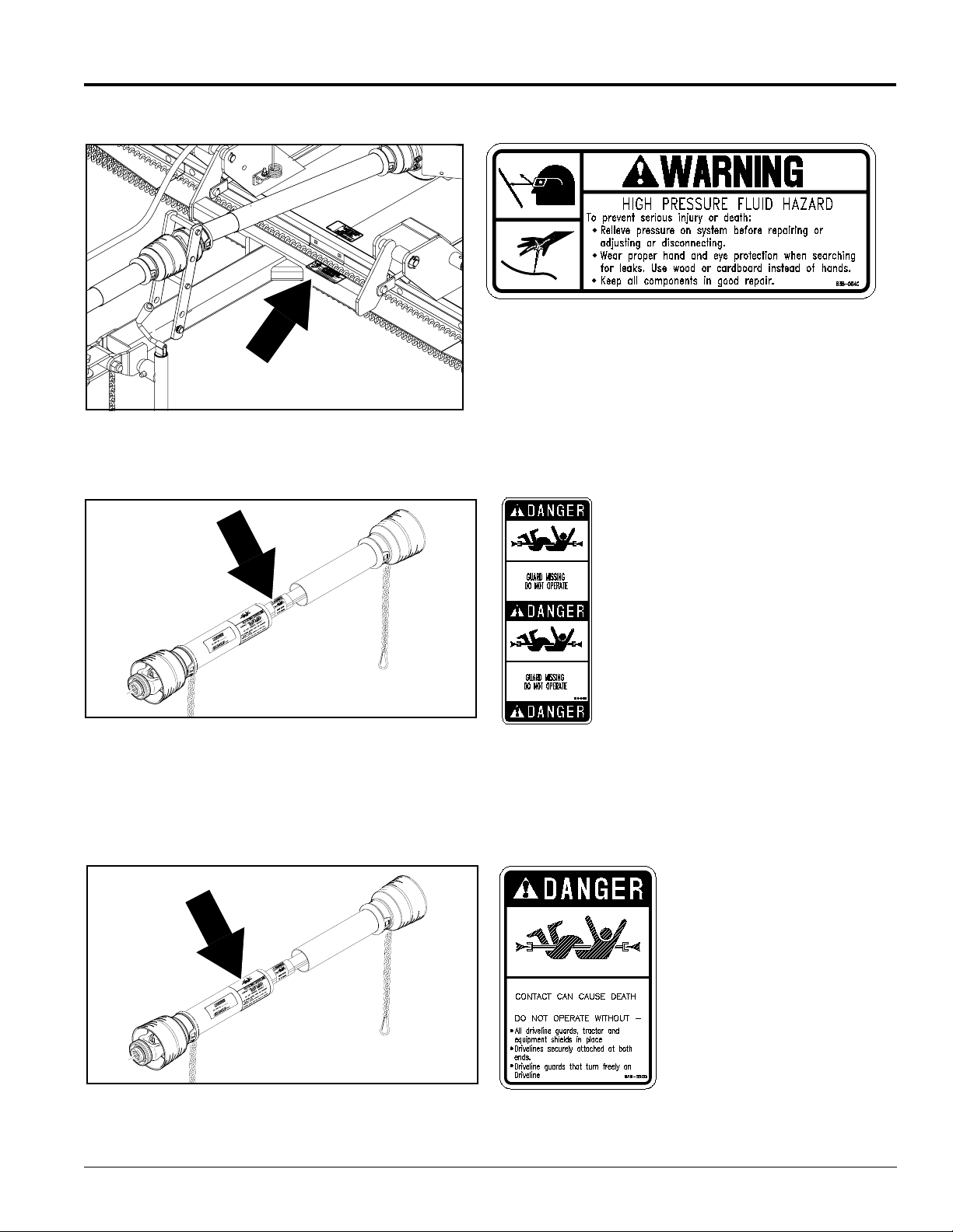
838-094C
Warning: High Pressure
22288
22296
22296
818-540C
Danger Guard Missing
Do Not Operate
ROTATING DRIVELINE
KEEP AWAY!
818-552C
Rotating Dr iveline
Hazard Keep Away
5/09/08
RCR2596, RCR2510 and RCRM2510 Rotary Cutters 312-753M
7
Page 10
Introduction
Introduction
Table of Contents
Land Pride
Land Pr ide welcomes you to the growing family of new
product owners.
This Cutter has been designed with care and built by
skilledwor kers using qualitymaterials.Proper assembly,
maintenance, and safe operating practices will help you
get years of satisfactory use from the machine.
Application
The standard utility duty RCR2596, RCR2510 and
RCRM2510Series Rotary Cuttersaredesigned andbuilt
by Land Pride to provide excellent cutting performance
on gently sloping or slightly contoured r ight-of ways,
pastures, set-aside-acres, and row crop fields. Their
eight and ten foot cutting widths, 2" to 12" cutting height
and ability to cut weeds and brush up to 1” diameter
make them well suited for these applications.
The RCR2596 and RCR2510 cutters operate at a PTO
speed of 540 rpm and the RCRM2510 cutter operates at
1000 rpm. A category four equal angle driveline is
available on all three models and a category four
constant velocity driveline is available on only the
RCR2510 & RCRM2510 models.
Pull-type and three-point type hitches are available.The
RCR2596 is designed for a categor y I or II three-point
hitchand theRCR2510 andRCRM2510are designedfor
a category II or III three-point hitch. All three-point
hitches are Quick-Hitch adaptable. The RCR2596 threepoint hitch requires a 45-110 hp tractor and the Pull-type
hitch requires a 30-110 hp tractor. The RCR2510 and
RCRM2510 three-point hitch requires a 50-110 hp
tractor and 35-110 hp for Pull-type.
Stump jumpers, main driveline slip-clutches, and
outboard flex couplers are also offered for driveline and
gearbox protection. Safety shields around the cutter are
offered in either chain or rubber.
See “Features and Benefits” section and “Product
Specifications” for more information and performance
enhancing options.
Terminology
“Right” or “Left” as used in this manual is determined by
facingthe direction the machine will operate while in use
unless otherwise stated.
Definitions
NOTE: A special point of information that the
operator must be aware of before continuing.
IMPORTANT: A special point of information related
to its preceding topic. Land Pride’s intention is that
this information should be read and noted before
continuing.
Owner Assistance
The Warranty Registration card should be filled out by
the dealer at the time of purchase. This information is
necessary to provide you with quality customer ser vice.
If customer service or repair parts are required contact a
LandPr ide dealer.A dealer hastrainedpersonnel, repair
parts and equipment needed to ser vice the Cutter.
The parts on your Cutter have been specially designed
and should only be replaced with genuine Land Pride
parts. Therefore,should yourCutter require replacement
parts go to your Land Pride Dealer.
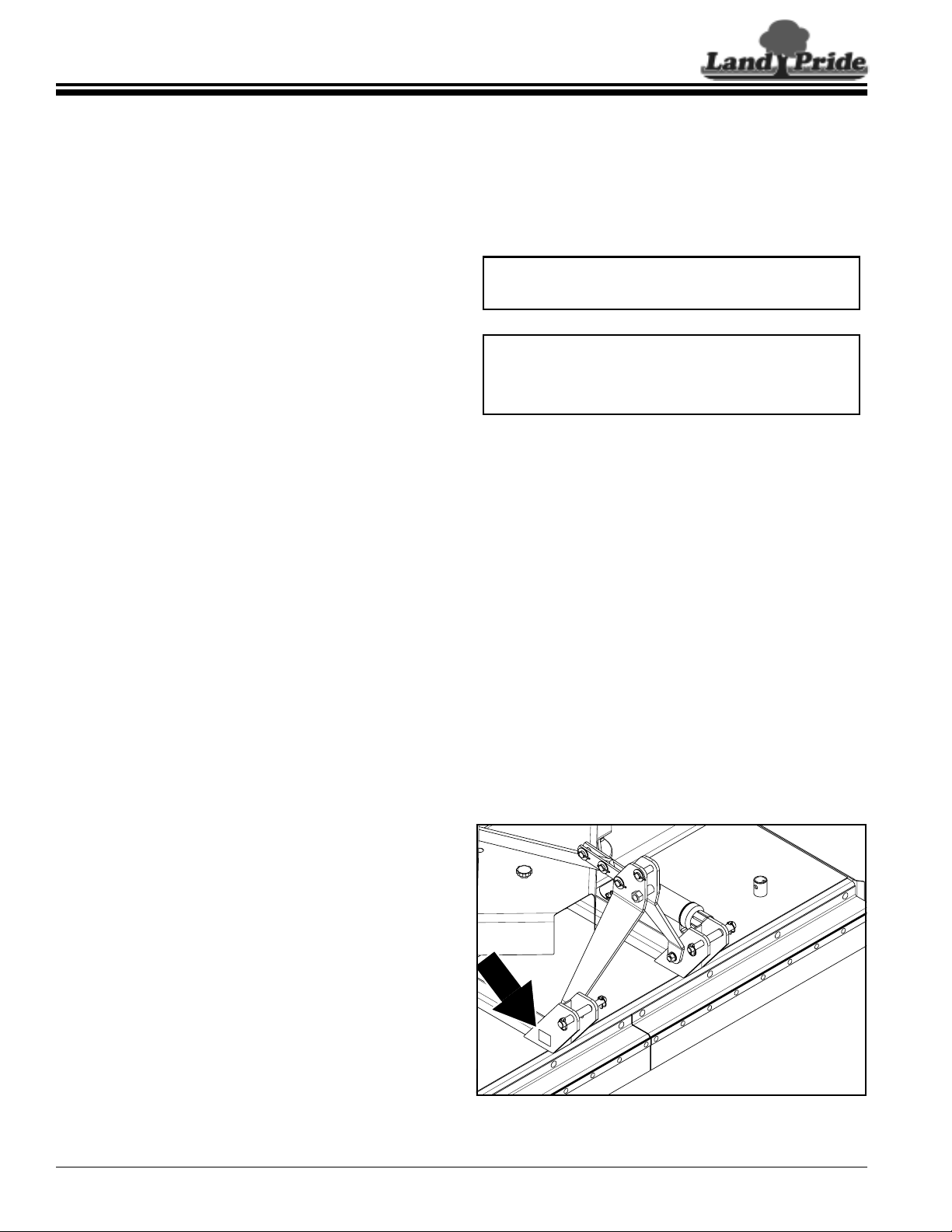
Serial Number Plate
Refer to Figure 1:
For prompt service always use the serial number and
modelnumber when ordering parts from yourLand Pride
dealer.Besure to includeyour serial andmodel numbers
incorrespondencealso. Referto Figure 1 forthe location
of your serial number plate.
Using This Manual
• This Operator’s Manual is designed to help familiarize
you with safety, assembly, operation, adjustments,
troubleshooting, and maintenance. Read this manual
and follow the recommendations to help ensure safe
and efficient operation.
• The information contained within this manual was
current at the time of printing. Some parts may change
slightly to assure you of the best performance.
• To order a new Operator’sor Parts Manual contact your
authorized dealer. Manuals can also be downloaded,
free-of-charge from our website at www.landpride.com
orprinted fromtheLand PrideService & SupportCenter
by your dealer.
RCR2596, RCR2510 and RCRM2510 Rotary Cutters 312-753M
8
16000
Serial Number Plate Location
Figure 1
5/09/08
Page 11

Land Pride
Table of Contents
Introduction
Further Assistance
Your dealer wants you to be satisfied with your new
Cutter. If for any reason you do not understand any part
of this manual or are not satisfied with the service
received, the following actions are suggested:
1. Discuss the matter with your dealership ser vice
manager making sure he is aware of any problems
youmay have and that he has had the opportunity to
assist you.
2. If you are still not satisfied, seek out the owner or
general manager of the dealership, explain the
problem and request assistance.
3. For further assistance write to:
Land Pride
Service Department
P.O. Box 5060
Salina, KS 67402-5060
5/09/08
RCR2596, RCR2510 and RCRM2510 Rotary Cutters 312-753M
9
Page 12
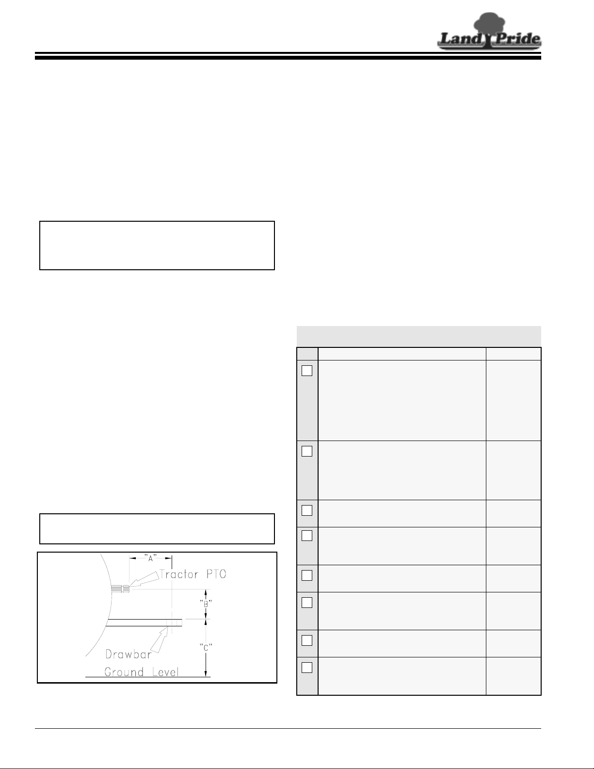
Table of Contents
Section 1: Assembly and Set-Up
Section 1: Assembly and Set-Up
Tractor Requirements
Weight & Horsepower
Tractor horsepower and weight must be capable of
controlling the cutter under all operating conditions.
Tractors outside the horsepowerrange must not be used.
• RCR2596 cutters
Three-point . . . . . . . . 45-110 HP
Pull-type. . . . . . . . . . 30-110 HP
• RCR2510 & RCRM2510 cutters
Three-point . . . . . . . . 50-110 HP
Pull-type. . . . . . . . . . 35-110 HP
NOTE: Ballast may need to be added toyourtractor
to maintain steering control. Refer to your tractor’s
operator manual to determine if one needs
additional ballast.
PTO Type & Speed
Tractor’srearpower take-off(PTO)speedand splinetype
must be capable of matching the cutter’s PTO type and
speed.
• RCR2596 and RCR2510 cutters
540 RPM 1 3/8”-6 spline rear power take-off
• RCRM2510 cutters
1000 RPM 1 3/8”-21 spline rear power take-off
Pull-Type Hitch
Refer to Figure 1-1
Distances between center of drawbar hitch pin hole to
end of tractor PTO shaft (“A” dimension) and from top of
drawbar hitch to center of PTO shaft (“B” dimension)
must be maintained when using the Pull-type hitches.
• “A” = 14" for 540 rpm
• “A” = 16" for 1000 rpm
• “B” = 8” for 540 and 1000 rpm
IMPORTANT: PTO damage may occur if distances
“A” and “B” are not properly maintained.
Land Pride
3-Point Hitch
The lower 3-Point arms of the 3-Point hitch must be
stabilized to prevent side-to-side movement. Most
tractors have sway blocks or adjustable chains for this
purpose. Category of hitch is dependent upon the series
of cutter being used.
• RCR2596 (Category l or ll hitch)
• RCR2510 & RCRM2510 (Category ll or lll hitch) Dealer Preparations
Read and understand the operator’s manual for your
cutter. An understanding of how it wor ks will aid in the
assembly and setup of your cutter.
This Rotary Cutter has been par tially assembled at the
factory. However, some assembly will be necessary to
attach the hitch, driveline and guards to the cutter.
It is best to go through the Pre-Assembly Checklist
before assembling the cutter. Speed up your assembly
task and make the job safer by having all the needed
parts and equipment readily at hand.
Pre-Assembly Checklist
Check Reference
Fasteners and pins that were shipped
with the cutter. NOTE: All hardware from
the factory has been installed in the
location where it will be used. If a part or
fastener is temporarily removed for
assembly reasons, remember where it
goes.Keep the parts separated.
Be sure the parts get used in the correct
location. By double checking while you
assemble, you will lessen the chance of
using a bolt incorrectly that may be
needed later.
All grease fittings are in place and
lubricated.
Safety labels are correctly located and
legible. Replace if damaged.
Operator’s
Manual
Operator’s
Manual
Section 5
Page 32
Safety
Information
pg. 1
PTO to Drawbar Distances
Figure 1-1
RCR2596, RCR2510 and RCRM2510 Rotary Cutters 312-753M
10
22273
Inflate tires to specified PSI air pressure.
Tighten wheel bolts to specified torque.
Red and amber reflectors are correctly
located and visible when the cutter is in
the transport position.
Have a minimum of 2 people at hand
while assembling the cutter.
Have a fork lift or loader along with
chains and safety stands that are sized
for the job ready for the assembly task.
Section 8
Page 38
Safety
Information
Page 1
Operator’s
Manual
Operator’s
Manual
5/09/08
Page 13
Land Pride
Section 1: Assembly and Set-Up
Table of Contents
Gearbox Vent Plug
Refer to Figure 1-2
Gearbox vent plugs are shipped loose and packaged
with the Operator’s Manual. Remove existing splitter
gearbox pipe plug and replace with 3/8” vent plug.
Remove wing box pipe plugs and replace with 1/2” vent
plugs.
1/2” Wing Box Pipe Plug
3/8” Splitter Box Pipe Plug
1/2” Wing Box
Pipe Plug
22320
Figure 1-2
Lift-Type Cutter
Hitch Assembly
NOTE: Do not tighten hardware until assembly is
complete. Refer to “Torque Values Chart for
Common Bolt Sizes” on page 38.
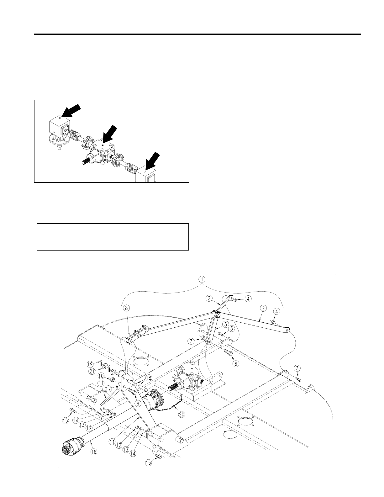
Refer to Figure 1-3:
1. Assemble the A-Frame hitch (#11) to the lower bolt
holes of the front inside hitch ears as shown. Insert
the 5/8" long bushings (#14) into the bottom holes of
theA-Framehitch. Securethe A-Framehitchwith the
3/4" bolts (#15), 3/4" flat washer (#13) and 3/4" lock
nut (#12).
2. Place the 2" long bushing (#17) between the AFramehitch as shown and insert 1” bolt (#9) through
the hole in the hitch and bushing. Secure with the 1”
lock nut (#10).
3. Assemble the two short braces (#8) that are on the
rear brace (#1) between the back holes of the
A-Frame (#11) using the clevis pin (#18) provided
and secure with the flat washer (#21) and cotter pin
(#19).
4. Assemble the two longer straight braces (#5) to the
front hole of the lug that is welded behind the
gearboxmount. Secure with the 1" bolt (#6) and lock
nut (#7).
5. Assemblethe formedrear braces(#2) tothe inside of
the inner most lugs at the rear of the cutter. Secure
with the 3/4” bolt (#3) and lock nut (#4).
6. Install the other clevis pin (#18), flat washer (#21)
and cotter pin (#19) into the top front hole of the AFrame.
Driveline Installation
1. Attachtheslip-clutch end of the driveline (#16)to the
gearbox input shaft securely. Make certain that the
slip-clutch is fully onto the input shaft splines.
Tighten the conical dog pin on back side of slipclutch to 45-50 ft-lb torque.
2. Securechain #20 toholein driveline guard.Dr iveline
guard not shown.
22289
5/09/08
Lift Type Cutter 3-Point Assembly
Figure 1-3
RCR2596, RCR2510 and RCRM2510 Rotary Cutters 312-753M
11
Page 14

Section 1: Assembly and Set-Up
Table of Contents
Land Pride
Pull-Type Cutter
Hitch Assembly
NOTE: Do not tighten hardware until assembly is
complete. Refer to “Torque Values Chart for
Common Bolt Sizes” on page 38.
Refer to Figure 1-4 for RCR2596 hitch assembly and
Figure 1-5 for RCR2510 hitch assembly:
1. Assemble tongue (#1) to the deck using hitch pins
(#2), spacer tubes (#3) and linch pins (#4).
2. Attachlevel rodassemblies (#8) to tongue(#1) using
clevis pins (#5), flat washers (#6) and cotter pins
(#7).Make sure levelrodadjusting nuts are threaded
the same distance on both rods. This will ensure a
level unit.
3. Remove hydraulic hose holder (#9) from the hitch
and install to the cutter deck with 3/4” x 1 1/2” GR5
hexhead cap screw (#12) and 3/4” hexlocknut(#13)
as shown. Tighten mounting bracket hardware as
needed to secure hose holder in place.
4. Route hydraulic hose through the hose holder loop.
5. Remove parking jack (#10) from its storage position
on the deck and attach to the tongue (#1). Secure
with attachedpin(#11). Adjust jack to desired height.
22302
RCR2596 Hitch Assembly
Figure 1-4
RCR2596, RCR2510 and RCRM2510 Rotary Cutters 312-753M
12
22290
RCR2510 Hitch Assembly
Figure 1-5
5/09/08
Page 15

Land Pride
Section 1: Assembly and Set-Up
Table of Contents
Equal Angle Driveline Installation
Refer to Figure 1-6:
Equal angle drivelines can be installed on RCR2596,
RCR2510 and RCRM2510. Maximum turning angle is
limited to 35 degrees.
1. Remove gearbox cover (cover not shown).
2. Securely attach the slip-clutch end of the driveline
jackshaft (#2) to the gearbox input shaft (#1). Make
certain the slip-clutch is fully on the gearbox input
shaft. Tighten the conical dog pin on the connection
to 45-50 ft-lbs. of torque.
IMPORTANT: Make sure the bearing (#3) inbearing
support has its locking collar facing the cutter
gearbox (#1).
3. Insert driveline jackshaft (#2) through the bearing
support assembly (#3). Pull the bearing suppor t
assembly fully against the jackshaft to extend the
jackshaft splines through the bearing and out the
other side as far as possible.
4. Install main driveline (#4) to jackshaft (#2) by pulling
onthe collar and pushingthe yokeforwardto engage
the groove on the jackshaft splined stub until the
collar has locked in place. Make certain the locking
collar has engaged by pulling on the main driveline.
5. Tighten the set screw in the bearing locking
collar (#3).
6. Replace gearbox cover.
7. Secure chain (#5) on the main dr iveline (#4) to the
bearingsupport assembly(#3). Securechain (#6) on
the jackshaftdriveline (#2) to the hole ontheleft side
of the gearbox cover (cover not shown). Secur ing
chains will restrict driveline outer shields from
rotating.
5/09/08
RCR2596, RCR2510 & RCRM2510
Equal Angle Driveline Assembly
Figure 1-6
RCR2596, RCR2510 and RCRM2510 Rotary Cutters 312-753M
22303
13
Page 16

Section 1: Assembly and Set-Up
Table of Contents
Land Pride
Constant Velocity Driveline Installation
NOTE: Do not tighten hardware until assembly is
complete. Refer to “Torque Values Chart for
Common Bolt Sizes” on page 38.
Refer to Figure 1-7:
Constant velocitydriveline can be installed on RCR2510
and RCRM2510 cutters only. Maximum turning angle is
limited to 80 degrees.
1. Securely attach slip-clutch end of jackshaft driveline
(#1) to gearbox input shaft (#8). Make certain the
slip-clutch isfullyonthe gearbox input shaft. Tighten
the conical dog pin on the connection to 45-50 ft-lb
torque.
2. Insert jackshaft driveline (#1) into pillow block
bearing (#9). Secure bearing support (#2) with 1/2”13 x 3 1/2” long bolts (#3) and 1/2” flange nuts (#4).
3. Install main driveline (#5) to jackshaft driveline (#1)
by attaching the (red) slide collar on the jackshaft.
Twist the quick disconnect on the yoke and push it
forward to engage the groove on the jackshaft
splined stub.
4. Secure chain (#7) to the tongue (#10) to restrict
driveline outer shield from rotating. Secure jackshaft
driveline chain (#6) to the hole in the left side of the
gearbox cover (cover not shown). Securing chains
will restr ict driveline outer shields from rotating.
5. Tighten nuts (#4) to proper torque.
Constant Velocity Driveline Assembly
RCR2596, RCR2510 and RCRM2510 Rotary Cutters 312-753M
14
22304
RCR2510 & RCRM2510
Figure 1-7
5/09/08
Page 17

Land Pride
Table of Contents
Section 1: Assembly and Set-Up
Chain Safety Shields (Optional)
!
DANGER!
Rotary Cutters have the ability to discharge objects at high
speeds; therefore, the use of front and rear safety shields is
strongly recommended when cutting along highways or in an
area where people may be present.
NOTE: Do not tighten hardware until assemblies
are complete. Refer to “Torque Values Chart for
Common Bolt Sizes” on page 38.
Front Chain Shields (RCR2596)
Refer to Figure 1-8
Install each front chain shield (#1) with 1/2-13 x 2 3/4”
long carr iage bolts (#2) and flange nuts (#3) as shown.
22292
RCR2596 Front Chain Shield
Figure 1-8
Front Chain Shields (RCR(M)2510)
Refer to Figure 1-9
Install front chain shields (#1) & (#2) with 1/2” -13 x 3 1/
2” longcarriage bolts (#3) andflangenuts (#4) as shown.
Rear Chain Shield
Refer to Figure 1-10
Install rear chain shield (#1) with 1/2” -13 x 1 1/2” long
carriage bolts (#2) and 1/2” flange nuts (#3) as shown.
22291
RCR2510 & RCRM2510 Front Chain Shield
Figure 1-9
5/09/08
16258
Rear Chain Shield
Figure 1-10
RCR2596, RCR2510 and RCRM2510 Rotary Cutters 312-753M
15
Page 18

Table of Contents
Section 1: Assembly and Set-Up
Rubber Safety Shields (Optional)
!
DANGER!
Rotary Cutters have the ability to discharge objects at high
speeds; therefore, the use of front and rear safety shields is
strongly recommended when cutting along highways or in an
area where people may be present.
NOTE: Do not tighten hardware until assemblies
are complete. Refer to “Torque Values Chart for
Common Bolt Sizes” on page 38.
Front Rubber Shields (RCR2596)
Refer to Figure 1-11
Install front rubber shields (#1) with 1/2” -13 x 2 3/4” long
carriage bolts (#2) and flange nuts (#3) as shown.
Land Pride
22307
RCR2596 Front Rubber Shields
Figure 1-11
Front Rubber Shields (RCR(M)2510
Refer to Figure 1-12
Install front rubber shields (#1) & (#2) with 1/2” -13 x 3 1/
2” longcarriage bolts (#3) andflangenuts (#4) as shown.
Rear Rubber Shield
Refer to Figure 1-13
Install rear rubber shield (#1) and rear shield strap (#2)
with 1/2” -13 x 1 1/2” long carriage bolts (#3) and
1/2” flange nuts (#4) as shown.
22308
RCR2510 & RCRM2510 Front Rubber Shields
Figure 1-12
RCR2596, RCR2510 and RCRM2510 Rotary Cutters 312-753M
16
16266
Rear Rubber Shield
Figure 1-13
5/09/08
Page 19

Land Pride
Section 1: Assembly and Set-Up
Table of Contents
3-Point Tractor Hook-Up
Refer to Figure 1-14:
!
DANGER!
Tractor hook-up can be hazardous to you or your helper. Do not
allow anyone to stand between the cutter and tractor during
hook-up operations. Do not operate hydraulic 3-point lift
controls while someone is directly behind the tractor.
!
CAUTION!
Always engage parking brake, shut off tractor and remove key
before dismounting from tractor.
1. Locate the cutter on a flat level surface.
2. Determine the hitch category of the tractor that will
be used:
a. Category I tractors will have a lower hitch link
hole diameter of 7/8”. The top link hole diameter
(cutter end) will be 3/4".
b. Category II tractors will have a lower hitch link
holediameterof 11/8”. Thetop linkhole diameter
(cutter end) will be 1".
c. Category III tractors will have a lower hitch link
hole diameter of 1 7/16”. The top link hole
diameter (cutter end) will be 1 5/16".
3. Removelowerlinch pins(#3) andhitch pins(#1) from
the deck. Removeupper cotter pin (#6), washer (#7)
and hitch pin (#5) from the deck.
4. Slowly back the tractor up the cutter while using the
tractor’s3-point hydraulic control to adjust the lower
linkarms upordown to match thetractor’s lowerarm
pin holes to the cutter hitch pin holes. The lower lift
arms of a Category 2 tractor will be positioned to the
outside of the cutters lower hitch lugs on the
RCR2596 & RCRM2596 cutters.
5. Re-insert hitch pins (#1) and secure with the linch
pins (#3).
6. Connect the top center link (#4) to the upper pivot
hitch using 1” clevis pin (#5), washer (#6) and cotter
pin (#7). Bend cotter pin after inserting to prevent it
from falling out.
7. Thelift link rodson yourtractor’s3- pointhitch should
be adjusted to allow for lateral float. Please consult
you tractor’s manual for adjusting instructions.
Driveline Hook-up
An additional driveline may be required if the Rotary
Cutter is used on more than one tractor especially if a
quick hitch is used.
!
CAUTION!
Do not use a PTO adaptor. A PTO adapter will increase the
strainon the tractor’s PTO shaft and can damage the PTO shaft
and mower driveline.
!
CAUTION!
Do not over speed PTO. The cutter can be damage when
operated above its rated PTO RPM.
5/09/08
3-Point Lift Type Cutter Tractor Hook-Up
Figure 1-14
RCR2596, RCR2510 and RCRM2510 Rotary Cutters 312-753M
22293
17
Page 20

Table of Contents
Section 1: Assembly and Set-Up
!
WARNING!
Damaged drivelines can cause serious injury or death.
Either a tractor with 540 rpm or 1000 rpm PTO (Power
Take-Off) speed is required. The RCR cutters are
designed for a PTO speed of 540 r pm and the RCRM
cutters are designed for 1000 r pm.
IMPORTANT: Do not attempt to operate a 540 RPM
driveline cutter with a 1,000 RPM PTO tractor and
do not operate a 1000 RPM driveline cutter with a
540 RPM PTO tractor. Many tractors provide both
540 and 1,000 RPM PTO speeds. Check your
tractor’s manual to determine its capabilities.
IMPORTANT: Avoid premature driveline
breakdown. A driveline that is operating must not
exceed an angle of 25 degrees up or down while
operating 3-point lift. See Figure 1-15 below.
24872
Land Pride
aligned and level with the tractor's PTO shaft.
Securely block cutter deck in this position.
2. Place tractor gear selector in park, shut tractor
engine off, set park brake and remove switch key.
3. Attach dr iveline to cutter and tractor as follows:
a. Slide inner yoke of driveline over the gearbox
shaft and secure with locking collar.
b. Slideouter yokeof drivelineoverthe tractor'sPTO
shaft and secure with locking collar.
c. Skip to step 5 if driveline fits between tractor and
Rotary Cutter.
Refer to Figure 1-16:
4. The driveline will require shortening if it is too long to
fit between the tractor and Rotary Cutter. Shorten
driveline as follows:
a. Check to makesure cutter and tractor PTO shafts
are level with each other and the deck is securely
supported at this height with support blocks.
b. Pull driveline profiles apart into two sections as
shown in Figure 1-16.
Maximum PTO Driveline Movement During Operation
Figure 1-15
Checking Driveline Minimum Length
IMPORTANT: Always check driveline minimum
length during initial setup, when connecting to a
differenttractor and when alternating between using
aquick hitch and astandard 3-point hitch. More than
one driveline may be required to fit all applications.
IMPORTANT: It is necessary to align and level the
tractor’s PTO shaft with the gearbox shaft when
checking driveline minimum length. Too long a
driveline can damage tractor, gearbox and driveline.
Refer to Figure 1-14 on page 17:
1. Obtain the shortest distance possible between
tractor PTO shaft and gearbox shaft by starting the
tractor and slowly engaging 3-point lift to move the
lower arms up or down until the gearbox shaft is
RCR2596, RCR2510 and RCRM2510 Rotary Cutters 312-753M
18
22311
Driveline Shortening
Figure 1-16
c. Attach outer driveline universal joint to tractor
PTO shaft and inner driveline universal joint to
gearboxshaft. Pull oneach driveline section tobe
sure universal joints are secured.
d. Hold driveline sections parallel to each other to
determine ifthey aretoo long.The inner andouter
shieldson eachsection shouldend approximately
1" short of reaching the universal joint shield on
the adjacent section (see “B” dimension). If they
are too long, measure 1" (“B” dimension) back
from theuniversal joint shield and makea mark at
this location on the inner and outer shields.
e. Cut off inner shield at mark (“X” dimension). Cut
same amount off inner shaft (“X1” dimension).
Repeat cut off procedure (“Y”&“Y1”dimensions)
to cut outer driveline half.
f. Remove all burrs and cuttings.
5/09/08
Page 21

Land Pride
Table of Contents
Section 1: Assembly and Set-Up
5. With dr iveline profiles pulled apart, apply multi-
purpose grease to the inside of the outer profile and
reassemble the two profiles.
6. Attach inner driveline yoke to the gearbox shaft and
outer dr iveline yoke to the tractor PTO shaft.
7. Thedrivelineshould now be movedback and forth to
insure thatboth ends are secured. Reattach any end
that is loose.
IMPORTANT: Two small chains are supplied with
the dr iveline. These chains must be attached to the
outer and inner driveline yoke shields and to the
cutter deck and tractor to keep the driveline shields
from rotating.
8. Hook a safetychain in the hole on the outer driveline
yoke shield and its opposite end to the tractor.
9. Hook the other safety chain in the hole on the inner
driveline yoke shield and its opposite end to the
cutter.
10. Start tractor and raise Rotary Cutter just enough to
remove support blocks fro under the cutter deck.
11. Slowly engage tractor’s 3-point controls to lower the
cutter. Check for sufficient drawbar clearance. Move
drawbar ahead, aside or remove if required.
5/09/08
RCR2596, RCR2510 and RCRM2510 Rotary Cutters 312-753M
19
Page 22

Section 1: Assembly and Set-Up
Table of Contents
Land Pride
Pull-Type Tractor Hook-Up
Refer to Figure 1-17
!
DANGER!
Crushing Hazard between tractor and implement. Do not allow
anyone to stand between the tractor and implement while
backing-up to an implement. Never operate the hydraulic
3-point lift controls while someone is directly behind the tractor.
Refer to Figure 1-17:
IMPORTANT: Jack attachment pin (#2) must be fully
inserted and secured before working on or around a
cutter that is not hooked to the tractor drawbar.
1. Make cer tain jack stand (#1) is properly attached to
the cutter hitch and secured with attachment pin
(#2).
2. Back tractor within close proximity of cutter
clevis (#6).
3. Raise or lower jack (#1) to align clevis (#6) with
tractor drawbar. Drawbar should fit between lower
and upper plates of clevis.
4. Back tractor up to cutter hitch until holes in the
drawbar and clevis (#6) are aligned.
5. Insert 1" flat washers (#5) above and below tractor
drawbar.
6. Insert 1” -8 x 4 1/2” gr5 hex bolt (3) through top of
clevis (#6), 1" washer (#5), drawbar, remaining 1"
washers (#5) and out through bottom of clevis (#6).
Secure hexbolt with locknut (#4). Tighten nut snugly
to remove all play and then back nut one-quarter
turn.
NOTE: May need to adjust the leveling rod nut
couplers to obtain correct drawbar height.
7. Attach dr iveline yoke end (#8) to tractor PTO shaft.
Secure with locking device. Pull on both end of the
driveline to make sure it is secured to the tractor and
gearbox shafts.
8. Attach hydraulic hose (#9) to tractor hydraulic outlet.
9. Fully retract the jack stand (#1), remove locking pin
(#2) and store parking jack on the cutter deck with
locking pin as shown.
Safety Chains
Refer to Figure 1-17:
When towing implements on the highway, use a safety
chain (#7) with tensile strength equal to or greater than
the gross weight of the implement to be towed by the
tractor. This will control the implement in the event the
hitch pin is lost.
Attaching safety chain (#7) to the tractor. Lock chain
hook securely to the safety chain. Make a trial r un by
driving the tractor to the right and to the left for a short
distance to check the safety chain adjustment. If
necessary, re-adjust to eliminate a tight or loose chain.
Pull-Type Tractor Un-Hook
Refer to Figure 1-17
1. Parkcutteron alevelsolid hardsurface.Place tractor
gear selector in park and set park brake.
NOTE: Always place jack stand on firm surface or
place board under jack stand for support.
RCR2596, RCR2510 and RCRM2510 Rotary Cutters 312-753M
20
RCR2510is shown.Jack islocated
onthedeck inthetransportposition
on the RCR2596.
Pull-Type Tractor Hook-Up
Figure 1-17
5/09/08
Page 23

Land Pride
Section 1: Assembly and Set-Up
Table of Contents
2. Remove parking jack (#1) from cutter deck and
secure to cutter tongue by fully inserting locking pin
(#2) through the parking jack and mounting bracket
as shown.
3. Add stroke control spacers to the cylinder rod to
preventthe cylinder from retracting. See “Pull-Type
Cutter” on page 23.
4. Use par king jack (#1) to raise and lower cutter
tongueto thecorrect heighttodisconnect clevishitch
(#6) from the tractor drawbar.
5. Remove1”-8 x 4 1/2” hex bolt (#3), flat washers (#5)
and locknut (#4) from the clevis hitch (#6).
6. Disconnect hydraulic hose (#9) from tractor. Store
hose end on cutter deck.
Check Chains, 3-Point Lift-Type Cutters
(Available through Land Pride par ts department.)
Refer to Figure 1-18:
Check chains are used to control the cutting height and
allowthe mower to belowered to the samepresetcutting
height effor tlessly.
1. Installlower endof checkchain(#1) totheinner hitch
ear as shown in Figure 1-18, using the 3/4”-10 x 1 1/
2 long bolts (#2), lock washers (#3) and nuts (#4).
Tighten securely.
2. Install chain lugs (#5) on either side of the tractor top
link mount using pin (not supplied).
3. Cuttingheightis then set byplacing proper chain link
in key slot (#5).
NOTE: For additional safety in transport, raise
cutterashigh as possible, and shortencheck chains
to prevent inadvertent falling in transport.
22314
5/09/08
Check Chain Assembly
Figure 1-18
RCR2596, RCR2510 and RCRM2510 Rotary Cutters 312-753M
21
Page 24

Table of Contents
Section 2: Adjustments
Section 2: Adjustments
Leveling Procedure
Lift-type and Pull-Type cutters must operate level from
side to side at all times. Gauge wheels should be set at
identical heights.
Lift-Type Cutter
There are fourpr imary adjustments that should be made
prior to actual field operations:
a. Deck level from left to right
b. Tractor top link length
c. Tractor lower link height
d. Tailwheel height
Proper adjustment of each of these items will provide for
higher efficiency, improved cutting performance and
longer blade life. The following tools will be needed:
a. Pliable tape measure
b. Spirit or carpenter’s level
c. Open end or hex end wrench or socket set
d. Protective gloves
Refer to Figure 2-1:
1. Having completed the “Tractor Hook-up”, locate
the tractor on a flat, level surface.
2. Usethe tractor’shydraulic3-point controltolowerthe
cutter until the tailwheel contacts ground surface.
3. Placea spiritlevelor othersuitable levelingdevice on
the front of the cutter deck as shown. Adjust either
one or both of the tractors lower link height
adjustments to levelthe deck from left to right. Some
tractors have only a single adjusting crank.
4. Similarly, place a level on either of the main deck
channels. Shorten or lengthen the tractor’s top
center link to level the cutter deck from front to rear.
Land Pride
Pull-Type Cutter
There are two primary adjustments that should be made
prior to actual field operations:
a. Deck level from left to right
b. Cutting height
Proper adjustment of each of these items will provide for
higher efficiency, improved cutting performance and
longer blade life. The following tools will be needed:
a. Pliable tape measure
b. Spirit or carpenter’s level
c. Open end or hex end wrench or socket set
d. Protective gloves
Refer to Figure 2-2:
1. Havingcompleted“TractorHook-up”,locate tractor
and cutter on a flat, level surface.
2. Use tractor’s hydraulics to adjust deck height above
ground level 2 to 3 inches.
3. Place a spirit level (#3) or other suitable leveling
device on either of the main deck channels.
NOTE: The unit cuts most efficiently if the front of
the cutter is slightly lower than the back.
Lengthening leveling rods with adjusting nuts (#2)
lowers the front of the cutter.
4. If cutter deck is not slightly lower at the front than at
the back, then loosen jam nuts (#1) on both sides
and rotate leveling rod adjusting nuts (#2) until deck
is slightly lower by an equal amounts on both sides.
5. Be sure that the right and left leveling rods are
equally tight and then re-tighten jam nuts (#1).
NOTE: The unit cuts most efficiently if the front of
the cutter is slightly lower than the back.
Deck Leveling
Figure 2-1
RCR2596, RCR2510 and RCRM2510 Rotary Cutters 312-753M
22
22315
26559
Deck Leveling
Figure 2-2
5/09/08
Page 25

Land Pride
Table of Contents
Section 2: Adjustments
Cutting Height Adjustment
!
DANGER!
Engage parking brake, disengage PTO, shut off tractor and
remove key before proceeding. Ensure that all moving parts
have come to a complete stop before dismounting from the
tractor.
!
CAUTION!
Wear a pairof gloveswhen performing this operation. Go to the
backof the cutter and carefullyrotateeach bladeto the position
shown in Figure2-3. Avoid directcontact with the cutting edge
of the blade.
Refer to Figure 2-3:
Measure distance from cutting tip of the front cutting
blade to ground surface. This distance is the cutting
height.
Lift-Type Cutter
Refer to Figure 2-4:
Adjust the tailwheel if cutting height is too high or too low.
1. Use tractor’s 3-point hydraulic control to lift cutter so
that the tailwheel clears the ground.
2. Remove existing hardware; 1/2” -13 x 1 1/2" long
carriage bolt (#1) and 1/2” flange nut (#2).
3. Adjust tailwheel up or down to desired cutting height
by repositioning adjusting plate (#3) and then
replacing the hardware.
4. Tighten 1/2” flange nut (#2) to the correct torque.
Refer to “Torque Values Chart for Common Bolt
Sizes” on page 38.
22316
Cutting Height
Figure 2-3
16269
3-Point Cutter Height Adjustment
Figure 2-4
Pull-Type Cutter
Refer to Figure 2-5:
Lift mechanism for pull-type units can be equipped with
eithera ratchetjack (#1)or hydrauliccylinder (#2).Adjust
lifting mechanism if cutting height is too high or too low.
Ratchet Jack Instructions
The deck can be raised or lowered by setting the ratchet
mechanism on the ratchet jack (#1) and then pumping
the jack handle to raise or lower the cutter to desired
cutting height.
Hydraulic cylinder Instructions
Stroke control spacers (#3) are included with the
hydraulic set-up. They consist of cast steel halves with
spring clips to hold the two halves together.
1. Extend the hydrauliccylinder to free up space on the
cylinder rodforinstalling and removing spacers.Add
or remove spacers as needed.
2. Retract hydrauliccylinder and re-measure to verify if
cutting height is suitable.
3. Store stroke control spacers on hydraulic hose (#4)
near the hydraulic cylinder.
5/09/08
Pull-Type Lift Selections
Figure 2-5
RCR2596, RCR2510 and RCRM2510 Rotary Cutters 312-753M
22318
23
Page 26

Table of Contents
Section 3: Operating Procedures
Section 3: Operating Procedures
Operating Check List
It is absolutely essential that no one operates the Rotary
Cutter without first having read, fully understood and
becometotally familiarwiththe Operator’sManual. Make
sure the operator has paid particular attention to:
• Important Safety Information, pages 1 to 7
• Section 1: Assembly and Set-Up, page 10
• Section 2: Adjustments, page 22
• Section 3: Operating Procedures, page 24
• Section 4: Maintenance & Lubrication , page 28
In addition to design and configuration of equipment,
hazard control and accident prevention are dependent
upon the awareness, concer n, prudence and proper
traininginvolvedin theoperation, transport,maintenance
and storage of equipment. Before beginning to cut, the
following inspection should be performed.
Land Pride
IMPORTANT: Stop PTO immediately if vibration
continues after a fewrevolutionsduring start-up and
anytimeit occurs thereafter. Waitfor PTOto come to
a complete stop before dismounting from tractor to
check for probable causes. Make necessary repairs
and adjustments before continuing on.
7. Start tractor, set throttle to idle or slightly above idle
and slowly engage the PTO. Initial start-up vibration
is normal and should stop after a few revolutions.
StopPTO rotationimmediately if vibrationcontinues.
IMPORTANT: Do not exceed rated PTO speed of
the cutter. Excessive engine speed will cause
damage to the power train components.
8. Once the cutter is running smoothly,increase tractor
PTO speed to 540 RPM. Stop PTO rotation
immediately if vibration occurs.
Operating Checklist
Check Reference
“Important Safety Information” in
this Manual.
Check oil level in gearboxes. Section 3
Checkthat all plugs in gearboxhave
been replaced properly.
Be sure nuts and bolts are tight. Section 7
Be certain all guards and shields
are in place.
Lubricate the cutter as needed.
Refer to “Maintenance and
Lubrication”.
Make the following inspections after hooking-up to the
cutter. See hook-up instructions beginning on page 17.
Make cer tain the PTO is disengaged and completely
stopped before continuing.
1. Inspect tractor safety equipment to make sure it is in
good working condition.
2. Carefully raise and lower implement to ensure that
thedrawbar,tires,and otherequipment onthe tractor
do not contact the cutter frame or PTO driveline.
3. Checkall hosesand wiresto be surethat theywill not
contact PTO driveline. Check PTO guards to make
certain they are in good condition and in place.
4. Inspect Hydraulic hoses for wear, damage and
hydraulic leaks.
Hazard”on page 3.
with genuine Land Pride parts.
5. With the PTO disengaged and completely stopped,
check cutting blades for sharpness.
6. (Lift-Type Cutter) Adjust tractor lower 3-point arms
such that the PTO driveline is approximately level.
See “Avoid High Pressure Fluids
Replacedamaged andwor n hoses
Page 1
Page 32
Section 3
Page 32
Section 1
Page 15
Section 4
Page 28
Transpor ting the Cutter
!
CAUTION!
When traveling on public roads at night or during the day, use
accessory lights and devices for adequate warning to operators
of other vehicles. Comply with all federal, state and local laws.
IMPORTANT: Always disengage the tractor’s PTO
before raising the cutter to transport position.
1. Makesure driveline does notcontact tractor or cutter
when raising cutter to the transport position.
2. Reduce tractor ground speed when turning and
leave enough clearance so cutter does not contact
obstacles such as buildings, trees or fences.
3. Limit transport speed to 20 mph. Transport only with
a farm tractor of sufficient size and horse power.
4. Whentraveling onroadways, transport in sucha way
that faster moving vehicles may pass you safely.
5. Shift tractor to a lower gear when traveling over
rough or hilly terrain.
Un-hooking the Cutter
Thefollowingstepsshould be donewhen un-hooking the
cutter from the tractor.
1. Park on a level solid surface.
2. Shut tractor engine off and engage parking brake.
• Lift-Type:Lowerdecktolevelground oronto blocks
supporting deck just above ground level.
• Pull-Type: See Pull-Type Tractor Un-Hook on
page 20.
3. Unhitch from tractor.
4. See “Storage Instructions” on page 31 if cutter is
not going to be used for a long time.
RCR2596, RCR2510 and RCRM2510 Rotary Cutters 312-753M
24
5/09/08
Page 27

Land Pride
Section 3: Operating Procedures
Table of Contents
Cutting Instructions
!
DANGER!
The use of front & rear safety shields is strongly recommended
to prevent injury or death caused by thrown objects! Gearbox
shields must be securedin place when operating to avoid injury
or death from entanglement in rotating drivelines.
!
DANGER!
Rotary Cutters have the ability to discharge objects at high
speeds. Therefore, the use of front & rear safety guards is
strongly recommended to prevent injury or death caused by
thrown objects!
!
CAUTION!
Damage may occur if exceeding the rated cutting capacity of
the cutter!
!
CAUTION!
Do not over speed PTO or machine damage may result. The 8’
model in this series is available in 540 RPM. The 10’ model in
this series is available in 540 RPM or 1000 RPM. Know what
your tractor requirements are.
!
WARNING!
The RCR25 series cutter is designed to cut grass and brush up
to 1” in diameter. Using his cutter for any other type of work
can damage the drive components, deck and support frame.
!
DANGER!
Do not use deck as a fan. Cutting blades are not properly
designed or guarded for this use. Using the deck as a fan can
result in injury and/or death.
This cutter wasdesigned to cut grassand medium br ush
in r ight-of-ways, pastures and for shredding row crop
residues.
1. Thoroughly Inspect the area to be cut for debris and
unforeseen objects. Mark any potential hazards.
2. Start machine slowly allowing cutter blades to
become aligned properly before going to full power.
3. It is important to maintain correct RPM PTO speed.
Loss of PTO speed will allow blades to hinge back
and result in ragged, uneven cutting.
4. Never run fast enough to overload the tractor or
cutter. Ground speed depends on two things:
• The density of material being cut.
• Size of tractor operating the cutter.
5. After the first 50 feet, stop and check to see that the
cutter is adjusted properly.
6. Do not engage PTO with 3-point in the fully raised or
position.
7. Periodically disengage PTO, turn off tractor, remove
ignition key and check for foreign objects wrapped
around the rotor shaft. Block cutter deck up before
removing objects.
Turning Angles for Pull-Type Cutters
Refer to Figure 3-1 and 2-3:
Avoidtractor-to-cutter turning angles exceeding 35
degrees if the main driveline is a standard conventional
drive shaft. The turning angle may be increased to 80
degrees if equipped with a constant velocity driveline
shaft.These extremeangles are intendedfor intermittent
usage only and not prolonged usage. Plan your field
cutting to minimize the number of turns as well as
extreme angles where turns are necessary.
!
DANGER!
Do not operate and/or travel across steep inclines where a
tractor can roll-over resulting in serious injury or death.
Consult your tractor’s manual for acceptable inclines the
tractor is capable of traveling across.
!
CAUTION!
Tractor PTO shield and all Rotary Cutter guards must be in
place at all times during operation!
IMPORTANT: Avoidcatching the hydraulichoses on
brush, post, stumps, and other protrusions that
could damage and/or break them.
NOTE: Your cutter is equipped with free swinging
cutting blades to reduce shock loads to the cutter if
striking obstacles.
5/09/08
Conventional U-Joint Driveline
Figure 3-1
CV Driveline
Figure 3-2
RCR2596, RCR2510 and RCRM2510 Rotary Cutters 312-753M
11934
20795
25
Page 28

Section 3: Operating Procedures
Table of Contents
Land Pride
Crossing Steep Ditches & Banks
Refer to Figure 3-3:
!
WARNING!
Damage to the tractor’s PTO components and/or driveline
components can cause the driveline to come loose and cause
bodily injury to the operator and others.
IMPORTANT: Always cross steep ditches and
banks at a diagonal. Never cross straight across a
steep ditch or bank and never back into a steep
ditch or bank.
Cutting over ditches and backing up hills can tilt the
cutter’sbackside upexcessivelyresulting in “Bottoming
Out” the driveline. Bottoming out is when the driveline
shaft has shorten to the point it is pressing against the
gearbox and tractor PTO shafts. Once a driveline has
bottomed out, it can not be shorten anymore without
causingserious damageto the tractor PTOcomponents,
cutter gearbox and driveline.
Do not operate a pull-type cutter at an angle exceeding
25 degrees up or down or at any angle that will force the
driveline to bind and/or hit the tractor drawbar.
Right
Ditch / Bank
Ditch / Bank
Wrong
Crossing Steep Ditches and Banks
Figure 3-3
General Operating Instructions
Now that you have familiarized yourself with the
Operator’s Manual, completed the Operators Checklist,
properly attached your Cutter to your tractor, made the
right leveling adjustments, and preset your cutting
height, you’re almost ready to begin using your Land
Pride Rotary Cutter.
It’s now time to do a r unning operational safety check.
Shut the tractor off immediately and remove the key if at
any time during this safety check you detect a
malfunction in either the cutter or tractor. Make
necessary repairs or adjustments before continuing on.
If you have a three-point hitch model make sure the
tractor’s park brake is engaged, the tractor’s PTO is
disengaged,and the cutteris resting onthe ground. Start
the tractor and then back the tractor throttle off until the
engine is at low idle. With the tractor’s rear hydraulic lift
controllever,raisethecutter to transport position making
sure that the PTO shaft is not in a bind and does not
come incontactwith the cutter frame. Lower thecutter to
the ground and, with the tractor still at low idle, engage
the PTO. If everything is running smoothly at this point
increase the engine rpm until the tractor’s engine
reaches full PTO operating speed. The RCR2596 and
RCR2510 will be 540 rpm only while the RCRM2510 is
designed to operate at 1000 rpm PTO speed. Slowly
raise the cutter to transport height to make sure the
drivelinedoes not bind or chatter.Then return the engine
to low idle, disengage the PTO, and position the
adjustablestops on the tractor’shydraulic lift leverso the
cutter can be consistently returned to the same cutting
and transport height.
Ifyou havea pull-type cutter,make surethepar k brake is
on and the cutter is on the ground in mowing position.
Start the tractor and reduce engine speed to low idle.
Engage the PTO and increase engine rpm until you
reach full PTO speed. If everything is running smoothly
your running safety check is complete and you may shut
the tractor and cutter off.
You should now be ready to move to the cutting site to
begin mowing. You should have inspected and should
only be cutting in an area you are familiar with which is
freeof debrisand unseen objects.Neverassumean area
is clear and extremely tall grass should be cut twice to
detect potential hazards. In the event you do strike an
object stop the tractor and cutter immediately to inspect
the cutter and make any necessar y repairs before
resuming operation. It pays to inspect a new area and to
develop a plan before you cut.
Normal mowing speed will be between 2-5 mph and you
will need to maintain 540 rpm PTO speed to produce a
clean cut, so make a tractor gear and range selection
that will maintain this combination. Generally the quality
of cut will be better at lower ground speeds and cutting
denserground coverwillcreatethe needto slowdown. In
certain conditions tractor tires will roll grasses down
resulting in an unevencutting height when the grass fails
torebound beforebeing cut. Whenthis happens youmay
need to reverse the cutting direction and double cut to
achievethe desired finish. You will wantto avoid very low
cutting heights especially on extremely uneven terrain.
Always cut downward on slopes and avoid crossing the
face of steep slopes. Avoid sharp drops and cross
diagonally through dips to preventhanging up the tractor
and cutter.Slow down in turns and avoidsharp turns if at
all possible. Remember to look back often.
Now you’re prepared and well briefed so lets begin
cutting. Reduce the tractor’s engine rpm, make sure the
cutteris onthe groundand incutting position, engagethe
PTO,raise theengine rpm tothe appropriate PTOspeed,
andbegin mowing.Whenit is difficultto makea wide turn
and you need to reverse direction, the three point hitch
models can be lifted into transport position to make a
RCR2596, RCR2510 and RCRM2510 Rotary Cutters 312-753M
26
5/09/08
Page 29

Land Pride
Table of Contents
Section 3: Operating Procedures
tighttur n. Operatorsofpull-type modelsmust planahead
and choose a cutting pattern that allows for wider turns.
Try increasing or decreasing ground speed to deter mine
theeffect onquality of cut.With alittlepractice youwill be
pleased with what you and your Land Pride Cutter can
do.
Whenyou are done mowing,need to takeabreak, or just
need to make a fewadjustments to the cutter,remember
to always do the following: reduce the tractor’s engine
rpm, disengage the PTO, stop on level ground, set the
park brake, turn off the engine and remove the key.
See “Features and Benefits” section or “Product
Specifications” for additional information and
performance enhancing options.
5/09/08
RCR2596, RCR2510 and RCRM2510 Rotary Cutters 312-753M
27
Page 30

Table of Contents
Section 4: Maintenance & Lubrication
Section 4: Maintenance & Lubrication
Land Pride
Maintenance
Properservicing andadjustment is the keytothelong life
of any implement. With careful and systematic
inspection, you can avoid costly maintenance, time and
repair.
Afterusing yourcutterfor severalhours, checkall bolts to
be sure they are tight.
Replace any worn, damaged or illegible safety labels by
obtaining new labels from your Land Pride Dealer.
Service Cutting Blades
!
DANGER!
Always disconnect main driveline from tractor PTO before
servicing the underside of the cutter deck. Cutter can be
engaged if tractor is started resulting in damage to the cutter,
bodily injury and/or death.
!
WARNING!
Always secure cutter deck in the up position with solid supports
before servicing the underside of the cutter. Never work under
equipment supported by hydraulics. Hydraulics can drop
equipment if controls are actuated or if hydraulic lines burst.
Either situation can drop the cutter instantly even when power
to the hydraulics is shut off.
balance. The following precautions should be taken
when sharpening blades:
a. Do not remove more material than necessary.
b. Do not heat and pound out a cutting edge.
c. Do not grind blades to a razor edge. Leave a blunt
cutting edge approximately 1/16” thick.
d. Always grind cutting edge so end of bladeremains
square to cutting edge and not rounded.
e. Do not sharpen back side of blade.
f. Both blades should weigh the same after
sharpening with not more than 1 1/2 oz. difference.
Refer to Figure 4-1:
6. Make cer tain when installing cutter blades that the
bladeson onespindle ispositioned 90degrees tothe
blades on the other spindle as shown in Figure 4-1.
7. Carefully check cutting edges of blades in relation to
blade carrier rotation to ensure correct blade
placement.Blade rotation iscounterclockwise onthe
left side and clockwise on the right side as shown.
Airfoil (lift) must be oriented towards the top of the
deck.
CW
IMPORTANT: Replace cutting blades with genuine
Land Pride blades only. Blades must be replaced in
mating pairs. Not replacing both blades will result in
an out-of-balance condition that will contribute to
premature bearing break down on the spindle hub
and create structural cracks in cutter housing.
Always inspect cutting blades before each use. Make
certain theyare properly installed andare in good working
condition.Replace anyblade thatis damaged, worn,bent,
orexcessivelynicked.Smallnickscan beground outwhen
sharpening.
1. Place tractorgearselectorin park and/or set brakes,
shut engine off and remove ignition key.
2. Disconnect main driveline from tractor PTO and
secure cutter deck in the up position with solid
supports before servicing underside of cutter.
3. Inspect cutting blades. Make cer tain they are
properly installed and are in good working condition.
Replace any blade that is damaged, worn, bent, or
excessively nicked. Small nicks can be ground out
when sharpened.
4. To remove blades from the cutter, align blade bolts
with blade bolt access hole located in the deck.
5. Both blades should be sharpened at the same angle
as the original cutting edge and must be replaced or
re-ground at the same time to maintain proper
CCW
Blade Positioning and Rotational Directional
Figure 4-1
Refer to Figure 4-2:
IMPORTANT: Examine blade bolts (#1) and
washers(#5) forexcessive wearand replace if worn.
IMPORTANT: Locknuts can loose their ability to
lock properly once removed. Therefore, always use
a used blade nut or plain nut in steps 8 & 9 below
and then replace used nut with new locknut in
step 10.
8. Start by assembling blades without shim (#2). Insert
blade bolt (#1) through blade (#3), dish pan (#4) and
flatwasher (#5).Temporary secureblade witha used
1 1/8"-12 nut. Draw nut up snug. Do not tighten.
RCR2596, RCR2510 and RCRM2510 Rotary Cutters 312-753M
28
5/09/08
Page 31

Land Pride
Section 4: Maintenance & Lubrication
Table of Contents
9. Check blade deflection. If deflection is greater than
3/4", remove blade bolt and reassemble as before
except include shim (#2) in the assembly. Select
shim thickness based on deflection. The greater the
deflection, the thicker the shim.
10. Once blade deflection is correct, replace used nut
with new locknut (#6) and torque to 450 ft-lbs.
11. Ifreplacingdishpan (#4), nuton gearboxoutput shaft
should be torqued to 450 ft-lbs. minimum and cotter
pin installed in nut with legs securely bent around
nut.
3/4" maximum
blade deflection
when blade
bolts are tight
Driveline Protection
Cutter drive components are protected from shock loads
by a friction slip-clutch. The clutch must be capable of
slippage dur ing operation to protect the gearbox,
driveline and other drive train parts.
Clutch Run-In
Friction clutches should be “r un-in” prior to initial
operation and after long periods of inactivity to remove
any oxidation that may have accumulated on fr iction
surfaces. To prevent driveline and gear box damage,
repeat “run-in” instr uctions at beginning of each season
and when moisture and/or condensation seizes inner
friction plates.
!
CAUTION!
Engage parking brake, disengage PTO, shut off tractor, and
remove key before making any of the following adjustments.
Refer to Refer to Figure 4-3:
1. Using a pencil or other marker, scribe a line across the
exposed edges of the clutch plates and friction discs.
Cutter Blade Assembly
Figure 4-2
Land Pride Cutter Blade Parts
Item Part No. Part Description
318-586A BLADE BOLT KIT
(Includes items 1, 2, 5, & 6 below)
1 802-277C BLADE BOLT 1 1/8-12 x 3 7/16 WITH KEY
2 312-075D BLADE SPACER 16 GA. (.060")
2 312-082D BLADE SPACER 18 GA. (.048")
2 312-089D BLADE SPACER 20 GA. (.036")
2 312-808D BLADE SPACER 24 GA. (.024")
3 --------- SEE LIST OF CUTTER BLADES BELOW
4 312-881H 27 x 10G OVAL DISHPAN WELDMENT
5 804-147C WASHER FLAT 1 HARD ASTMF436
6 803-170C NUT HEX TOP LOCK 1 1/8-12 PLATE
Land Pride List of Cutter Blades
Part No. Part Description
820-195C RCR2596 CUTTER BLADE 1/2 x 4 x 20 CCW
820-196C RCR2596 CUTTER BLADE 1/2 x 4 x 20 CW
820-137C RCR2510 CUTTER BLADE 1/2 x 4 x 25 CCW
820-112C RCR2510 CUTTER BLADE 1/2 x 4 x 25 CW
Optional Low Lift Cutter Blades
820-210C RCR2596 BLADE 1/2X4X20.5 LL CCW
820-211C RCR2596 BLADE 1/2X4X20.5 LL CW
820-193C RCR2510 BLADE 1/2X4X25 LL CCW
820-209C RCR2510 BLADE 1/2X4X25 LL CW
13693
Clutch
Figure 4-3
2. Carefullyloosen each of the8 spring retainer nutson
the clutch housing a total of EXACTLY 2 revolutions.
Itwill be necessary tohold the hexend ofthe retainer
bolt inorderto count the exact numberofrevolutions.
3. Start tractor and engage driveline for 2-3 seconds to
permit slippage of the clutch surfaces. Disengage
the PTO, then re-engage a second time for 2-3
seconds. Disengage the PTO, shut off tractor and
remove key. Wait for all components to stop before
dismounting from tractor.
4. Inspect clutch and ensure that scribed markings
made on the clutch plates have changed position.
Slippage has not occurred if any two marks on the
friction disc and plate are still aligned.
5/09/08
RCR2596, RCR2510 and RCRM2510 Rotary Cutters 312-753M
29
Page 32

Table of Contents
Section 4: Maintenance & Lubrication
Land Pride
IMPORTANT: The clutch must be disassembled into
separate friction discs if one or more friction disc did
not slip during clutch run-in operation. See Clutch
Disassembly on page 30.
5. Tighten each spring retainer nut on the clutch
housing exactly 2 revolutions to restore clutch to
original setting pressure. See Clutch Assembly on
page 30 for exact spring length.
6. The clutch should be checkedduring the first hour of
cutting andperiodically each week.An additional set
of scribe marks can be added to check for slippage.
Clutch Disassembly
Refer to Figure 4-4:
Disassembly of the clutch is simply a matter of removing
the spring retainer nuts (#1), springs (#2) and bolts (#3)
from the assembly. Each friction disc (#4) must then be
separated from the metal surface adjacent to it.
Clutch Inspection
Inspect all parts for excessivewear and condition. Clean
all parts that do not require replacement.The original
friction disc thickness is 1/8" (3.2 mm) and should be
replaced if thickness falls below 3/64" (1.1 mm). If
clutches havebeen slipped to the point of “smoking”, the
friction discs may be damaged and should be replaced.
Heat build-up may also affect yoke joints.
Clutch Assembly
Refer to Figure 4-4:
Install new friction discs if needed and reassemble all
components in proper order. Reassemble each friction
disc (#4) next to the metal plate it was separated from.
Installbolts(#3) through the end plates andintermediate
plates as shown. Place springs (#2) over the bolts and
secure with nuts (#1).
Refer to Figure 4-5:
Progressively tighten each spring retainer bolt until
correct spr ing height “A” is reached. See Tables below
Figure 4-5.
24600
Clutch Adjustment
Figure 4-5
RCR2596
Driveline
No.
826-255C
826-256C
Driveline
Location
Main
Jack Shaft
PTO
Speed
540 4 1.175" (S/N 566919+)
Cat
No.
A (inches)
Spring Height
1.12" (S/N 566918-)
RCR(M)2510
Driveline
No.
826-215C
826-220C
826-225C
826-216C
826-221C
826-226C
Driveline
Location
Main
Jack Shaft
Stub Shaft
Main
Jack Shaft
Stub Shaft
PTO
Speed
540 4
1000 4
Cat
No.
A (inches)
Spring Height
1.175" (S/N 566919+)
1.12" (S/N 566918-)
1.09" (S/N 566919+)
1.02" (S/N 566918-)
4-Plate Slip Clutch Assembly (540 RPM Shown)
Figure 4-4
RCR2596, RCR2510 and RCRM2510 Rotary Cutters 312-753M
30
14714
5/09/08
Page 33

Land Pride
Section 4: Maintenance & Lubrication
Table of Contents
Flex Couplers
Refer to Figure 4-6:
Replace r ubber disc (#6) as follows:
1. Insert 3-bolts (#1) through the holes in flange
weldment (#7).
2. Place beaded washers over the 3-bolts with bead
facing rubber disc (#6).
3. Place bushings (#3), rubber disc (#6) and washers
(#4) over the 3-bolts as shown.
4. Secure with nuts (#5). Do not tighten.
5. Insert 3-bolts (#1) through the holes in flanged
hub (#8).
6. Repeat steps 2 through 4.
7. Tighten nuts (#5) evenly with nuts torqued 35 to
40 ft-lb. Beaded washers (#2) should be imbedded
halfway into the r ubber disc.
Land Pride Skid Shoe Replacement Parts
Part No. Part Description
312-602D SKID SHOE
802-603C PLOW 3/8-16 x 1 GR5
803-198C NUT HEX WHIZ 3/8-16 PLT
1. Remove3/8" hexwhiz nuts (#3), 3/8" plow bolts (#2)
and skid shoe (#1) as shown.
2. Plow bolts should be checkedfor wear and replaced
if necessary.
3. Attach new skid shoe (#1) to cutter with existing
3/8” plow bolts (#2) and secure with 3/8" hex whiz
nuts. Torque to 31 ft. lbs.
4. Repeat on opposite side.
Tractor Maintenance
One of the most important things you can do to prevent
hydraulicsystem problemsis toensure that yourtractor's
reservoir remains free of dirt and contamination.
Use a cleanclothtowipe the hose ends before attaching
them to your tractor. Replace the filter element for your
tractor’s hydraulic system at the prescribed intervals.
Thesesimple maintenances willgo a longwayto prevent
the occurrence of cartridge valve and hydraulic cylinder
problems on the Rotary Cutter.
22325
Flex Couplers
Figure 4-6
Skid Shoe Maintenance
Refer to Figure 4-7:
!
WARNING!
Excessive wear on skid shoes may cause inadequate operation
of cutter and create a safety hazard!
There are two skid shoes mounted on the cutter sides.
Checkboth skid shoesfor wearandreplace if necessary.
Order only genuine Land Pride parts from your local
Land Pr ide Dealer.
22410
Skid Shoe Replacement
Figure 4-7
Storage Instructions
It is good practice to clean off any dirt or grease that may
have accumulated on the cutter and moving parts at the
endof the workingseason and whenthe cutter willnotbe
used for a long time.
!
DANGER!
Always disconnect main driveline from tractor PTO and secure
cutter deck in the up position with solid supports before
servicing the underside of the cutter.
1. Clean the cutter as necessary.
2. Check the blades for wear and replace if necessary,
see “Service Cutting Blades”, Page 28.
3. Inspect the cutter for loose, damaged or worn parts
and adjust or replace as needed.
4. Lubricate as noted in “Lubrication”, page 32.
5. Storethe cutter insideif possiblefor longercutter life.
6. Repaint parts where paint is worn or scratched to
preventr ust. Ask your dealer for Aerosol Land Pride
touch-up paints.
Land Pride Touch-up Paints
Part No. Part Description
821-011C PAINT LP BEIGE SPRAY CAN
821-002C PAINT GP BLACK SPRAY CAN
821-054C PAINT MEDIUM RED SPRAY CAN
821-058C PAINT GREEN SPRAY CAN
5/09/08
RCR2596, RCR2510 and RCRM2510 Rotary Cutters 312-753M
31
Page 34

Table of Contents
Section 4: Maintenance & Lubrication
Lubrication Points
Land Pride
Lubrication
Legend
Multi-purpose
spray lube
16276
Multi-purpose
grease lube
Multi-purpose
oil lube
Tailwheel Spindle Tube
Lift-Type Cutter
Type of Lubrication: Grease
Quantity = 6 pumps
50
Intervals in hours
at which lubrication
is required
24
Hours
8
Hours
22320
16278
Tailwheel Hub
The tailwheel hub is equipped with a relief holelocated
directly opposite the grease fitting. The relief hole
releases pressure from inside the hub casting when it
is greased. The hub should be greased until grease
purges from the relief hole.
Type of Lubrication: Multi-purpose Grease
Quantity = Until grease purges from the relief hole
8
Hours
Gearbox & T-Box
Check oil level in the gearbox by removing the side plug in
the gearbox case. If the oil levelis low,remove the top plug
inthe gearboxcase and fillwith 80-90W EPoil until oilflows
from the side por t of gearbox case. Reinstall plugs and
tighten.
NOTE: Do not overfill! Cutter should be level when
checking oil.
Type of Lubrication: 80-90W EP Oil
Quantity = Fill until oil flows from the side port of gearbox
case.
RCR2596, RCR2510 and RCRM2510 Rotary Cutters 312-753M
32
5/09/08
Page 35

Land Pride
Section 4: Maintenance & Lubrication
Table of Contents
Driveline U-Joints
Type of Lubrication: Grease
13755
Quantity = 6 pumps
Driveline
8
Hours
20
Hours
14618
14618
Quantity = Clean & coat the inner tube of the driveline
with a light film of grease and then reassemble.
20
Hours
Constant Velocity Driveline
Quantity = Clean & coat the inner tube of the driveline
with a light film of grease and then reassemble.
8
Hours
Flex Coupler
5/09/08
16276
Type of Lubrication: Grease
Quantity = As required
RCR2596, RCR2510 and RCRM2510 Rotary Cutters 312-753M
33
Page 36

Table of Contents
Section 4: Maintenance & Lubrication
16279
Land Pride
8
Hours
Pillow Bearing (Pull-Type Cutter)
(RCR2510 & RCRM2510)
Type of Lubrication: Grease
Quantity = As required
As
Required
Ratchet Jack
14176
Type of Lubrication: Multi-Purpose
Quantity = As required
RCR2596, RCR2510 and RCRM2510 Rotary Cutters 312-753M
34
5/09/08
Page 37

Land Pride
Table of Contents
Section 5 Specifications & Capacities
Section 5 Specifications & Capacities
RCR2596, RCR2510 & RCRM2510 Models
RCR2510 (540 RPM)
RCR2596 (540 RPM)
Hitch Lift-Type Category 1 & 2
Quick hitch adaptable
Pull-Type - w/Dual Level Rods
Working Width 94” 118”
Overall Width 100” 123.5”
Overall Length Lift-Type: 105”
Pull-Type: 135”
Cutter Weight
(Without Chain or Rubber Shields))
Blade Tip Speed 540 RPM 14,592 fpm 540 RPM 17,749 fpm
Deck Material Thickness 10 gauge
Gearbox Oil Type 80-90W EP
Gearbox Rating H.P. Center - 100 HP Outboard 60 HP
H.P. Rating (PTO) Lift-Type: 45 - 110
Cutting Height 2” - 12”
Cutting Capacity 1”
Optional Safety Shields Front & Rear Chain/ Front & Rear Rubber
Skids Replaceable
Deck Height 9 5/8”
Blades 1/2” x 4" Heat Treated
Stump Jumper Round Pan 3/16”
Driveline Cat 4, w/Equal Angle U-Joint Cat 4 w/Equal Angle U-Joint or
Driveline Safety Protection 540 rpm - 4 plate slip clutch
Gearbox (Speed up beveled gears) 540 rpm or 1000 rpm PTO Driven Gearbox
Tailwheel Lift-Type: 2 ea. 4” x 8” x 15 1/4” Laminated
Lift-Type 1068 lbs. Lift-Type 1400 lbs.
Pull-Type: 30 - 110
Free-Swinging Suction Blades
1000 rpm - 2 plate slip clutch
Cast Iron Housing, Beveled Gears
Pull-Type: 2 ea. 6” x 9” x 21” Laminated or 24” Aircraft tires or 15” Automotive Rims
RCRM2510 (1000 RPM)
Lift-Type Category 2 & 3
Quick-Hitch adaptable
Pull-Type - w/Dual Level Rods
Lift-Type: 110”
Pull-Type: 145”
1000 RPM 18,035 fpm
Lift-Type: 50 - 110
Pull-Type: 35 - 110
Constant Velocity U-Joint
5/09/08
RCR2596, RCR2510 and RCRM2510 Rotary Cutters 312-753M
35
Page 38

Table of Contents
Section 6: Features & Benefits
Section 6: Features & Benefits
RCR2596, RCR2510 & RCRM2510 Models
Features Benefits
Surpassed rugged
industry standards
540 or 1000 RPM Fits wider variety of tractors. (RCR2596 is 540 RPM only)
5 Year gearbox warranty Shows our confidence in the gearbox integrity.
3 Gearboxes Allows equal torque to be spread to left and right gearbox.
Gearbox HP rating 120 Horsepower on splitter gearbox and 60 HP on outboard gearboxes.
Splined rubber flex- couplers
between the center and
outboard gearboxes
Constant Velocity U-Joint
option on RCR2510 &
RCRM2510 Pull-type
Slip-clutch protection
on main driveline
3-Point or Pull-type Pull-type fits older tractors without a top link or smaller tractors without enough lift
High productive cutting width RCR2596 cuts 8’-0” width.
Fully welded 10 Gauge deck Fully welded deck adds rigidity.
3/16” Sidewall thickness Protects sidewalls from thrown objects.
Obstacle free underside Underside of deck is free of reinforcement members which tend to allow material to lodge.
Round back design Allows for cleaner and efficient discharge of material, helps eliminate damage to rear
Chain or rubber shields Reduces flying debris.
Full length skids with
replaceable shoes
Dual leveling rods
on Pull-type
3/16” Round stump jumper Standard stump jumper aids in sliding over obstructions, which helps protect gearbox
1” x 4” Blade bar Heavy-duty blade bar adds support to stump jumper as well as gearbox output shaft.
Splined blade hub Splined blade hub offers tight non-slipping attachment to output shaft.
1/2” x 4” Heat-treated blades Heat-treated blades last longer than non-heat-treated blades.
1” Diameter cutting capacity Aids in cutting small brush.
High Blade tip speed RCR2596 (540 rpm) = 14,792 fpm
Laminated tires Laminated tires can handle almost any condition.
Airplane tires (Pull-Type only) Airplane tires offer smooth roadability.
Fits Land Pride Quick Hitch Allows for quick and easy one person hook-up.
All Land Pride Cutters have been designed and tested and meet rigorous voluntary testing
procedures specified by ANSI.
Protects the driveline and gearboxes from hard objects in the blade path.
Reduces chatter and extends life of U-joint during turns.
Slip-clutch is more convenient than shear-bolt, protects gearbox against sudden impact.
capacity. (RCR2596 3-point: Cat. 1 & 2) (RCR2510 & RCRM2510 3-point: Cat. 2 & 3)
RCR2510 & RCRM2510 cuts 9’-10” width.
corners by not sticking out.
Adds reinforcement to side panels. Replaceable shoes allows for change before wearing
through to weld-on piece.
Dual leveling rods eliminate deck twisting when going over uneven terrain.
output shaft.
RCR2510 (540 rpm) = 17,749 fpm Means Cleaner Cutting of material.
RCRM2510 (1000 rpm) = 18,035 fpm
Land Pride
RCR2596, RCR2510 and RCRM2510 Rotary Cutters 312-753M
36
5/09/08
Page 39

Land Pride
Section 7: Troubleshooting
Section 7: Troubleshooting
Problem Cause Solution
Oil seal leaking Gearbox overfilled Drain to side plug hole
Driveline yoke or cross failing
Driveline
clutch slipping
Bent Driveline (NOTE: driveline should
be repaired or replaced if bent)
Driveline
telescoping tube failing
Table of Contents
Seals damaged Replace seals
Grass or wire wrapped on
shaft in seal area
Shock load Avoid hitting solid objects
Needs lubrication Lubricate every 8 hours
Scalping the ground Raise cutting height
Cutting too fast Reduce travel speed
PTO being engaged too
fast at high engine rpm
Cutting over solid objects Avoid solid objects
Contacting frame Reduce lift height in transport position
Contacting drawbar Reposition drawbar
Bottoming out Shorten driveline
Shock load Avoid hitting solid objects
check seal areas daily
Slowly engage PTO at low engine rpm
Driveline
telescoping tube wearing
Blades wearing excessively
Blades breaking
Blades coming loose
Blade carrier becomes loose
Blade bolt holes worn
Blade carrier bent
Excessive side skid wear
Tail wheel support failing
Excessive vibration
Needs lubrication Lubricate every 20 hours
Cutting on
sandy ground
Contacting
ground frequently
Hitting solid objects Avoid hitting solid objects
Blades hitting each other Blade carriers need to be timed
Blades not
tightened properly
Improper deck attitude Lower front of deck, see page 22
Running loose in the past Replace gearbox output shaft and blade carrier
Blade carrier hardware not
tight enough
Blade hardware running loose Replace blades and blade bolts if worn
Hitting solid objects Avoid hitting solid objects and replace blade
Cutting height not level Adjust cutter height
Soil abrasive Adjust cutter height
Cutting too low Adjust cutter height
Lowering too fast Adjust rate of drop
Hitting objects when turning Reduce speed on turns
Driveline bent Replace driveline
Blades loose Tighten blade bolts
Blade carrier bent Replace blade carrier
Blade broken Replace blade
Blade will not swing Remove and inspect blade
Blades have unequal weight Replace both blades
Raise cutting height
Raise cutting height
Tighten blade hardware refer to
“Service Cutting Blades” on page 28.
Tighten to specified torque
carrier
5/09/08
RCR2596, RCR2510 and RCRM2510 Rotary Cutters 312-753M
37
Page 40

Section 8: Appendix
Section 8: Appendix
Table of Contents
Torque Values Chart for Common Bolt Sizes
Bolt Head Identification
Bolt Head Identification
Land Pride
Bolt Size
(Inches)
1
in-tpi
1/4" - 20 7.4 5.6 11 8 16 12 M 5 X 0.8436597
1/4" - 28 8.5 6 13 10 18 14 M 6 X 1 7 5 11 8 15 11
5/16” - 18 15 11 24 17 33 25 M 8 X 1.25 17 12 26 19 36 27
5/16" - 24 17 13 26 19 37 27 M 8 X 1 18 13 28 21 39 29
3/8" - 16 27 20 42 31 59 44 M10 X 1.5 33 24 52 39 72 53
3/8" - 24 31 22 47 35 67 49 M10 X 0.75 39 29 61 45 85 62
7/16" - 14 43 32 67 49 95 70 M12 X 1.75 58 42 91 67 125 93
7/16" - 20 49 36 75 55 105 78 M12 X 1.5 60 44 95 70 130 97
1/2" - 13 66 49 105 76 145 105 M12 X 1 90 66 105 77 145 105
1/2" - 20 75 55 115 85 165 120 M14 X 2 92 68 145 105 200 150
9/16" - 12 95 70 150 110 210 155 M14 X 1.5 99 73 155 115 215 160
9/16" - 18 105 79 165 120 235 170 M16 X 2 145 105 225 165 315 230
5/8" - 11 130 97 205 150 285 210 M16 X 1.5 155 115 240 180 335 245
5/8" - 18 150 110 230 170 325 240 M18 X 2.5 195 145 310 230 405 300
3/4" - 10 235 170 360 265 510 375 M18 X 1.5 220 165 350 260 485 355
3/4" - 16 260 190 405 295 570 420 M20 X 2.5 280 205 440 325 610 450
7/8" - 9 225 165 585 430 820 605 M20 X 1.5 310 230 650 480 900 665
7/8" - 14 250 185 640 475 905 670 M24 X 3 480 355 760 560 1050 780
1" - 8 340 250 875 645 1230 910 M24 X 2 525 390 830 610 1150 845
1" - 12 370 275 955 705 1350 995 M30 X 3.5 960 705 1510 1120 2100 1550
1-1/8" - 7 480 355 1080 795 1750 1290 M30 X 2 1060 785 1680 1240 2320 1710
1 1/8" - 12 540 395 1210 890 1960 1440 M36 X 3.5 1730 1270 2650 1950 3660 2700
1 1/4" - 7 680 500 1520 1120 2460 1820 M36 X 2 1880 1380 2960 2190 4100 3220
1 1/4" - 12 750 555 1680 1240 2730 2010
1 3/8" - 6 890 655 1990 1470 3230 2380
1 3/8" - 12 1010 745 2270 1670 3680 2710
1 1/2" - 6 1180 870 2640 1950 4290 3160
1 1/2" - 12 1330 980 2970 2190 4820 3560
Torque tolerance + 0%, -15% of torquing values. Unless otherwise specified use torque values listed above.
Blade Bolt Lock Nut 450 ft-lbs
Blade Carrier Hub Nut 450 ft-lbs Minimum
Grade 2 Grade 5
Grade 8
N · ft-lb3N · m ft-lb N · m ft-lb mm x N · m ft-lb N · m ft-lb N · m ft-lb
Bolt Size
(Metric)
1
in-tpi = nominal thread dia. in inches-threads per inch
2
N· m = newton-meters
3
ft-lb= foot pounds
4
mm x pitch = nominal thread dia. in millimeters x thread pitch
5.8 8.8 10.9
Class 5.8 Class 8.8 Class 10.9
Tire Inflation Chart
AC Tire, 24” x 7.7”
RCR2596, RCR2510 and RCRM2510 Rotary Cutters 312-753M
38
TireSize Inflation
PSI
40
5/09/08
Page 41

Land Pride
Section 8: Appendix
be free from defects in material and workmanship beginning on the date of
purchase by the end user according to the following schedule when used as
intended and under normal service and conditions for personal use.
and the installation by the dealerof any such replacement part, and does not cover
common wearitems such as blades, belts, tines, etc. Land Pride reserves theright
to inspect any equipment or parts which are claimed to have been defective in
material or workmanship.
judgment shall have been misused or damaged by accident or lack of normal
maintenance or care, or which has been repaired or altered in a way which
adversely affects its performance or reliability, or which has been used for a
purpose for which the product is not designed. Misuse also specifically includes
failure to properly maintain oil levels, grease points, and driveline shafts.
product and all warranty adjustments must be made through such dealer. Land
Pride reserves the right to make changes in materials or design of the product at
any time without notice.
of any kind, direct, consequential, or contingent to property. Furthermore, Land
Pride shall not be liable for damages resulting from any cause beyond its
reasonable control. This Warranty does not extend to loss of crops, any expense
or loss for labor, supplies, rental machinery or for any other reason.
with respect to this sale; and all implied warranties of merchantability and
fitness for a particular purpose which exceed the obligations set forth in this
written warranty are hereby disclaimed and excluded from this sale.
the date of purchase by the end user.
Table of Contents
Warranty
Land Pride warrants to the original purchaser that this Land Pride product will
Overall Unit and Drivelines: One year Parts and Labor
Gearbox: (S/N 329841+) Five years on Parts and labor.
Hydraulic Cylinder: One year Parts and Labor
Hoses and seals considered wear items
Blades, Tires, and Driveline Friction Discs: Considered wear items.
This Warranty is limited to the replacement of any defective part by Land Pride
This Warranty does not apply to any part or product which in Land Pride’s
Claims underthis Warranty must be made to thedealer which originally sold the
This Warranty shall not be interpreted to render Land Pride liable for damages
No other warranty of any kind whatsoever, express or implied, is made
This Warranty is not valid unless registered with Land Pride within 30 days from
5/09/08
RCR2596, RCR2510 and RCRM2510 Rotary Cutters 312-753M
39
Page 42

Corporate Office: P.O. Box 5060
Salina, Kansas 67402-5060 USA
www.landpride.com
 Loading...