

Page 1
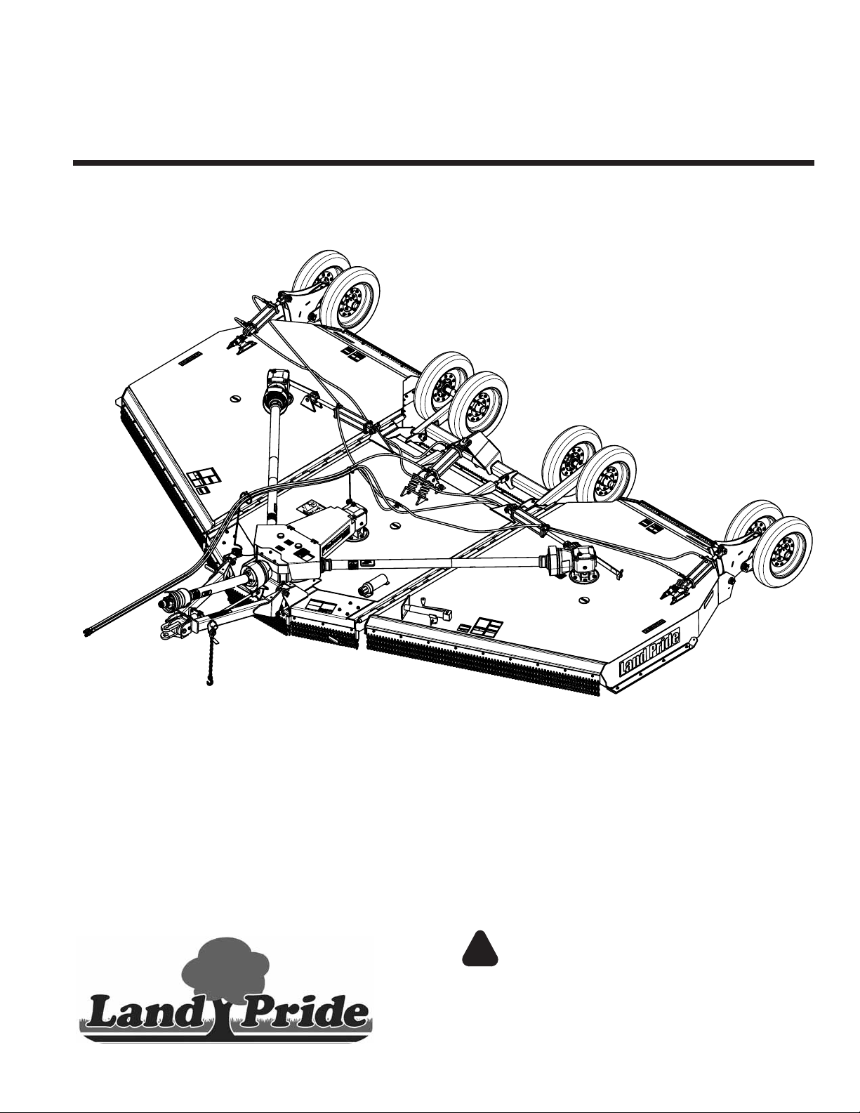
Table of Contents
Rotary Cuters
RC3620 & RCM3620
330-841M
Operator’s Manual
Read the Operator’s Manual entirely. When you see this symbol,
the subsequent instructions and warnings are serious - follow
!
without exception. Your life and the lives of others depend on it!
Cover photo may show optional equipment not supplied
with standard unit.
For an Operator’s Manual and Decal Kit in French
Language, please see your Land Pride dealer.
Printed 9/25/18
33853
Page 2
Machine Identification
Record your machine details in the log below. If you replace this manual, be sure to transfer this information to the new
manual.
If you, or the dealer, have added Options not originally ordered with the machine, or removed Options that were
originally ordered, the weights and measurements are no longer accurate for your machine. Update the record by
adding the machine weight and measurements provided in the Specifications & Capacities Section of this manual with
the Option(s) weight and measurements.
Model Number
Serial Number
Machine Height
Machine Length
Machine Width
Machine Weight
Delivery Date
First Operation
Accessories
Dealer Contact Information
Name:
Street:
City/State:
Telephone:
Email:
!
WARNING: Cancer and reproductive harm - www.P65Warnings.ca.gov
9/25/18RC3620 & RCM3620 Rotary Cuters 330-841M
Page 3

Table of Contents
Table of Contents
Important Safety Information . . . . . . . . . . . . . 1
Safety at All Times . . . . . . . . . . . . . . . . . . . . . . . . . 1
Look for the Safety Alert Symbol . . . . . . . . . . . . . . . 1
Safety Labels . . . . . . . . . . . . . . . . . . . . . . . . . . . . . 4
Introduction . . . . . . . . . . . . . . . . . . . . . . . . . . 12
Application . . . . . . . . . . . . . . . . . . . . . . . . . . . . . . 12
Using This Manual . . . . . . . . . . . . . . . . . . . . . . . . 12
Owner Assistance . . . . . . . . . . . . . . . . . . . . . . . . . 12
Serial Number . . . . . . . . . . . . . . . . . . . . . . . . . . 12
Section 1: Assembly & Set-up . . . . . . . . . . . 13
Tractor Requirements . . . . . . . . . . . . . . . . . . . . . . 13
Horsepower . . . . . . . . . . . . . . . . . . . . . . . . . . . . 13
Drawbar Set-up . . . . . . . . . . . . . . . . . . . . . . . . . 13
Hydraulic Set-up . . . . . . . . . . . . . . . . . . . . . . . . 13
Torque Requirements . . . . . . . . . . . . . . . . . . . . . . 13
Before You Start . . . . . . . . . . . . . . . . . . . . . . . . . . 13
Hitch Types . . . . . . . . . . . . . . . . . . . . . . . . . . . . . . 14
Hitch Assembly . . . . . . . . . . . . . . . . . . . . . . . . . . . 15
Park Jack Assembly . . . . . . . . . . . . . . . . . . . . . . . 16
Driveline Assembly . . . . . . . . . . . . . . . . . . . . . . . . 16
Tractor Shutdown Procedure . . . . . . . . . . . . . . . . 17
Standard Clevis Hitch Hook-Up . . . . . . . . . . . . . . . 17
LP Performance Hitch Hook-up . . . . . . . . . . . . . . . 18
Bar-Tite Hitch Hook-up . . . . . . . . . . . . . . . . . . . . . 19
Driveline Hook-up . . . . . . . . . . . . . . . . . . . . . . . . . 20
Hydraulic Hook-up . . . . . . . . . . . . . . . . . . . . . . . . . 20
Rephasing Lift Cylinders & Plumbing . . . . . . . . . . 21
Folding Cylinders & Plumbing . . . . . . . . . . . . . . . . 21
Remove Shipping Crossbar . . . . . . . . . . . . . . . . . 22
Unfold Wings . . . . . . . . . . . . . . . . . . . . . . . . . . . . . 22
Relocate Wing Lift Cylinder Mounts . . . . . . . . . . . 23
Driveline Clearance Check . . . . . . . . . . . . . . . . . . 24
Purge Hydraulic System . . . . . . . . . . . . . . . . . . . . 24
Hook-up LED Lights . . . . . . . . . . . . . . . . . . . . . . . 25
Unhook Rotary Cutter . . . . . . . . . . . . . . . . . . . . . . 26
Section 2: Adjustments . . . . . . . . . . . . . . . . . 28
LP Performance Hitch Pin Diameter . . . . . . . . . . . 28
Level Cutter Decks . . . . . . . . . . . . . . . . . . . . . . . . 28
Level Center Deck . . . . . . . . . . . . . . . . . . . . . . . 28
Level Wing Deck . . . . . . . . . . . . . . . . . . . . . . . . 29
Adjust Deck Cutting Height . . . . . . . . . . . . . . . . . . 29
Section 3: Operating Instructions . . . . . . . . . 30
Startup Checklist . . . . . . . . . . . . . . . . . . . . . . . . . . 30
Safety Information . . . . . . . . . . . . . . . . . . . . . . . . . 30
Avoid Extreme Turning Angles . . . . . . . . . . . . . . 31
Tractor & Cutter Inspection . . . . . . . . . . . . . . . . . . 32
Blade Operation Inspection . . . . . . . . . . . . . . . . . . 32
Transport Locks . . . . . . . . . . . . . . . . . . . . . . . . . . . 33
Transporting . . . . . . . . . . . . . . . . . . . . . . . . . . . . . 33
Road Side Cutting . . . . . . . . . . . . . . . . . . . . . . . . . 33
Field Set-up . . . . . . . . . . . . . . . . . . . . . . . . . . . . . . 34
Field Inspection . . . . . . . . . . . . . . . . . . . . . . . . . 34
Unfold Wings and Set Deck Cutting Height . . . . 34
Set Wing Folding Lever In Float Position . . . . . . 34
Rephasing Lift Cylinders . . . . . . . . . . . . . . . . . . 34
Select Gear Range . . . . . . . . . . . . . . . . . . . . . . . 34
Engage Blades . . . . . . . . . . . . . . . . . . . . . . . . . . 35
Disengage Blades . . . . . . . . . . . . . . . . . . . . . . . 35
General Operating Instructions . . . . . . . . . . . . . . . 36
Section 4: Options & Accessories . . . . . . . . .37
Safety Guards . . . . . . . . . . . . . . . . . . . . . . . . . . . . 37
Tire Options . . . . . . . . . . . . . . . . . . . . . . . . . . . . . . 37
Hitch Options . . . . . . . . . . . . . . . . . . . . . . . . . . . . . 37
Hydraulic Accessories . . . . . . . . . . . . . . . . . . . . . . 38
Hydraulic Wing Control Kit . . . . . . . . . . . . . . . . . 38
Selector Control Valve Kit . . . . . . . . . . . . . . . . . 38
Section 5: Maintenance & Lubrication . . . . . 39
General Maintenance Information . . . . . . . . . . . . . 39
Hydraulic System . . . . . . . . . . . . . . . . . . . . . . . . . 39
Tires . . . . . . . . . . . . . . . . . . . . . . . . . . . . . . . . . . . 39
Skid Shoes . . . . . . . . . . . . . . . . . . . . . . . . . . . . . . 40
Cutter Blades . . . . . . . . . . . . . . . . . . . . . . . . . . . . . 41
Drivelines With Slip Clutches . . . . . . . . . . . . . . . . . 43
Long-Term Storage . . . . . . . . . . . . . . . . . . . . . . . . 46
Ordering Replacement Parts . . . . . . . . . . . . . . . . . 46
Lubrication Points . . . . . . . . . . . . . . . . . . . . . . . . . 47
Axle Hub Bearing . . . . . . . . . . . . . . . . . . . . . . . . 47
Center Axle Pivots . . . . . . . . . . . . . . . . . . . . . . . 47
Wing Axle Pivots . . . . . . . . . . . . . . . . . . . . . . . . 47
Hitch Frame . . . . . . . . . . . . . . . . . . . . . . . . . . . . 48
Bar-Tite Hitch (Optional) . . . . . . . . . . . . . . . . . . . 48
Gearbox . . . . . . . . . . . . . . . . . . . . . . . . . . . . . . . 49
Divider Box . . . . . . . . . . . . . . . . . . . . . . . . . . . . . 49
Wing Driveline Profile Tubes . . . . . . . . . . . . . . . 50
Wing Driveline Joints . . . . . . . . . . . . . . . . . . . . . 50
Intermediate Driveline Joints . . . . . . . . . . . . . . . 51
Conventional Main Driveline Profile Tubes . . . . . 51
Conventional Main Driveline Joints . . . . . . . . . . 51
CV Main Driveline Profile Tubes . . . . . . . . . . . . . 52
CV Main Driveline Joints . . . . . . . . . . . . . . . . . . 52
9/25/18
Continue Table of Contents on next page
© Copyright 2018 All rights Reserved
Land Pride provides this publication “as is” without warranty of any kind, either expressed or implied. While every precaution has been taken in the
preparation of this manual, Land Pride assumes no responsibility for errors or omissions. Neither is any liability assumed for damages resulting from the use
of the information contained herein. Land Pride reserves the right to revise and improve its products as it sees fit. This publication describes the state of this
product at the time of its publication, and may not reflect the product in the future.
Land Pride is a registered trademark.
All other brands and product names are trademarks or registered trademarks of their respective holders.
Printed in the United States of America.
RC3620 & RCM3620 Rotary Cuters 330-841M
Page 4

Table of Contents
Table of Contents Continued
Section 6: Specifications & Capacities . . . . 54
Section 7: Features & Benefits . . . . . . . . . . . 56
Section 8: Troubleshooting . . . . . . . . . . . . . 57
Section 9: Torque & Tire Inflation Charts . . 58
Section 10: Warranty . . . . . . . . . . . . . . . . . . . 59
Parts Manual QR Locator
The QR (Quick Reference) code on the
cover and to the left will take you to the
Parts Manual for this equipment.
Download the appropriate App on your
smart phone, open the App, point your
phone on the QR code and take a picture.
RC3620 & RCM3620 Rotary Cuters 330-841M
Dealer QR Locator
The QR code on the left will
link you to available dealers
for Land Pride products.
Refer to Parts Manual QR
Locator on this page for
detailed instructions.
9/25/18
Page 5
Important Safety Information
Important Safety Information
Listed below are common practices that may or may not be applicable to the products
described in this manual.
Safety at All Times
Careful operation is your best
assurance against an accident.
All operators, no matter how much
experience they may have, should
carefully read this manual and
other related manuals, or have the
manuals read to them, before
operating the power machine and
this implement.
Thoroughly read and understand
the “Safety Label” section. Read
all instructions noted on them.
Do not operate the equipment
while under the influence of drugs
or alcohol as they impair the ability
to safely and properly operate the
equipment.
The operator should be familiar
with all functions of the tractor and
attached implement and be able to
handle emergencies quickly.
Make sure all guards and shields
appropriate for the operation are in
place and secured before
operating implement.
Keep all bystanders away from
equipment and work area.
Start tractor from the driver’s seat
with hydraulic controls in neutral.
Operate tractor and controls from
the driver’s seat only.
Never dismount from a moving
tractor or leave tractor unattended
with engine running.
Do not allow anyone to stand
between tractor and implement
while backing up to implement.
Keep hands, feet, and clothing
away from power-driven parts.
While transporting and operating
equipment, watch out for objects
overhead and along side such as
fences, trees, buildings, wires, etc.
Do not turn tractor so tight as to
cause hitched implement to ride
up on the tractor’s rear wheel.
Store implement in an area where
children normally do not play.
When needed, secure attachment
against falling with support blocks.
Look for the Safety Alert Symbol
The SAFETY ALERT SYMBOL indicates there is a
potential hazard to personal safety involved and extra
safety precaution must be taken. When you see this
!
Be Aware of
Signal Words
A signal word designates a degree or
level of hazard seriousness. The
signal words are:
!
DANGER
Indicates a hazardous situation that, if
not avoided, will result in death or
serious injury.
Safety Precautions for
Children
Tragedy can occur if the operator
is not alert to the presence of
children. Children generally are
attracted to implements and their
work.
Never assume children will remain
where you last saw them.
Keep children out of the work area
and under the watchful eye of a
responsible adult.
Be alert and shut the implement
and tractor down if children enter
the work area.
Never carry children on the tractor
or implement. There is not a safe
place for them to ride. They may
fall off and be run over or interfere
with the control of the power
machine.
Never allow children to operate the
power machine, even under adult
supervision.
Never allow children to play on the
power machine or implement.
Use extra caution when backing
up. Before the tractor starts to
move, look down and behind to
make sure the area is clear.
symbol, be alert and carefully read the message that
follows it. In addition to design and configuration of
equipment, hazard control, and accident prevention are
dependent upon the awareness, concern, prudence, and
proper training of personnel involved in the operation,
transport, maintenance, and storage of equipment.
!
WARNING
Indicates a hazardous situation that, if
not avoided, could result in death or
serious injury.
!
CAUTION
Indicates a hazardous situation that, if
not avoided, may result in minor or
moderate injury.
Tractor Shutdown & Storage
If engaged, disengage power
take-off.
Park on solid, level ground and
lower implement to ground or onto
support blocks.
Put tractor in park or set park
brake, turn off engine, and remove
switch key to prevent unauthorized
starting.
Relieve all hydraulic pressure to
auxiliary hydraulic lines.
Wait for all components to stop
before leaving operator’s seat.
Use steps, grab-handles and
anti-slip surfaces when stepping
on and off the tractor.
Detach and store implement in an
area where children normally do
not play. Secure implement using
blocks and supports.
OFF
REMOVE
9/25/18
1
Page 6
Important Safety Information
Listed below are common practices that may or may not be applicable to the products
described in this manual.
Tire Safety
Tire changing can be dangerous
and must be performed by
trained personnel using the
correct tools and equipment.
Always maintain correct tire
pressure. Do not inflate tires
above recommended pressures
shown in the Operator’s Manual.
When inflating tires, use a clip-on
chuck and extension hose long
enough to allow you to stand to
one side and NOT in front of or
over the tire assembly. Use a
safety cage if available.
Securely support the implement
when changing a wheel.
When removing and installing
wheels, use wheel handling
equipment adequate for the
weight involved.
Make sure wheel bolts have been
tightened to the specified torque.
Transport Safely
Comply with federal, state, and
local laws.
Use towing vehicle and trailer of
adequate size and capacity. Secure
equipment towed on a trailer with
tie downs and chains.
Sudden braking can cause a towed
trailer to swerve and upset. Reduce
speed if towed trailer is not
equipped with brakes.
Avoid contact with any overhead
utility lines or electrically charged
conductors.
Always drive with load on end of
loader arms low to the ground.
Always drive straight up and down
steep inclines with heavy end of a
tractor with loader attachment on
the “uphill” side.
Engage park brake when stopped
on an incline.
Maximum transport speed for an
attached equipment is 20 mph. DO
NOT EXCEED. Never travel at a
speed which does not allow
adequate control of steering and
stopping. Some rough terrains
require a slower speed.
As a guideline, use the following
maximum speed weight ratios for
attached equipment:
20 mph when weight of attached
equipment is less than or equal
to the weight of machine towing
the equipment.
10 mph when weight of attached
equipment exceeds weight of
machine towing equipment but
not more than double the weight.
IMPORTANT: Do not tow a load
that is more than double the weight
of the vehicle towing the load.
Use A Safety Chain
A safety chain will help control
drawn machinery should it
separate from the tractor drawbar.
Use a chain with the strength
rating equal to or greater than the
gross weight of the towed
implement.
Attach the chain to the tractor
drawbar support or other specified
anchor location. Allow only
enough slack in the chain to
permit turning.
Always hitch the implement to the
machine towing it. Do not use the
safety chain tow the implement.
Practice Safe Maintenance
Understand procedure before doing
work. Refer to the Operator’s
Manual for additional information.
Work on a level surface in a clean
dry area that is well-lit.
Lower implement to the ground and
follow all shutdown procedures
before leaving the operator’s seat to
perform maintenance.
Do not work under any hydraulic
supported equipment. It can settle,
suddenly leak down, or be lowered
accidentally. If it is necessary to
work under the equipment, securely
support it with stands or suitable
blocking beforehand.
Use properly grounded electrical
outlets and tools.
Use correct tools and equipment for
the job that are in good condition.
Allow equipment to cool before
working on it.
Disconnect battery ground cable (-)
before servicing or adjusting
electrical systems or before welding
on implement.
Inspect all parts. Make certain
parts are in good condition &
installed properly.
Replace parts on this implement
with genuine Land Pride parts only.
Do not alter this implement in a way
which will adversely affect its
performance.
Do not grease or oil implement
while it is in operation.
Remove buildup of grease, oil, or
debris.
Always make sure any material and
waste products from the repair and
maintenance of the implement are
properly collected and disposed.
Remove all tools and unused parts
before operation.
Do not weld or torch on galvanized
metal as it will release toxic fumes.
2
9/25/18
Page 7
Important Safety Information
Listed below are common practices that may or may not be applicable to the products
described in this manual.
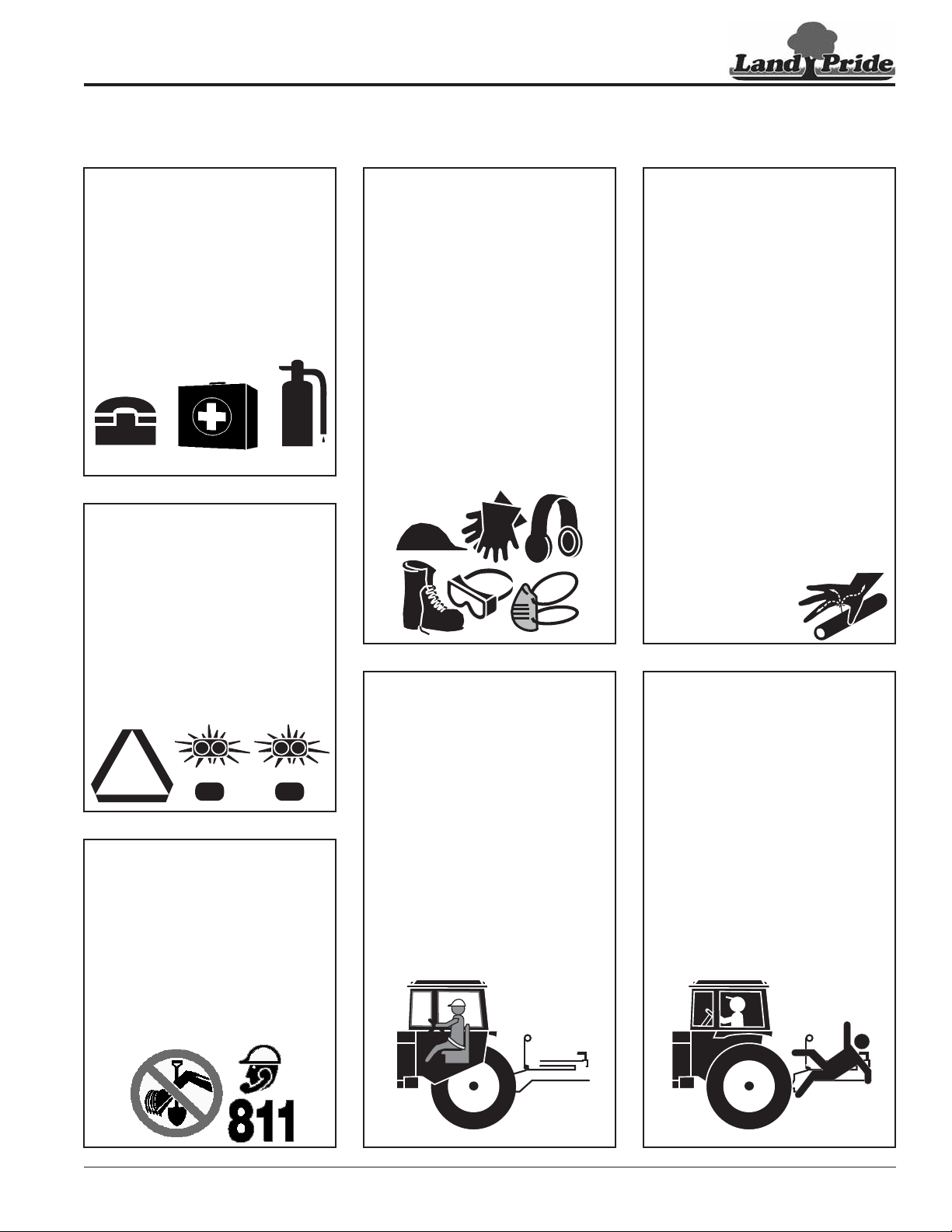
Prepare for Emergencies
Be prepared if a fire starts.
Keep a first aid kit and fire
extinguisher handy.
Keep emergency numbers for
doctor, ambulance, hospital, and
fire department near phone.
911
Use Safety
Lights and Devices
Slow moving tractors, skid steers,
self-propelled machines, and towed
equipment can create a hazard
when driven on public roads. They
are difficult to see, especially at
night. Use the Slow Moving Vehicle
sign (SMV) when on public roads.
Flashing warning lights and turn
signals are recommended
whenever driving on public roads.
Avoid Underground
Utilities
Dig Safe, Call 811 (USA).
Always contact your local utility
companies (electrical, telephone,
gas, water, sewer, and others)
before digging so that they may
mark the location of any
underground services in the area.
Be sure to ask how close you can
work to the marks they positioned.
Wear Personal Protective
Equipment (PPE)
Wear protective clothing and
equipment appropriate for the job
such as safety shoes, safety
glasses, hard hat, and ear plugs.
Clothing should fit snug without
fringes and pull strings to avoid
entanglement with moving parts.
Prolonged exposure to loud noise
can cause hearing impairment or
hearing loss. Wear suitable
hearing protection such as
earmuffs or earplugs.
Operating equipment safely
requires the operator’s full
attention. Avoid wearing
headphones while operating
equipment.
Use Seat Belt and ROPS
Land Pride recommends the use
of a CAB or roll-over-protectivestructures (ROPS) and seat belt
in almost all power machines.
Combination of a CAB or ROPS
and seat belt will reduce the risk
of serious injury or death if the
power machine should be upset.
If ROPS is in the locked-up
position, fasten seat belt snugly
and securely to help protect
against serious injury or death
from falling and machine overturn.
Avoid High
Pressure Fluids Hazard
Escaping fluid under pressure can
penetrate the skin causing serious
injury.
Before disconnecting hydraulic
lines or performing work on the
hydraulic system, be sure to
release all residual pressure.
Make sure all hydraulic fluid
connections are tight and all
hydraulic hoses and lines are in
good condition before applying
pressure to the system.
Use a piece of paper or
cardboard, NOT BODY PARTS, to
check for suspected leaks.
Wear protective gloves and safety
glasses or goggles when working
with hydraulic systems.
DO NOT DELAY. If an accident
occurs, see a doctor familiar with
this type of injury immediately. Any
fluid injected into the skin or eyes
must be treated within
a few hours or
gangrene may
result.
Keep Riders Off
Machinery
Never carry riders on tractor or
implement.
Riders obstruct operator’s view
and interfere with the control of
the power machine.
Riders can be struck by objects or
thrown from the equipment.
Never use tractor or implement to
lift or transport riders.
9/25/18
3
Page 8
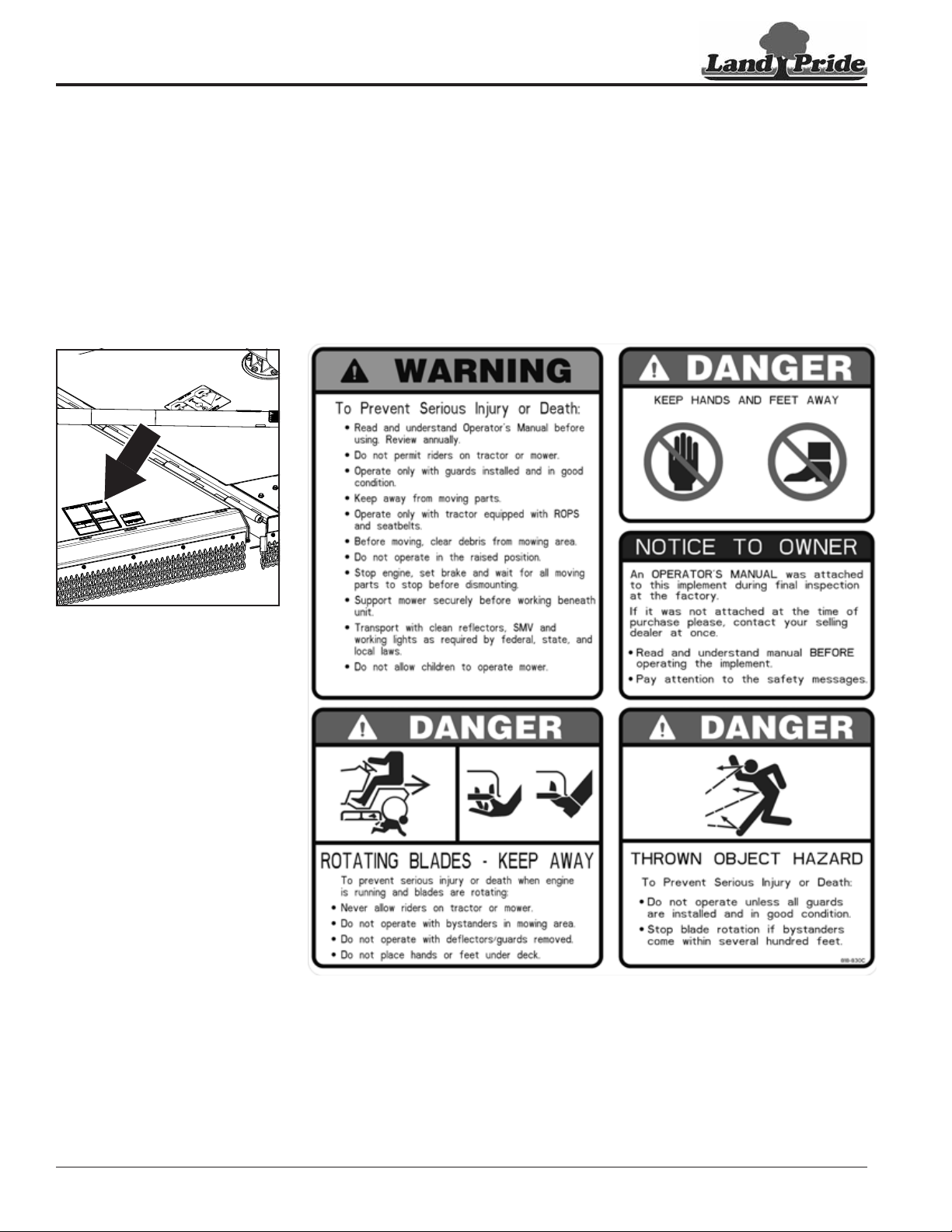
Table of Contents
Important Safety Information
Important Safety Information
Safety Labels
Your Rotary Cutter comes equipped with all safety labels in
place. They were designed to help you safely operate your
implement. Read and follow their directions.
1. Keep all safety labels clean and legible.
2. Refer to this section for proper label placement. Replace
all damaged or missing labels. Order new labels from your
nearest Land Pride dealer. To find your nearest dealer,
visit our dealer locator at www.landpride.com.
3. Some new equipment installed during repair requires
safety labels to be affixed to the replaced component as
33858
specified by Land Pride. When ordering new components
make sure the correct safety labels are included in the
request.
4. Refer to this section for proper label placement.
To install new labels:
a. Clean surface area where label is to be placed.
b. Spray soapy water onto the cleaned area.
c. Peel backing from label and press label firmly onto the
surface.
d. Squeeze out air bubbles with edge of a credit card or
with a similar type of straight edge.
818-830C
Safety Combo
2 - Places: Right and left wings
4
RC3620 & RCM3620 Rotary Cuters 330-841M 9/25/18
Page 9
Important Safety Information
33854
33858
Table of Contents
33854
33855
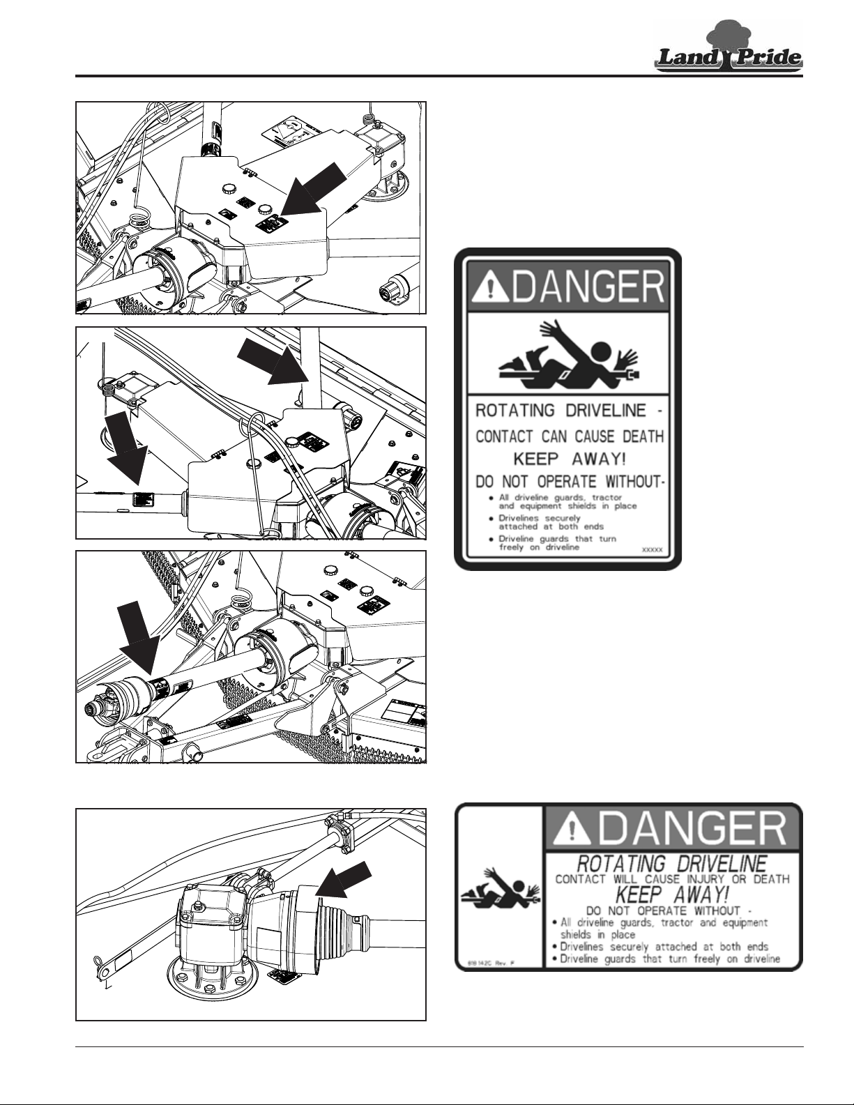
818-552C
Danger! Rotating Driveline - Keep Away
1 - Place: Top of splitter shield
3 - Places: Main driveline and 2-wing drivelines
818-142C
Danger! Rotating Driveline - Keep Away
2 - Places: Right and left wing gearbox shields
RC3620 & RCM3620 Rotary Cuters 330-841M9/25/18
5
Page 10
Important Safety Information
22296
33855
Table of Contents
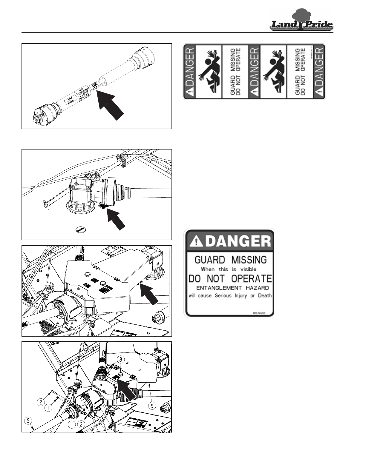
818-540C
Danger! Guard Missing - Do Not Operate
3 - Places: Main driveline and 2-wing drivelines
33854
37999
818-543C
Danger! Guard Missing - DO NOT Operate
4 - Places:
Beneath the 3 spindle gearbox shaft guards
Beneath hinged guard (#9)
6
RC3620 & RCM3620 Rotary Cuters 330-841M 9/25/18
Page 11
Important Safety Information
33854
33854
Table of Contents
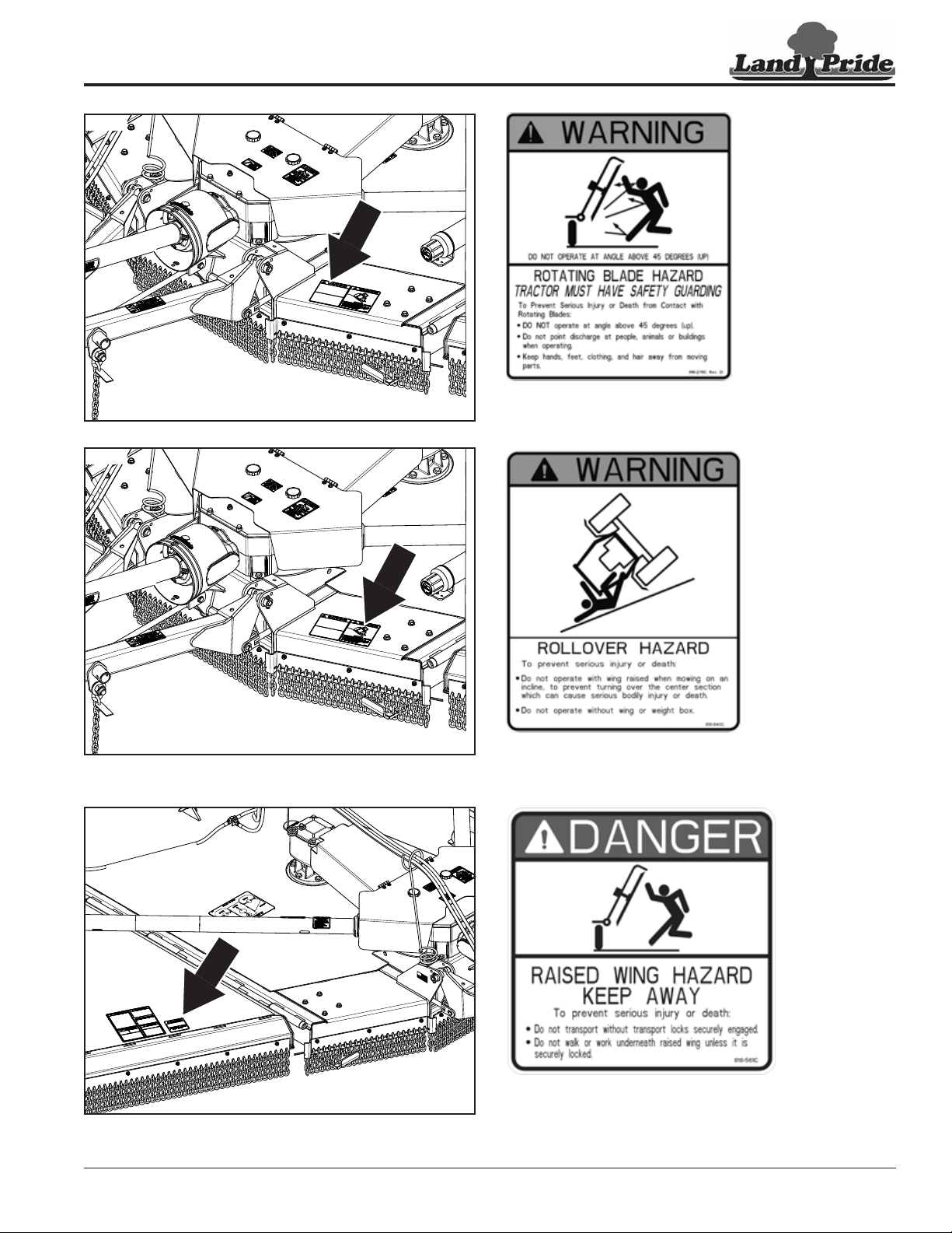
818-276C
Warning! Rotating Blade Hazard (Left side Only)
33858
818-840C
Warning! Rollover Hazard (Left side only)
818-561C
Danger! Raised Wing Hazard
2-Places: Right and left wings
RC3620 & RCM3620 Rotary Cuters 330-841M9/25/18
7
Page 12
Important Safety Information
33854
33854
Table of Contents
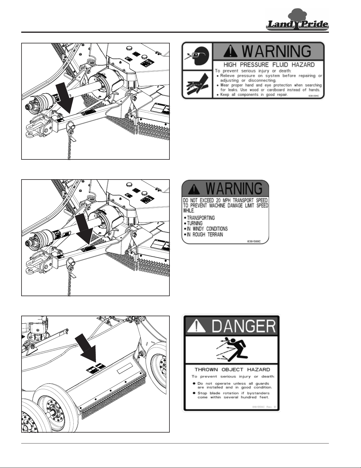
838-094C
Warning! High Pressure
1 - Place: On A-frame hitch
33856
838-588C
Warning! Folding Cutter Speed Warning
1 - Place: On A-frame hitch
818-556C
Danger! Thrown Object Hazard
2 - Places: Right and left wings
8
RC3620 & RCM3620 Rotary Cuters 330-841M 9/25/18
Page 13
Important Safety Information
33856
33857
Table of Contents
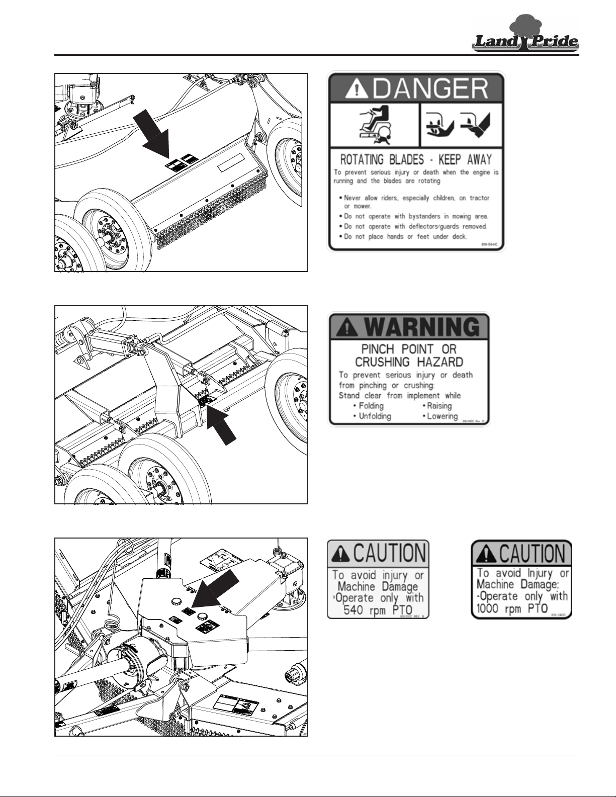
818-564C
Danger! Rotating Blade
2 - Places: Right and left wings
33854
818-045C
Warning! Pinch Point or Crushing Hazard
1 - Place: Back of center axle
818-130C
Caution! Use 540 rpm power take-off
(RC3620 cutters only)
818-240C
Caution! Use 1000 rpm power take-offpower take-off
(RCM3620 cutters only)
RC3620 & RCM3620 Rotary Cuters 330-841M9/25/18
9
Page 14
Important Safety Information
33855
33856
Table of Contents
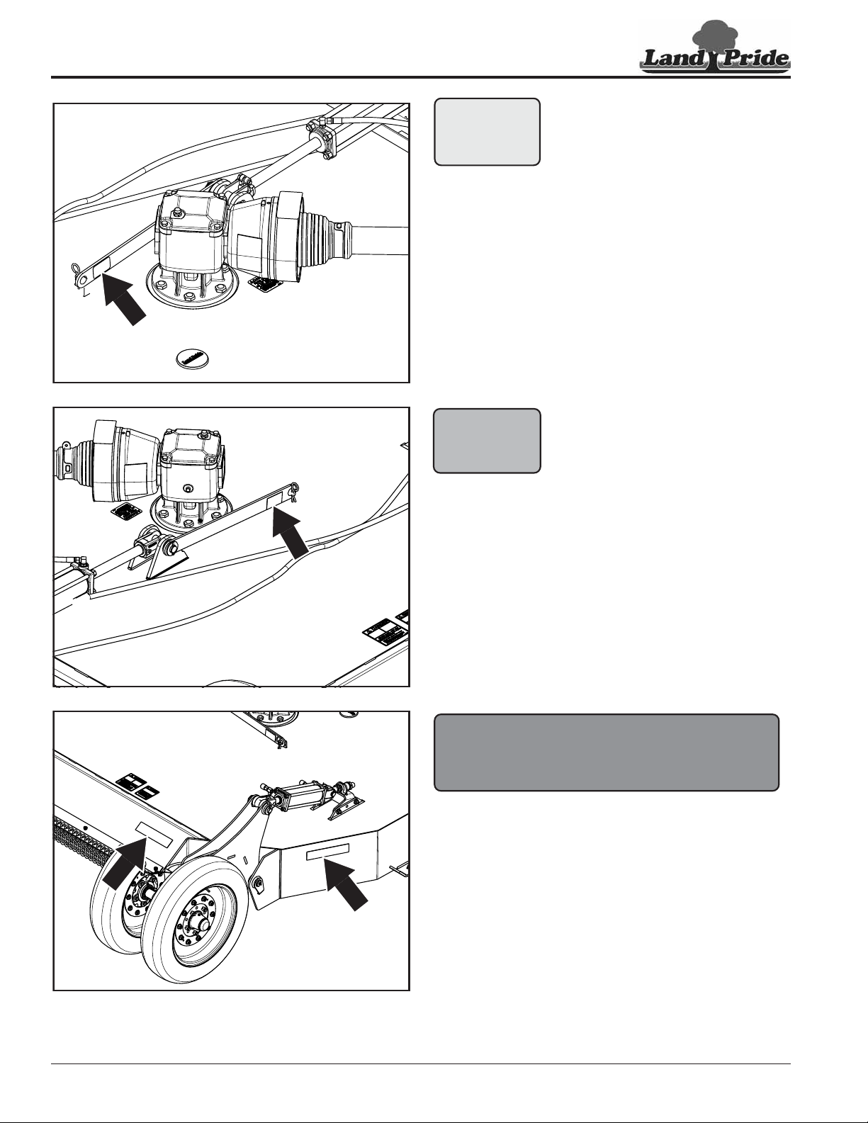
818-229C
Amber Reflector
2 - Places; Front side of cylinder transport locks
35928
818-230C
Red Reflector
2 - Places: Back side of cylinder transport locks
838-614C
2" x 9" Red Reflector
2 - Places: On right wing
2 - Places: On left wing
10
RC3620 & RCM3620 Rotary Cuters 330-841M 9/25/18
Page 15
Important Safety Information
35928
35927
Table of Contents
838-615C
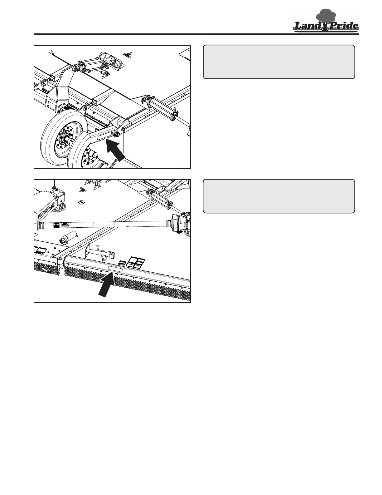
2" x 9" Amber Reflector
2 - Places: On left and right arms of center axle
838-615C
2" x 9" Amber Reflector
1 - Place: On front face of left wing
RC3620 & RCM3620 Rotary Cuters 330-841M9/25/18
11
Page 16
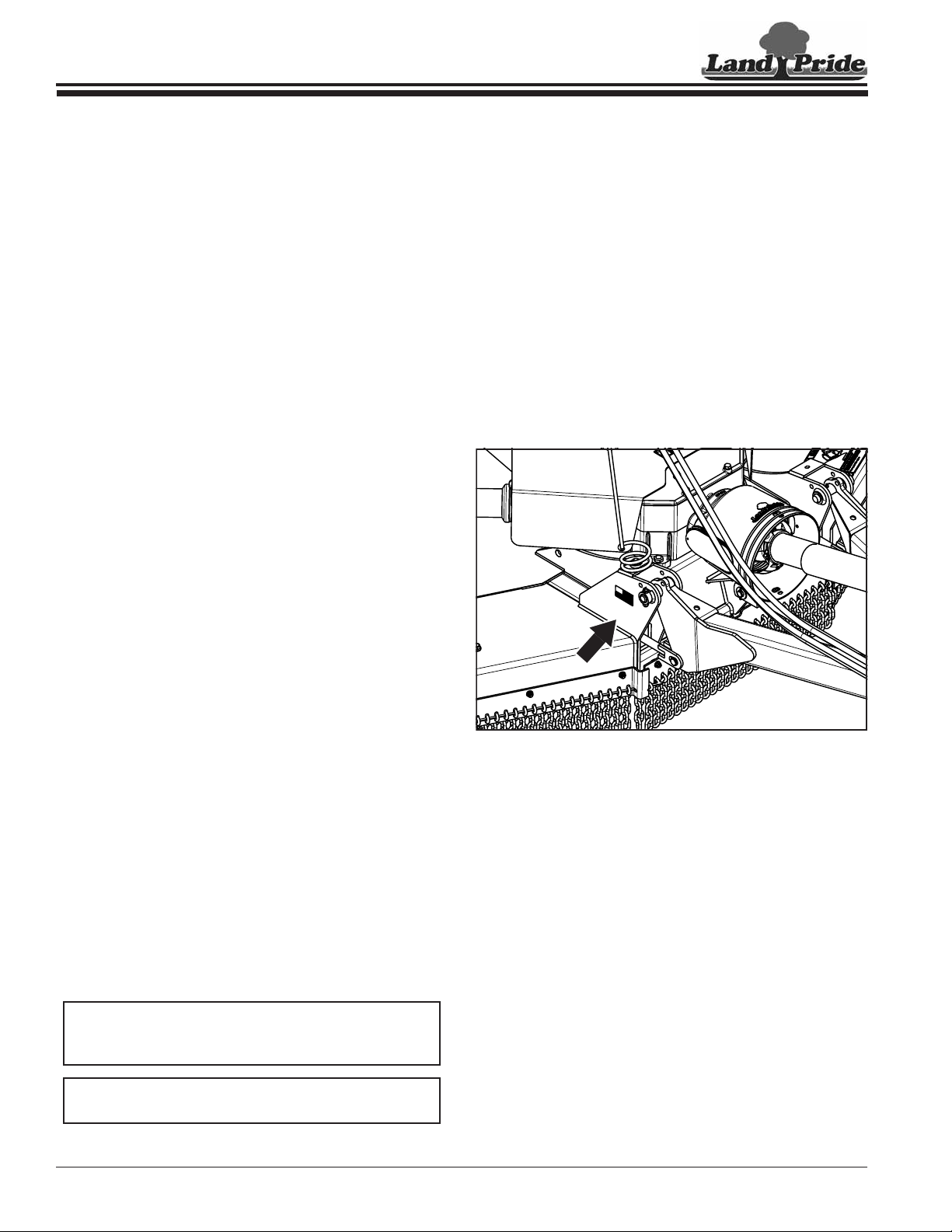
Table of Contents
Introduction Important Safety Information
Introduction
Land Pride welcomes you to the growing family of new
product owners. This Rotary Cutter has been designed
with care and built by skilled workers using quality
materials. Proper assembly, maintenance, and safe
operating practices will help you get years of satisfactory
use from this Rotary Cutter.
Application
The RC3620 and RCM3620 Series Rotary Cutters are
designed and built by Land Pride to provide excellent
cutting performance on gently sloping or slightly
contoured right-of-ways, pastures, and set-aside-acres.
The 20' cutting width, 2" to 12" cutting height and ability to
cut weeds and brush up to 2" in diameter make them well
suited for these applications.
Both models offer pull-type, self-leveling clevis hitch, and
Cat. 5 conventional or Cat. 6 constant velocity main
driveline for attachment to 70-160 hp tractors. The
RC3620 attaches to tractors with 540 rpm power take-off
speed and RCM3620 attaches to tractors with 1000 rpm
power take-off speed. They are also offered with various
hitch and tire options making them an excellent choice for
agricultural, airport, and municipal mowing applications.
See “Specifications & Capacities” on page 54 and
“Features & Benefits” on page 56 for additional
information and performance enhancing options.
Owner Assistance
The dealer should complete the Online Warranty
Registration at the time of purchase. This information is
necessary to provide you with quality customer service.
The parts on your Rotary Cutter have been specially
designed by Land Pride and should only be replaced with
genuine Land Pride parts. Contact a Land Pride dealer if
customer service or repair parts are required. Your Land
Pride dealer has trained personnel, repair parts, and
equipment needed to service the implement.
Serial Number
For quick reference and prompt service, record model
and serial number on the inside cover page and again on
the warranty page. Always provide model number and
serial number when ordering parts and in all
correspondences with your Land Pride dealer. For
location of your serial number plate, see Figure 1.
Using This Manual
This Operator’s Manual is designed to help familiarize
•
the operator with safety, assembly, operation,
adjustments, troubleshooting, and maintenance. Read
this manual and follow the recommendations to help
ensure safe and efficient operation.
• The information contained within this manual was
current at the time of printing. Some parts may change
slightly to assure you of the best performance.
• To order a new Operator’s or Parts Manual, contact
your authorized dealer. Manuals can also be
downloaded, free-of-charge, from our website at
www.landpride.com.
• Store this manual in the dry storage tube located on the
center deck.
Terminology
“Right” or “Left” as used in this manual is determined by
facing forward in the direction the machine will operate
while in use unless otherwise stated.
Definitions
IMPORTANT: A special point of information related
to the following topic. Land Pride’s intention is this
information must be read & noted before continuing.
NOTE: A special point of information that the
operator should be aware of before continuing.
33858
Serial Number Plate Location
Figure 1
Further Assistance
Your dealer wants you to be satisfied with your new
cutter. If for any reason you do not understand any part of
this manual or are not satisfied with the service received,
the following actions are suggested:
1. Discuss any problems you have with your implement
with your dealership service personnel so they can
address the problem.
2. If you are still not satisfied, seek out the owner or
general manager of the dealership, explain the
problem, and request assistance.
3. For further assistance write to:
Land Pride Service Department
1525 East North Street
P.O. Box 5060
Salina, Ks. 67402-5060
E-mail address
12
RC3620 & RCM3620 Rotary Cuters 330-841M 9/25/18
Page 17
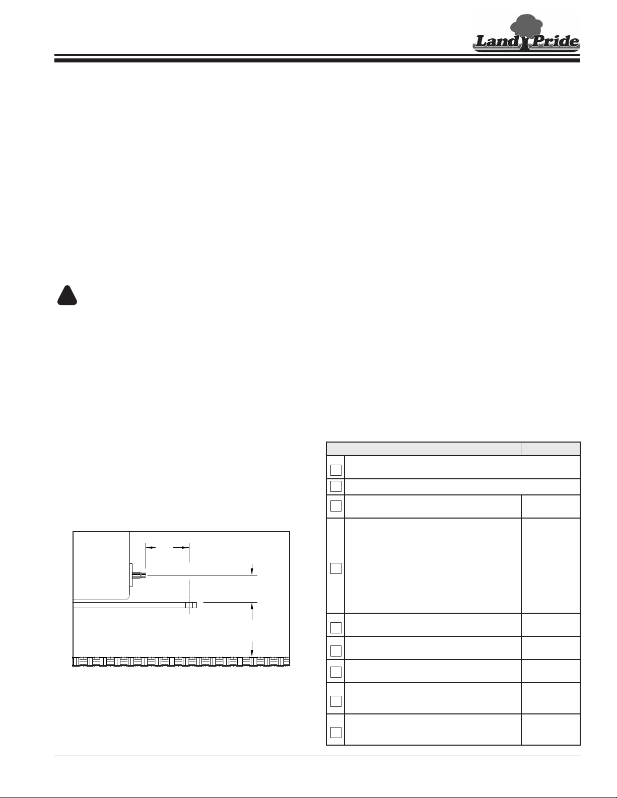
Table of Contents
Section 1: Assembly & Set-up
Section 1: Assembly & Set-up
Tractor Requirements
Horsepower
Tractor horsepower should be within the range noted
below. Tractors outside the range must not be used.
Horsepower rating . . . . . . . . . . . . . . . . . . . 70-160 hp
Hitch type (See Drawbar Set-up) . . . . . . . . . Drawbar
Rear power take-off speed:
RC3620. . . . . . . . . . . . . . . . . . . . . . . . . . . .540 rpm
RCM3620 . . . . . . . . . . . . . . . . . . . . . . . . . 1000 rpm
Hydraulic outlets (See Hydraulic Set-up)
Factory standard . . . . . . . . . . . . . . 2 Duplex outlets
Independent wing raising . . . . . . . 3 Duplex outlets
Electrical . . . . . . . . . . . . . . . . . . . . . . . . . 7-pin outlet
Drawbar Set-up
Refer to Figure 1-1:
!
WARNING
To avoid serious injury or death:
• Do not use a tractor that is too small or too large. Small
tractors can be pushed around and flipped over. Large
tractors can damage the attached implement.
• Do not use a power take-off adapter. The adapter will
increase strain on the tractor’s power take-off shaft causing
possible damage to shaft and driveline. It will also defeat
the purpose of the tractor’s power take-off shield.
• Power take-off damage may occur if distances “A” and
“B” are not properly maintained.
Maintain proper distance, dimension “A”, between center
of drawbar hitch pin hole and end of tractor power take-off
shaft.
540 rpm & 1 3/8" @ 1000 rpm power take-off speed:
“A” . . . . . . . . . . . . . . . . . . . . . . . . . . . . . . . . . 14"- 16"
“B” . . . . . . . . . . . . . . . . . . . . . . . . . . . . . . . . . 8" - 10"
“C” . . . . . . . . . . . . . . . . . . . . . . . . . . . . . . . 18" to 22"
22273
A
Power Take-Off Shaft
Drawbar
Ground Level
Power Take-Off to Drawbar Distance
Figure 1-1
B
C
Hydraulic Set-up
The number of tractor hydraulic duplex outlets is
dependent upon how the Rotary Cutter is set-up.
• Two duplex outlets are required if the wings are raised
and lowered simultaneously. (Factory standard)
• Three duplex outlets are required if the wings are
raised and lowered independently. (Requires
“Hydraulic Wing Control Kit” on page 38 to raise
wings independently.)
• If the tractor does not have the necessary number of
duplex outlets, there are control valve kits available to
add outlets. See “Selector Control Valve Kit” on page
38 for a complete description of the kits.
Torque Requirements
See “Torque Values Chart” on page 58 to determine
correct torque values when tightening hardware. See
“Additional Torque Values” at bottom of chart for
exceptions to common torque values.
Before You Start
Read and understand the operator’s manual for your
cutter. An understanding of how it works will aid in the
assembly and setup of your cutter.
It is best to go through the “Assembly Checklist” below
before assembling the cutter. Speed up your assembly
task and make the job safer by having all needed parts
and equipment readily at hand.
Assembly Checklist
Check Ref.
Have a fork lift or loader with properly sized chains and safety
stands capable of lifting and supporting the equipment on hand.
Have a minimum of two people available during assembly.
Make sure all major components and loose
parts are shipped with the machine.
Double check to make sure all parts, fasteners,
and pins are installed in the correct location.
Refer to the Parts Manual if unsure. By double
checking, you will lessen the chance of using a
bolt incorrectly that may be needed later.
NOTE: All assembled hardware from the factory
has been installed in the correct location.
Remember location of a part or fastener if
removed during assembly. Keep parts
separated.
Make sure working parts move freely, bolts are
tight & cotter pins are spread.
Make sure all grease fittings are in place and
lubricated.
Make sure all safety labels are correctly located
and legible. Replace if damaged.
Make sure all red and amber reflectors are
correctly located and visible when machine is in
transport position.
Make sure all tires are inflated to the specified
psi air pressure and all wheel bolts and axle
nuts are tightened to the specified torque.
Operator’s
Manual
Operator’s
Manual
330-841M
Parts Manual
330-841P
Operator’s
Manual
Page 47
Page 4
Page 10
Page 58
RC3620 & RCM3620 Rotary Cuters 330-841M9/25/18
13
Page 18
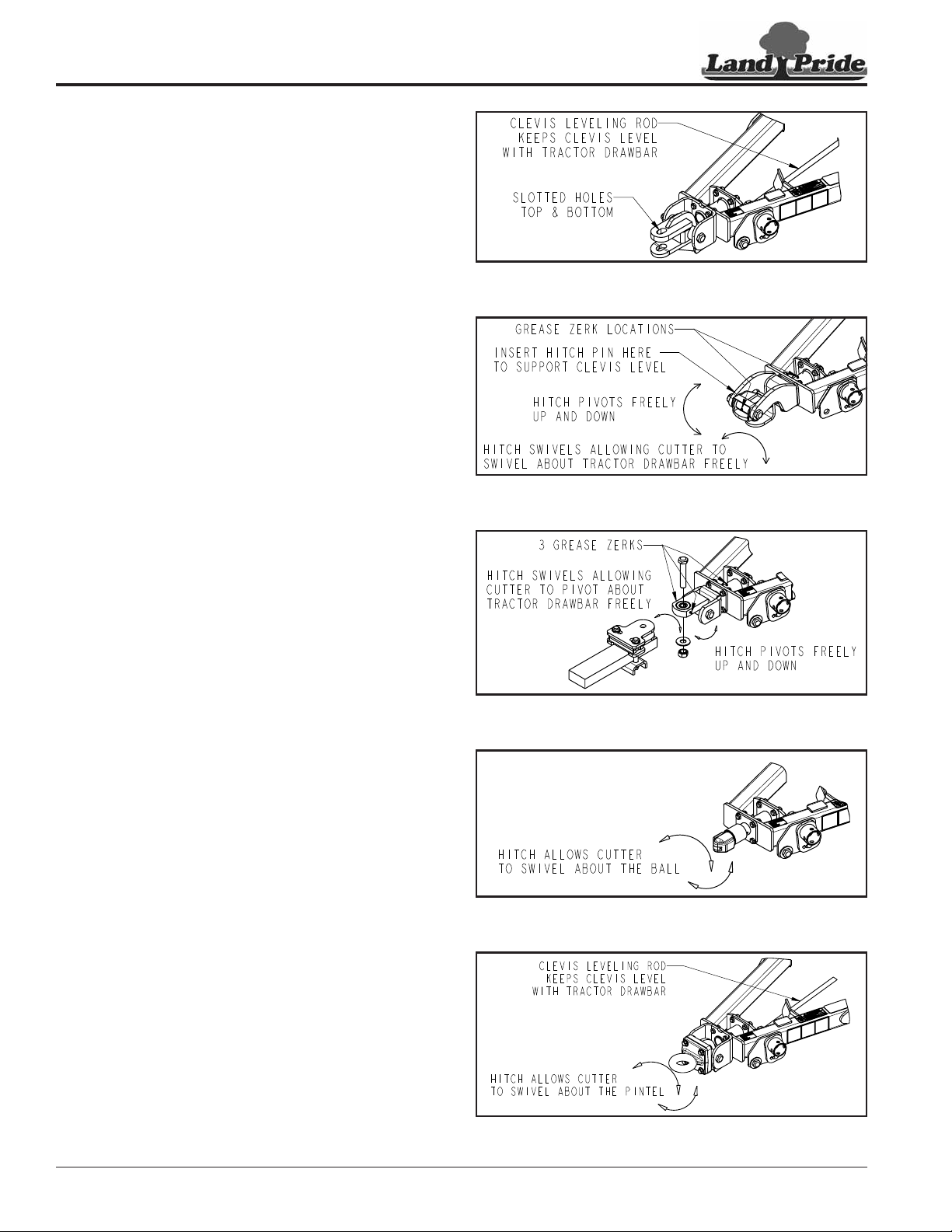
Table of Contents
Section 1: Assembly & Set-up
Hitch Types
The cutter is factory supplied with the standard clevis
hitch. Other optional hitches are available. They include
Land Pride Performance Hitch, bar-tite hitch, ball hitch,
and pintle hitch. See your nearest Land Pride dealer
should you want to change your hitch set-up.
Standard Clevis Hitch
Refer to Figure 1-2:
A clevis leveling rod attached to the underside of the
clevis keeps the clevis parallel with tractor drawbar at all
cutting heights. Cutter rotation about the tractor drawbar
is limited to slots located in the clevis’ upper and lower
plates and drawbar hole size.
Land Pride Performance Hitch (Optional)
Refer to Figure 1-3:
The LP Performance Hitch is a drawbar friendly,
self-leveling hitch that pivots up and down and side-toside. It is held upright with customer-supplied hitch pin to
allow single-person hook-up.
Bar-Tite Hitch (Optional)
Refer to Figure 1-4:
The bar-tite hitch functions similar to LP Performance
Hitch except it clamps directly to the drawbar. The bar-tite
hitch is sandwiched between hardened steel plates to
eliminate drawbar wear. It has a bushing in the tongue to
extend hitch life. Bushing and hitch swivel are greasable.
26596
Standard Clevis Hitch
Figure 1-2
37590
LP Performance Hitch
Figure 1-3
26599
Bar-Tite Hitch
Figure 1-4
Ball Hitch (Optional)
Refer to Figure 1-5:
Cutter rotation about the tractor drawbar is limited to
swivel movement over the 2 5/16" tractor mounted ball.
Ball Hitch
Figure 1-5
Pintle Hitch (Optional)
Refer to Figure 1-6:
A leveling rod attached to the underside of the pintle hitch
keeps the pintle parallel with the tractor drawbar at all
cutting heights. Cutter rotation about the tractor drawbar
is limited to movement about the pintle connection. The
pintle hitch is ideal for a drawbar hammer strap.
Pintle Hitch
Figure 1-6
14
RC3620 & RCM3620 Rotary Cuters 330-841M 9/25/18
26600
26602
Page 19
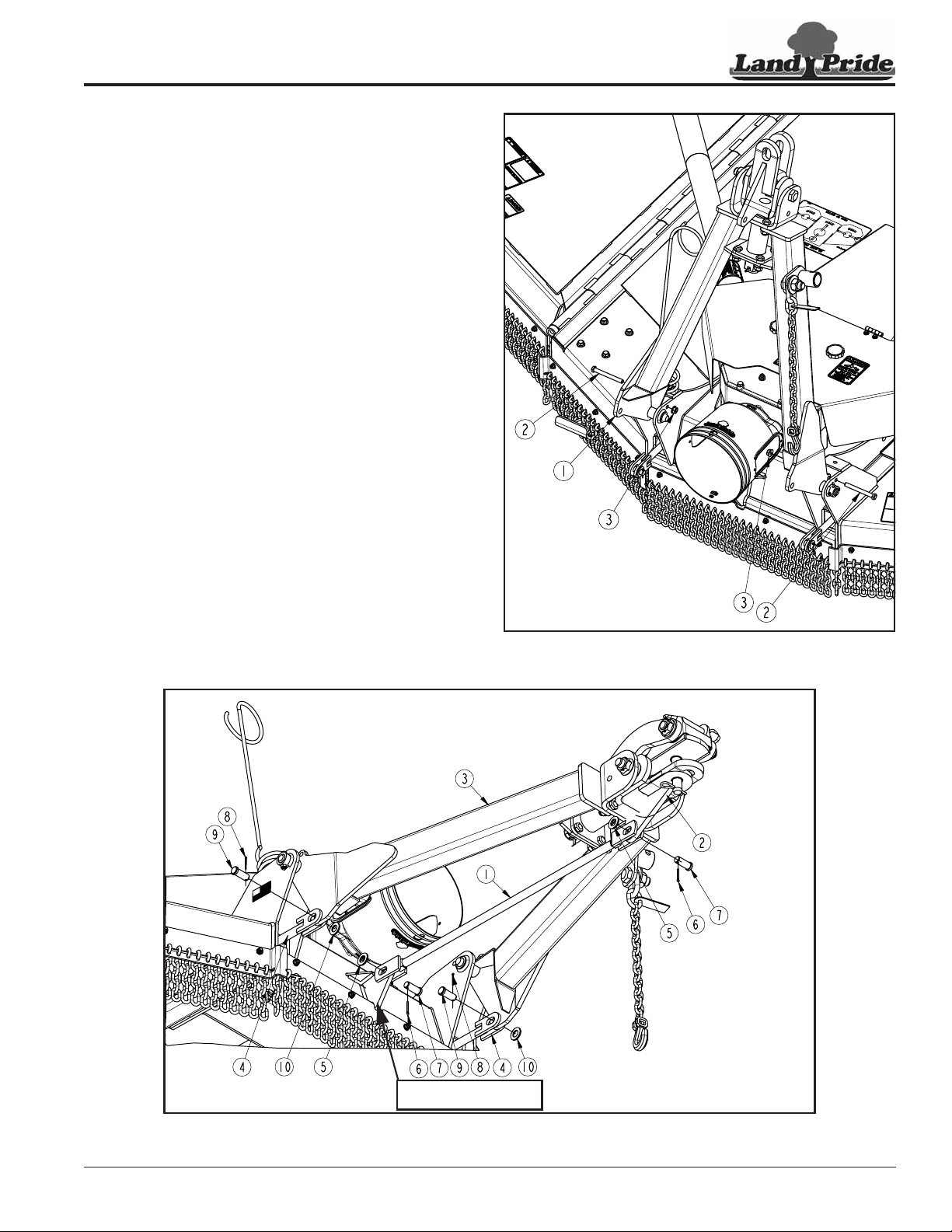
Table of Contents
Section 1: Assembly & Set-up
Hitch Assembly
Refer to Figure 1-7:
1. Remove and discard 1/2" hex whiz nuts (#3) and hex
head bolts (#2).
2. Rotate hitch (#1) down into pulling position as shown
in Figure 1-8.
Refer to Figure 1-8:
3. Instructions “a” & “b” below are for cutters equipped
with standard clevis or pintle hitch. Skip to step 4 if
assembling LP Performance, bar-tite, or ball hitch.
a. Attach clevis level rod (#1) to center deck lug and
clevis hitch (#2) with clevis pins (#7), flat
washers (#5), and cotter pins (#6).
b. Secure cotter pins (#6) by bending one or more
legs of each cotter pin.
4. Attach hitch frame (#3) to leveling rods (#4) by
inserting clevis pins (#9) into leveling rod clevises
and hitch frame (#3) as shown. Secure clevis pins
with flat washers (#10) and cotter pins (#8).
5. Leveling rod adjustment will be made later. See
“Level Cutter Decks” on page 28 for detailed
instructions.
Factory Shipped With Hitch Folded Up
Figure 1-7
33859
CENTER DECK LUG
Hitch Assembly
Figure 1-8
33860
RC3620 & RCM3620 Rotary Cuters 330-841M9/25/18
15
Page 20
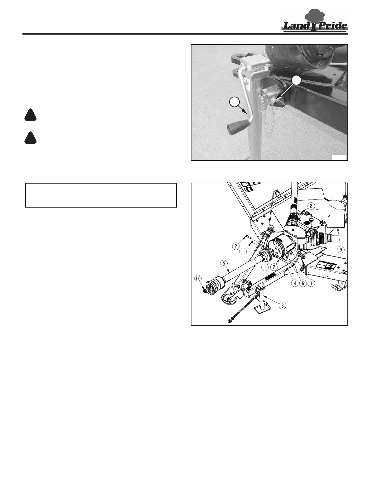
Table of Contents
Section 1: Assembly & Set-up
Park Jack Assembly
Refer to Figure 1-9:
Attach parking jack (#1) to hitch frame and secure with
attached detent pin (#2). Adjust jack up or down until
clevis hitch is at drawbar height.
Driveline Assembly
Refer to Figure 1-10:
!
WARNING
To avoid serious injury or death:
!
DANGER
To avoid serious injury or death: Make certain driveline
yokes are secur ely fastened at each end. A loose yoke can work
free allowing the driveline to rotate uncontrollably causing
implement damage and bodily injury or death to anyone
nearby.
IMPORTANT: The driveline must be lubricated
before putting it into service. Refer to “Lubrication
Points” on page 47.
2
1
22149
Parking Jack Assembly
Figure 1-9
The main driveline may be either constant velocity type
or conventional type. Pull-collar couplers and retaining
bolts are used to connect the driveline to the tractor and
implement gearbox, respectively.
1. Park tractor and cutter in a straight line on a level
surface. Place gear selector in park, shut tractor
engine off, set park brake, and remove switch key.
2. Verify “Drawbar Set-up” dimensions on page 13 are
correct before installing driveline.
3. Remove hand knobs (#8).
4. Rotate front half of splitter guard (#9) open.
5. Unsnap doors (#7) on both sides of splitter guard (#6)
and rotate doors down.
6. Remove and discard rubber shaft protector (#4) from
splitter gearbox input shaft.
7. Remove locknuts (#1) and bolts (#2) from bolted
coupler end of driveline (#5).
8. Slide bolted coupler end of driveline (#5) over splitter
gearbox input shaft until bolt holes in coupler align
with groove around input shaft.
9. Attach driveline (#5) to splitter gearbox input shaft
with removed bolts (#2) and locknuts (#1). Tighten
locknuts to the correct torque.
10. Pull on driveline yoke to ensure yoke is securely
fastened to splitter gearbox shaft.
11. Rotate doors (#7) up and snap shut.
12. Collapse driveline (#5) by pushing tractor end of
driveline toward splitter gearbox.
13. Rotate front half of splitter guard (#9) shut and s.
14. Secure splitter guard with hand knobs (#8).
37999
Driveline Assembly
Figure 1-10
16
RC3620 & RCM3620 Rotary Cuters 330-841M 9/25/18
Page 21
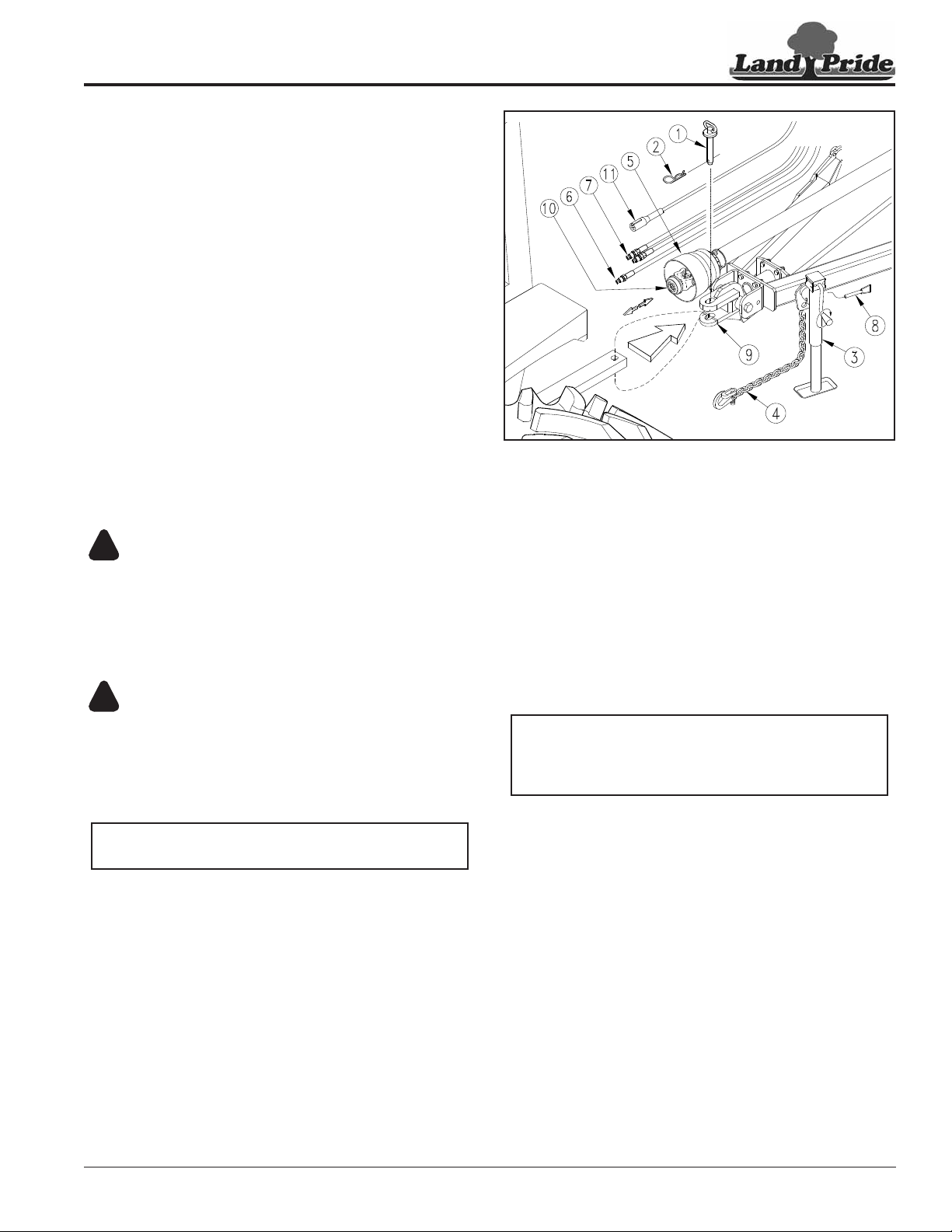
Table of Contents
Section 1: Assembly & Set-up
Tractor Shutdown Procedure
The following are basic tractor shutdown procedures.
Follow these procedures and any additional shutdown
procedures provided in your tractor Operator’s Manual
before leaving the operator’s seat.
1. Reduce engine speed and disengage power take-off
if engaged.
2. Park tractor and implement on level, solid ground.
3. Lower implement to ground or onto non-concrete
support blocks.
4. Put tractor in park or set park brake, turn off engine,
and remove switch key to prevent unauthorized
starting.
5. Relieve all hydraulic pressure to auxiliary hydraulic
lines.
6. Wait for all components to come to a complete stop
before leaving the operator’s seat.
7. Use steps, grab-handles and anti-slip surfaces when
stepping on and off the tractor.
Standard Clevis Hitch Hook-Up
!
DANGER
To avoid serious injury or death:
A crushing hazard exists while hooking-up and unhooking
implement. Keep people and animals away while backing-up
to implement or pulling away from implement. Do not operate
hydraulic controls while a person or animal is dir ectly behind
the power machine or near the implement.
!
WARNING
To avoid serious injury or death:
The ball detent pin must be fully inserted into the park jack
with ball visible and popped out on the far side of the jack
before working on or around an unhooked cutter.
Refer to Figure 1-11:
NOTE: Hitch pin (#1) and hairpin cotter (#2) are
supplied by customer.
1. Make certain parking jack (#3) is properly attached to
cutter hitch and secured with ball detent pin (#8).
2. Store center 3-point link in the tractor’s storage hook.
3. Start tractor, raise 3-point arms fully up, and carefully
back tractor within close proximity of clevis (#9).
4. Shut tractor down properly before dismounting. Refer
to “Tractor Shutdown Procedure” on page 17.
5. Verify tractor drawbar is adjusted correctly. Refer to
“Drawbar Set-up” dimensions on page 13.
33861
Standard Clevis Hitch Hook-up
Figure 1-11
6. Raise or lower park jack (#3) to align clevis (#9) with
tractor drawbar. Drawbar should fit between lower
and upper plates of clevis.
7. Restart tractor and continue to back tractor up to
cutter hitch until hitch holes in tractor drawbar and
hitch clevis (#9) are aligned.
8. Shut tractor down properly before dismounting.
9. Attach cutter to tractor drawbar with customersupplied hitch pin (#1) and hairpin cotter (#2).
10. Lower parking jack (#3) until cutter hitch weight is
supported by tractor drawbar.
IMPORTANT: Protect park jack by storing it on the
left wing deck before moving the cutter. Make sure
jack is stored with its base level or lower than the
head to prevent water and freeze damage.
11. Remove parking jack (#3) from hitch and attach it to
the left-hand wing deck storage base with ball detent
pin (#8). Make sure the base is level with or lower
than the head especially after the wings are folded
up. See cover picture for correct positioning.
12. Attach hitch safety chain (#4) to the tractor. Adjust
chain length to remove all slack except what is
necessary to permit turning. Lock chain hook
securely to the safety chain.
13. Continue with “Driveline Hook-up” on page 20.
RC3620 & RCM3620 Rotary Cuters 330-841M9/25/18
17
Page 22
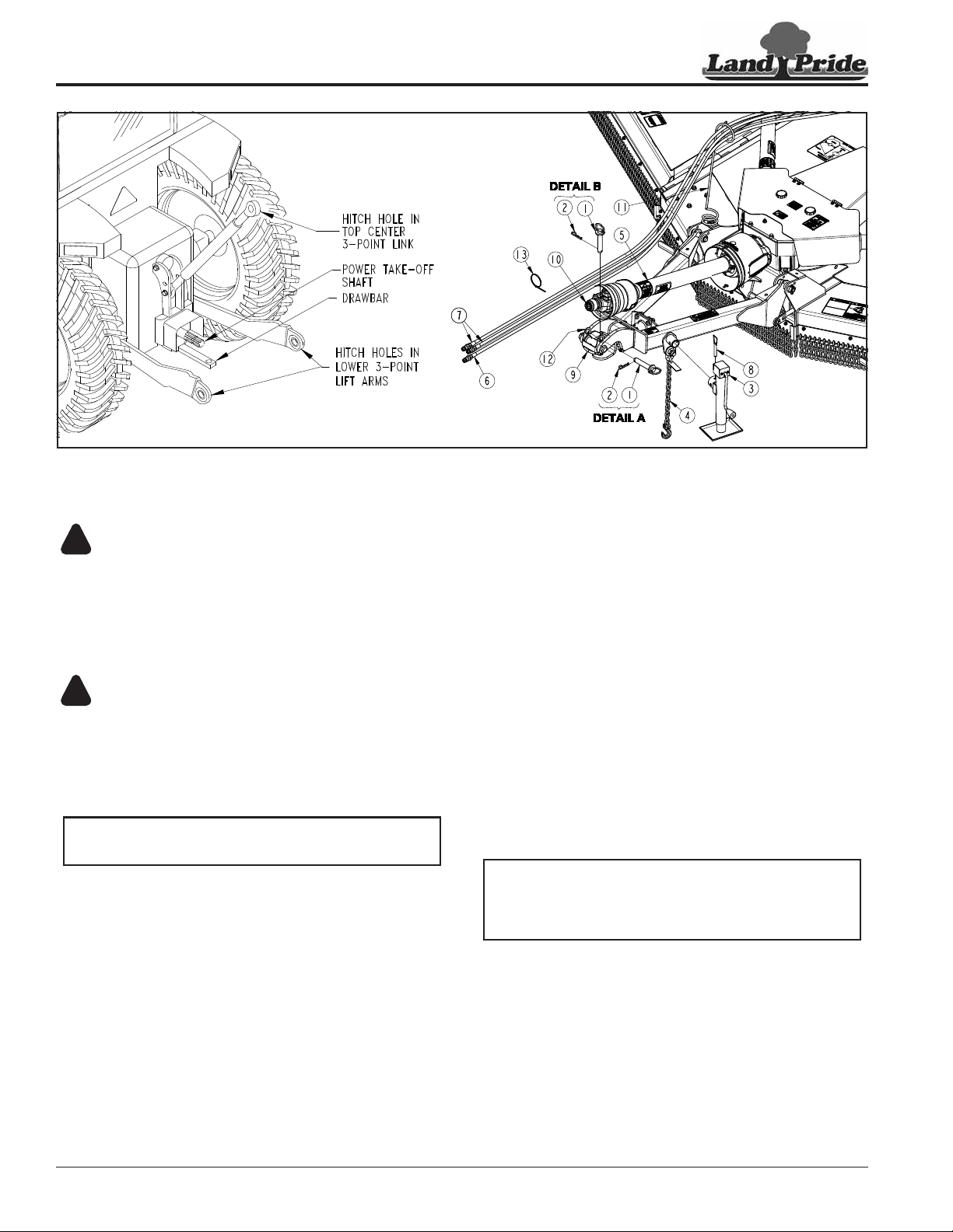
Table of Contents
Section 1: Assembly & Set-up
LP Performance Hitch Hook-up
Figure 1-12
LP Performance Hitch Hook-up
!
DANGER
To avoid serious injury or death:
A crushing hazard exists while hooking-up and unhooking
implement. Keep people and animals away while backing-up
to implement or pulling away from implement. Do not operate
hydraulic controls while a person or animal is dir ectly behind
the power machine or near the implement.
!
WARNING
To avoid serious injury or death:
The ball detent pin must be fully inserted into the park jack
with ball visible and popped out on the far side of the jack
before working on or around an unhooked cutter.
Refer to Figure 1-12:
NOTE: Hitch pin (#1) and hairpin cotter (#2) are
customer-supplied.
1. Make certain park jack (#3) is properly attached to
cutter hitch and secured with ball detent pin (#8).
2. If clevis hitch (#9) is not already supported
horizontal, rotate clevis horizontal and flip hitch
holder (#12) up so that its holes are on top as shown.
3. Insert customer-supplied hitch pin (#1) through holes
in hitch holder (#12) as shown in detail A. Secure with
hairpin cotter (#2).
4. Store center 3-point link in its storage hook.
5. Start tractor, raise 3-point arms fully up, and carefully
back tractor within close proximity of clevis (#9).
6. Shut tractor down properly before dismounting. Refer
to “Tractor Shutdown Procedure” on page 17.
3799837298
7. Verify tractor drawbar is adjusted correctly. Refer to
“Drawbar Set-up” dimensions on page 13.
8. Raise or lower park jack (#3) to align clevis (#9) with
tractor drawbar. Drawbar should fit between lower
and upper plates of clevis.
9. Restart tractor and continue to back tractor up to
cutter hitch until hitch holes in tractor drawbar and
hitch clevis (#9) are aligned.
10. Shut tractor down properly before dismounting.
11. Remove bushings in clevis if customer supplied hitch
pin diameter is larger than 1". See “LP Performance
Hitch Pin Diameter” on page 28 for instructions.
12. Remove hairpin cotter (2) and hitch pin (#1) from
hitch holder (#12) and rotate hitch holder down.
13. Attach cutter to tractor drawbar with hitch pin (#1) and
hairpin cotter (#2) as shown in detail B.
14. Lower park jack (#3) until cutter hitch weight is
supported by tractor drawbar.
IMPORTANT: Protect park jack by storing it on the
left wing deck before moving the cutter. Make sure
jack is stored with its base level or lower than the
head to prevent water and freeze damage.
15. Remove park jack (#3) from hitch and attach it to the
left-hand wing storage base with ball detent pin (#8).
Make sure base is level with or lower than the head
especially after the wings are folded up. See cover
picture for correct positioning.
16. Attach hitch safety chain (#4) to the tractor. Adjust
chain length to remove all slack except what is
necessary to permit turning. Lock chain hook
securely to the safety chain.
17. Continue with “Driveline Hook-up” on page 20.
18
RC3620 & RCM3620 Rotary Cuters 330-841M 9/25/18
Page 23
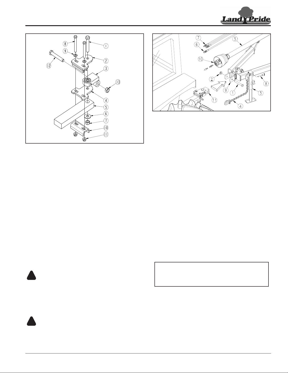
Table of Contents
Section 1: Assembly & Set-up
22265
Bar-Tite Hitch Assembly to Tractor Tongue
Figure 1-13
Bar-Tite Hitch Hook-up
Attach Bar-Tite Hitch to Tractor Drawbar
Refer to Figure 1-13:
1. Insert 1" x 5 1/2" hex bolt (#1) through hitch top
plate (#2), hitch bushing (#3), hitch wear plate (#4),
tractor drawbar (#5), and washer (#6) as shown.
Secure with 1" locknut (#7). Tighten 1" locknut snugly
to remove all play and then back nut
one-quarter turn. Do Not torque 1" locknut.
2. Insert two 3/4" x 6" GR5 hex bolts (#8) through,
3/4" flat washers (#9), hitch top plate (#2), hitch wear
plate (#4), and formed hitch support (#10) as shown.
Secure with 3/4" locknuts (#11).
3. Tighten 3/4" locknuts to correct torque.
4. Remove 1" x 6 1/2" GR5 hex bolt (#12) and 1" lock
nut (#13) from hitch bushing (#3). Keep bolt and
locknut for reuse.
Attach Bar-Tite Hitch to Rotary Cutter
!
DANGER
To avoid serious injury or death:
A crushing hazard exists while hooking-up and unhooking
implement. Keep people and animals away while backing-up
to implement or pulling away from implement. Do not operate
hydraulic controls while a person or animal is dir ectly behind
the power machine or near the implement.
!
WARNING
To avoid serious injury or death:
The ball detent pin must be fully inserted into the park jack
with ball visible and popped out on the far side of the jack
before working on or around an unhooked cutter.
33870
Bar-Tite Hitch Hook-up
Figure 1-14
Refer to Figure 1-14:
1. Make certain park jack (#3) is properly attached to
cutter and secured with ball detent pin (#8).
2. Store center 3-point link in the tractor’s storage hook.
3. Start tractor, raise 3-point arms fully up, and carefully
back tractor within close proximity of clevis (#9).
4. Shut tractor down properly before dismounting. Refer
to “Tractor Shutdown Procedure” on page 17.
5. Verify tractor drawbar is adjusted correctly. Refer to
“Drawbar Set-up” dimensions on page 13.
6. Raise or lower park jack (#3) to align hitch (#11) with
bolt hole in swivel clevis (#9).
7. Restart tractor and continue to back tractor up to
cutter hitch until hole in hitch bushing (#11) aligns
with holes in swivel clevis (#9).
8. Shut tractor down properly before dismounting.
9. Insert 1" x 6 1/2" GR5 hex bolt (#1) through swivel
clevis (#9) and hitch bushing (#11). Secure hex bolt
with locknut (#2). Tighten locknut snugly to remove
all play. Do Not torque 1" locknut.
10. Lower park jack (#3) until cutter hitch weight is
supported by tractor drawbar.
IMPORTANT: Protect park jack by storing it on the
left wing deck before moving the cutter. Make sure
jack is stored with its base level or lower than the
head to prevent water and freeze damage.
11. Remove park jack (#3) from hitch frame and attach it
to the left-hand wing storage base with ball detent
pin (#8). Make sure base is level with or lower than
the head especially after the wings are folded up. See
cover picture for correct positioning.
12. Attach hitch safety chain (#4) to tractor. Adjust chain
length to remove all slack except what is necessary
to permit turning. Securely lock chain hook to the
safety chain.
13. Continue with “Driveline Hook-up” on page 20.
RC3620 & RCM3620 Rotary Cuters 330-841M9/25/18
19
Page 24
Section 1: Assembly & Set-up
Table of Contents
Driveline Hook-up
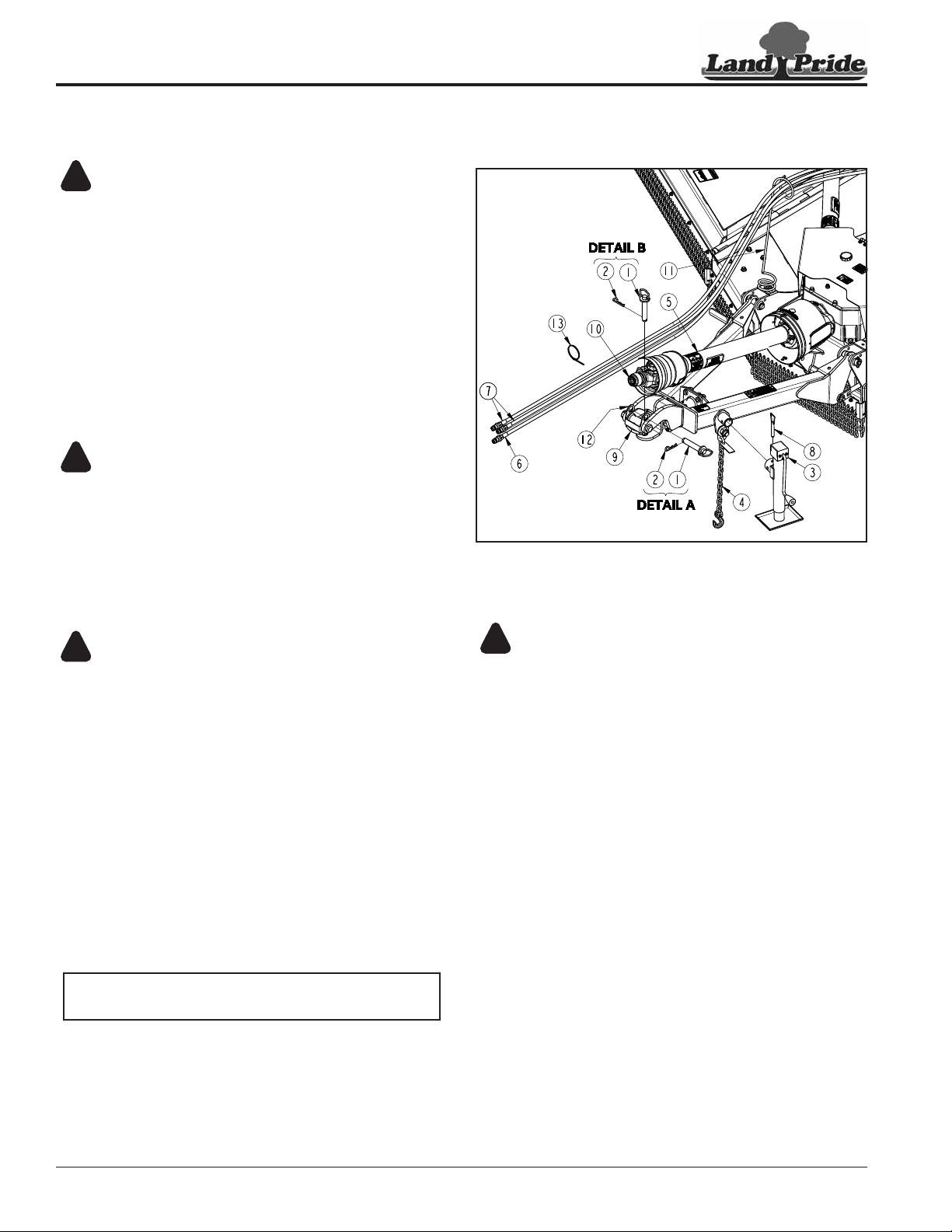
Refer to Figure 1-15:\
!
DANGER
To avoid serious injury or death:
• Do not engage power take-off while hooking-up or
unhooking the driveline, or while someone is standing near
the driveline. A person’s body and/or clothing can become
entangled in the driveline.
• Tractor power take-off shaft shield, driveline shields, and
gearbox shaft shields must be installed and in good working
condition to avoid driveline entanglement and projectiles
flying off of the driveline.
• Make certain driveline yokes are securely fastened at each
end. A loose yoke can work free allowing the driveline to
rotate uncontrollably causing implement damage and
bodily injury or death to anyone nearby.
!
WARNING
To avoid serious injury or death:
• Do not use a power take-off adapter. The adapter will
increase strain on the tractor’s power take-off shaft causing
possible damage to shaft and driveline. It will also defeat
the purpose of the tractor’s power take-off shield.
• Always shut tractor down using “Tractor Shutdown
Procedure” provided in this manual before dismounting
tractor.
6. If attached to cutter hitch, remove park jack (#3) and
stored on weight box. For detailed instructions, refer
to steps 10-11 on page 19.
37998
Hydraulic Hook-up
Figure 1-15
Hydraulic Hook-up
!
CAUTION
To avoid minor or moderate injury: Some tractors are
equipped with two power take-off speeds. Be certain your
tractor’s power take-off is set at the implement’s rated power
take-off speed or equipment breakage may result. RC models
are rated for 540 rpm and RCM models are rated for 1000
rpm.
1. If needed, collapse driveline (#5) by pushing tractor
end of driveline against splitter gearbox.
2. Pull back on yoke locking collar (#10) and slide yoke
over tractor power take-off shaft. (tractor power takeoff shaft shown in Figure 1-12 on page 18.)
3. Release locking collar (#10) and continue to push
outer yoke onto tractor power take-off shaft until
locking collar snaps in place.
4. Driveline (#5) should be moved back and forth to
ensure both ends are secured. Reattach loose ends.
IMPORTANT: The shields on the constant velocity
driveline with overrunning clutch must not rotate.
5. If main driveline is constant velocity with overrunning
clutch, attach safety chain on the inner shield to the
cutter and safety chain on the outer shield to the
tractor. Check safety chains to make sure they are
attached to the inner and outer driveline shields.
!
WARNING
To avoid serious injury or death:
Hydraulic fluid under high pressure can penetrate the skin
and/or eyes causing a serious injury. Wear protective gloves
and safety glasses or goggles when working with hydraulic
systems. Use a piece of cardboar d or wood rather than hands
when searching for leaks. A doctor familiar with this type of
injury must treat the injury within a few hours or gangrene
may result. DO NOT DELAY.
Refer to Figure 1-15:
1. Route wing folding cylinder hose (#6) through hose
support loops 19and connect to a remote outlet with
float option if available.
2. Route rephasing lift cylinder hose (#7) through hose
support loops (#11) and connect to a tractor duplex
outlet.
3. Secure hydraulic hoses together with zip ties (#13)
as needed to keep hoses from pinch areas caused by
raising and lowering the deck, folding the wings, and
making turns with the tractor.
20
RC3620 & RCM3620 Rotary Cuters 330-841M 9/25/18
Page 25
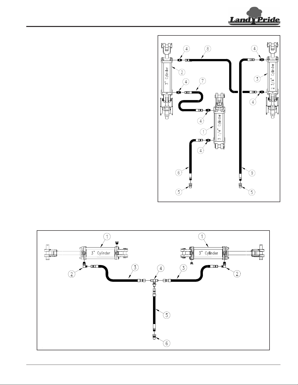
Table of Contents
Section 1: Assembly & Set-up
Rephasing Lift Cylinders & Plumbing
Refer to Figure 1-16:
The deck cutting height and transporting height are
controlled by three rephasing cylinders (#1, #2 & #3)
which are plumbed together to operate in unison. The
decks will not lift properly if rephasing cylinders are
plumbed incorrectly. Use Figure 1-16 to verify plumbing.
1. Rephasing hydraulic cylinder 3 1/4" x 8" x 1 1/4" rod
2. Rephasing hydraulic cylinder 3" x 8" x 1 1/4" rod
3. Rephasing hydraulic cylinder 2 3/4" x 8" x 1 1/4" rod
4. Straight adapter 3/4 MORB x 3/4MJIC
5. Quick disconnect poppet type coupler, 3/4" FORB male
6. 3/8" Hydraulic hose, 228" long x 3/4" MORB x 3/4" FJIC
7. 3/8" Hydraulic hose, 114" long x 3/4" FJIC
8. 3/8" Hydraulic hose, 234" long x 3/4" FJIC
9. 3/8" Hydraulic hose, 288" long x 3/4" MORB x 3/4" FJIC
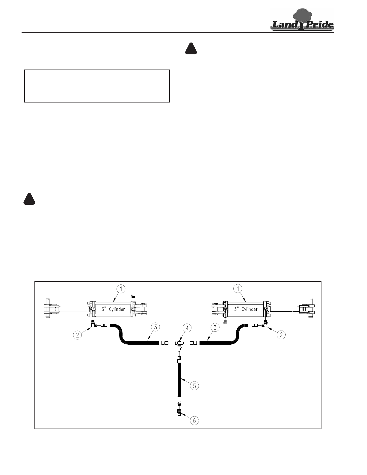
Folding Cylinders & Plumbing
Refer to Figure 1-17:
The wing folding cylinders (#1) are single-acting and
should be connected to an outlet with float option to allow
the wings to flex up and down as they travel over uneven
ground while cutting. Use Figure 1-17 to verify plumbing.
1. Hydraulic cylinders 3" x 12" x 1 1/4" rod
2. Orifice elbow, 1/16" x 9/16" MJIC x 9/16" MORB
3. 1/4" Hydraulic hose, 66" long x 9/16" FJIC x 9/16" FJIC
4. Bulkhead Tee 9/16"MJIC x 9/16"MJIC x 9/16"MJIC
5. 3/8" Hydraulic hose, 189" long x 3/4"MORB x 9/16" FJIC
6. Quick disconnect poppet type coupler, 3/4" FORB male
33912
Rephasing Lift Cylinders and Plumbing
Figure 1-16
Wing Folding Cylinders and Plumbing
Figure 1-17
RC3620 & RCM3620 Rotary Cuters 330-841M9/25/18
33913
21
Page 26
Section 1: Assembly & Set-up
Table of Contents
35266
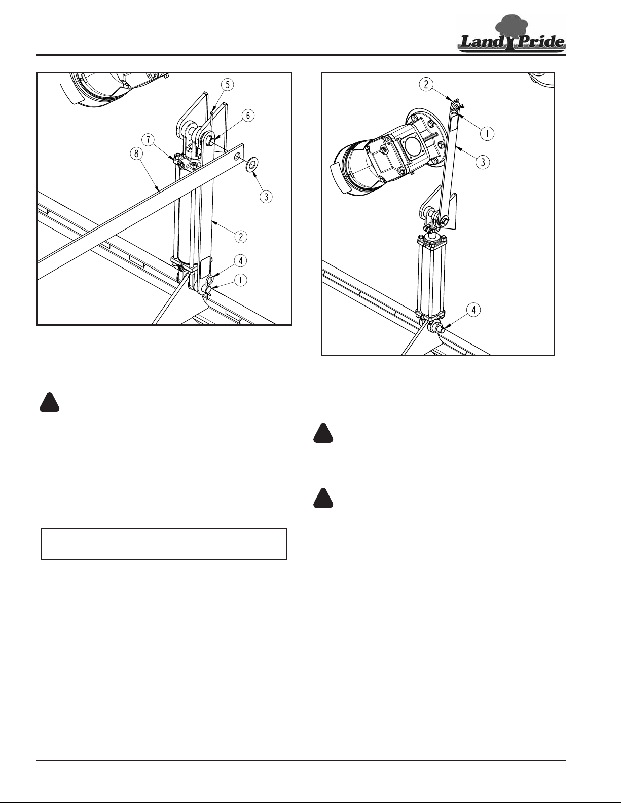
Remove Shipping Bar With Transport Locks Set
Figure 1-18
Remove Shipping Crossbar
Refer to Figure 1-18:
!
WARNING
To avoid serious injury or death:
• Metal shipping bands are under tension. Always wear eye
protection when cutting bands. Keep head, body, and body
extremities away from the area where the band will recoil
into when cut.
• Make sure transport locks ar e set before r emoving shipping
bar. Stay clear of wings while removing shipping bar. Once
shipping bar is removed, the wings will fall suddenly until
caught by transport locks.
NOTE: A come-along may be needed to pull wings
together before shipping bar (#8) can be removed.
1. Make sure cutter is parked on a level surface with
room on both sides for wings to unfold into. Place
gear selector in park, fully retract wing folding
cylinders (#7), shut tractor off, set park brake, and
remove switch key.
2. Verify transport lock bars (#2) are rotated down and
secured to cylinder pin (#1) with hairpin cotter (#4).
3. Cut & remove shipping bands between wing wheels.
4. Remove cotter pin (#5), flat washer (#3), and
shipping bar (#8) from cylinder pin (#6).
5. Replace flat washer (#3) and cotter pin (#5). Bend
one or more legs of cotter pin to secure it in place.
6. Repeat steps 4 & 5 for the other wing.
33868
Transport Bar in Storage Position
Figure 1-19
Unfold Wings
Refer to Figure 1-19:
!
DANGER
To avoid serious injury or death:
Keep everyone out of the area wher e the wing deck will unfold.
The wing deck can fall suddenly.
!
WARNING
To avoid serious injury or death:
W atch hydraulic hoses as the wings lower to be sur e they don’t
catch causing hoses to stretch and pull loose from the
hydraulic cylinders.
1. Make sure shipping crossbar is removed and all
safety alerts are followed as instructed above.
2. Rotate right transport lock bar (#3) up to storage
bracket (#2). Secure with existing hairpin (#1).
3. Repeat step 2 for left transport lock bar (#3).
4. Start tractor and lower wings down to the ground.
5. Set tractor control lever for wing cylinders in float
position.
6. Cycle wing folding cylinders back and forth several
times to purge them. For additional details, see
“Purge Hydraulic System” on page 24.
22
RC3620 & RCM3620 Rotary Cuters 330-841M 9/25/18
Page 27
Section 1: Assembly & Set-up
Table of Contents
35222
Wing Set-up for Shipping
Figure 1-20
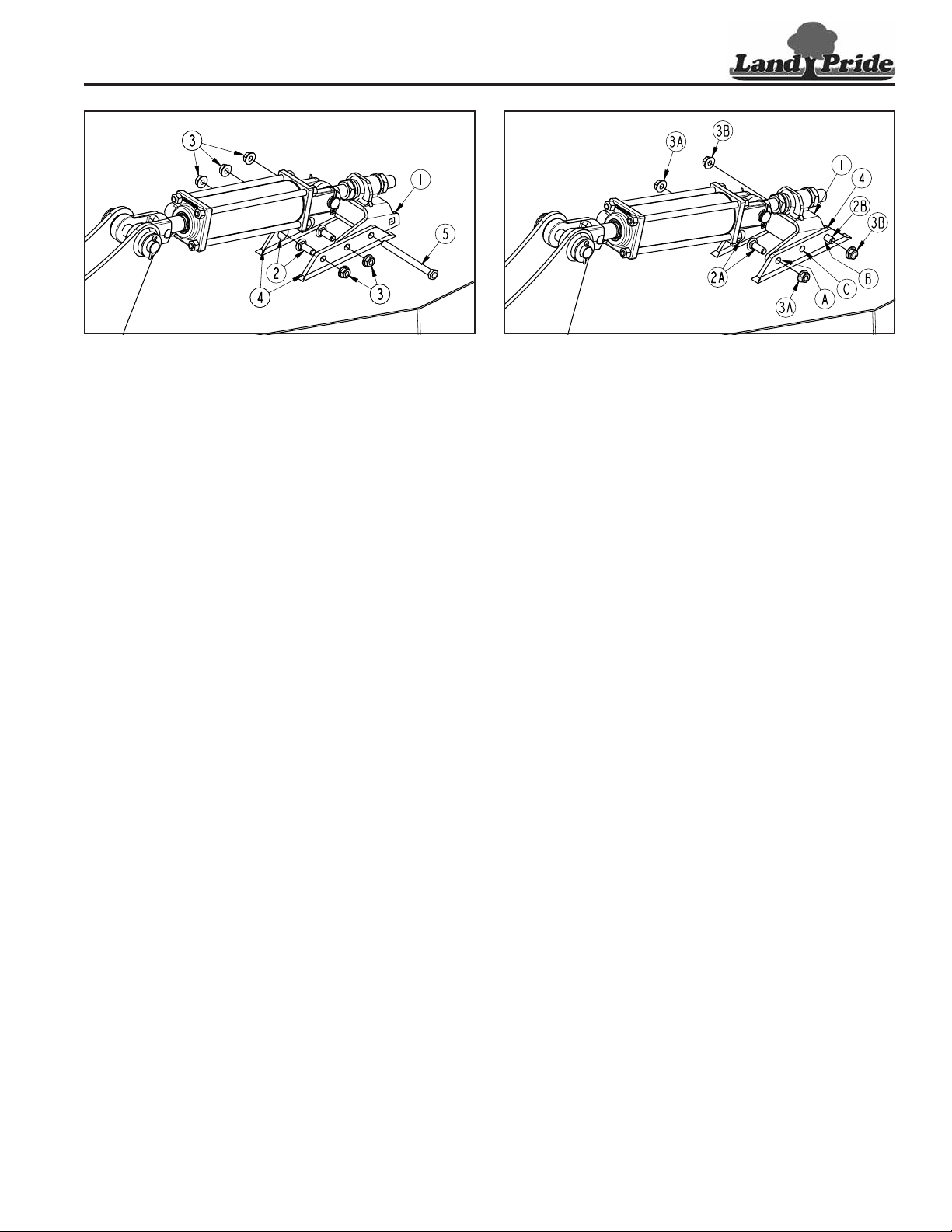
Relocate Wing Lift Cylinder Mounts
Refer to Figure 1-20:
The rephasing lift cylinders are shipped from the factory
moved forward 2 1/2". Mounting brackets (#1) must be
relocated 2 1/2" rearward on both wings as follows:
1. With wings unfolded, lower cutter down until right
wing is resting on its skid shoe and transport
wheel(s). If needed, place a support block under the
wing skid shoe to ensure right wing is resting on its
skid shoe and transport wheels.
2. Shut tractor down properly before dismounting. Refer
to “Tractor Shutdown Procedure” on page 17.
3. Move tractor hydraulic deck lift control lever back and
forth several times to relieve all hydraulic pressure in
the deck lift hydraulic system.
4. At the right-hand wing, remove all five whiz nuts (#3),
cap screw (#5) and four carriage bolts (#2). Keep
carriage bolts and four hex whiz nuts (#3) for reuse.
Discard cap screw (#5) and one hex whiz nut (#3).
5. Remove mounting bracket (#1) from between
mounting ears (#4).
6. Using tractor control lever, fold wing deck up high
enough to place a support block under its skid shoe.
Use a 4" support block if cutter is equipped with
21" laminated tires and a 6" support block if cutter is
equipped with 29" aircraft tires.
7. Unfold wing deck until its skid shoe is resting on the
4" or 6" support block.
35223
Wing Set-up for Field Use
Figure 1-21
Refer to Figure 1-21:
8. Extend or retract hydraulic lift cylinder on the wing
until rear holes “A” in mounting bracket (#1) are slight
back of holes “A” in mounting ears (#4).
9. Attach a hoist or jack under the right-hand wing
wheel axle and raise wheels up until carriage bolts
(#2A) can be inserted. If needed, use a drift punch to
align rear holes “A”.
10. Insert rear carriage bolts (#2A) as shown and install
hex whiz nuts (#3A). Draw nuts up snug, do not
tighten at this time.
11. Use a drift punch in holes “C” to align the front
holes “B”.
12. Insert front carriage bolts (#2B) in holes “B” as
shown and install hex whiz nuts (#3B).
13. Tighten hex whiz nuts (#3A & #3B) to the correct
torque.
14. Remove hoist or jack from under the transport
wheels.
15. Fold wing up, remove support block from under its
skid shoe, and return wing to its unfolded position.
16. Repeat steps 1-15 for the left wing.
RC3620 & RCM3620 Rotary Cuters 330-841M9/25/18
23
Page 28
Section 1: Assembly & Set-up
Table of Contents
Driveline Clearance Check
Check driveline for adequate clearance under all ranges
of cutter height.
NOTE: The lift cylinders should raise the cutter up
while pushing the control lever forward and lower
while pulling the lever back. Switch connections at
the duplex outlet if lift control lever works opposite.
1. With driveline attached to the tractor, slowly raise and
lower cutter to its upper and lower limits while
observing clearances between hitch and driveline.
2. Adjust tractor drawbar height and length if driveline
interferes. See “Drawbar Set-up” on page 13 for
correct placement of tractor drawbar.
3. Cycle hydraulic lift system several times to purge
hydraulic lift system of trapped air. See “Purge
Hydraulic System” on this page.
Purge Hydraulic System
Refer to Figure 1-22:
!
DANGER
To avoid serious injury or death:
Never remove or install a folding wing cylinder with cylinder
rod r etracted and wing folded up. The wing is unstable without
its folding cylinder and can suddenly fall. Also, air trapped in
a new or repaired cylinder will drop the wing suddenly when
lowering the wing. Either situation can render the cutter
inoperable and cause serious bodily injury or death.
!
WARNING
To avoid serious injury or death:
Be sure center and wing decks are lowered to the ground and
all hydraulic pressure is relieved before disconnecting any
hydraulic lines or fittings to purge the hydraulic system.
Be sure tractor reservoir is filled properly before
operating hydraulic cylinders. If tractor reservoir is low on
hydraulic fluid, there is a chance of drawing air into the
system causing jerky or uneven cylinder movements.
The wing deck lift cylinder may be purged as follows:
1. With wings lowered to the ground, shut tractor off and
move hydraulic control lever for the wings back and
forth to relieve all hydraulic pressure.
2. Loosen hydraulic hoses (#3) slightly at each wing
cylinder elbow (#2) to allow air and fluid to escape.
3. Restart tractor. Slowly activate tractor control lever to
retract wing cylinders and to purge trapped air.
4. Once air is purged from the hydraulic system for the
wing cylinders, tighten hydraulic hose fittings. at
elbows (#2).
Wing Folding Cylinders
Figure 1-22
24
RC3620 & RCM3620 Rotary Cuters 330-841M 9/25/18
33913
Page 29
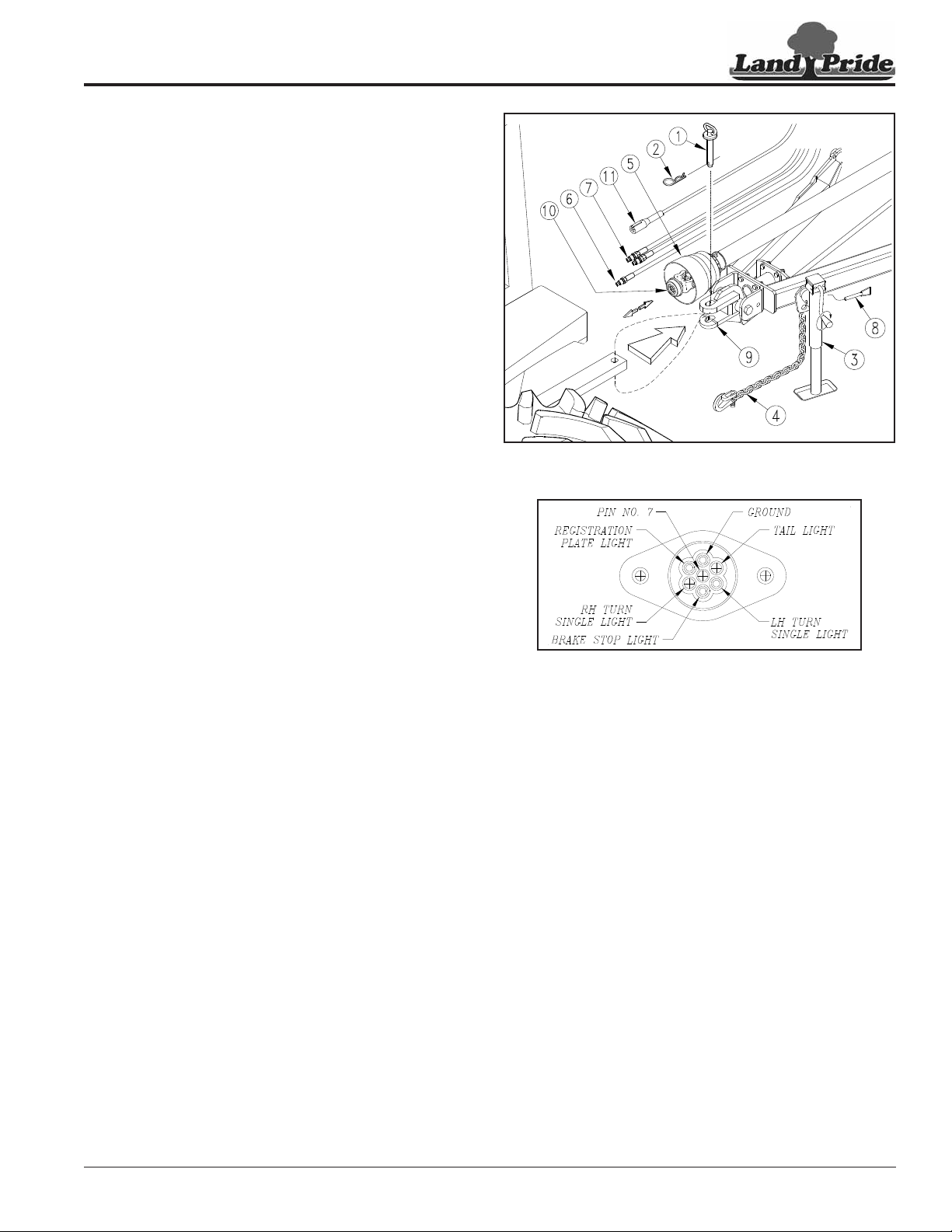
Table of Contents
Section 1: Assembly & Set-up
Hook-up LED Lights
Refer to Figure 1-23:
The lead wiring harness (#11) is equipped with a 7-way
round pin connector for connecting to the tractor’s 7-pin
electrical outlet shown in Figure 1-24.
1. Route lead wire harness (#11) through spring hose
loop (not shown).
2. Connect lead wire harness (#11) to the tractor’s
7-way round pin receiver.
3. It is best to have a second person verify the lights are
operating. Start tractor and operate lights as follows:
a. Turn on head lights to verify red lights illuminate.
b. Turn on flasher lights to verify amber light are
blinking on and off.
4. If the lights did not operate properly, recheck hook-up
of enhance module and wire harnesses. Make
necessary changes and repeat step 3 above.
5. Check wire harness routing to make sure wires will
not be pinched as wing decks are folded and
unfolded and while raising and lowering cutter height.
6. Add cable ties (not shown) to wire harness (#11) as
needed to secure the harnesses in place.
33861
LED Hookup (Standard Clevis Hitch Shown)
Figure 1-23
Tractor 7-Pin Electrical Outlet
Figure 1-24
RC3620 & RCM3620 Rotary Cuters 330-841M9/25/18
25
Page 30
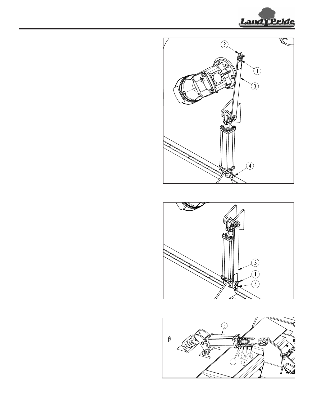
Table of Contents
Section 1: Assembly & Set-up
Unhook Rotary Cutter
1. See “Long-Term Storage” on page 46 if parking
cutter for long periods and end of season.
2. If power take-off is engaged, reduce tractor engine
speed to an idle and then disengage power take-off.
3. Park cutter on a level, hard surface. Place tractor
gear selector in park or set park brake.
Refer to Figure 1-25:
4. Wait for blades to come to a complete stop and then
fold wings up to transport position.
5. Shut tractor engine off and remove switch key before
dismounting from tractor.
6. Remove hairpin cotter (#1) from storage tab (#2).
Refer to Figure 1-26:
7. Swing transport lock bars (#3) down and place over
lock pins (#4). Secure with hairpin cotters (#1).
Refer to Figure 1-27:
8. Spread stroke control spacers (#1, #2, #3 & #4) apart
at the break line and remove all of them from
hydraulic cylinder (#1).
9. Start tractor and lower cutter until front skids are
resting on the ground or on support blocks.
10. Without changing deck lift height, shut tractor down
properly before dismounting. Refer to “Tractor
Shutdown Procedure” on page 17.
11. Replace stroke control spacers (#1, #2, #3 & #4) as
needed to support wheels at this position.
12. With no one around or near the cutter, move cylinder
deck and wing cylinder lift levers back and forth to
release all hydraulic pressure at the couplers.
33868
Transport Bar, Storage Position
Figure 1-25
33867
Transport Bar, Locked Position
Figure 1-26
33866
Hydraulic Lift Cylinder With Stroke Control Spacers
Figure 1-27
26
RC3620 & RCM3620 Rotary Cuters 330-841M 9/25/18
Page 31
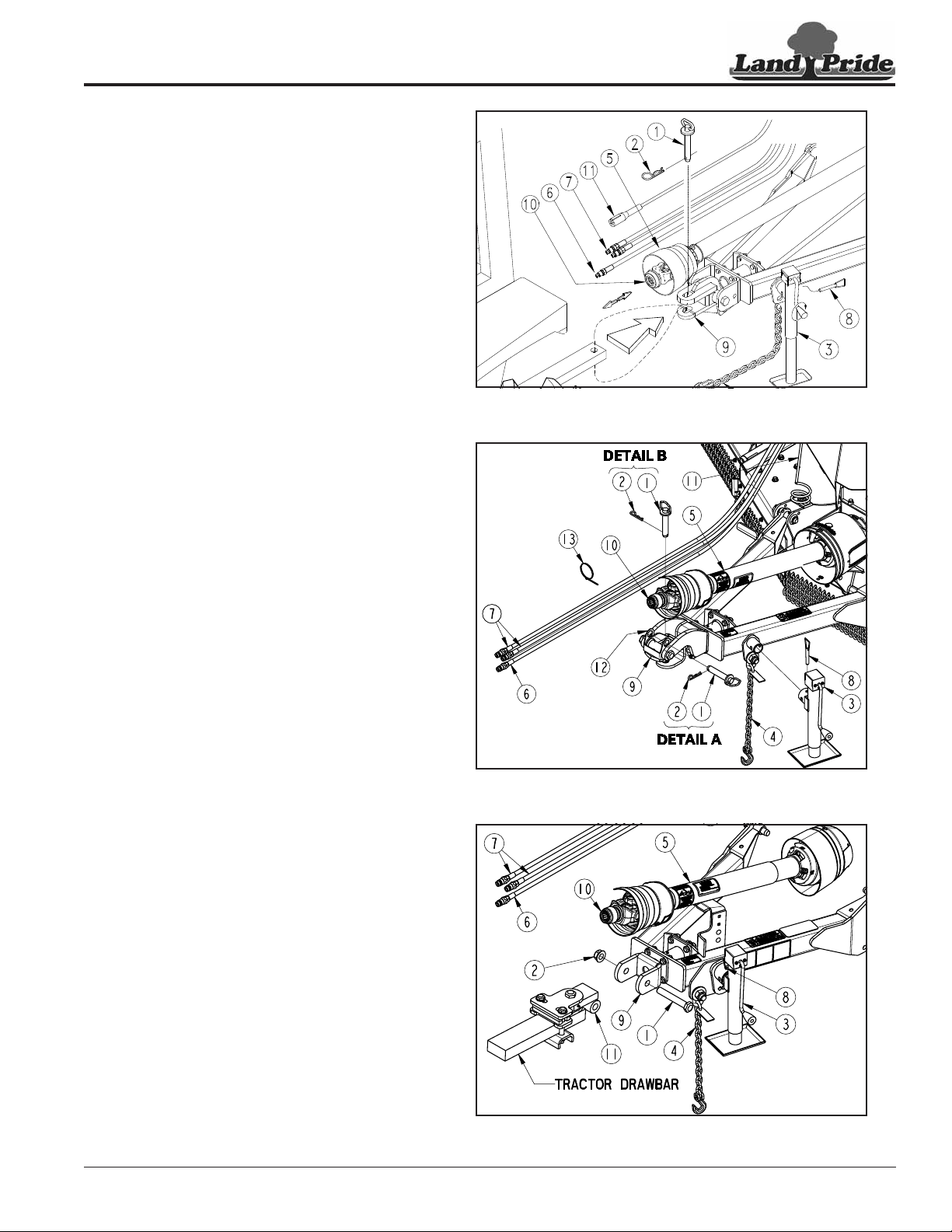
Section 1: Assembly & Set-up
Table of Contents
Refer to Figure 1-28:
13. Remove parking jack (#3) from left-hand wing deck
and attach to the cutter hitch. Secure parking jack in
place with ball detent pin (#8).
14. Unhook hydraulic hoses (#6 & #7) from tractor duplex
outlet. Insert couplers through spring hose loop to
keep couplers out of the dirt.
15. Unhook wire harness (#11) from tractor outlet. Coil
wire harness and store over spring hose loop with
connector hanging down to keep moisture out.
16. Unhook hitch safety chain (#4) from tractor.
17. Pull back on locking collar (#10) and pull
driveline (#5) from tractor power take-off shaft.
18. Collapse driveline (#5) by pushing tractor end of
driveline toward the splitter gearbox.
19. Adjust park jack (#3) to raise cutter up until all load is
removed from tractor drawbar.
20. Remove connecting hitch pin or bolt as follows:
a. For Standard Clevis Hitch, See Figure 1-28:
Remove hairpin cotter (#2) and hitch pin (#1).
a. For LP Performance Hitch, See Detail B in
Figure 1-29:
Remove hairpin cotter (#2) and hitch pin (#1).
b. For Bar-Tite Hitch, See Figure 1-30: Remove
locknut (#2) and bolt (#1).
21. Restart tractor and drive tractor slowly forward
several feet.
22. Shut tractor down properly before dismounting.
23. Lower park jack (#3) until cutter is resting on its front
skid shoes.
24. Replace connecting pin/bolt (#1) as follows:
a. For Standard Clevis Hitch, See Figure 1-28:
If unhooking standard clevis, replace connecting
pin (#1) in clevis (#9). Secure hitch pin with
hairpin cotter (#2).
b. For LP Performance Hitch, See Detail A in
Figure 1-29:
Rotate clevis (#9) horizontal and flip hitch holder
(#12) up so that its holes are on top as shown.
Insert customer-supplied hitch pin (#1) through
holes in hitch holder (#12). Secure with hairpin
cotter (#2).
c. For Bar-Tite Hitch, See Figure 1-30:
If unhooking bar-tite hitch, remove hitch (#11) from
tractor drawbar and reattach it to the hitch (#9)
with removed bolt (#1) and locknut (#2) Screw
locknut on 4 or 5 full turns. Do not torque nut tight.
33861
Tractor Unhooking from Standard Clevis Hitch
Figure 1-28
37998
Unhook Tractor From Bar-Tite Hitch
Figure 1-29
Unhook Tractor From Bar-Tite Hitch
Figure 1-30
RC3620 & RCM3620 Rotary Cuters 330-841M9/25/18
33870
27
Page 32
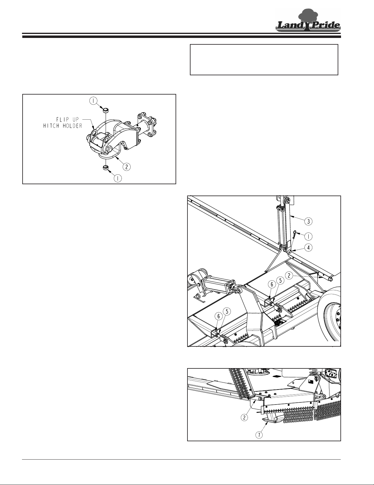
Table of Contents
Section 2: Adjustments
Section 2: Adjustments
LP Performance Hitch Pin Diameter
Refer to Figure 2-1:
The LP Performance Hitch is designed to receive
1" diameter hitch pins. To convert the hitch to receive
1 1/4" diameter hitch pins, knock out upper and lower
bushings (#1) in clevis (#2).
39093
LP Performance Hitch Hole Diameter
Figure 2-1
NOTE: Unscrewing coupler nuts (#6) will lengthen
leveling rods and lower front of cutter. Tightening
coupler nuts (#6) will shorten leveling rods and raise
front of cutter.
If continuous hinges are too high at the front:
a. Loosen jam nuts (#5).
b. Unscrew coupler nuts (#6) an equal amount to
lower front of cutter until both hinges are inclined
from front to back by 1" with the front being closer
to the ground than the back.
If continuous hinges are too low at the front:
a. Loosen jam nuts (#5) several turns.
b. Tighten coupler nuts (#6) an equal amount to
raise front of cutter until both hinges are inclined
from front to back by 1" with the front being closer
to the ground than the back.
9. Be sure the leveling rods have equal amounts of
tension and then re-tighten jam nuts (#5) against
coupler nuts (#6).
Level Cutter Decks
Make adjustments with cutter hooked to the tractor
operating it or to one with the same drawbar height.
Level Center Deck
Refer to Figure 2-2:
1. Attach cutter to tractor and park on level ground.
2. Raise both wings fully up with tractor hydraulics.
3. Shut tractor down properly before dismounting. Refer
to “Tractor Shutdown Procedure” on page 17.
4. Lock wings folded up with transport locks (#3) and
hairpin cotters (#1) as shown. See “Transport
Locks” on page 33 for detailed instructions.
Refer to Figure 2-3:
5. With tractor hydraulics, adjust center deck until front
skids (#7) are 2 to 3 inches above ground.
6. Without changing deck height, shut tractor down
properly before dismounting.
7. On both sides of the center deck are continuous
hinges (#2). Measure the height they are off the
ground as follows:
a. Refer to Figure 2-2: At back of cutter, measure
distance from bottom of right hinge (#2) to ground
and from bottom of left hinge to ground. These
two measurements should be equal.
b. Refer to Figure 2-3: At front of cutter, measure
distance from bottom of right hinge (#2) to ground
and from bottom of left hinge to ground. These two
measurements should be 1" less than the rear
measurements taken in step a.
Refer to Figure 2-2 on page 28:
8. Adjust length of leveling rods at coupler nuts (#6) if
continuous hinges are not 1" lower at the front:
39119
Center Deck Leveling Rods
Figure 2-2
33863
Front Skid Shoe Position
Figure 2-3
28
RC3620 & RCM3620 Rotary Cuters 330-841M 9/25/18
Page 33
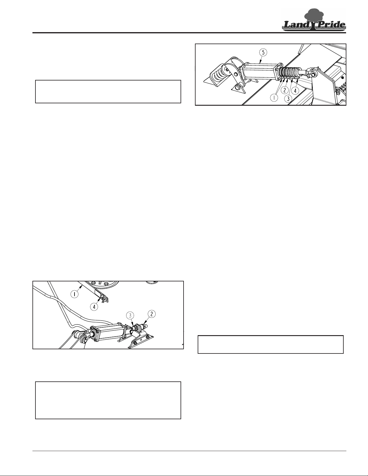
Table of Contents
Section 2: Adjustments
Level Wing Deck
Refer to Figure 2-4:
Each wing section will need adjusting if its top is not level
with top of center deck when wings are unfolded.
IMPORTANT: Make sure wing lift cylinder mounts
have been relocated for field use. See “Relocate
Wing Lift Cylinder Mounts” on page 23.
1. With tractor hydraulics, raise wings fully up, remove
transport locks (#1) from transport position to field
position as shown. Be sure to secure transport locks
with hairpin cotters (#4). See “Transport Locks” on
page 33 for detailed instructions.
2. Lower wings to ground position and pull cutter
straight forward six to ten feet to allow outer wing
wheels to properly align themselves.
3. With tractor hydraulics, fully extend all three
rephasing cylinders and then lower cutter to
approximate cutting height.
4. Check wing tops to see if they are level with top of
center deck. If outer edge of either wing is higher or
lower than the center deck, then that wing should be
leveled as follows:
a. If the outer wing edge is higher than the center
deck, loosen adjusting nut (#3) to lower the outer
wing edge until wing is level. Tighten adjusting
nut (#2) to the correct torque when level.
b. If the outer wing edge is lower than the center
deck, loosen adjusting nut (#2) several turns and
tighten adjusting nut (#3) until wing is level.
Tighten adjusting nut (#2) to the correct torque
when level.
33866
Set Deck Height With Stroke Control Spacers
Figure 2-5
2. Place tractor gear selector in park, set park brake,
shut off tractor, and remove key before dismounting
from tractor.
3. Remove all stroke control spacers (#1 to #4) from
center hydraulic cylinder (#5) by spreading them
apart at the break line. Store spacers in a location
they can be retrieved.
4. Start tractor and engage blades. See instructions for
“Engage Blades” on page 35.
5. Using tractor control lever, adjust cutter to the desired
cutting height and then travel forward for
approximately 20 to 50 feet.
6. Stop tractor, disengage power take-off, place tractor
gear selector in park, set park brake, shut off tractor,
remove key, and wait for blades to come to a
complete stop before dismounting from tractor.
7. Measure height of cut grass/material. This distance
is the cutting height. If this height is acceptable,
continue with step 8. If this height is unacceptable,
repeat steps 4-7 until desired cutting height is
achieved.
8. Select required size and number of stroke control
spacers (#1 to #4) that will fit on the center hydraulic
cylinder rod. The following spacers are available.
• (#1): Two 1" spacers
• (#2): One 1 1/4" spacer
• (#3): One 1 1/2" spacer
• (#4): One 1 3/4" spacer
33928
Leveling Wing Deck
Figure 2-4
Adjust Deck Cutting Height
NOTE: Make all cutting height adjustments in the
field using height of cut grass/material as a guide.
Do not measure blade height above ground as the
non-operating blade height will be different than the
operating blade height.
Refer to Figure 2-5:
1. At the cutting site, unfold wings and raise center deck
fully up with lift cylinder (#5). See instructions for
“Unfold Wings” on page 22.
NOTE: Removing spacers lowers cutting height and
adding spacers raises cutting height.
9. Return to the tractor and raise Rotary Cutter up
again. With tractor shut off and switch key removed,
install selected stroke control spacers on the center
hydraulic cylinder rod. Do not install spacers on the
wing rephasing cylinders.
10. Return to tractor and lower cutter against stroke
control spacers. Recheck cutting height in steps 4-7.
If needed, adjust size and quantity of stroke control
spacers until desired cutting height is achieved.
11. Keep remaining spacers with tractor for field
adjustments.
RC3620 & RCM3620 Rotary Cuters 330-841M9/25/18
29
Page 34
Table of Contents
Section 3: Operating Instructions
Section 3: Operating Instructions
Startup Checklist
Hazard control and accident prevention are dependent
upon the awareness, concern, prudence, and proper
training involved in the operation, transport, storage, and
maintenance of the Rotary Cutter. It is absolutely
essential that no one operates the cutter unless they are
age 16 or older and have read, fully understood, and are
totally familiar with the Operator’s Manual. Make sure the
operator has paid particular attention to:
Important Safety Information, page 1
• Section 1: Assembly & Set-up, page 13
• Section 2: Adjustments, page 28
• Section 3: Operating Instructions, page 30
• Section 4: Options & Accessories, page 37
• Section 5: Maintenance & Lubrication, page 39
Perform the following inspections before using your
Rotary Cutter.
Operating Checklist
Make sure all guards and shields are in place
and in good working condition.
Refer to “Important Safety Information”.
Follow hook-up and driveline installation
instructions.
Refer to “Section 1: Assembly & Set-up”.
Make all required adjustments.
Refer to “Section 2: Adjustments”.
Preform all required maintenance.
Refer to “Section 5: Maintenance & Lubrication”.
Lubricate cutter and drivelines as needed.
Refer to “Lubrication Points”.
Lubricate all gearboxes and replace oil plugs
properly. Refer to Gearbox lubrication.
Check cutter initially and periodically for loose
bolts and pins. Refer to “Torque Values Chart”.
Check Page
1
13
28
39
47
49
58
Safety Information
!
DANGER
To avoid serious injury or death:
• Do not walk, stand, or allow anyone else in the area wher e
a raised wing will fall unless the wing is securely locked in
the raised position with its transport lock.
• Rotary Cutters have the ability to discharge objects at high
speeds; therefor e, the use of front and r ear safety guar ds are
required with this cutter. Specifically, double row chain
guards should be used when cutting along r oadways and in
areas where people may be present. Stop blade rotation if
bystanders are in or around the area.
• Tractor power take-off shaft shield, driveline shields, and
gearbox shaft shields must be installed and in good working
condition to avoid driveline entanglement and projectiles
flying off of the driveline.
•
Always disconnect driveline from the tractor before
servicing the drivetrain and components powered by the
drivetrain. A person can become entangled in the drivetrain
if the tractor is started and the power take-off is engaged.
• Always secure equipment with solid, non-concr ete supports
before working under it. Never go under equipment
supported by concrete blocks or hydraulics. Concrete can
break, hydraulic lines can burst, and/or hydraulic controls
can be actuated even when power to hydraulics is off.
• Do not operate a broken or bent driveline. Such a driveline
will break apart while r otating at high speeds and can cause
serious injury or death. Always remove the implement from
use until the damaged driveline can be repair ed or replaced.
• Do not raise one or both wings up with power take-off
engaged or drivelines rotating. Objects can be thrown by
rotating blades. Always keep people away fr om a cutter that
is operating.
• Do not use cutter as a fan. Cutting blades are not properly
designed or guarded for this use.
• The cutter must be operated with both wings attached.
Removing one wing will increase risk of r ollover. Removing
one or both wings will expose blades. Blades rotating at
high speed will cut body extremities and throw objects.
• Do not engage power take-off while hooking-up or
unhooking the driveline, or while someone is standing near
the driveline. A person’s body and/or clothing can become
entangled in the driveline.
• Never place hands or feet under the deck or attempt to make
adjustments to the cutter with power take-off engaged.
Cutter blades rotating at high speeds cannot be seen and ar e
located close to the deck sides. Body extremities will be cut
off instantly.
• This cutter is equipped with free-swinging cutting blades to
reduce shock loads. However, it is best to avoid striking
solid objects for your safety and to protect the cutter from
damage.
• Keep everyone away from the cutter when folding or
unfolding the wings or when raising or lowering the cutter.
The cutter can pinch or crush a person when performing
these operations.
!
WARNING
To avoid serious injury or death:
• Allow only persons to operate this implement who have
fully read and comprehended this manual, who have been
properly trained in the safe operation of this implement, and
who are age 16 or older. Serious injury or death can result
from the inability to read, understand, and follow
instructions provided in this manual.
• Do not operate and/or travel across inclines wher e tractor
and/or implement can roll over. Consult your tractor’s
manual for acceptable inclines the tractor is capable of
traveling across.
30
RC3620 & RCM3620 Rotary Cuters 330-841M 9/25/18
Page 35
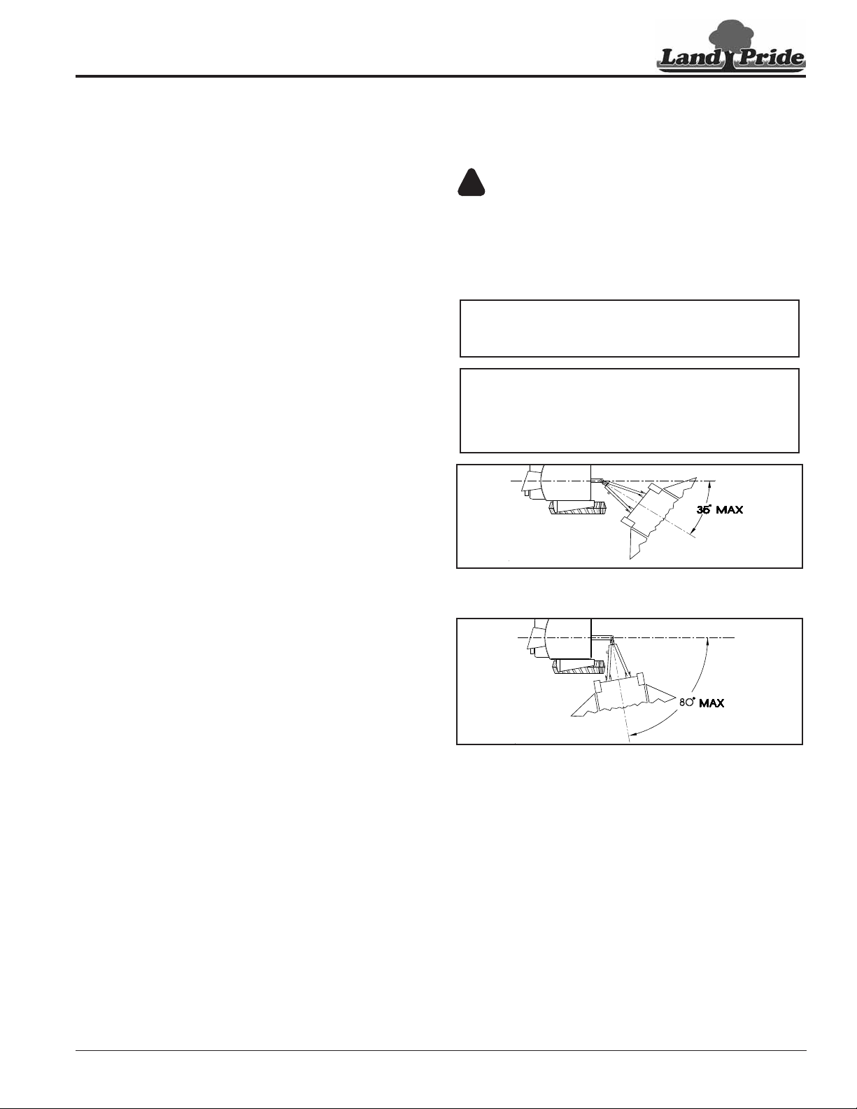
Section 3: Operating Instructions
Table of Contents
Perform scheduled maintenance. Check for loose
•
hardware, missing parts, broken parts, structural cracks,
and excessive wear. Make repairs befor e putting implement
back into service. Serious breakdowns can result in injury
or death.
• Never carry riders on the implement or tractor. Riders can
obstruct the operator’s view, interfere with control of the
equipment, be pinched by moving components, become
entangled in rotating components, be struck by objects, be
thrown or fall from the equipment, etc.
• Always shut tractor down using “Tractor Shutdown
Procedure” provided in this manual before dismounting
tractor.
• Do not raise the wing off the ground when mowing across
an incline. The weight of the wing will increase the risk of a
rollover.
• Operate only power machines equipped with a certified
Roll-Over Protective Structure (ROPS) and seat belt. Keep
folding ROPS in the “locked up” position when
appropriate. If ROPS is in the locked up position, fasten seat
belt snugly and securely to help protect against serious
injury or death from falling and machine overturn.
• Clear area to be cut of debris and other unforeseen
removable objects before cutting. Mark non-removable
hazards such as tr ee stumps, post stubs, pr otruding objects,
rocks, drop-offs, holes, etc. with a visible flag.
• Watch while making tight turns to ensure that the rear
tractor tires and lower 3-point arms do not make contact
with cutter hitch, driveline or deck. Keep lower 3-point
arms raised at all times when hitched to a pull-type cutter.
• W ait for blades to come to a complete stop befor e accessing
blade bolts through blade bolt access hole.
• Do not use implement to lift objects; to pull objects such as
fence posts, stumps, etc; or to push objects. The unit is not
designed or guarded for these uses.
• Do not use implement to tow other equipment unless it is
designed with a tow hitch. Doing so can result in loss of
control and damage the equipment.
• Do not operate a cutter with a hitch or hitch pin that is
excessively worn, bent, broken, or has structural cracks.
The hitch and/or hitch pin can break apart separating cutter
from tractor.
• Do not use a power take-off adapter. The adapter will
increase strain on the tractor’s power take-off shaft causing
possible damage to shaft and driveline. It will also defeat
the purpose of the tractor’s power take-off shield.
•
•
Avoid catching hydraulic hoses on brush, posts, tree limbs,
and other protrusions that could damage and/or br eak them.
• Buildup of debris around moving components and
gearboxes is a fire hazard. Keep rotating parts and
gearboxes free from debris to avoid serious injury and
property damage.
• Improper oil level can cause bearing failure and be a fire
hazard. Maintain proper gearbox oil level to avoid serious
injury and property damage.
• Do not exceed rated cutting capacity of your cutter. See
specifications & capacities for specified cutting capacity.
Exceeding rated cutting capacity can damage drive
components, cutter blades, and deck components.
!
CAUTION
To avoid minor or moderate injury: Some tractors are
equipped with two power take-off speeds. Be certain your
tractor’s power take-off is set at the implement’s rated power
take-off speed or equipment breakage may result. RC models
are rated for 540 rpm and RCM models are rated for 1000
rpm.
IMPORTANT: Maintain correct power take-off speed.
Loss of power take-off speed will allow blades to
swing back and result in ragged, uneven cutting.
IMPORTANT: If wing driveline profile is bent or
twisted, disconnect that driveline from the wing
gearbox before folding the wing up. This will protect
both the wing and divider gearbox. Repair driveline
before putting cutter back into service.
11934
Standard Conventional U-Joint Driveline
Figure 3-1
20795
Constant Velocity (CV) Driveline
Figure 3-2
Avoid Extreme Turning Angles
Refer to Figure 3-1 & Figure 3-2:
Plan your field cutting to minimize number of turns,
especially extreme turning angles. Avoid tractor-to-cutter
turning angles that exceeds driveline maximum turning
angle. If the turn cannot be avoided, disengage tractor
power take-off and wait for the driveline to stop rotating
before making the turn.
• Standard Conventional Driveline:
Maximum turning angle = 35o.
• Constant Velocity Driveline:
Maximum turning angle = 80o.
RC3620 & RCM3620 Rotary Cuters 330-841M9/25/18
31
Page 36

Section 3: Operating Instructions
Table of Contents
Tractor & Cutter Inspection
Make the following inspections with cutter attached to a
tractor and cutter parked on a level surface, power takeoff disengaged, and cutter blades stopped.
1. Inspect tractor safety equipment to make sure it is in
good working condition.
2. Inspect cutter safety equipment to make sure it is
installed and in good working condition.
3. Check driveline to make certain it is securely
connected to the tractor power take-off shaft and
cutter gearbox shaft. Also, make certain that the
guards are in good working condition and in place.
4. Check driveline hanger. Make sure it is rotated down
away from the driveline.
5. Remove 3-point lower arms or secure them in the
raised position so they do not interfere with driveline,
hoses, or hitch.
6. Check all hoses and wires to be sure that they will not
pinch or come in contact with the folding wing and
rotating drivelines.
7. Start tractor and carefully raise and lower implement
to ensure tractor drawbar, tires, and other equipment
on the tractor do not contact cutter or driveline.
8. Raise center deck fully up.
9. Without lowering cutter, shut tractor down properly
before dismounting. Refer to “Tractor Shutdown
Procedure” on page 17.
10. Place sturdy support blocks or jack stands under the
four center deck corners.
11. Start tractor and lower center deck down onto the
supports.
12. Shut tractor down properly before dismounting. Refer
to “Tractor Shutdown Procedure” on page 17.
13. With cutter resting on solid supports, power take-off
disengaged, and blade rotation completely stopped:
• Check for and remove foreign objects wrapped
around blade spindles.
• Check for nicked, bent, broken, and worn cutting
blades. Replace or sharpen blades as required.
Refer to “Cutter Blades” on page 41.
14. Inspect hydraulic hoses for wear, damage and
hydraulic leaks. See “Avoid High Pressure Fluids
Hazard” on page 3. Replace damaged and worn
hoses with genuine Land Pride parts.
15. Make repairs to cutter and tractor.
16. Continue with “Blade Operation Inspection” on this
page.
Blade Operation Inspection
!
DANGER
T o avoid serious injury or death: T ractor power take-off shaft
shield, driveline shields, and gearbox shaft shields must be
installed and in good working condition to avoid driveline
entanglement and projectiles flying off of the driveline.
!
WARNING
To avoid serious injury or death:
• Stop power take-off immediately if vibration continues after
a few revolutions during start-up and anytime vibration
occurs thereafter.
• Always shut tractor down using “Tractor Shutdown
Procedure” provided in this manual before dismounting
tractor.
!
CAUTION
To avoid minor or moderate injury: Some tractors are
equipped with two power take-off speeds. Be certain your
tractor’s power take-off is set at the implement’s rated power
take-off speed or equipment breakage may result. RC models
are rated for 540 rpm and RCM models are rated for 1000
rpm.
IMPORTANT: Read all “Safety Information”
starting on page 30 before operating the cutter.
1. Make sure cutter blades are not locked against each
other. See “Field Set-up” on page 34.
2. Remove deck supports and set transport locks for
field operations. See “Transport Locks” on page 33
3. Lower cutter until blades are about 2" off the ground.
4. Start tractor and set throttle speed just above idle. If
available, use tractor’s power take-off soft start option.
Slowly engage power take-off to get blades rotating.
(See “Engage Blades” on page 35.)
5. Initial start-up vibration is normal and should stop
after a few revolutions. Stop power take-off rotation
immediately if vibration continues.
6. Once cutter is running smoothly, increase throttle to
full cutter speed (540 or 1000 rpm). If cutter vibrates
excessively for 3 seconds at full speed, immediately
disengage power take-off, shut tractor down, and
remove switch key.
7. Block center deck up before working under cutter.
8. Check blades for a locked-up situation. Unlock
blades if locked-up.
9. Check for other probable causes such as broken or
bent blades, loose blades, loose gearbox mounting
bolts, bent driveline etc.
10. Take proper precautions to make necessary repairs
and adjustments.
11. Repeat steps 1-10 to make certain vibration is
corrected before putting cutter back into service.
32
RC3620 & RCM3620 Rotary Cuters 330-841M 9/25/18
Page 37
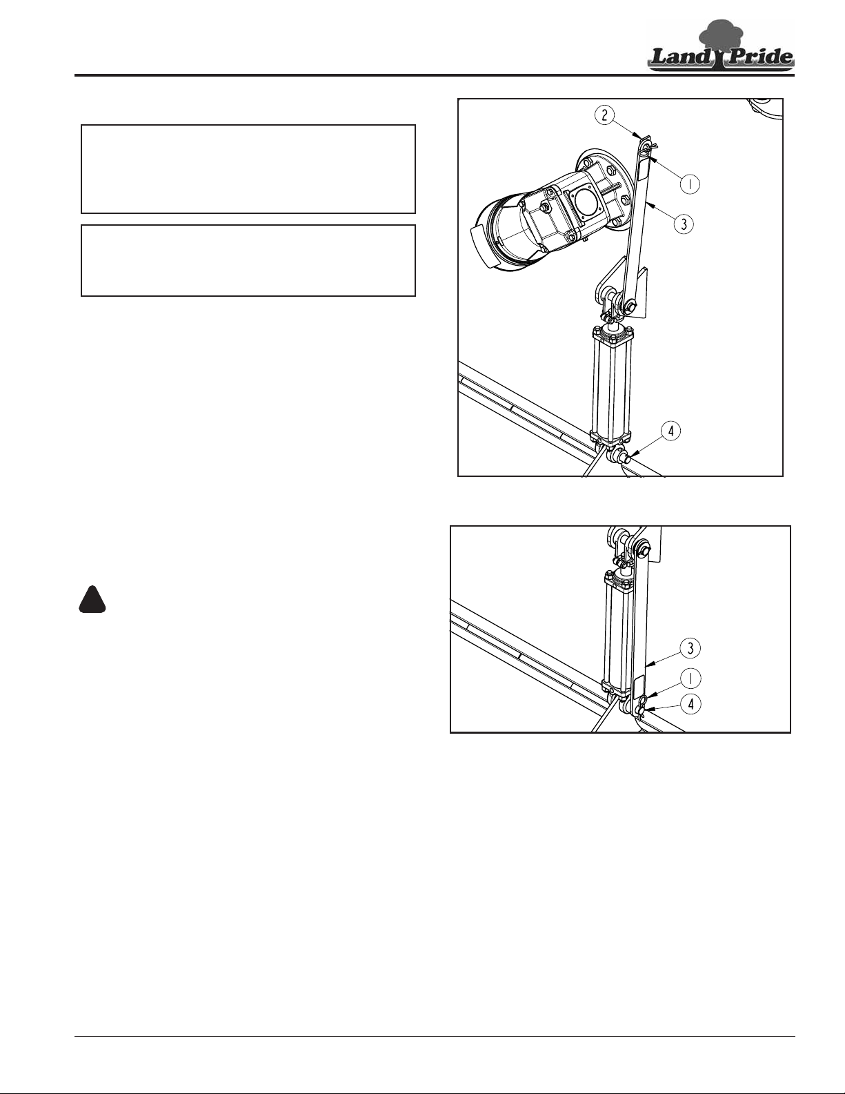
Table of Contents
Section 3: Operating Instructions
Transport Locks
IMPORTANT: Always disengage tractor’s power
take-off & wait for blades to come to a complete stop
before raising cutter wings to transport position.
Wing drivelines, wing gearboxes, and splitter
gearbox can be damaged if driveline is turning.
NOTE: The wings are controlled with hydraulic
folding cylinders. Be certain that the wing hydraulic
hose is properly attached to the tractor and is full of
oil before proceeding.
The cutter wings will need to be raised and locked before
transporting on a roadway, through narrow openings, and
when servicing underside of deck.
1. Disengage tractor power take-off and wait for cutter
blades to come to a complete stop before raising the
wings.
2. Rotate cutter wings fully up with hydraulics.
3. Shut tractor down properly before dismounting. Refer
to “Tractor Shutdown Procedure” on page 17.
4. See Figure 3-3: Remove hairpin cotter (#1) from
storage bracket (#2).
5. See Figure 3-4: Rotate transport lock bar (#3) to
cylinder pin (#4). Secure bar with hairpin cotter (#1).
6. Repeat steps 4 and 5 for the other wing section.
33868
Transport Bar, Storage Position
Figure 3-3
Transporting
!
WARNING
To avoid serious injury or death:
• Always raise wings and set transport locks before
transporting from one work site to another and before
traveling on public roadways. The wings can fall if not
secured with transport locks.
• Select a safe ground speed when transporting. Never travel
at a speed which does not allow adequate control of steering
and stopping, and never exceed 20 mph (32.2 km/h) with
attached equipment. Rough terrain requir es a slower speed.
• When traveling on public roads, use LED lights, slow
moving vehicle sign, clean reflectors, and other adequate
devices to warn operators in other vehicles of your
presence. If implement blocks visibility of slow moving
vehicle sign, relocate sign so it is visible fr om the back at all
times. Always comply with all federal, state, and local laws.
• Watch while making tight turns to ensure that the rear
tractor tires and lower 3-point arms do not make contact
with cutter hitch, driveline or deck. Keep lower 3-point
arms raised at all times when hitched to a pull-type cutter.
1. Select a safe ground speed when transporting from
one area to another. Maximum transport speed for
the Rotary Cutter is 20 mph. DO NOT EXCEED.
2. Be sure to reduce tractor ground speed when turning
and leave enough clearance so the cutter does not
contact obstacles such as buildings, trees or fences.
33867
Transport Bar, Locked Position
Figure 3-4
3. Always raise wings and set transport lock bars before
traveling on public roadways.
4. When traveling on roadways, transport in such a way
that faster moving vehicles may pass you safely. Use
LED flashing lights on the cutter to make yourself
more visible.
5. Shift tractor to a lower gear when traveling over rough
or hilly terrain.
Road Side Cutting
Land Pride recommends the Rotary Cutter be equipped
with chain guards to stop flying objects when cutting road
sides. Refer to “Safety Guards” on page 37.
Use the LED flashing lights on the cutter to make yourself
more visible when cutting road sides.
RC3620 & RCM3620 Rotary Cuters 330-841M9/25/18
33
Page 38
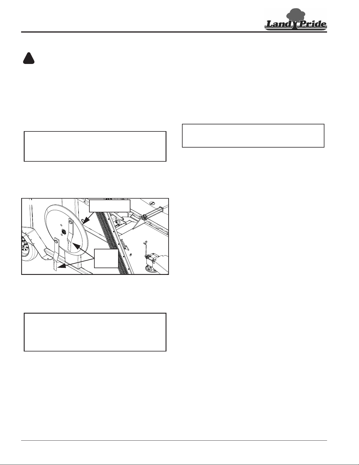
Section 3: Operating Instructions
Table of Contents
Field Set-up
!
WARNING
To avoid serious injury or death:
• The following operational procedur es should be carried out
by the tractor operator. Other persons should not be in the
area. All cutter operations including field set-up should be
stopped when other persons are in the vicinity.
• Clear area to be cut of debris and other unforeseen
removable objects before cutting. Mark non-removable
hazards such as tr ee stumps, post stubs, pr otruding objects,
rocks, drop-offs, holes, etc. with a visible flag.
IMPORTANT: Cutting should not be done in wet
conditions. Wet material will build up on the deck
underside creating need for additional horsepower,
high wear, and poor discharge.
Field Inspection
Thoroughly inspect area to be cut for debris and
unforeseen objects. Remove all potential hazards and
mark any that cannot be removed.
33869
Wing Deck Blade Positioning
Unfold Wings and Set Deck Cutting Height
Refer to Figure 3-5:
IMPORTANT: Cutting blades may become locked
together (overlapped) when the wings are raised for
transport. Operating cutter in this condition will result
in severe deck vibration. Inspect wings for locked
blades prior to power-on operation.
Blade Carrier
Cutting
Blades
Figure 3-5
Refer to Figure 3-4 on page 33:
4. Remove hairpin cotter (#1) and transport lock
bar (#3) from cylinder pin (#4) on both wing sections.
Refer to Figure 3-3 on page 33:
5. Rotate end of transport lock bar (#3) up to storage
lug (#2). Secure with hairpin cotters (#1).
6. Start tractor and lower both wings down.
7. Adjust cutter to field cutting height. See “Adjust Deck
Cutting Height” on page 29.
Set Wing Folding Lever In Float Position
IMPORTANT: The wing folding levers should be in
float position to avoid damage to the wing hydraulic
cylinders and axles while cutting on uneven terrain.
Use the float position of your tractor’s hydraulic system to
provide automatic floating of the wings for varying terrain
conditions. This will ensure that the wing gauge wheels
are in continuous contact with the ground at all times.
Rephasing Lift Cylinders
The rephasing lift cylinders will not function properly if
they are out of phase. This will be noticeable when one
deck is higher or lower than another deck. Retracting one
lift cylinder, more than the other, can cause this situation.
Some tractors with pressure detents will not allow the
hydraulic systems to rephase automatically. To manually
rephase lift cylinders, raise cutter completely up and hold
the tractor hydraulic lever on a few more seconds to give
the cylinders time to rephase. Do this each time you raise
the cutter and when the decks are uneven.
Momentarily reversing the hydraulic lever immediately
after rephasing the lift cylinders allows the cylinders to
retract about 1/2" and will help maintain a level cutter
during transport.
Select Gear Range
Optimum ground speed depends on density of material
being cut, horsepower rating of tractor, and (in some
cases) terrain. Always operate tractor at the cutter’s
full-rated power take-off speed in a gear range that allows
the cutter to make a smooth cut without lugging the
tractor down, usually between 2 to 5 mph. Loss of power
take-off speed will allow the blades to hinge back and
result in ragged, uneven cutting.
1. Inspect blade carriers for locked blades prior to
lowering the wings. Separate locked blades.
2. Start tractor and raise both wings up to release any
tension on the transport lock bars.
3. Without lowering the cutter, shut tractor down before
dismounting. Refer to “Tractor Shutdown
Procedure” on page 17.
34
RC3620 & RCM3620 Rotary Cuters 330-841M 9/25/18
Page 39

Section 3: Operating Instructions
Table of Contents
Engage Blades
IMPORTANT: Cutter blades can lock-up against
each other during start-up and shut-down,
especially if tractor’s power take-off engagement is
“INSTANT ON” and/or “INSTANT OFF”. Follow Blade
Engagement and Blade Disengagement instructions
to help eliminate blade lock up.
1. Select a gear range that will allow the cutter to make a
smooth cut without lugging the tractor down.
See “Select Gear Range” above for detailed
instructions.
2. With wings lowered, increase throttle to a speed just
enough to get the cutter started without stalling tractor
while slowly engaging power take-off. Use tractor’s
power take-off soft start option if available.
3. Visually ensure that all power shafts are rotating and
that the cutter is not vibrating excessively after
ramping up to power take-off speed for at least 3
seconds. If excessive vibration continues after 3
seconds at full power take-off speed, disengage
power take-off immediately, shut down tractor and
remove switch key. Wait for blades to come to a
complete stop before dismounting tractor.
4. Investigate cause if cutter was shut down due to
excessive vibration. See “Blade Operation
Inspection” on page 32 for detailed instructions.
5. If cutter was not shut down, commence forward
cutting operation at full power take-off operating
speed. Make a new gear selection if tractor is lugging
down or if cutter is making a rough cut.
6. Periodically, shut tractor down properly and dismount
to do an inspection. Refer to “Tractor Shutdown
Procedure” on page 17 for proper shut down
procedure.
7. Dismount tractor and check for objects wrapped
around blade spindles. Block deck up before
removing objects.
8. Frequently inspect cutter for loose bolts and nuts.
Tighten all loose hardware as indicated in the
“Torque Values Chart” on page 58.
Disengage Blades
1. Slowly decrease throttle speed until engine idle
speed is reached.
2. Disengage power take-off.
3. Place tractor in park or set park brake, shut tractor
engine off, remove switch key, and wait for blades to
stop before dismounting from tractor.
RC3620 & RCM3620 Rotary Cuters 330-841M9/25/18
35
Page 40

Section 3: Operating Instructions
Table of Contents
General Operating Instructions
Now that you have familiarized yourself with the
Operator’s Manual, completed the Operator’s Checklist,
properly attached your cutter to your tractor, made the
right leveling adjustments, and preset your cutting height,
you’re almost ready to begin using your Land Pride 20'
Smooth Top Rotary Cutter.
It’s now time to do a running operational safety check. If
at any time during this safety check you detect a
malfunction in either the cutter or tractor, shut the tractor
off immediately, remove the key, and make necessary
repairs or adjustments before continuing.
Make sure the tractor’s park brake is engaged, tractor’s
power take-off is disengaged, and the cutter is resting on
the ground with both wings down. Start tractor and back
throttle off until the engine is at a low idle. With tractor’s
rear hydraulic lift control lever, raise the cutter to transport
position making sure that the power take-off shaft is not in
a bind and does not come in contact with the cutter frame.
Lower unit to cutting position and with the tractor still at a
low idle, engage power take-off shaft. If everything is
running smoothly at this point, increase engine rpm until
the tractors engine reaches full power take-off operating
speed which will be either 540 or 1000 rpm. Slowly raise
the cutter to transport height to make sure the driveline
does not bind or chatter. Then return the engine to low
idle, disengage power take-off, and position the
adjustable cylinder stops on the cutter’s hydraulic lift
cylinder so the cutter can be consistently returned to the
same cutting and transport height. Watch while making a
tight turn to ensure that the rear tractor tires do not
contact the deck or hitch. Also, be sure tractor 3-point
arms are raised and will not contact main driveline.
You should now be ready to move to the cutting site.
Never assume an area is clear. Cut only in areas you are
familiar with, have inspected, and know to be free of
debris and unseen objects. Cut extremely tall grass twice
to detect potential hazards. In the event you do strike an
object, stop the tractor and cutter immediately to inspect
cutter and make any necessary repairs before resuming
operation. It pays to inspect a new area and to develop a
plan before you cut.
To produce a clean cut, normal mowing speed will be
between 2-5 mph at full tractor power take-off speed.
Therefore, make a tractor gear and range selection that
will maintain this combination. Generally the quality of cut
will be better at lower ground speeds and cutting denser
ground cover may create the need to slow down. You will
want to avoid very low cutting heights especially on
extremely uneven terrain. Always cut downward on
slopes and avoid crossing the face of steep slopes. Avoid
sharp drops and cross diagonally through dips to prevent
hanging up the tractor and cutter. Slow down in turns and
avoid sharp turns if at all possible. Remember to look
back often.
Now that you’re prepared and well briefed you may begin
cutting. Begin cutting by doing the following:
• Reduce tractor’s engine rpm.
• Make sure cutter wings are on the ground and in
cutting position.
• Engage power take-off, raise engine rpm to the
appropriate power take-off speed, and begin mowing.
Operators of models with a conventional main driveline
must plan ahead and choose a cutting pattern that allows
for wider turns. Try increasing or decreasing ground
speed to determine the effect on quality of cut. With a
little practice you will be pleased with what you and your
Land Pride Smooth Top Cutter can do.
When you are done mowing, need to take a break, or just
need to make a few adjustments to the cutter, remember
to always do the following:
• Reduce tractor’s engine rpm, disengage power take-
off, and stop on level ground.
• Set the park brake, turn off engine, and remove switch
key.
• Stay on the tractor until cutter blades have come to a
complete stop.
36
RC3620 & RCM3620 Rotary Cuters 330-841M 9/25/18
Page 41

Table of Contents
Section 4: Options & Accessories
Section 4: Options & Accessories
Safety Guards
!
DANGER
To avoid serious injury or death:
Rotary Cutters have the ability to discharge objects at high
speeds; therefore, the use of front & rear safety guards is
mandatory with this cutter. Double row chain guards should
be used when cutting along roadways and in areas where
people may be present. Stop blade r otation if bystanders are in
or around the area.
!
WARNING
To avoid serious injury or death:
Keep all safety guards in place. Rotary Cutters have the
ability to discharge objects at high speeds. Use extreme
caution when cutting in areas wher e people may be pr esent. It
is best to operate the cutter when no one is nearby. Stop blade
rotation if someone is in or around the area.
Land Pride offers three types of safety guards to best suit
your application: rubber skirt guards, single row chain
guards, and double row chain guards.
• Rubber skirt guards are designed for light duty
applications.
• Single row chain guards are constructed with a single
row of hanging chain links. They can withstand harsher
applications than rubber skirts.
• Double row chain guards are constructed with two
staggered rows of hanging chain links. The second row
provides an additional barrier for stopping thrown
objects.
Land Pride offers two types of safety guards to best suit
your application: single row chainguards and double row
chainguards.
• Single row chain guards are constructed with a single
row of hanging chain links. They can withstand harsher
applications than rubber skirts.
• Double row chain guards are constructed with two
staggered rows of hanging chain links. The second row
provides an additional barrier for stopping thrown
objects.
Single Row Chain Guards
330-817A Front Single Row Chain guards
330-819A Rear Single Row Chain guards
Tire Options
Land Pride offers three different tires and two axle
arrangements to best suit your application:
• Laminated tires: They are constructed of laminated
layers of solid rubber that will never go flat.
• Used Aircraft tires: They are available in foam filled
and air filled. Both are built tough to withstand the
rugged use a cutter receives and to provide a smoother
ride when transporting from field to field. Foam filled
won’t go flat.
• 6 - Wheel arrangement: Four on transport axle and one
on each wing axle. Available with laminate tires or
aircraft tires.
• 8 - Wheel arrangement: Four on transport axle and two
on each wing axle. Available with laminate tires or
aircraft tires.
Hitch Options
The cutter is factory supplied with the standard clevis
hitch. Other optional hitches are available. See “Hitch
Types” on page 14 for complete description of optional
hitches.
330-225A Standard Clevis Hitch
330-333A Bar-Tite Hitch (Optional)
330-335A Ball Hitch (Optional)
330-334A Pintle Hitch (Optional)
334-045A LP Performance Hitch (Optional)
Double Row Chain Guards
330-818A Front Double Row Chain guards
330-820A Rear Double Row Chain guards
p
RC3620 & RCM3620 Rotary Cuters 330-841M9/25/18
37
Page 42
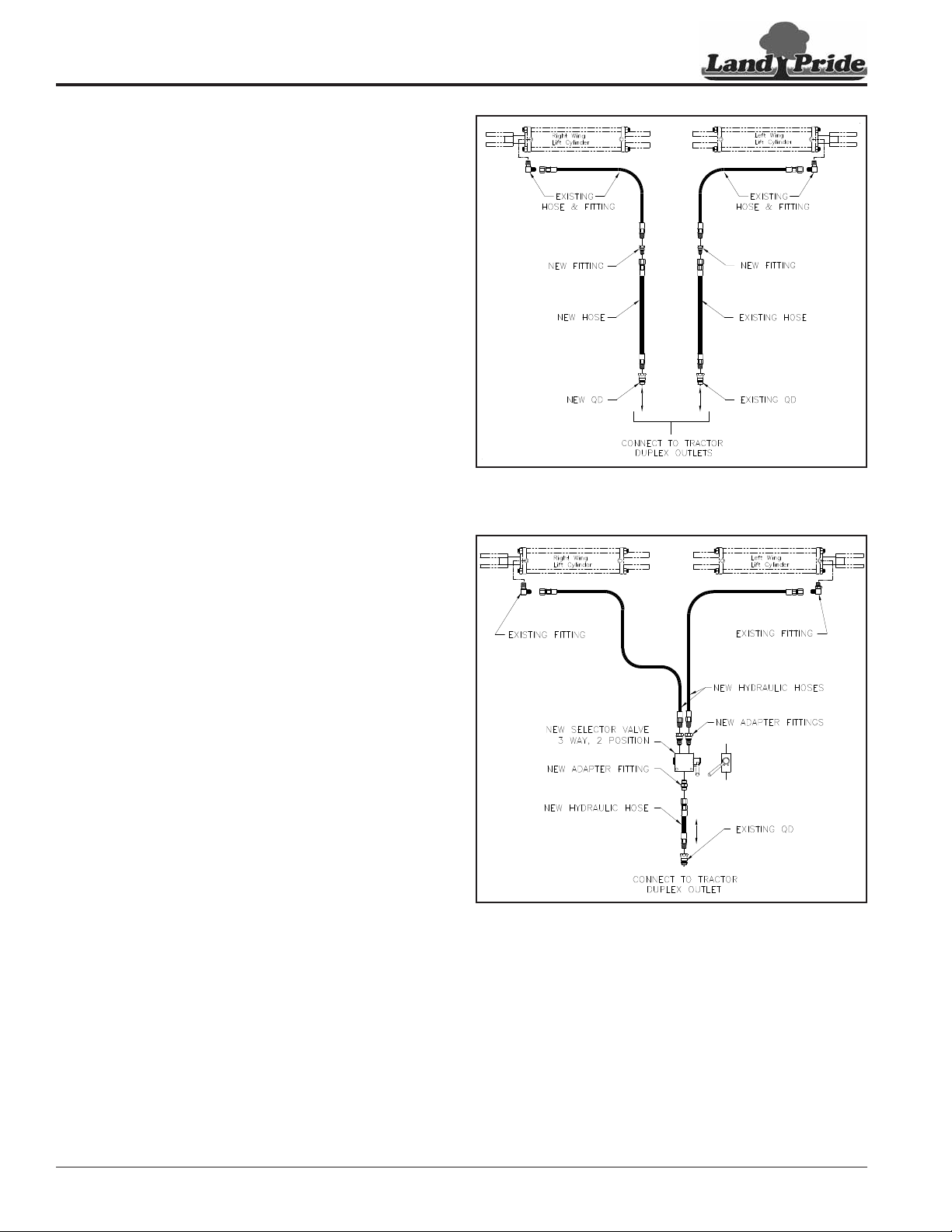
Table of Contents
Section 4: Options & Accessories
Hydraulic Accessories
Land Pride offers two different kits for raising the deck
wings independently to clear small obstacles in the field
without maneuvering around them.
Hydraulic Wing Control Kit
318-316A HYDRAULIC WING CONTROL KIT
Refer to Figure 4-1:
This kit is for tractors with three duplex outlets. It consist
of two adapter fittings, one hose and one quick
disconnect coupling.
39170
Hydraulic Wing Control Kit
Figure 4-1
Selector Control Valve Kit
312-316A SELECTOR CONTROL VALVE KIT
Refer to Figure 4-2:
This kit is for tractors needing only one additional duplex
outlet. It converts one of the tractor’s duplex outlets into
two duplex outlets with a control valve. A selector lever on
the control valve selects which wing cylinder is
operational with the tractor hydraulic control lever. It
attaches to the existing elbow fittings at the wing
cylinders and uses the existing quick disconnect
couplings supplied with the cutter to connect to one of the
tractor’s duplex outlets.
39169
Selector Control Valve Kit
Figure 4-2
38
RC3620 & RCM3620 Rotary Cuters 330-841M 9/25/18
Page 43
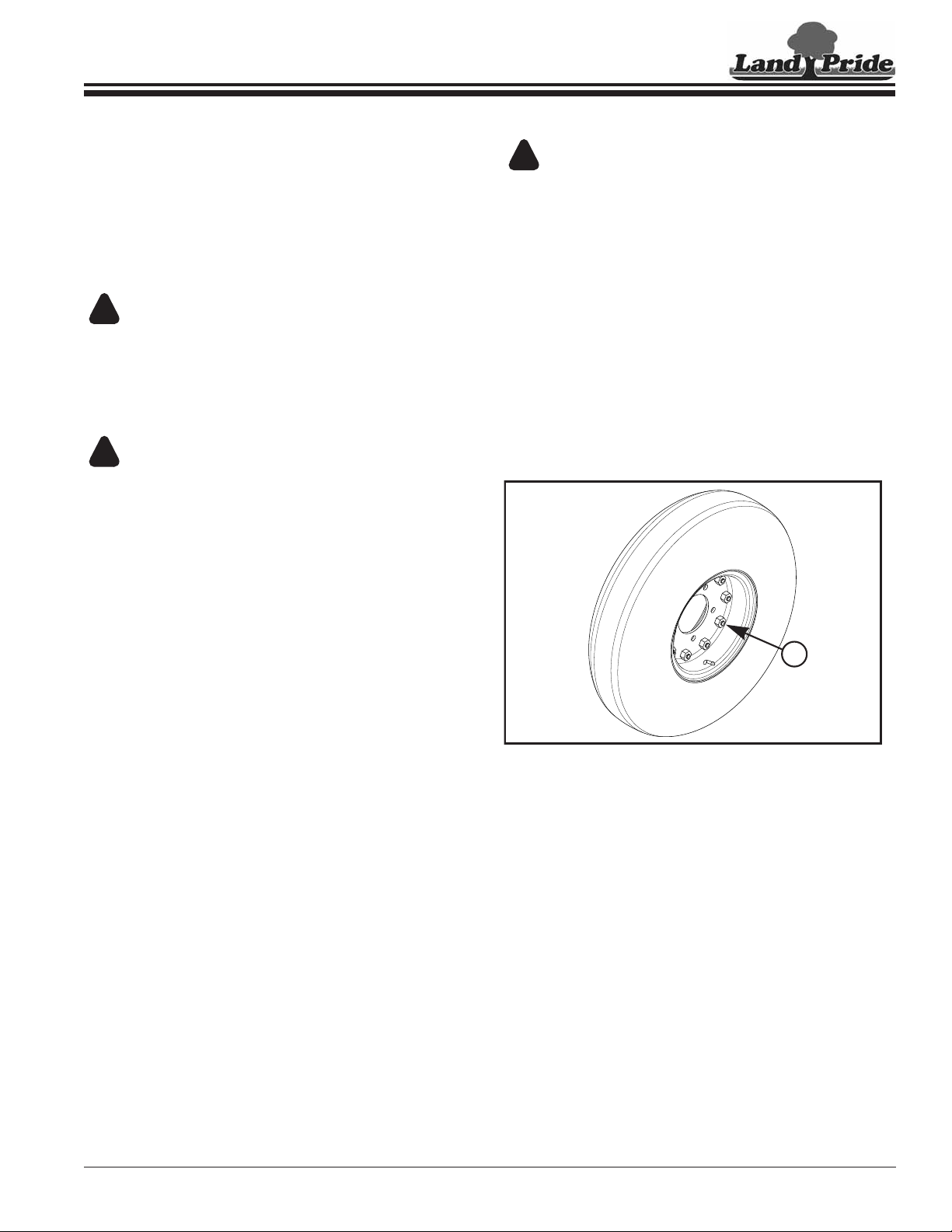
Table of Contents
Section 5: Maintenance & Lubrication
Section 5: Maintenance & Lubrication
General Maintenance Information
Proper servicing and adjustments are key to the long life
of any implement. With careful inspection and routine
maintenance, you can avoid costly downtime and repair.
Check all bolts and pins after using the cutter for several
hours and on a regular basis thereafter to ensure they are
tight and secured. Replace worn, damaged or illegible
safety labels by obtaining new labels from your Land
Pride dealer.
!
DANGER
To avoid serious injury or death: Always secure equipment
with solid, non-concrete supports before working under it.
Never go under equipment supported by concrete blocks or
hydraulics. Concrete can break, hydraulic lines can burst,
and/or hydraulic controls can be actuated even when power to
hydraulics is off.
!
WARNING
To avoid serious injury or death:
• Perform scheduled maintenance. Check for loose
hardware, missing parts, broken parts, structural cracks,
and excessive wear. Make repairs befor e putting implement
back into service. Serious breakdowns can result in injury
or death.
• Always shut tractor down using “Tractor Shutdown
Procedure” provided in this manual before dismounting
tractor.
• Do not alter implement or replace parts on the implement
with other brands. Other brands may not fit properly or
meet OEM (Original Equipment Manufacturer)
specifications. They can weaken the integrity and impair the
safety, function, performance, and life of the implement.
Replace parts only with genuine OEM parts.
• Buildup of debris around moving components and
gearboxes is a fire hazard. Keep rotating parts and
gearboxes free from debris to avoid serious injury and
property damage.
• Improper oil level can cause bearing failure and be a fire
hazard. Maintain proper gearbox oil level to avoid serious
injury and property damage.
Hydraulic System
One of the most important things you can do to prevent
hydraulic system problems is ensure that your tractor's
reservoir remains free of dirt and contamination.
Use a clean cloth to wipe hose ends clean before
attaching them to your tractor. Replace tractor hydraulic
filter element at the prescribed intervals. These simple
maintenances will go a long way to prevent occurrence of
control valve and hydraulic cylinder problems.
Tires
!
WARNING
To avoid serious injury or death:
• Tire changing can be dangerous and should be performed
by trained personnel using correct tools and equipment.
When removing and installing wheels, use wheel handling
equipment adequate for the weight involved.
• Always release all air pressure in air-filled airplane tires
before removing hardware bolting the split rims together.
Not doing so can cause the split rims to blow apart instantly
and could result in serious injury or death.
• When inflating tires, use a clip-on chuck and extension hose
long enough to allow you to stand to one side and NOT in
front of or over the tire assembly. Use a safety cage if
available. Do not over inflate tires.
• Do not weld on or heat a rim. High heat can weaken and/or
warp the rim and damage the tire. Air pressure inside the
tire can increase enough to cause an explosion.
1
33925
Air Filled Airplane Tires with split Rims
Figure 5-1
1. Check tires for low air pressure, missing nuts,
missing lug bolts, wear, separated rubber, and bent,
broken, or cracked wheel rims.
2. Inflate air filled tires to the proper pressure. Refer to
“Tire Inflation Chart” on page 58.
Refer to Figure 5-1:
3. Replace wheel rims and tires as needed with
genuine Land Pride parts. Do not loosen split rim
hardware (#1) until all air pressure in the tire has
been removed.
RC3620 & RCM3620 Rotary Cuters 330-841M9/25/18
39
Page 44
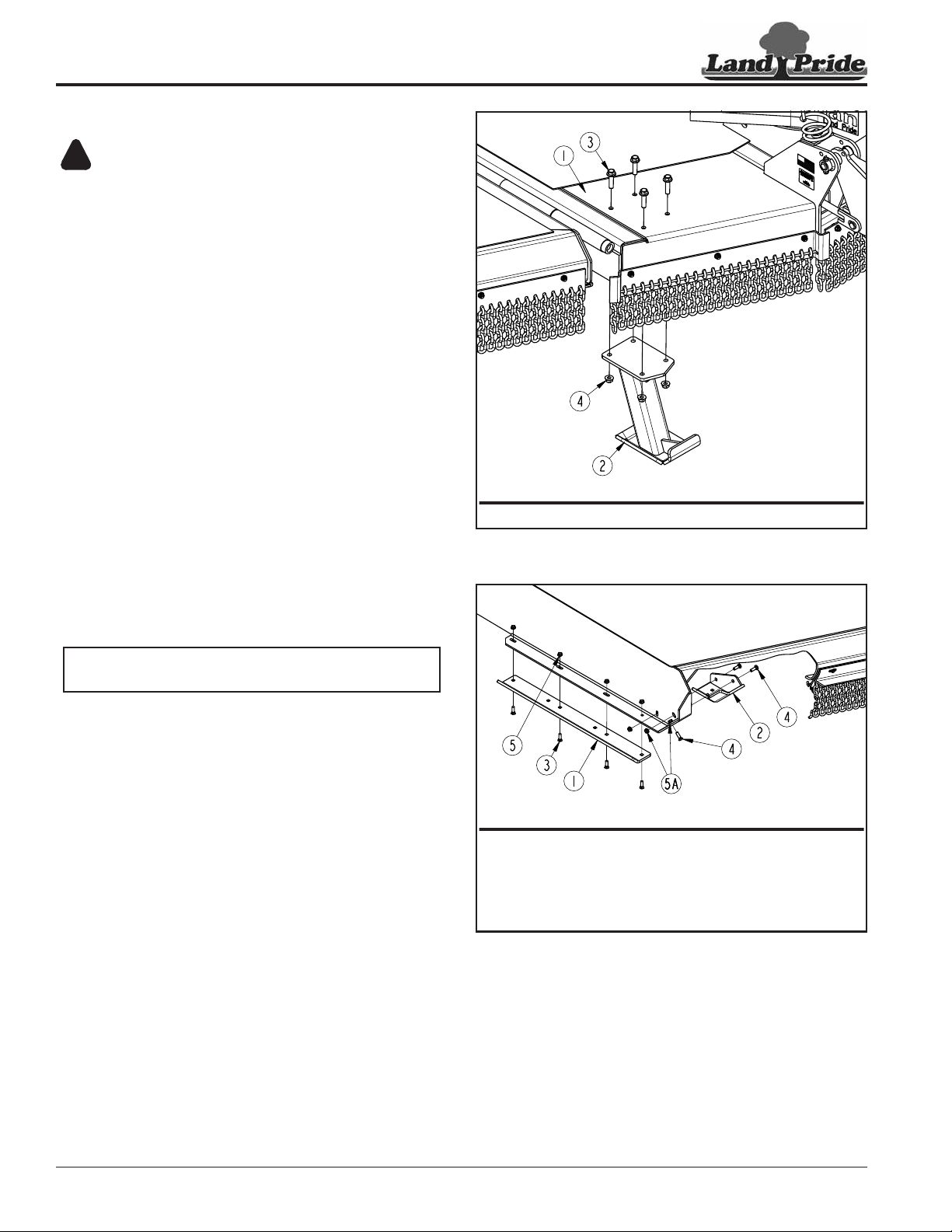
Table of Contents
Section 5: Maintenance & Lubrication
Skid Shoes
!
WARNING
To avoid serious injury or death:
Excessive wear on skid shoes may cause inadequate operation
of cutter and create a safety hazard.
There is one skid shoe mounted on each wing deck and
two skid shoes mounted on the center deck. Check all
skid shoes for wear and replace if necessary. Order only
genuine Land Pride parts from your local Land Pride
dealer.
Center Skid Shoe
Refer to Figure 5-2:
Replace center skid shoes as follows:
1. Remove 1/2" hex whiz nuts (#4), 1/2" hex bolts (#3),
and center skid shoes (#2) from center deck (#1).
2. Attach new skid shoes (#2) to cutter with existing
1/2"-13 x 2" GR5 hex bolts (#3) and secure with 1/2"
hex whiz nuts (#4). Tighten whiz nuts to the correct
torque.
33872
# Part No. Description
2 330-802H CENTER SKID SHOE
Wing Skid Shoe
Refer to Figure 5-3:
NOTE: Wing skid shoes can be reversed and
mounted on the opposite wing to increase their life.
1. Remove 3/8" whiz nuts (#5A), carriage bolts (#4),
and hardened skid shoes (#2) from both wing decks.
2. Remove 3/8" whiz nuts (#5), plow bolts (#3), and
wing skid shoes (#1) from both wing decks.
3. Inspect plow bolts for wear and replaced if needed.
4. Inspect skid shoes (#1) and hardened skid
shoes (#2) for wear. If skid shoes can be reversed
and reused, reattach existing skid shoes to the
opposite wing deck.
5. Attach new/existing hardened skid shoes (#2) to
cutter side panels with removed 3/8"-16 x 1 1/4" GR5
carriage bolts (#4) and whiz nuts (#5A). Do not
torque nuts tight at this time.
6. Attach new/existing skid shoes (#1) to cutter side
panels with new/existing 3/8" -16 x 1 1/4" GR5 plow
bolts (#3) and hex whiz nuts (#5).
7. Tighten whiz nuts (#5 & #5A) to the correct torque.
Center Skid Shoe
Figure 5-2
39151
# Part No. Description
1 330-835D WING SKID SHOE
2 331-120H HARDENED WING SKID SHOE
3 802-466C PLOW 3/8-16X1 1/4 GR5
4 802-155C RHSNB 3/8-16X1 1/4 GR5
5 803-198C NUT HEX WHIZ 3/8-16 PLT
Wing Skid Shoe
Figure 5-3
40
RC3620 & RCM3620 Rotary Cuters 330-841M 9/25/18
Page 45

Table of Contents
Section 5: Maintenance & Lubrication
Cutter Blades
!
DANGER
To avoid serious injury or death:
• Always disconnect driveline from the tractor before
servicing the drivetrain and components powered by the
drivetrain. A person can become entangled in the drivetrain
if the tractor is started and the power take-off is engaged.
• Always secure equipment with solid, non-concr ete supports
before working under it. Never go under equipment
supported by concrete blocks or hydraulics. Concrete can
break, hydraulic lines can burst, and/or hydraulic controls
can be actuated even when power to hydraulics is off.
!
WARNING
To avoid serious injury or death:
• Do not operate cutter with blades that are out-of-balance,
bent, excessively worn, excessively nicked, or with blade
bolts that are excessively worn. Such blades can br eak loose
at high speeds.
• W ait for blades to come to a complete stop befor e accessing
blade bolts through blade bolt access hole.
• W ear eye pr otection and gloves while inspecting, removing,
sharpening, and replacing a blade.
• Do not attempt to straighten a bent blade or weld on a
blade. Do not attempt to modify a blade such as hard
surfacing, heat treating, cold treating, or by any other
method. Always replace blades with new Land Pride blades
to assure safety.
IMPORTANT: Cutting blades must be replaced in
mating pairs. Not replacing both blades will result in
an out-of-balance condition that will contribute to
premature bearing breakdown on the spindle hub
and create structural cracks in the cutter housing.
Always inspect cutting blades before each use. Make
certain they are properly installed and in good working
condition. Replace any blade that is damaged, worn,
bent, or excessively nicked. Never try to straighten a bent
blade! Small nicks can be ground out when sharpening.
Remove cutting blades and sharpen or replace as
follows:
1. Park on a level, solid surface. Place tractor in park or
set park brake. Unfolded wing decks until they are
resting on the ground. Fully extend deck lift cylinders
to lift center and wing decks up.
2. With wings unfolded and deck lift cylinders fully
extended, shut tractor down. Refer to “Tractor
Shutdown Procedure” on page 17.
3. Place solid support blocks under the decks.
4. Start tractor and retract deck lift cylinder until the
center and wing decks are resting securely on the
support blocks.
RC3620 & RCM3620 Rotary Cuters 330-841M9/25/18
41
Page 46
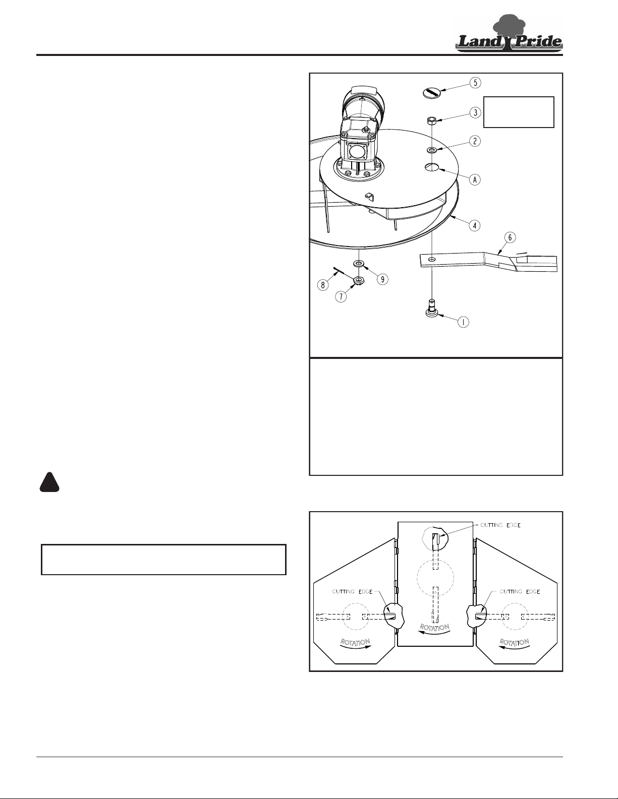
Table of Contents
Section 5: Maintenance & Lubrication
5. Shut tractor down before dismounting. Refer to
“Tractor Shutdown Procedure” on page 17.
6. Disconnect main driveline from the tractor’s power
take-off shaft.
Refer to Figure 5-4:
7. Remove rubber plug (#5). Rotate blade carrier (#4)
until blade bolt (#1) aligns with access hole (A).
8. Unscrew locknut (#3) to remove cutter blade (#6).
Blade bolt (#1) is keyed and will not turn freely.
9. Both blades should be sharpened at the same angle
as the original cutting edge and must be replaced or
re-ground at the same time to maintain proper
balance in the cutting unit. The following precautions
should be taken when sharpening blades:
a. Do not remove more material than necessary.
b. Do not heat and pound out a cutting edge.
c. Do not grind blades to a razor edge. Leave a blunt
cutting edge approximately 1/16" thick.
d. Always grind cutting edge so end of blade remains
square to cutting edge and not rounded.
e. Do not sharpen back side of blade.
f. Both blades should weigh the same with not more
than 1 1/2 oz. difference. Unbalanced blades will
cause excessive vibration which can damage
gearbox bearings and create structural cracks.
Refer to Figure 5-5:
10. Carefully check cutting edges of blades in relation to
blade carrier rotation to ensure correct blade
placement. Cutter blades must be installed with
cutting edge leading in rotation.
Refer to Figure 5-4:
Use 1-11/16"
Socket Wrench
On Blade Nut #3
33871
Land Pride Cutter Blade Parts
# Part No. Part Description
318-586A BLADE BOLT KIT (Item No’s 1, 2, & 3)
1 802-277C BLADE BOLT 1 1/8-12 x 3 7/16 WITH KEY
2 804-147C WASHER FLAT 1 HARD ASTMF436
3 803-170C NUT HEX TOP LOCK 1 1/8-12 PLATE
4 330-796H BLADE CARRIER
5 840-273C PLUG LP 3" ID RUBBER
6 820-249C CUTTER BLADE, CW (Center Deck)
6 820-249C CUTTER BLADE, CW (Right Wing)
6 820-168C CUTTER BLADE, CCW (Left Wing)
!
WARNING
To avoid serious injury or death: A locknut that has been
Cutter Blade Assembly
Figure 5-4
removed can lose its thr ead locking properties. Reusing a used
locknut can result in a thr own blade. Always use a new locknut
when installing blades.
IMPORTANT: Examine blade bolts and their flat
washers for excessive wear and replace if worn.
11. Insert blade bolt (#1) through blade (#6),
dishpan (#4), and flat washer (#2). Secure blade with
a new locknut (#3) and torque to 450 ft-lbs.
12. If replacing dishpan (#4), nut (#7) on gearbox output
shaft should be torqued to 550 ft-lbs. minimum and
secured with cotter pin (#8) with both legs bent
opposite directions around the nut.
CCW
CW
13. Replace rubber plug (#5).
14. Reconnect main driveline to tractor power take-off
shaft.
42
RC3620 & RCM3620 Rotary Cuters 330-841M 9/25/18
Direction of Blade Rotation
Figure 5-5
CW
Page 47
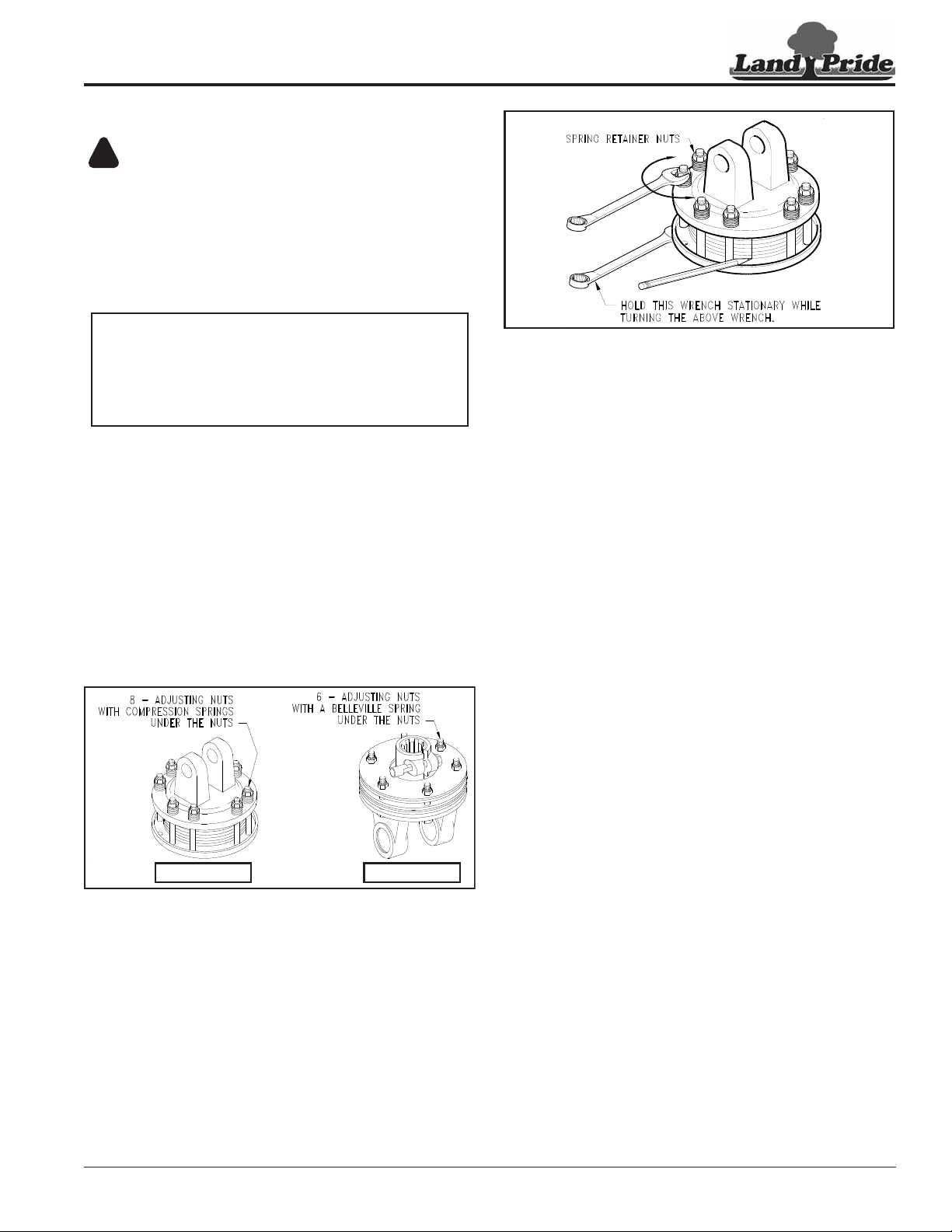
Table of Contents
Section 5: Maintenance & Lubrication
Drivelines With Slip Clutches
!
WARNING
To avoid serious injury or death:
• Always shut tractor down using “Tractor Shutdown
Procedure” provided in this manual before dismounting
tractor.
• A slip clutch that has been in use or has slipped for as little
as only two or three seconds during run-in may be too hot
to touch. Allow a hot clutch to cool before working on it.
IMPORTANT: Prior to initial operation and after 10
days of inactivity, slip friction disks to remove
oxidation and moisture. Moisture allows disks to slip
easily. Oxidation can prevent disk from slipping
causing driveline damage. This damage is NOT
covered under the warranty.
Cutter drive components are protected from shock loads
by a friction slip clutch. The clutch must be capable of
slippage during operation to protect the gearbox,
driveline, and other drive train parts.
Friction clutches should be “run-in” prior to initial
operation and after long periods of inactivity to remove
any oxidation that may have accumulated on the friction
surfaces. Repeat “run-in” instructions at the beginning of
each season and when moisture and/or condensation
seizes the inner friction plates.
Refer to Figure 5-6 to determine which friction clutch your
cutter has. Follow “run-In” instructions on the following
pages for your specific clutch type.
26619
Type A Clutch Type B Clutch
Clutch Types
Figure 5-6
13693
Type A Clutch Run-In
Figure 5-7
Type A Clutches
Clutch Run-In
Refer to Figure 5-7:
1. Using a pencil or other marker, scribe a line across the
exposed edges of the clutch plates and friction disks.
2. Carefully loosen each of the 8 spring retainer nuts by
exactly 2 revolutions. It will be necessary to hold hex
end of retainer bolt in order to count the exact
number of revolutions.
3. Make sure the area is clear of all bystanders and
machine is safe to operate.
4. Start tractor and engage power take-off drive for 2-3
seconds to permit slippage of the clutch surfaces.
Disengage power take-off, then re-engage a second
time for 2-3 seconds. Disengage power take-off, shut
off tractor, and remove key. Wait for all components to
stop before dismounting from tractor.
5. Inspect clutch and ensure that the scribed markings
made on the clutch plates have changed position.
Slippage has not occurred if any two marks on the
friction disk and plate are still aligned. A clutch that
has not slipped must be disassembled to separate
the friction disk plates. See “Clutch Disassembly,
Inspection & Assembly” below.
6. Tighten each of the 8 spring retainer nuts on the
clutch housing exactly 2 revolutions to restore clutch
to original setting pressure.
7. Allow clutch to cool to ambient temperature before
operating again. Clutch is now ready for use.
8. The clutch should be checked during the first hour of
cutting and periodically each week. An additional set
of scribe marks can be added to check for slippage.
See Figure 5-9 to adjust spring length.
RC3620 & RCM3620 Rotary Cuters 330-841M9/25/18
43
Page 48
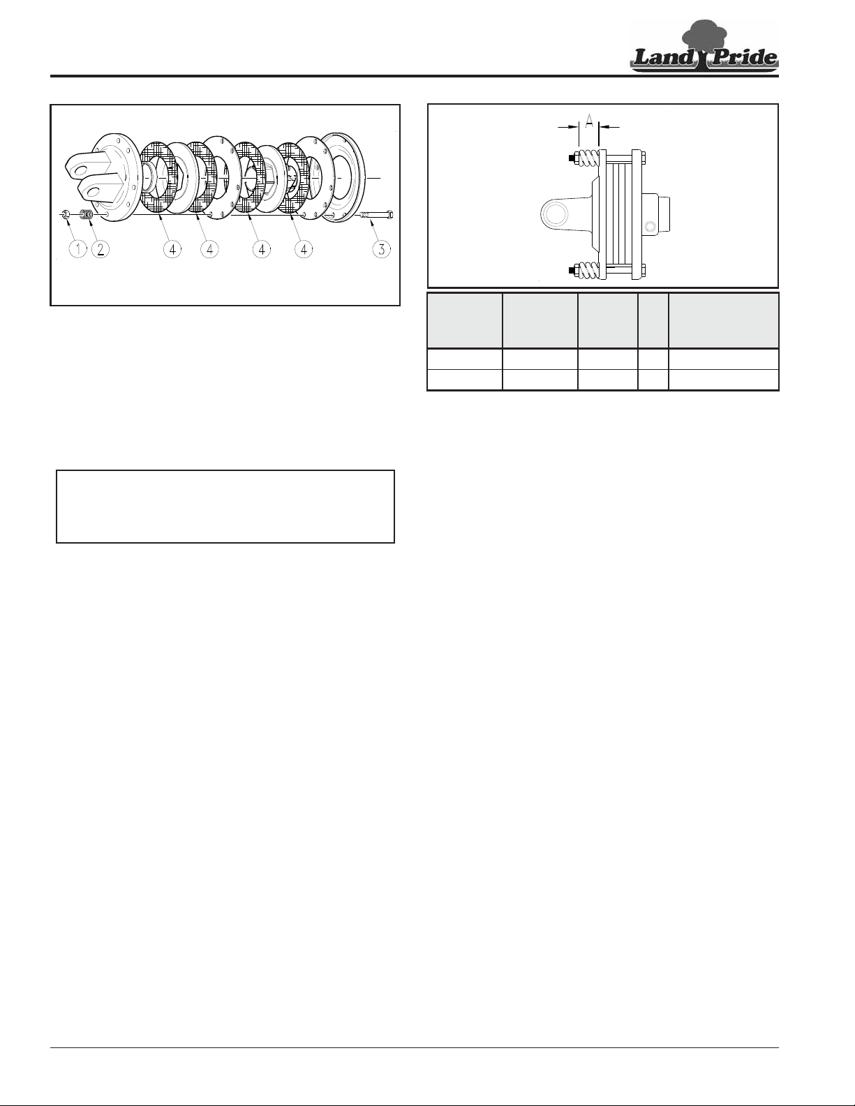
Table of Contents
Section 5: Maintenance & Lubrication
14714
IMPORTANT: Keep track of order and orientation of
your clutch components during disassembly
Type A Clutch Assembly
Figure 5-8
Clutch Disassembly, Inspection & Assembly
Refer to Figure 5-8:
If clutch run-in procedure above indicated that one or more
friction disks did not slip, then the clutch must be
disassembled to separate the friction disks.
Disassembly
IMPORTANT: Not all clutches are assembled the
same with the same number of components. Be
sure to keep track of order and orientation of your
clutch components during disassembly.
1. Removing spring retainer nuts (#1), springs (#2), and
bolts (#3).
2. Separate disk (#4) from metal surfaces adjacent to
them.
Inspection
Inspect all parts for excessive wear and condition. Clean
all parts that do not require replacement.The original
friction disk thickness is 1/8" (3.2mm) and should be
replaced if thickness falls below 3/64" (1.1mm). If
clutches have been slipped to the point of “smoking”, the
friction disks may be damaged and should be replaced.
Heat build-up may also affect the yoke joints.
Driveline
No.
826-494C Wings 540/1000 5 1.32"
826-495C Center 540/1000 5 1.32"
Driveline
Location
Type A Clutch Adjustment
power
take-off
Speed
Figure 5-9
Cat
No.
Spring Height
A (inches)
24600
Assembly
1. Reassemble each friction disk (#4) next to the metal
plate it was separated from.
2. Install bolts (#3) through end plates and intermediate
plates as shown.
3. Place springs (#2) over the bolts and secure with
nuts (#1).
Refer to Figure 5-9:
4. Progressively tighten each spring retainer bolt until
correct spring height “A” is reached.
44
RC3620 & RCM3620 Rotary Cuters 330-841M 9/25/18
Page 49
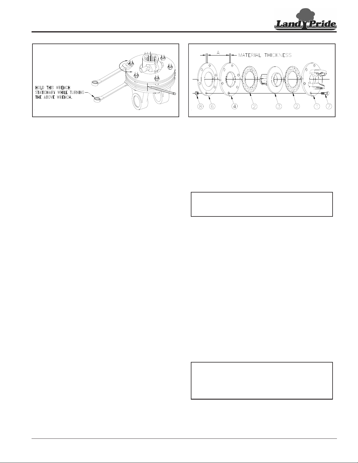
Table of Contents
Section 5: Maintenance & Lubrication
26618
Type B Clutch Run-In
Figure 5-10
Type B Clutches
Clutch Run-In
Refer to Figure 5-10:
1. Using a pencil or other marker, scribe a line across the
exposed edges of the clutch plates and friction disks.
2. Carefully loosen each of the 6 nuts by exactly 1
revolution. It will be necessary to hold hex end of
retainer bolt in order to count exact number of
revolutions.
3. Make sure the area is clear of all bystanders and
machine is safe to operate.
4. Start tractor and engage power take-off drive at idle
for 2-3 seconds to permit slippage of friction plates.
Disengage power take-off, shut off tractor and
remove key. Wait for all components to come to a
complete stop before dismounting from tractor.
5. Inspect clutch to ensure that the scribed markings
made on the clutch plates and friction disc have
changed positions. If any two marks are still aligned,
then the clutch did not slip as it should. Skip to
step 8 if all clutch plates slipped.
6. If the friction clutch did not slip, loosen the nuts one
more revolution. Make sure the nuts have full thread
engagement on the bolt and then repeat steps 4 - 5.
7. A clutch that does not slip must be disassembled to
separate the friction disk plates. See “Clutch
Disassembly, Inspection & Assembly” below.
8. Tighten each of the nuts on the clutch back to their
original location to restore clutch pressure.
9. Allow clutch to cool to ambient temperature before
operating again. Clutch is now ready for use.
10. The clutch should be checked during the first hour of
cutting and periodically each week. An additional set
of scribe marks can be added to check for slippage.
26637
Type B Clutch (2-Plate Assembly)
Used With Drivelines 826-715 & 826-716C
Figure 5-11
Clutch Disassembly, Inspection & Assembly
Refer to Figure 5-11:
The clutch must be disassembled into its separate friction
disks if clutch run-in procedure indicated that one or more
friction disks did not slip. See disassembly instructions.
Disassembly
IMPORTANT: Do not remove nuts (#8) from
bolts (#7) until after Belleville spring (#6) is relaxed
and not pressing against any of the six nuts (#8).
1. Unscrew nuts (#8) equal amounts until all belleville
spring tension is removed. Do not remove nuts until
tension against all nuts has been removed.
2. Remove nuts (#8) and bolts (#7).
3. Separate all friction disks (#2) from plates (#4 & #5),
hub (#3) and yoke flange (#1).
Inspection
Inspect all parts for excessive wear and condition. Clean
all parts that do not require replacement.The original
friction disk thickness is 1/8" (3.2mm) and should be
replaced if thickness falls below 3/64" (1.1mm). If
clutches have been slipped to the point of “smoking”, the
friction disks may be damaged and should be replaced.
Heat build-up may also affect the yoke joints.
Assembly
1. Reassemble each friction disk (#2) next to the metal
plate it was separated from.
2. Install bolts (#7) through end plates and intermediate
plates as shown and secure with nuts (#8).
IMPORTANT: Measurement “A” is an approximate
gap. Variations in spring force and friction materials
may cause some differences in torque values.
Tightening nuts (#8) 1/6 of a turn will compress
belleville spring (#6) 0.25 mm (.010”).
3. Tighten belleville spring (#6) until spring is tight
against drive plate (#4) & then back nuts (#8) up
2 2/3 revolutions, “A” should = 4.0 mm (0.157”).
RC3620 & RCM3620 Rotary Cuters 330-841M9/25/18
45
Page 50

Table of Contents
Section 5: Maintenance & Lubrication
Long-Term Storage
Clean, inspect, service, and make necessary repairs to
the cutter when storing it for long periods and when
storing it at the end of a working season. This will help
ensure the cutter is ready for field use the next time you
hook-up to it.
!
DANGER
To avoid serious injury or death:
• Always disconnect driveline from the tractor before
servicing the drivetrain and components powered by the
drivetrain. A person can become entangled in the drivetrain
if the tractor is started and the power take-off is engaged.
• Always secure equipment with solid, non-concr ete supports
before working under it. Never go under equipment
supported by concrete blocks or hydraulics. Concrete can
break, hydraulic lines can burst, and/or hydraulic controls
can be actuated even when power to hydraulics is off.
1. Clean off any dirt and grease that may have
accumulated on the cutter and moving parts. Scrape
off compacted dirt from the bottom of deck and then
wash surface thoroughly with a garden hose. A
coating of oil may also be applied to the lower deck
area to minimize oxidation.
2. Check blades and blade bolts for wear and replace if
necessary. See “Cutter Blades” on page 41.
3. Inspect for loose, damaged, or worn parts and adjust
or replace as needed.
4. Repaint parts where paint is worn or scratched to
prevent rust. Ask your Land Pride dealer for aerosol
touch-up paint. Paint is also available in touch-up
bottles with brush, quarts, and gallon sizes by adding
TU, QT, or GL to the end of the aerosol part number.
Ordering Replacement Parts
Land Pride offers equipment in factory standard Beige
with black highlights. This implement may also be
purchased in Orange, Green, or Red.
When ordering an optional color, the suffix number
corresponding to the color must be added at the end of
the part number. Parts ordered without the suffix number
will be supplied in factory standard colors.
81 . . . . . . . Green
82 . . . . . . . Orange
For example, if you are ordering a replacement part with
part number 555-555C and the existing part is orange,
then add the suffix 82 to the end of the number to make
the part number read 555-555C82.
83 . . . . . . . Red
85 . . . . . . . Black
Land Pride Aerosol Touch-up Paint
Part No. Part Description
821-011C PAINT LP BEIGE SPRAY CAN
821-054C PAINT MEDIUM RED SPRAY CAN
821-058C PAINT GREEN SPRAY CAN
821-066C PAINT ORANGE SPRAY CAN
821-070C PAINT GP GLOSS BLACK SPRAY CAN
5. Replace all damaged or missing guarding and
decals.
6. Lubricate as noted in “Lubrication Points” starting
on page 47.
7. Store cutter on a level surface in a clean, dry place.
Inside storage will reduce maintenance and make for
a longer cutter life.
8. Follow all unhooking instructions on page 26 when
disconnecting tractor from cutter.
46
RC3620 & RCM3620 Rotary Cuters 330-841M 9/25/18
Page 51
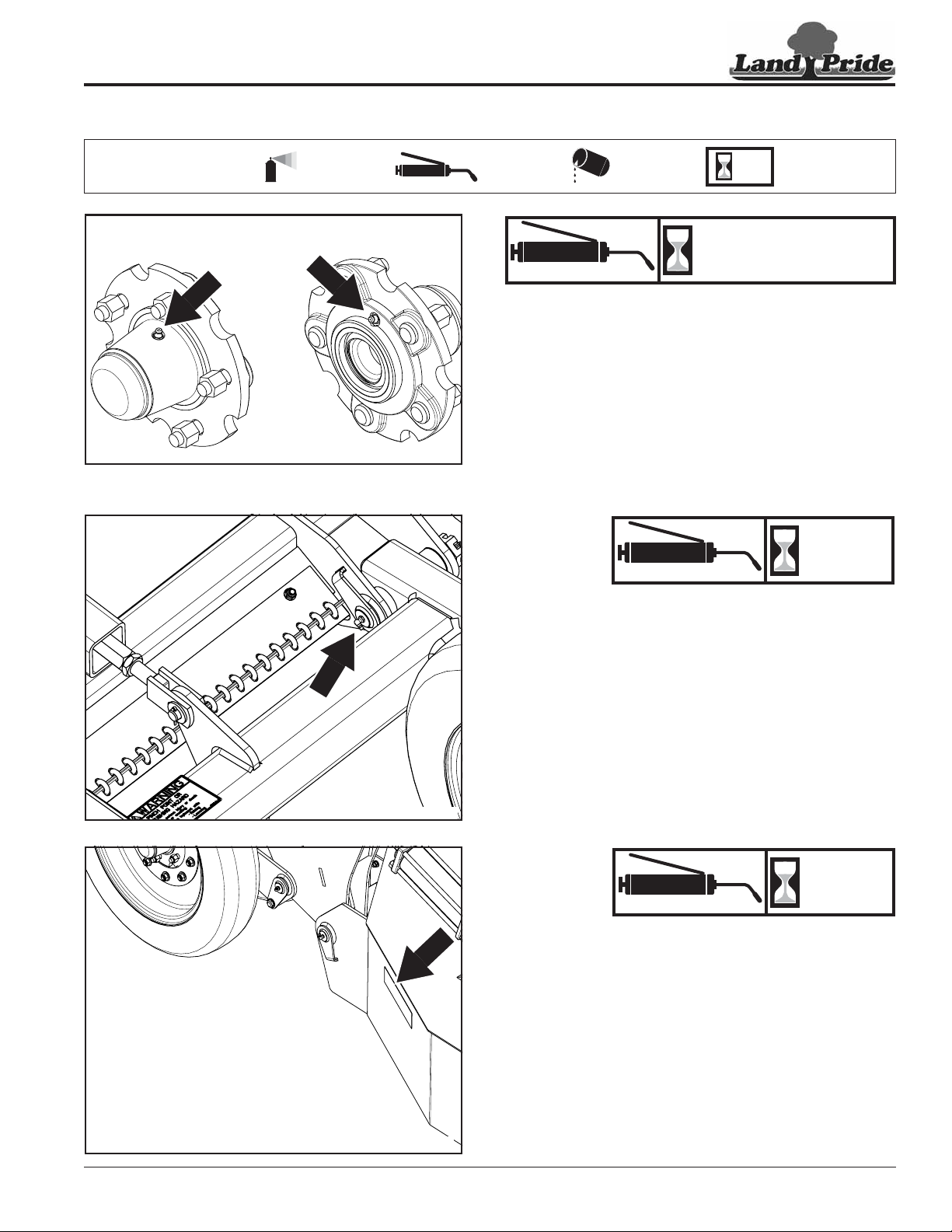
Section 5: Maintenance & Lubrication
Lubrication Points
Table of Contents
Lubrication
Legend
Multi-purpose
spray lube
30184
Multi-purpose
grease lube
Multi-purpose
oil lube
50
Hrs
50
Hours
Axle Hub Bearing
Type of Lubrication: Multi-Purpose Grease
Grease wheel bearings every 50 hours.
1 - zerk per wheel (zerk can be on either side)
Quantity = 2 pumps
Repack wheel bearings annually
Intervals in hours at which
lubrication is required
Repack
Annually
50
Hours
33874
Center Axle Pivots
2 - zerks (left and right side of center axle)
Type of Lubrication: Multi-Purpose Grease
Quantity = As required
50
Hours
Wing Axle Pivots
2 - zerks (1 per wing axle arm pivot)
Type of Lubrication: Multi-Purpose Grease
Quantity = As required
33875
RC3620 & RCM3620 Rotary Cuters 330-841M9/25/18
47
Page 52
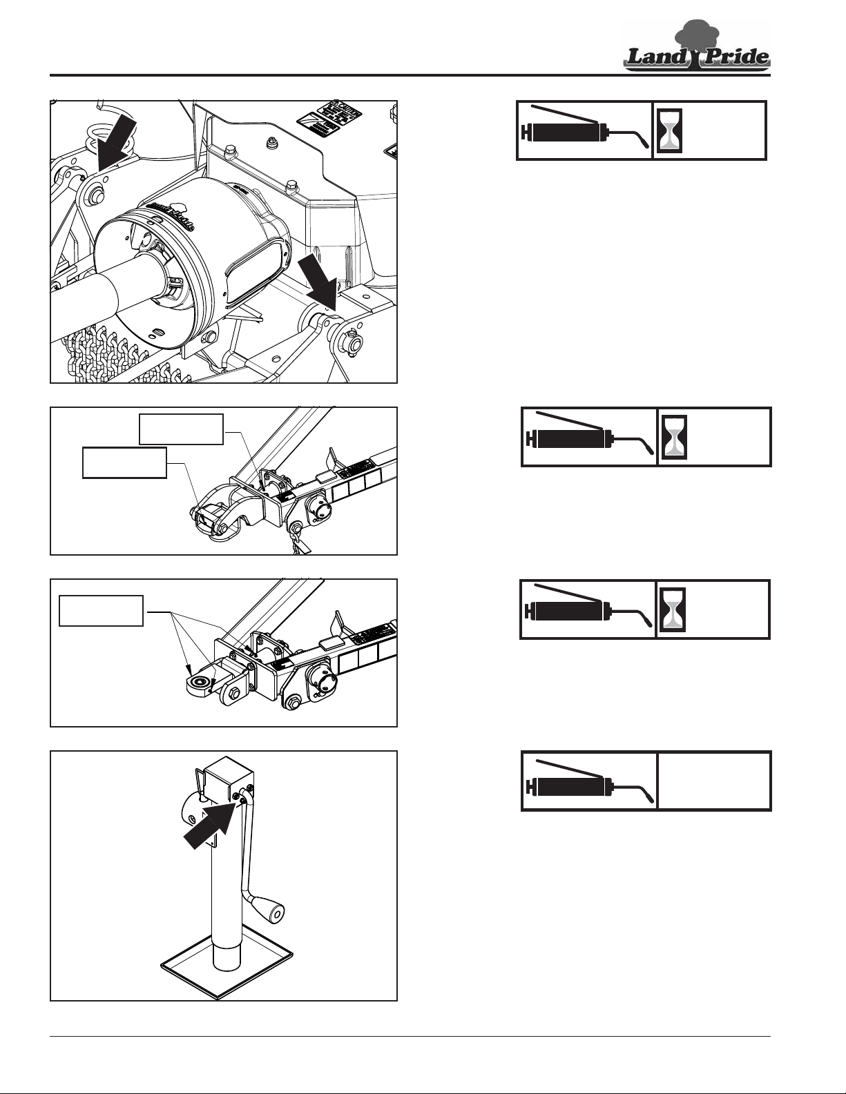
Table of Contents
Section 5: Maintenance & Lubrication
50
Hours
Hitch Frame
2 - zerks
Type of Lubrication: Multi-Purpose Grease
Quantity = As required
33876
Grease Zerk
Location
Grease Zerk
Locations
Grease Zerk
Location
37581
26599
37725
50
Hours
LP Performance Hitch (Optional)
2 - zerks
Type of Lubrication: Multi-purpose Grease
Quantity = As required
50
Hours
Bar-Tite Hitch (Optional)
3 - zerks
Type of Lubrication: Multi-purpose Grease
Quantity = As required
As
Needed
Park Jack
1 - zerk
Type of Lubrication: Multi-purpose Grease
Quantity = As required
Frequency = As needed and when unhooking for
longterm storage.
48
RC3620 & RCM3620 Rotary Cuters 330-841M 9/25/18
Page 53
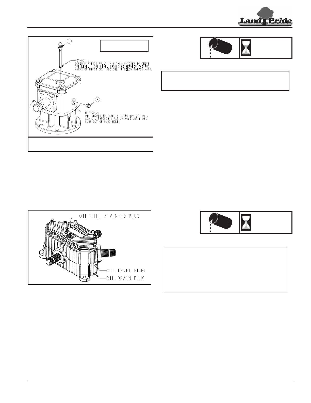
Table of Contents
Section 5: Maintenance & Lubrication
Do Not Overfill
NOTE: Use a suction or siphon pump to drain
gearbox of oil when there is not an oil drain plug.
33877
8
Hours
Gearbox
IMPORTANT: Do not overfill gearbox with oil. Oil will
expand when hot. Make sure implement is level and oil
is cool before checking oil level.
Method 1: With a wrench, unscrew top vented dipstick (#1).
Wipe oil from dipstick and screw dipstick in without
tightening. Unscrew dipstick and check oil on dipstick. If
below bottom level mark, add recommended gear lube
through dipstick hole until oil reaches top mark on dipstick.
Reinstall vented dipstick and tighten.
Method 2: Remove side oil plug (#2). If oil is below bottom
of plug hole, add recommended gear lube through top
dipstick hole until oil flows out of side plug hole. Reinstall
and tighten side oil plug (#2) and vented dipstick (#1).
Type of Lubrication: 80-90W EP Gear Lube
Quantity = Fill until oil reaches top mark on dipstick or
begins to flow out side plug hole in gearbox.
39463
8
Hours
Divider Box
IMPORTANT: Do not overfill gearbox with oil. Oil will
expand when hot. Make sure implement is level and
oil is cool before checking oil level.
If oil has been removed from the gearbox, refill
gearbox to plug level or full mark on the dipstick.
Allow time for air to bleed up from the lower cavity,
and then recheck.
Instructions: Remove oil level plug. If oil is below bottom of
plug hole, add recommended gear lube through oil
fill/vent plug hole until oil flows out of oil level plug hole.
Reinstall and tighten oil level plug and oil fill/vent plug.
Type of Lubrication: 80-90W EP
Quantity = Fill until oil begins to flow out oil level plug hole in
gearbox.
RC3620 & RCM3620 Rotary Cuters 330-841M9/25/18
49
Page 54
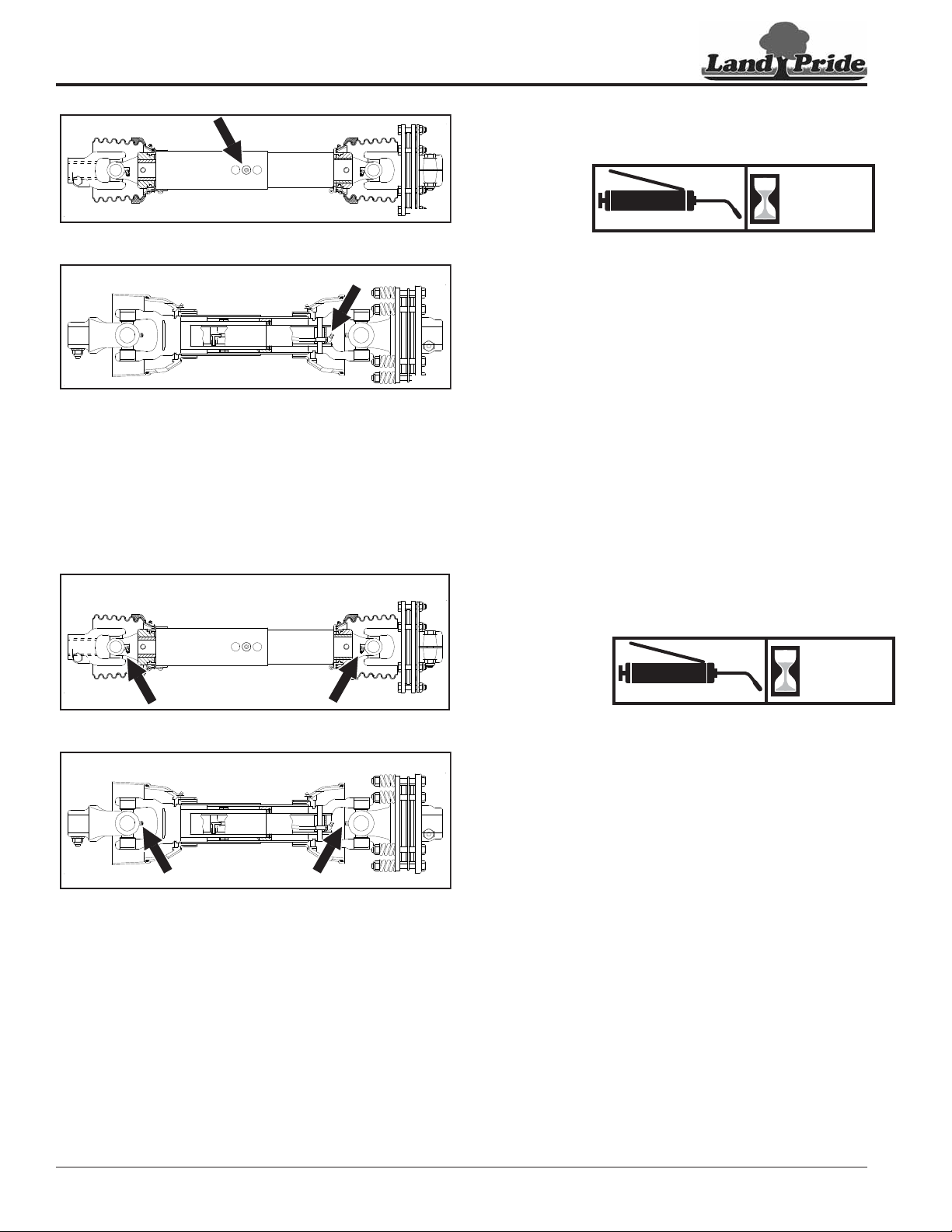
Table of Contents
Section 5: Maintenance & Lubrication
Drivelines with external profile grease point
33911
8
Hours
Zerk Located on end of plastic outer tube
Drivelines with internal profile tube grease point
Drivelines with external profile grease point
Wing Driveline Profile Tubes
Type of Lubrication: Multi-purpose Grease
Quantity = Coat Generously
23564
8
Hours
33911
Wing Driveline Joints
Type of Lubrication: Multi-purpose Grease
23563
Drivelines with internal profile grease point
50
RC3620 & RCM3620 Rotary Cuters 330-841M 9/25/18
Page 55
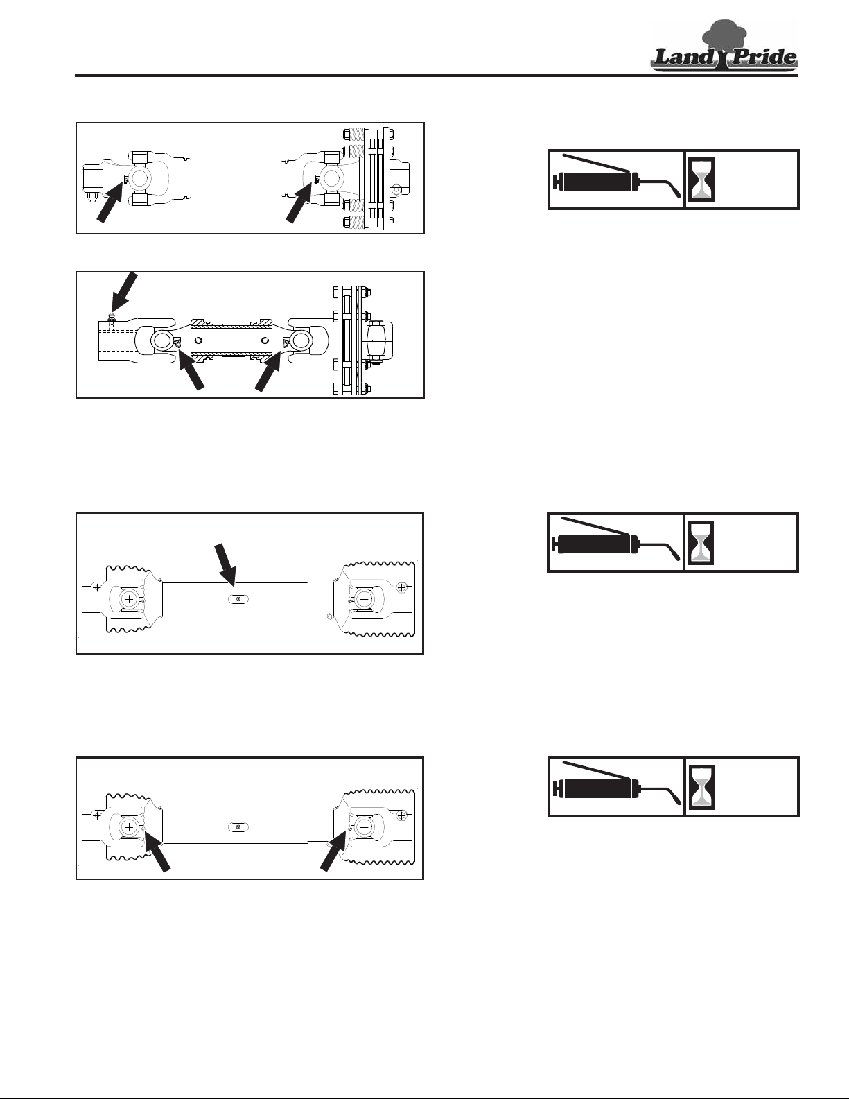
Table of Contents
Section 5: Maintenance & Lubrication
8
Hours
23563
Driveline with clamp type u-joint on both ends
33910
Driveline with clamp type u-joint on slip clutch end only
Zerk located through slot in plastic outer tubes
23567
Intermediate Driveline Joints
Type of Lubrication: Multi-purpose Grease
8
Hours
Conventional Main Driveline Profile Tubes
Type of Lubrication: Multi-purpose Grease
Quantity = Coat Generously
23567
Conventional Main Driveline Joints
Type of Lubrication: Multi-purpose Grease
RC3620 & RCM3620 Rotary Cuters 330-841M9/25/18
8
Hours
51
Page 56
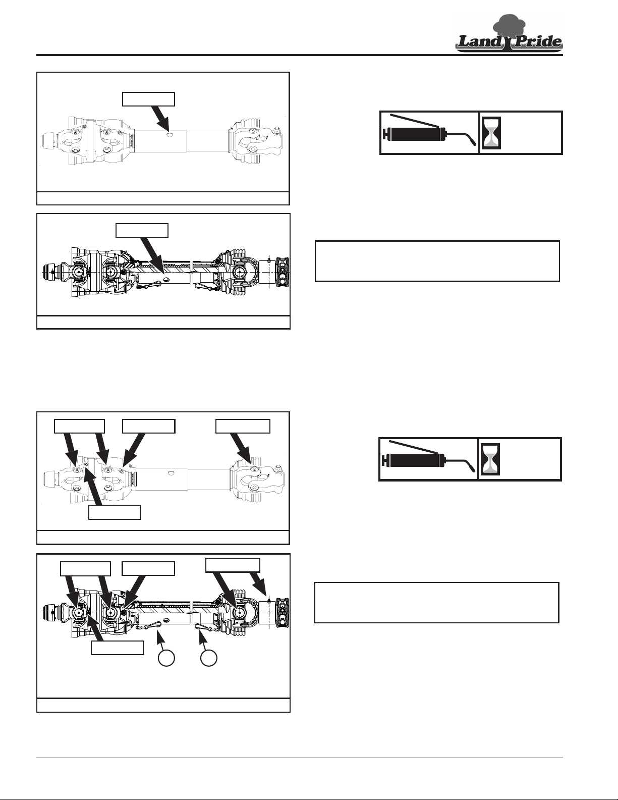
Table of Contents
Section 5: Maintenance & Lubrication
Zerk Located through slot in tube
8-10 pumps
CV Driveline without overrunning clutch
8-10 pumps
CV Driveline with overrunning clutch
23556
39280
8
Hours
CV Main Driveline Profile Tubes
With External Grease Point
CV = Constant Velocity
Type of Lubrication: Multi-purpose Grease
Quantity = 8-10 pumps
IMPORTANT: To extend the life of the constant
velocity joint, extensive lubrication must be
performed every 8 hours of operation.
2-3 pumps 2-3 pumps
4-5 pumps
CV Driveline without overrunning clutch
2-3 pumps
4-5 pumps
IMPORTANT: Attach safety chain (#1) to tractor frame.
Attach safety chain (#2) to cutter frame.
CV Driveline with overrunning clutch
4-6 pumps
4-6 pumps
23556
2-3 pumps
21
39280
8
Hours
CV Main Driveline Joints
CV = Constant Velocity
Type of Lubrication: Multi-purpose Grease
For instructions on how to access grease zerks shown in
Figure 5-12, see “Accessing CV Driveline Joints” on
page 53.
IMPORTANT: To extend the life of the constant
velocity joint, extensive lubrication must be
performed every 8 hours of operation.
• The constant velocity joint should be greased in a
straight position forcing grease through the passages
and into the cavity. After lubrication, grease should be
visible around the ball joints.
• Grease fittings located on the u-joints should be
lubricated every 8 hours of operation.
Figure 5-12
52
RC3620 & RCM3620 Rotary Cuters 330-841M 9/25/18
Page 57
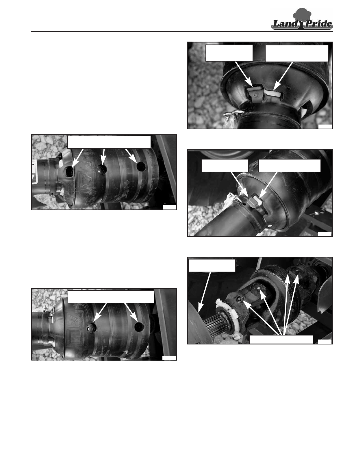
Table of Contents
Section 5: Maintenance & Lubrication
Accessing CV Driveline Joints
Refer to Figure 5-12 on page 52:
There are two ways the constant velocity driveline joints
shown in Figure 5-12 can be accessed for lubrication.
One is through holes in the driveline shield and the other
is to slide the shields back to expose the grease zerks.
Lubrication Through Access Holes
1. Refer to Figure 5-13: Rotate driveline shield until
holes in shield align with grease zerks in CV joint.
2. Apply proper amount and type of lubrication. Refer to
“CV Main Driveline Joints” on page 52 for
quantities and type of lubrication.
Rotate Driveline Shield to Align
3-Holes in Shield With Grease Zerks
33992
Lubrication Through Three Holes In Driveline Shield
Figure 5-13
Red Locking Tab
Snapped Down
Into Position
Locked Driveline Shield
Red Locking Tab
Pried Up
White Locking Ring
Positioned On Right Side
of Red Locking Tab
33994
Figure 5-15
White Locking Ring
Rotated Counterclockwise
3. Refer to Figure 5-14: Rotate driveline shield 180o
until holes on opposite side of shield aligns with
remaining grease zerks in CV joint.
4. Repeat step 2 above on any grease zerks that were
not greased in step 2.
5. Steps 1-2 can be repeated to lubricate universal joint
on opposite end of driveline. (Opposite end of
driveline has only one grease zerk.)
Rotate Driveline Shield to Align
2-Holes in Shield With Grease Zerks
33993
Lubrication Through Two Holes In Driveline Shield
Figure 5-14
Lubrication By Sliding Driveline Shields Back
1. Refer to Figure 5-15: With a flat bladed screwdriver
or similar tool, pry top of red locking tab up.
2. Refer to Figure 5-16: Rotate white locking ring fully
counterclockwise to the position shown.
3. Refer to Figure 5-17: Pull back on driveline shielding
until CV joint is exposed.
33995
Unlocked Driveline Shield
Figure 5-16
Driveline Shield
Pulled Back
Exposed CV Grease Zerks
Slide Driveline Shield Back To Expose Grease Zerks
Figure 5-17
33996
4. Apply proper amount and type of lubrication. Refer to
“CV Main Driveline Joints” on page 52 for
quantities and type of lubrication.
5. Slide driveline shield back to its operating position.
6. Refer to Figure 5-15: Rotate white locking ring
clockwise and press locking tab down until it snaps in
place as shown.
7. Steps 1-6 can be repeated to lubricate universal joint
on opposite end of driveline.
RC3620 & RCM3620 Rotary Cuters 330-841M9/25/18
53
Page 58

Table of Contents
Section 6: Specifications & Capacities
Section 6: Specifications & Capacities
RC3620 & RCM3620 Models
Specifications & Capacities
Tractor horsepower 70 hp (52.2 kw) to 160 hp (119.3 kw)
Gearbox Horsepower
Gearbox Oil Capacity
Gearbox Lubrication Gear Lube 80-90W EP
Cutting Capacity 2" (5.1 cm)
Weights Total Machine
Tongue Weight
Blade Tip Speed RC3620
RCM3620
Hitch Types
Hitch Jack Standard (7,000 lbs.)
Signal Lights
7 Pin connector
Cutting Width
Overall Width
Minimum Transport Width
Overall Length 17' - 6" (With cutting height at 2")
Deck Height 13"
Cutting Height* 2" to 12"
Lift Hydraulics Center Deck
Right Wing
Left Wing
Wing Folding Hydraulics Two 3" x 12" single-acting hydraulic cylinders complete with hoses & fittings.
Wing Flex 45
Deck Material 1 - Piece, 10 gauge.
Side Skirt Material 1/4" plate.
Skid Shoes Wing Deck
Center Deck
Six Blades (2 per Carrier) 1/2" x 4" Heat Treated Free Swinging Alloy Steel with up lift.
Blade Overlap 6"
Blade Bolt Keyed with hardened flat washer & locknut.
Stump Jumper / Blade Holder 10 Gauge round dish shaped pan, reinforced with 1" x 4 1/2" blade mounting bar.
Deck Ring Optional 3/8" formed and welded.
Front & Rear Guards Optional single chain or double chain.
Input Driveline ASAE Cat. 6 with constant velocity u-joint or Cat. 5 with conventional (non-cv) u-joint
Intermediate & Wing Drivelines Cat. 4 with slip-clutch or optional Cat. 5 with slip-clutch
Tire Options
Number of Wheels 6 - Wheel option: 4 on transport axle and one on each wing axle.
Standard Transport Axle Spring-cushioned on center transport axle.
Axle Fasteners 1 1/4" Greasable pins
Hubs Cast iron five-bolt hubs with tapered roller bearings and 1 3/4" shafts.
250 hp (186.4 kw) Splitter
130 hp (96.9 kw) Center & Wing
5.18 Pints (: Divider Gearbox
6.76 Pints: Center deck, LH deck & RH deck spindle gearboxes
6,680 lbs. (3030 kg) (Front & Rear Single Chain guards, 6 AC tires, CV Driveline, & standard
clevis.)
1,750 lbs
16,000 FPM
16,500 FPM
Optional Self-Leveling Clevis Hitch, LP Performance Hitch,
Bar-Tite Hitch, Pintle Hitch, or Ball Hitch
LED
SAE J5560 pin configuration
20' - 0"
20' - 10"
9' - 11" (With cutting height at 2")
3 1/4" x 8" Rephasing hydraulic cylinder with hoses, fittings & stroke control spacers.
3" x 8" Rephasing hydraulic cylinder with hoses & fittings.
2 3/4" x 8" Rephasing hydraulic cylinder with hoses & fittings.
o
up, 20o Down while cutting.
Reversible & Replaceable: 2 straight skid shoes and 2 AR400 leading skid shoes.
Replaceable: 2 skid shoes
6" x 9 x 21" Laminated tires
29" x 9" Used aircraft tires without foam filling
27" x 7.75" Used aircraft tires with foam filling
8 - Wheel option: 4 on transport axle and two on each wing axle.
* Maximum cut height is dependent on tire options selected.
54
RC3620 & RCM3620 Rotary Cuters 330-841M 9/25/18
Page 59
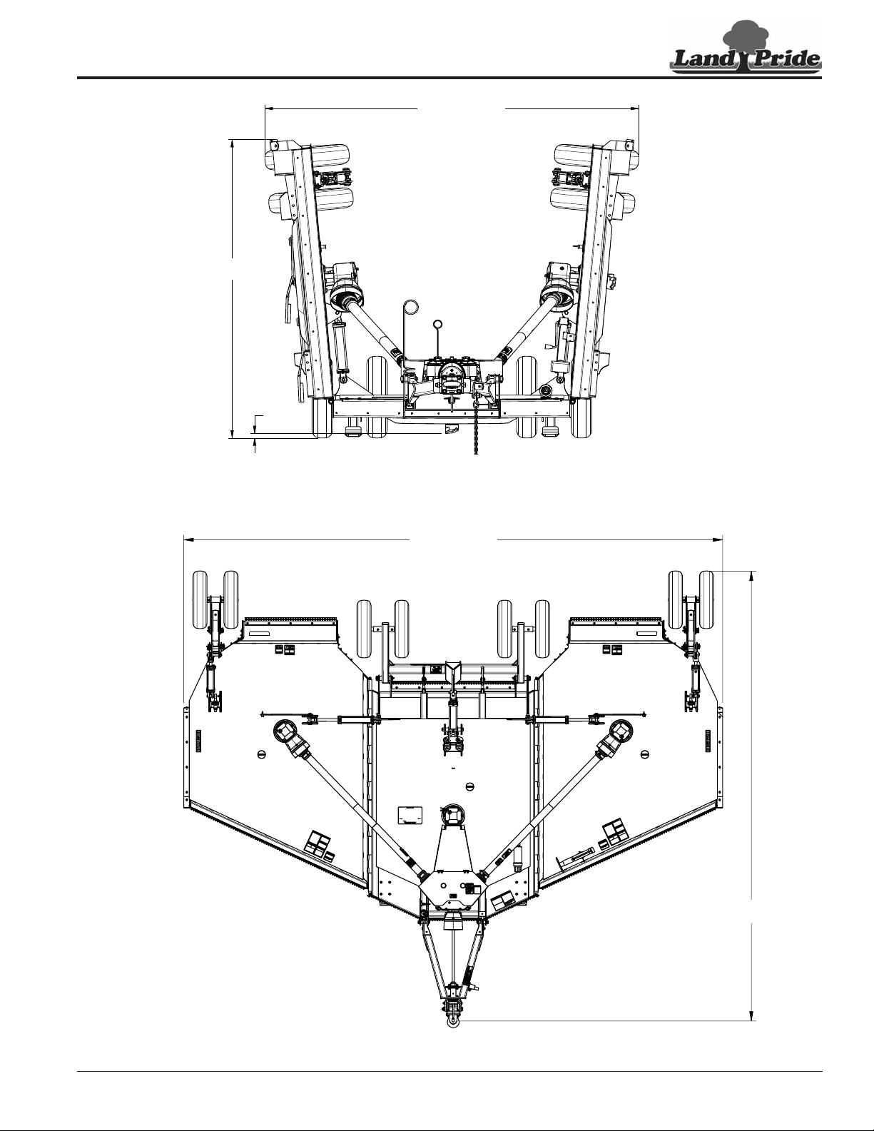
Table of Contents
Section 6: Specifications & Capacities
8' - 3"
2"
9' - 11"
Overall Width With Lift &
Folding Cylinders Fully Retracted
20' -10"
33907
Dimensions Shown Are With Lift Cylinders Fully Retracted.
RC3620 & RCM3620 Rotary Cuters 330-841M9/25/18
17' - 6"
33908
55
Page 60

Table of Contents
Section 7: Features & Benefits
Section 7: Features & Benefits
RC3620 & RCM3620 Models
Features Benefits
Surpassed rugged
industry standards
Factory assembled Saves customer set-up time and money. Adjustments should always be made by dealer.
7 Year gearbox warranty* Shows confidence in gearbox integrity.
250 hp divider gearbox
130 hp center & wing gearboxes
Gearbox Seal Protection Gearbox bottom seal protection for longer bearing life.
2" Output gearbox shaft Large output shaft handles shock loads better.
Input driveline:
Cat. 6 CV or Cat. 5 Conventional
Easy Greasable drivelines Drivelines have access holes for greasing the U-joints and to grease the inner profiles.
2 or 4 Plate slip-clutch
High blade tip speed Allows clean cutting of material & even distribution. See Specifications for actual FPM.
6" Blade overlap Eliminates skipping during turns.
Good cutting capacity Can cut brushy areas with saplings up to 2".
13" Deck height Handles heavy cutting, which reduces balling-up of cut material under the deck.
10 Ga. stump jumper backed with a
1" x 4 1/2" thick blade mounting bar
Spindle Nut Protected
10 gauge smooth deck top Reduces accumulation of debris and is easier and faster to clean.
1/4" side skirt Reduces debris piercing possibilities.
Self-leveling hitch Reduces drawbar wear by keeping hitch level while going through ditches.
Hinged wing sections
1" Solid hinge rods Larger diameter hinge gives greater strength to
Wing transport locks Holds transport wings in the folded-up position in case of hydraulic pressure loss.
Enclosed front to rear dual leveling
rods
5-Bolt hubs 5-Bolt hubs makes the wheel assembly more durable and longer lasting.
Drain holes in wheel rims
Spring-cushioned center axle Protects unit from bumps and ground shock, cushions loads on drawbar.
Replaceable wheel spindles
Rephasing lift cylinders Allows cutter to be leveled using hydraulic cylinders verse mechanical turnbuckles.
7/8" Leveling rods Large diameter leveling rods provide superior supporting strength over rough terrain.
Double swivel hitch option Great for uneven terrain, reduces drawbar wear. Must use spacer washers on drawbar.
LP Performance Hitch option
Bar-tite hitch option Ideal for extreme conditions. Clamps tight to drawbar eliminating drawbar wear.
LED Signal lights
Wheel options
Deck rings (optional) Keeps blades from damaging the deck.
* Years 6 & 7 Parts Only
All Land Pride Cutters have been designed and tested and meet rigorous voluntary
testing procedures.
A rugged heavy-built gearboxes capable of handling heavy-cutting applications.
Holds up to shock loads and harsh mowing conditions.
Protects drivelines and gearboxes by slipping clutches rather than twisting the driveline
when impacts are encountered.
Heavy round stump jumper for protecting the gearbox seal and gearbox output shaft.
Can hold up to tough conditions.
Spindle nut and threads extending beyond the nut are guarded to protect against
damage from hitting solid objects.
Allows cutter to follow terrain. Ideal for rough ground where hillsides, ditches, and
hollows can cause uneven cutting.
cutter and hinge area.
Dual leveling rods enable the cutter to pull equally on the rear axle during travel over
rough terrain. Many competitors only use one leveling rod.
Allows water to drain from wheels mounted on folded-up wings.
Helps prevent paint deterioration and rusting to the wheel rims.
Wheel spindles can be replaced when damaged without replacing the entire axle.
Simply remove one bolt to replace damaged spindle.
Great for uneven terrain, reduces drawbar wear. Hitch pivots freely up and down and
pivots about the tractor drawbar.
LED lights are bright, long lasting, and resistant to vibration, unlike incandescent
counterparts.
Laminated tires: Eliminates flats.
Air-filled tires: Give better cushion while transporting.
Foam-filled tires: Give better cushion while transporting & can’t go flat.
56
RC3620 & RCM3620 Rotary Cuters 330-841M 9/25/18
Page 61

Table of Contents
Section 8: Troubleshooting
Section 8: Troubleshooting
Troubleshooting Chart
Problem Cause Solution
Gearbox overfilled Drain oil level with fill hole or to full mark on dipstick.
Oil seal leaking
Driveline yoke or cross failing
Slip Clutches slip even with a
light load
Bent driveline shaft
(Note: Shaft should be repaired or
replaced if bent)
Driveline shaft
telescoping tube failing
Driveline shaft telescoping tube
wearing
Blades Lock Up
Blades wearing excessively
Blades coming loose
Blades breaking Hitting solid objects Avoid hitting solid objects.
Loose blade carrier
Blade carrier bent Hitting solid objects Avoid hitting solid objects.
Excessive side skid wear
Excessive vibration
Wing cylinder movement too slow Orifice is plugged Remove elbow fitting and unplug orifice.
Seals damaged Replace seals.
Grass or wire wrapped on shaft
in seal area
Clutch is froze
Shock load Avoid hitting solid objects.
Needs lubrication Lubricate every 8 hours.
Scalping the ground Raise cutting height.
Clutch is not properly adjusted
Clutch plates are worn out Replace clutch plates.
Foreign object caught between
clutch plates
Contacting frame Reduce lift height in transport position.
Contacting drawbar Reposition drawbar.
Contacting 3-point arms Raise or remove 3-point arms.
Bottoming out Shorten driveline shaft.
Binding up Not lubricating enough.
Shock load Avoid hitting solid objects.
Needs lubrication Lubricate every 8 hours of operation.
Blades locked together
(overlapped) when wings were
raised to transport position
Tractor has instant on power
take-off
Tractor has Instant off power
take-off
Cutting on sandy ground Raise cutting height.
Contacting ground frequently Raise cutting height.
Power take-off speed too high Maintain power take-off speed by slowing down.
Blades not
tightened properly
Over speeding power take-off Operate cutter at proper power take-off speed.
Blade carrier hardware not
tight
Running loose in the past Replace gearbox bearings and / or shaft.
Soil abrasive Adjust cutter height.
Cutting too low Raise cutting height.
Hitting solid objects Inspect area before cutting. Do not hit solid objects.
Driveline bent Replace driveline or distribution shaft.
Blade carrier bent Replace blade carrier.
Blade broken Replace blade.
Blade will not swing Inspect and unlock blades.
High torque start-up or hitting
solid objects.
Blades have unequal weight Replace each pair of blades on affected carrier.
Clean off wrapped material and check seal areas daily.
Slip clutches per “Run-In” instructions under
“Drivelines With Slip Clutches” on page 43.
Adjust clutch per instructions under “Drivelines With
Slip Clutches” on page 43.
Remove foreign object.
Use pry bar or other tool to separate cutting blades
before lowering wings.
Engage power take-off at low rpms and then slowly
increase engine speed to full power take-off speed.
See Engage Blades on page 35.
Decrease engine speed slowly to an idle and then
disengage power take-off.
See Disengage Blades on page 35.
Tighten blade hardware, refer to
“Maintenance and Lubrication” section starting on
page 41.
Tighten shaft nut to specified torque.
Disassemble and inspect driveline for incorrectly
located needles or damaged bearing cap.
Cutter Blades in the
RC3620 & RCM3620 Rotary Cuters 330-841M9/25/18
57
Page 62
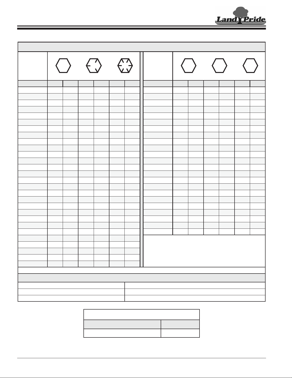
Table of Contents
Section 9: Torque & Tire Inflation Charts
Section 9: Torque & Tire Inflation Charts
Torque Values Chart for Common Bolt Sizes
Bolt Head Identification Bolt Head Identification
5.8
Bolt Size
(inches) Grade 2 Grade 5 Grade 8
1
in-tpi
1/4" - 20 7.45.6 11 81612M 5 X 0.8 436597
1/4" - 28 8.5 6 13 10 18 14 M 6 X 1 7 5 11 8 15 11
5/16" - 18 15 11 24 17 33 25 M 8 X 1.25 17 12 26 19 36 27
5/16" - 24 17 13 26 19 37 27 M 8 X 1 18 13 28 21 39 29
3/8" - 16 27 20 42 31 59 44 M10 X 1.5 33 24 52 39 72 53
3/8" - 24 31 22 47 35 67 49 M10 X 0.75 39 29 61 45 85 62
7/16" - 14 43 32 67 49 95 70 M12 X 1.75 58 42 91 67 125 93
7/16" - 20 49 36 75 55 105 78 M12 X 1.5 60 44 95 70 130 97
1/2" - 13 66 49 105 76 145 105 M12 X 1 90 66 105 77 145 105
1/2" - 20 75 55 115 85 165 120 M14 X 2 92 68 145 105 200 150
9/16" - 12 95 70 150 110 210 155 M14 X 1.5 99 73 155 115 215 160
9/16" - 18 105 79 165 120 235 170 M16 X 2 145 105 225 165 315 230
5/8" - 11 130 97 205 150 285 210 M16 X 1.5 155 115 240 180 335 245
5/8" - 18 150 11 0 230 170 325 240 M18 X 2.5 195 145 310 230 405 300
3/4" - 10 235 170 360 265 510 375 M18 X 1.5 220 165 350 260 485 355
3/4" - 16 260 190 405 295 570 420 M20 X 2.5 280 205 440 325 610 450
7/8" - 9 225 165 585 430 820 605 M20 X 1.5 310 230 650 480 900 665
7/8" - 14 250 185 640 475 905 670 M24 X 3 480 355 760 560 1050 780
1" - 8 340 250 875 645 1230 910 M24 X 2 525 390 830 610 1150 845
1" - 12 370 275 955 705 1350 995 M30 X 3.5 960 705 1510 11 20 2100 1550
1-1/8" - 7 480 355 1080 795 1750 1290 M30 X 2 1060 785 1680 1240 2320 1710
1-1/8" - 12 540 395 1210 890 1960 1440 M36 X 3.5 1730 1270 2650 1950 3660 2700
1-1/4" - 7 680 500 1520 1120 2460 1820 M36 X 2 1880 1380 2960 2190 4100 3220
1-1/4" - 12 750 555 1680 1240 2730 20101 in-tpi = nominal thread diameter in inches-threads per inch
1-3/8" - 6 890 655 1990 1470 3230 23802 N· m = newton-meters
1-3/8" - 12 1010 74 5 2270 1670 3680 27103 ft-lb= foot pounds
1-1/2" - 6 1180 870 2640 1950 4290 31604 mm x pitch = nominal thread diameter in millimeters x thread
1-1/2" - 12 1330 980 2970 2190 4820 3560
Torque tolerance + 0%, -15% of torquing values. Unless otherwise specified use torque values listed above.
N · m 2ft-lb 3N · m ft-lb N · m ft-lb mm x pitch 4N · m ft-lb N · m ft-lb N · m ft-lb
Bolt Size
(Metric) Class 5.8 Class 8.8 Class 10.9
pitch
8.8 10.9
Additional Torque Values
Blade Bolt Locknut 450 ft-lbs
Blade Carrier Hub Nut 550 ft-lbs minimum
Wheel Lug Nuts 85 ft-lbs
Tire Inflation Chart
Tire Size Inflation PSI
29 x 9 - 15 x 16 plys 40
58
RC3620 & RCM3620 Rotary Cuters 330-841M 9/25/18
Page 63

Section 10: Warranty
Section 10: Warranty
be free from defects in material and workmanship beginning on the date of
purchase by the end user according to the following schedule when used as
intended and under normal service and conditions for personal use.
Land Pride and the installation by the dealer of any such replacement part, and
does not cover common wear items. Land Pride reserves the right to inspect any
equipment or parts which are claimed to have been defective in material or
workmanship.
judgment shall have been misused or damaged by accident or lack of normal
maintenance or care, or which has been repaired or altered in a way which
adversely affects its performance or reliability, or which has been used for a
purpose for which the product is not designed. Misuse also specifically includes
failure to properly maintain oil levels, grease points, and driveline shafts.
the product and all warranty adjustments must be made through an authorized
Land Pride dealer. Land Pride reserves the right to make changes in materials or
design of the product at any time without notice.
of any kind, direct, consequential, or contingent to property. Furthermore, Land
Pride shall not be liable for damages resulting from any cause beyond its
reasonable control. This Warranty does not extend to loss of crops, any expense
or loss for labor, supplies, rental machinery or for any other reason.
with respect to this sale; and all implied warranties of merchantability and
fitness for a particular purpose which exceed the obligations set forth in this
written warranty are hereby disclaimed and excluded from this sale.
the date of purchase.
Table of Contents
Warranty
Land Pride warrants to the original purchaser that this Land Pride product will
Overall Unit and Driveline: One year Parts and Labor
Gearbox: 5 Years Parts and Labor; 6th & 7th Year Parts Only
Hydraulic Cylinders: One year Parts and Labor;
Hoses and seals are considered wear items.
Blades, tires and driveline friction discs: Considered wear items
This Warranty is limited to the repair or replacement of any defective part by
This Warranty does not apply to any part or product which in Land Pride’s
Claims under this Warranty should be made to the dealer which originally sold
This Warranty shall not be interpreted to render Land Pride liable for damages
No other warranty of any kind whatsoever, express or implied, is made
This Warranty is not valid unless registered with Land Pride within 30 days from
IMPORTANT: The Online Warranty Registration should be completed by the dealer at the time of
purchase. This information is necessary to provide you with quality customer service.
Model Number ____________________ Serial Number ____________________
RC3620 & RCM3620 Rotary Cuters 330-841M9/25/18
59
Page 64

Corporate Office: P.O. Box 5060
Salina, Kansas 67402-5060 USA
www.landpride.com
 Loading...