

Landoll XO108, XO108-1 User Manual
X-Fold Pulverizer
Models: X108, X108-1, XC108, XC108-1,
XH108, XH108-1, XD108, XD108-1, XO108,
and XO108-1
Widths: 19’, 21’, 23’, 25’, and 27’
Operator's Manual
LANDOLL CORPORATION
1900 North Street
Marysville, Kansas 66508
(785) 562-5381
800-428-5655 ~ WWW.LANDOLL.COM
683rev1113 6J862

6J862683rev501

X108 PULVERIZER
CONTENTS
Introduction ---------------------------------------------------------------------------------------------------------- 3
Location Reference ----------------------------------------------------------------------------------------- 3
Parts Ordering ----------------------------------------------------------------------------------------------- 3
Safety Suggestions ------------------------------------------------------------------------------------------------ 4
Operating Instructions -------------------------------------------------------------------------------------------- 5
Designed Use ------------------------------------------------------------------------------------------------ 5
Tractor Preparation -----------------------------------------------------------------------------------------5
Bleeding Hydraulic Cylinders ---------------------------------------------------------------------------- 5
Field Operation ---------------------------------------------------------------------------------------------- 6
Hitch Adjustment (Used to Limit Soil Pushing) ------------------------------------------------------ 6
Transport ------------------------------------------------------------------------------------------------------ 7
Storing Pulverizer with Drawbar Removed ----------------------------------------------------------- 7
Drawbar Attachment when Pulverizer is Stored ----------------------------------------------------- 7
Maintenance -------------------------------------------------------------------------------------------------------- 8
Fasteners ----------------------------------------------------------------------------------------------------- 8
Tires for Single Wheel Pulverizers (Standard) ------------------------------------------------------- 8
Tires for Dual Wheel Pulverizers (Optional) ---------------------------------------------------------- 8
Lubrication ---------------------------------------------------------------------------------------------------- 8
Shipping Bundles -------------------------------------------------------------------------------------------------- 9
Setting Up Instructions ----------------------------------------------------------------------------------------- 10
Wheel and Pipe Shaft Assembly ---------------------------------------------------------------------- 10
Frame Setup ----------------------------------------------------------------------------------------------- 13
Warning Lights LED's ----------------------------------------------------------------------------------- 17A
Specifications ----------------------------------------------------------------------------------------------------- 18
Scraper Installation ---------------------------------------------------------------------------------------------- 20
Page I
6J862683rev0713

6J862683rev501
INTRODUCTION
Your Brillion Pulverizer is built with the best materials and workmanship available. It has been designed to
give years of trouble-free operation. Proper care and operation will insure that you receive the service and
long life built into this machine.
Study this manual carefully before attempting to assemble or operate the machine. A special section, “Setting
Up Instructions”, is included.
This safety alert symbol is used to call your attention to instructions concerning
personal safety. Federal law requires you to explain the safety and operating
instructions furnished with this machine to each employee before they are allowed
to operate the machine. These must be repeated to the employee at the start of
each season. Be sure to observe and follow the instructions for the safety of
anyone operating or near the machine.
Location Reference
Right hand, left hand, forward and rear refer to operator’s right, left, front and rear when he faces the same
direction as the machine will travel in the f eld.
Parts Ordering
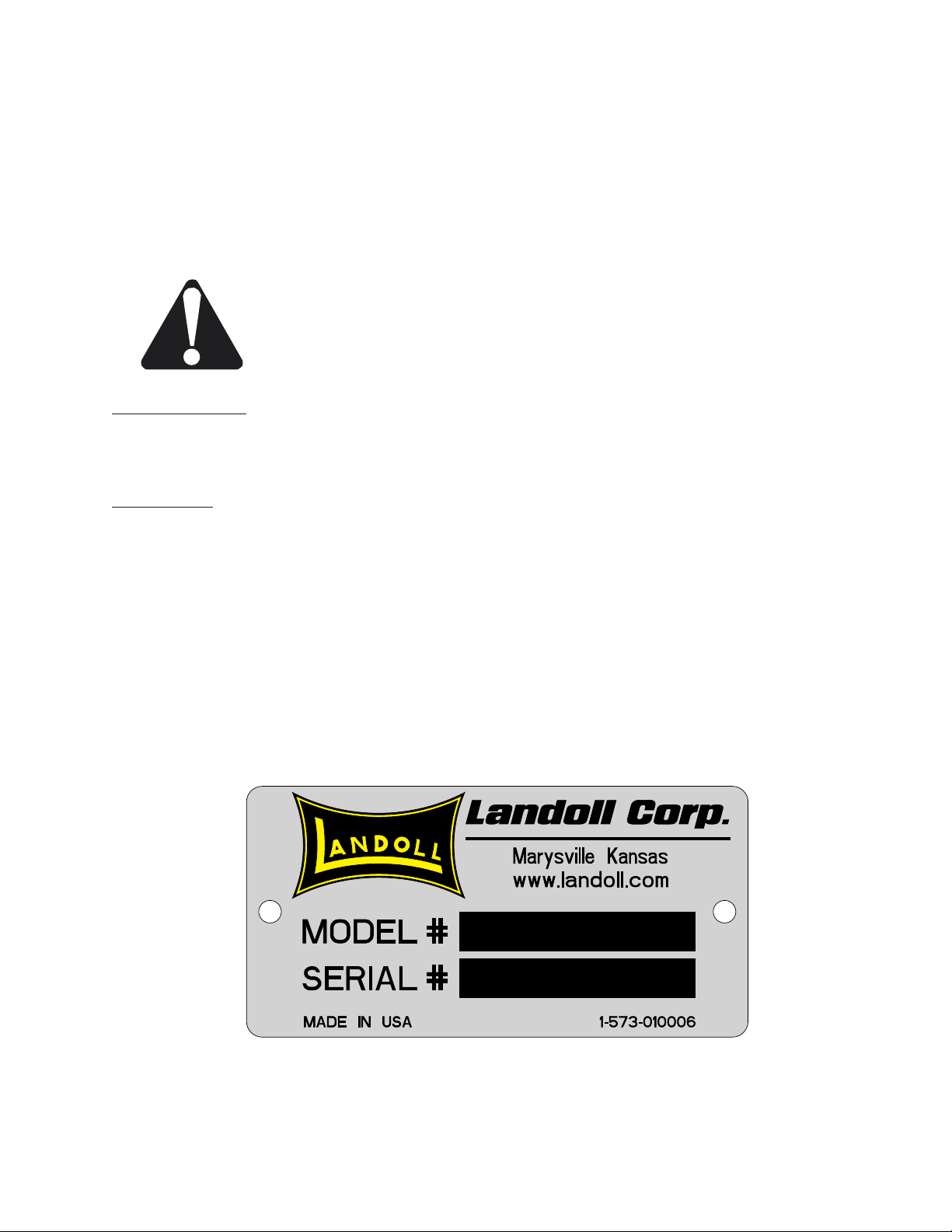
When ordering parts for this machine, include the complete model number and serial number. Refer to the
name plate on the angled tube above the drawbar, left side, center section of the machine as indicated in the
diagram below. Please record these numbers upon taking delivery of the unit.
Pulverizer Model No.________________
Serial No._________________________
Date Purchased____________________
Be sure to read the warranty card which is shipped with the machine. Return the proper portion of the card
for recording at the factory.
Page 3
6J862683rev501

SAFETY SUGGESTIONS
Federal law requires you to explain the safety and operating instructions furnished with this machine
to all employees before they are allowed to operate the machine. These must be repeated to the employees at the beginning of each season. Be sure to observe and follow the instructions for the safety
of anyone operating or near the machine.
Investigation has shown that nearly one-third of all farm accidents are caused by careless use of machinery. You can do your part in improving safety by observing the following suggestions. Insist that
all people working with you or for you abide by them.
1. Do not stand between the tractor and implement when attaching or detaching implement unless both are not moving.
2. Do not make adjustments or lubricate machine while it is in motion.
3. Do not allow anyone to ride on tractor or machine.
4. Always use transport lock when transporting machine.
5. Do not transport at speeds over 20 mph.
6. Avoid sudden stops or turns when transporting because weight of machine may cause operator to lose control of tractor. Use a tractor heavier than machine. Do not allow tractor drawbar
to swing when transporting.
7. Use caution when towing behind articulated steering tractors; fast or sharp turns may cause
the machine to slip sideways.
8. When transporting the machine on a road or highway, use adequate warning symbols, reflec-
tors, lights, and slow moving vehicle signs as required.
9. Lower machine to ground when not in use.
10. Block machine so it will not roll when unhitched from tractor.
11. Relieve pressure in hydraulic lines before uncoupling hydraulic hoses from tractor. On most
tractors this can be done by operating valves after engine is stopped.
12. Securely block machine when working on or under it to prevent injury in case of hydraulic
failure or inadvertent lowering by another person.
13. Do not allow anyone near the machine when folding or unfolding the wings.
14. Fold wings on as level a surface as possible.
15. Install safety chain between the pulverizer and the tractor. See page 19 of this manual and/or
tractor manual.
16. Escaping hydraulic fluid under pressure can have sufficient force to penetrate the skin,
causing serious personal injury. Before applying pressure to the system, be sure all
connections are tight and that lines and hoses are not damaged.
17. Hydraulic fluid escaping from a very small hole can be almost invisible. Use a piece of
cardboard or a piece of wood, rather than hands, to search for suspected leaks.
Page 4
6J862683rev501
Safety Signs & Decals
528933
528934
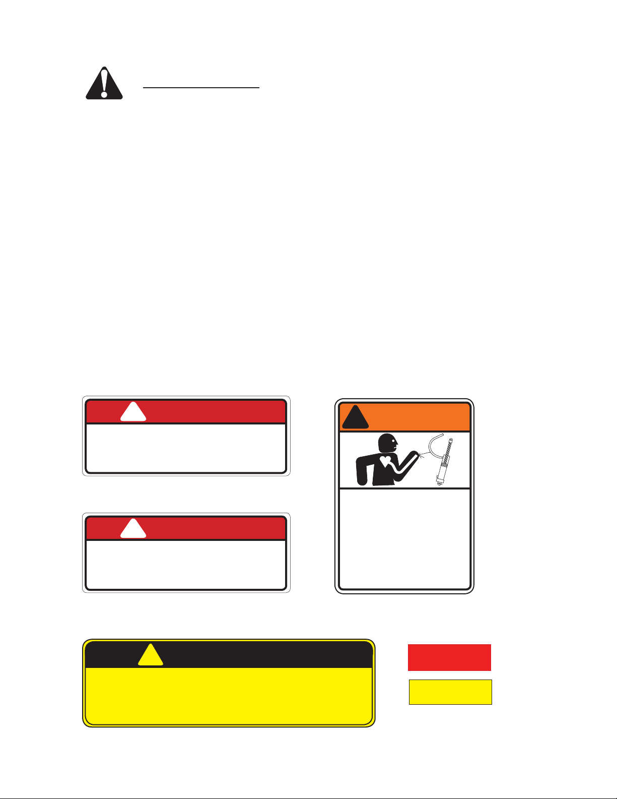
There are three levels of hazard intensity that appear with the safety alert symbol on safety decals: DAN-
GER, WARNING, and CAUTION. The level of hazard intensity is determined by the following definitions:
DANGER - Immediate hazards which WILL result in severe personal injury or death.
WARNING - Hazards or unsafe practices which COULD result in severe personal injury or death.
CAUTION - A reminder of safety practices, or an alert to unsafe practices which could result in
personal injury.
Examine safety decals and be sure you have the correct safety decals for the machine. Keep these signs
clean so they can be observed readily. It is important to keep these decals cleaned more frequently than the
machine. Wash with soap and water or cleaning solution as required.
Replace decals that become damaged or lost.
Order decals through your BRILLION dealer.
When applying decals to the machine, be sure to clean the surface to remove any dirt or residue. Where possible, sign placement should protect the sign from abrasion, damage, or obstruction from mud, dirty oil, etc.
These are the safety decals provided for the pulverizer. (Their locations are illustrated on the next page).
3J675
!
DANGER
!
FALLING WINGS CAN CAUSE INJURY
OR DEATH. STAND CLEAR WHEN WINGS
ARE BEING RAISED OR LOWERED.
!
BLEED THE AIR FROM WING LIFT CYLINDERS
BEFORE OPERATING. FAILURE TO DO SO WILL
ALLOW WINGS TO FREE-FALL AND MAY CAUSE
SERIOUS PERSONAL INJURY. SEE OPERATOR’S
MANUAL FOR CORRECT PROCEDURE.
DANGER
3J675
3J678
3J678
DO NOT GO NEAR LEAKS
HIGH PRESSURE OIL EASILY PUNCTURES
CAUSING SERIOUS INJURY, GANGRENE
OR DEATH.
IF INJURED, SEEK EMERGENCY MEDICAL
IMMEDIATE SURGERY IS REQUIRED TO
REMOVE OIL.
DO NOT USE FINGERS OR SKIN TO
CHECK FOR LEAKS.
LOWER LOAD OR RELIEVE HYDRAULIC
PRESSURE BEFORE LOOSENING
FITTINGS.
5J859
!
1. DO NOT ALLOW ANYONE TO RIDE ON THIS IMPLEMENT.
2. DO NOT TRANSPORT AT SPEEDS OVER 20 MPH.
3. DO NOT STAND BETWEEN TRACTOR AND IMPLEMENT WHILE TRACTOR IS MOVING.
4. WHEN SERVICING IN RAISED POSITION, PLACE BLOCKING UNDER ROLLERS.
5. WITH WINGS FOLDED AND WEIGHT ON CENTER ROLLER, THE IMPLEMENT IS
DRAWBAR LIGHT.
CAUTION
5J859
WARNING
3K706
SKIN
HELP.
10813A
Page 4A
6J862683rev501
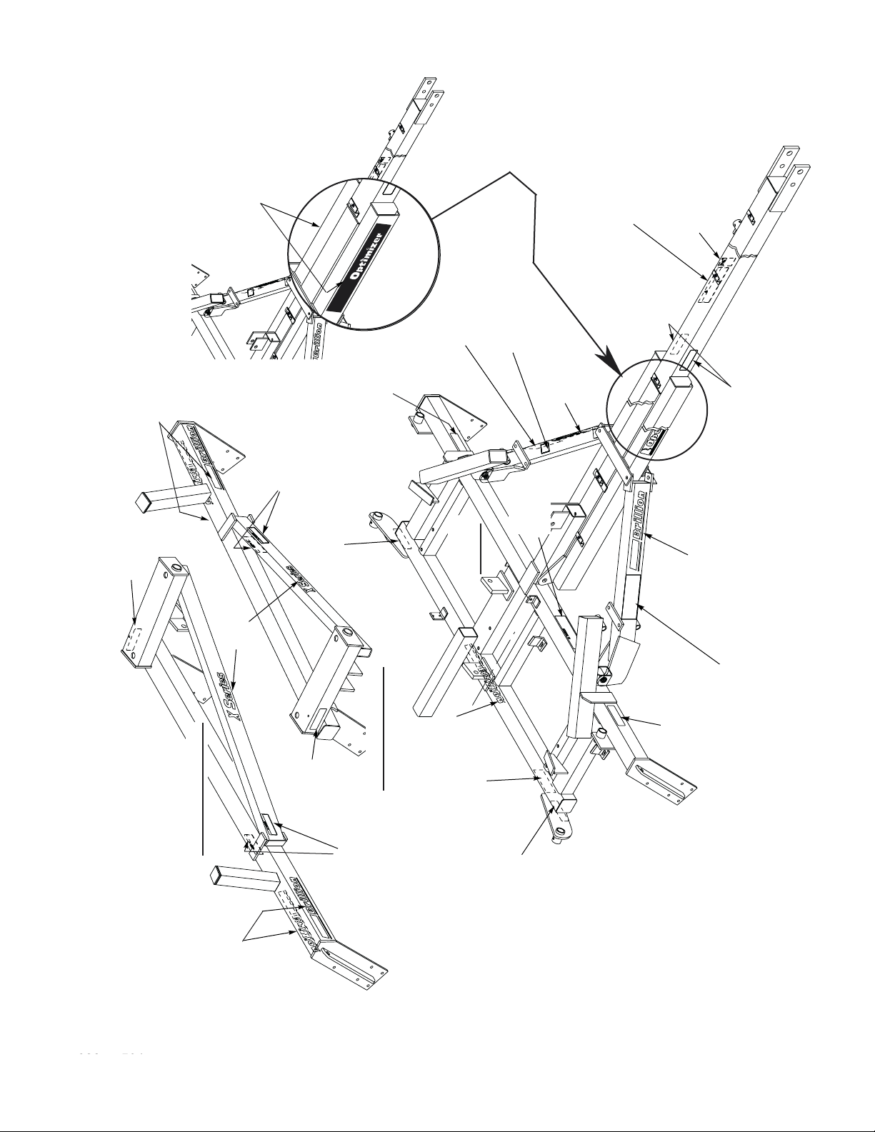
4K036
528934
AMBER
6K657
OPTIMIZER
(Both Sides)
ADDITIONAL DECAL ON
OPTIMIZER MODEL
PULVERIZERS ONLY:
BRILLION
(Back &
Front Where
Fit Allows)
3J675
DANGER-FALLING
WINGS
(Front & Back)
528933
528934
RED
AMBER RE-
FLECTIVE
6J999
PULVERIZER FIELD
ADJUSTMENTS
8D387
CENTER
FRAME
PATENT
3J678
DANGER
4K036
BRILLION
BLEED AIR
5J859 - CAUTION
DO NOT ALLOW...
3K706 - DANGER
4K036
HYDRAULIC LEAKS
528934
AMBER REFLECTIVE
BRILLION
(Both Braces)
LOCATIONS
DECAL
PULVERIZER
4K036
BRILLION
4K156
X SERIES
528934
AMBER
RIGHT HAND WING
(Back &
Front w here
Fit Allows)
3J675
DANGER
FALLING WINGS
(Front & Back)
4K036
BRILLION
LEFT HAND WING
3J675
DANGER
FALLING WINGS
528933
REFLECTIVE
RED
528934
AMBER
6J999
PULVERIZER
FIELD
ADJUSTMENTS
500
Page 4B
6J862683rev501

OPERATING INSTRUCTIONS
Designed Use
The folding pulverizer is designed to pull behind wide model f eld cultivators and discs. It can be used as an
individual unit with the tractor to prepare a seedbed or after seeding to breakdown and pulverizer large surface clods. The long drawbar allows for easy, short turns when pulled behind other equipment.
Tractor Preparation
Lock tractor drawbar in center position. Do not allow the drawbar to swing, especially during
transport.
Pulverizer Preparation
Hydraulic oil capacity of pulverizer is approximately 2.0 gallons.
Clean hose fitting before connecting to tractor. It is also necessary during initial operation to watch tractor oil
level closely to avoid damage.
In feld working position with the three cylinders at the end of their stroke the wing gang will be able to f oat
which allows them to follow the ground contour. At the same time the axle tires will be raised 4 inches off the
ground to avoid making tire tracks on the pulverized field.
Bleeding Hydraulic Cylinders
CAUTION: Escaping hydraulic f uid under pressure can have suff cient force to
penetrate the skin, causing serious personal injury. Relieve pressure in hydraulic lines
before uncoupling hydraulic hoses from tractor. On most tractors this can be done by
operating valves after engine is stopped. Before applying pressure to the system, be
sure all connections are tight and that lines and hoses are not damaged.
Hydraulic fuid escaping from a very small hole can be almost invisible. Use a piece of cardboard or a
piece of wood, rather than hands, to search for suspected leaks.
l
If injured by escaping fluid, see a doctor at once. Serious infection or reaction can develop if proper
medical treatment is not administered immediately.
Bleed the air from the hydraulic system before moving the machine. Bleed the air from the transport system
frst. This can be done by partially raising and lowering the machine slowly 5 or 6 times. Gradually increase
the length of stroke until the last two cycles are the full stroke on the cylinder.
Bleed the air from the wing folding system next. Raise center of machine, then push transport lock down.
Tighten the 1” nut in the transport cylinder anchor to hold the center up. For machines with manual transport
lock place or remove transport lock on hydraulic cylinder instead of tightening or loosening 1” nut. If the wings
are unfolded, begin partially folding them and then unfolding t hem again. When unfolding hold the tractor
valve to get the most oil in that side of the cylinder. Be careful that neither wing goes over 90°. Repeat this
process 8 or 9 times gradually raising the wings closer to 90°. After bleeding procedure is complete loosen 1”
nut in the transport cylinder anchor to allow free movement.
If the wings were folded to start with, use the same procedures except start unfolding at the wings and then
re-fold them.
If it becomes necessary to drain the oil from one or more cylinder, it is important to bleed the air out of the
system before operating.
Change the machine from field position to transport position 2 to 3 times to insure the automatic transport lock
is functioning properly.
Page 5
6J862683rev501
Field Operation
Once the folding pulverizer has been transported to the field, unfold the wings completely. Reversing the hydraulic
level should allow the pair of compression springs to push transport lock up with automatic transport lock. After
this the implenent may be completely lowered. With manual transport lock reverse the hydraulic lever to allow
manual removal of cylinder transport lock.
During field operation, it is not necessary to raise the machine for turns, but turns should be as wide as possible.
Slow down when operating on rocky soil.
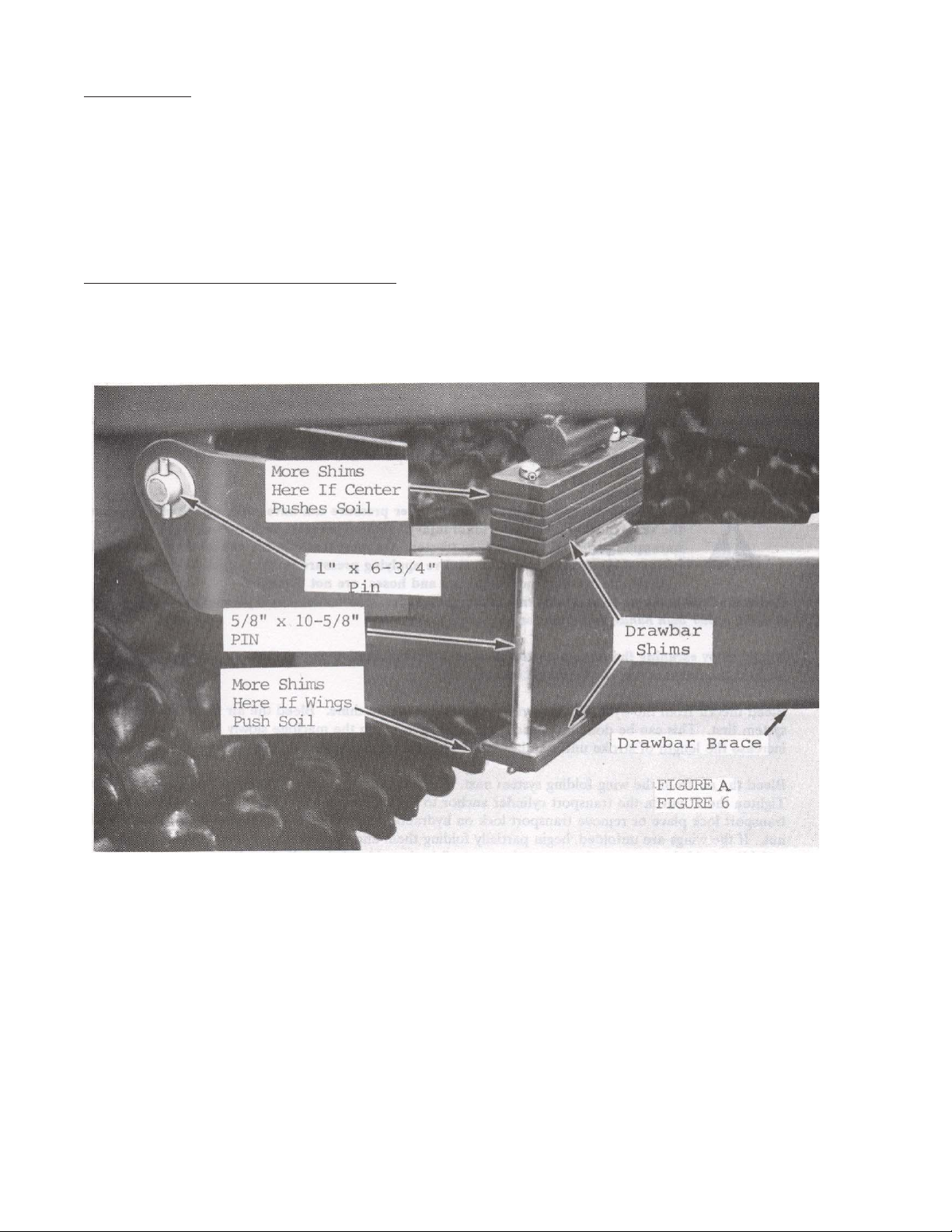
Hitch Adjustment (Used to Limit Soil Pushing)
The pulverizer drawbar can pivot vertically in field operation. The placenent of shims must be identical on both
sides of pulverizer. See figure below for position of drawbar shims.
If the pulverizer continues to push soil, a 6J-194 manual valve kit can be added to hold the wings up at a preset
height. See setup instructions for installation. Raise wings to the desired height with tractor hydraulics and shut off
the valve. This allows some weight of the pulverizer wings to be transferred to the transport wheels, without the
hydraulic system raising the wings. With the tractor hydraulics being used to raise or lower the pulverizer the outside end of the wings and the center frame will all raise or lower uniformly the same distance. The valve will have
to be opened to fold wings. When center section is raised slightly tire tracks of pulverizer will be left in the field.
Wing can float up with valve closed.
Page 6
6J862683rev501

Transport (With Automatic Lock Models)
Fold the wings for transport. In transport relieve the hydraulic pressure until the cylinder transport lock is tight
against pin in the lift arm. There should be no need to do anything with pulverizer when going from field to
transport or transport to field.
Storing Pulverizer With Drawbar Removed
Start with pulverizer in field position. It may be necessary to move some additional drawbar shims to the bot-
tom side of the drawbar braces. Install the storage cylinder lockout which is 5-1/4” long that is attached to a
hydraulic hose on the center cylinder. Fold the wings with the cylinder transport lock up, with 1” nut on center
cylinder anchor bolt tightened. Position pulverizer with tractor where it will be stored. Relieve the hydraulic
pressure until the storage cylinder lockout is tight against the end of the cylinder barrel. Remove hydraulic
line brackets from the drawbar next. It is not necessary to break any hydraulic lines. Rest the hydraulic lines
on the center frame. The drawbar braces and drawbar can now be removed.
Drawbar Attachment When Pulverizer Is Stored
Attach the drawbar and drawbar braces. Next assemble hydraulic lines to the drawbar. Refer to setup instructions. Hitch tractor to drawbar. Raise center section and remove pulverizer from storage. Next unfold
wings completely then raise center section completely. Remove storage cylinder lockout and loosen 1” nut on
center cylinder anchor bolt slightly to allow free movement of transport lock.
Figure 2
Page 7
6J862683rev501

MAINTENANCE
Fasteners
After a few hours of use check entire machine and tighten any loose nuts or bolts. Daily or periodic checks
should be made thereafter.
Tires For Dual Wheel Pulverizers
Recommended size of four tires are: 9.5L x 15 6 ply inflated to 24 psi
Lubrication
Grease zerk fittings daily. Locations are:
Transport axle bearings (bottom) ------------------- 3
Hinge pins ------------------------------------------------ 4 (2 per hinge)
The above items are not sealed and cannot be overgreased.
Wheel bearings should be repacked annually.
When Pulverizer is not used for some time, exposed cylinder rods should be cleaned and covered with a thick
coat of grease. This will prevent corrosion which will damage seals.
Page 8
6J862683rev501
 Loading...