


 Loading...
1
111 Canfield Avenue • Randolph, New Jersey 07869 • 1-800-LANDICE • FAX 973-927-0630
8700-Series
Home and Commercial Treadmill Diagnostic and Service Manual 2001
This guide covers all 8700 series treadmills manufactured from 1993 – 2000.
HOME TREADMILLS – 8700 SPRINT 1-4 / PRG / SST
NOTE: Early HOME treadmills listed as: 8700R & 8700P are the same as the LTD models. The only difference was the warranty coverage.
LTD / 110V UNITS – 8700R (REGILAR NO PROGRAMS) / P (WITH PROGRAMS) / PT1 / PT2
CLUB / 220V UNITS – 8700R (REGILAR NO PROGRAMS) / P (WITH PROGRAMS) / PT1 / PT2
Version M/C.1
For Technical Service Call 1-(800)-LANDICE
2
Service Manual Ver M/C.1
Page 2 Table of Contents
SECTION 1- Introduction
Page 3 How to use this manual
Page 4-5 Landice warranty and policy
Page 6 Tools needed for repairs
SECTION 2- Installation
Page 7-9 Safety warnings
Page 10-13 Membrane panel identification
SECTION 3- - Parts Identification
Page 14-16 |
Parts listing |
Page 17 |
Commercial motor pan picture |
Page 18 |
Commercial (LTD / CLUB) motor pan lower wiring schematic |
Page 19-20 LED lights / SCR lower board |
|
Page 21 |
Home motor pan picture |
Page 22 |
Home motor pan wiring schematic |
Page 23 |
LED lights / PWM board |
Page 24 |
LED lights / RELAY board |
Page 25 |
SST, PRG, SPRINT-3 (Open Loop); lower wiring schematic |
Page 26 |
SPRINT – 2; lower wiring schematic |
Page 27 |
SPRINT – 1; lower wiring schematic |
Page 28 |
SPRINT – 1&2; upper wiring schematic |
SECTION 4 –Servicing Landice Treadmills
Page 29-31 Definitions of components Page 32-34 Testing components
Page 35-37 Common symptoms
Page 38 Calibrating speed potentiometers
Page 39-45 Removal and replacement of components Page 46-48 Noises
Page 49 Voltage checks
Page 50 Diagnostics and error codes
Page 51-59 8700 LTD / CLUB diagnostic flow charts
Page 60-65 8700 HOME (Closed Loop / SPRINT-4, SST, PRG) diagnostic flow charts Page 66-68 SPRINT –3 Diagnostics
Page 69-75 SPRINT –2 Diagnostics
Page 76-77 Tracking and Tensioning Page 78-79 Treadmill maintenance
Page 80-84 Index
3
How to Use this Manual
This manual is designed to help service technicians in the installation, maintenance, or repair of
Landice 8700 model treadmills. It covers terminology, installation, tools needed, diagnostics, removal and replacement of parts, estimated time of repairs, warranty forms, wiring schematics, and recommended maintenance. If you find a problem not covered in this manual please call 1-800- LANDICE to talk to a Landice Service Technician.
4
Landice Warranty and Policies
PARTS
Our policy requires that all defective parts be returned to Landice. All warranty parts will be billed to the dealer at dealer cost. Landice will credit this invoice upon receipt of defective parts. Landice will pay the freight to send out any defective parts. It is the dealer's responsibility to pay the freight to return the defective parts to Landice. If the defective parts are not returned within 30 days, payment of invoice is expected in full.
LABOR
Landice will reimburse the selling dealer according to our flat rate labor schedule. If you are a service provider for Landice and do not sell our product, you have the option of billing us direct or you can bill the dealer your providing service for. Generally, if our capped rate does not cover your labor charge you would bill the selling dealer. The current rate is $30.00 per hour and is capped at a maximum of one hour labor and one hour travel per treadmill failure. Diagnostic
and return trips are not covered. Note that treadbelt tracking, treadbelt/drivebelt tensioning, blown fuses, and set-up procedures are not covered by this warranty. Set-Up Includes: Assembly, adjusting treadbelt and drive belt (if needed), walking the treadbelt and deck wax in and performing any additional adjustments that may have been upset during shipping.
The dealer must call for a service authorization number prior to performing any service to verify the treadmill is under labor warranty. It is advisable to call Landice from the treadmill location to successfully diagnose the problem. This will ensure that the correct part will be shipped out the first time. Labor claim forms must be submitted within three months from the date service was performed. Labor claim forms must be completely filled out and have the Landice authorization number at the top.
FLOOR MODELS
The following warranty applies to floor models and dealer stock.
If the dealer sells a treadmill to a customer within one year of its purchase from Landice, the warranty period will be extended to start from the date of sale to the customer.
If a treadmill is over 1 year old when sold to a customer, the remainder of the parts warranty will be honored from the date of shipment and 1 year labor.

5
September 1, 2001
Treadmill Warranty Summary
Landice Factory Warranty Summary
Home Treadmills
07-15-1998 |
Lifetime Frame |
5 Year Parts |
1 Year Labor |
07-15-1996 |
Lifetime Frame |
3 Year Parts |
1 Year Labor |
07-15-1993 |
Lifetime Frame |
2 Year Parts |
1 Year Labor |
8700LTD Limited Institutional Use Treadmills (120VAC)
(In applications with under 5 hours usage per day)
09-01-1996 |
3 |
Years Parts |
1 Year Labor |
09-01-1993 |
1 |
Year Parts |
1 Year Labor |
8700 CLUB Treadmills (220VAC)
|
(Scheduled maintenance required) |
||
11-15-1996 |
3 |
Years Parts |
1 Year Labor |
11-15-1993 |
1 |
Year Parts |
1 Year Labor |
TREADMILL PARTS
All defective parts must be delivered to Landice (freight prepaid) where they will either be repaired or replaced at Landice's discretion. This warranty does not cover cosmetic damage, damage due to acts of God, accident, misuse, abuse, improper maintenance, or negligence to the product. This warranty does cover normal wear and tear. This warranty is valid only in the United States and Canada.
SERVICE LABOR
For a period of 1 year, Landice will reimburse the selling dealer according to the terms, rates and conditions in effect at the time of service. A service authorization number must be obtained prior to performing service in order to qualify for service reimbursement. This service warranty does not cover customer instruction, installation, setup, or adjustments. Note that treadbelt tensioning and tracking is the responsibility of the user and is not covered by this warranty. Instructions for treadbelt tensioning and tracking are located in the owner's manual. This warranty is valid only in the United States and Canada.
6
Recommended tools for servicing Landice treadmills
1.Deep socket set 3/8 drive with ratchet and extension: Must have 3/8, 7/16, 1 /2, 5/16, 9/16 socket.
2.Combination wrench set: Must have 3/8, 7/16, 1 /2, 5/16, 9/16
3.#1, 2, and 3 Philips head screwdriver (or electric screwdriver)
4.#1, 2, and 3 flat head screwdriver (or electric screwdriver)
5.Socket head cap screw wrench set/ multi Allen Wrench
6.Rubber mallet
7.Diagonal cutting pliers
8.Wire stripper
9.Wire crimping tool
10.Digital voltmeter (We recommend Radio Shack Pocket Digital Voltmeter). Analog voltmeters are not recommended.
11.Utility knife
12.Pulse simulator
7
Important Operating Safety Instructions
WARNING: Failure to observe the following operating instructions can result in serious injury!
1If you are suffering from any illness, condition, or disability which affects your ability to run, walk or exercise, do not use this product without consulting your doctor first.
2If you are suffering from any illness, condition, or disability which affects your ability to run, walk or exercise, do not use this product without supervision present. Failure to do so can result in serious injury should you fall while the treadbelt is moving.
3Failure to leave ample clearance around the treadmill could result in the user becoming trapped between the treadmill and a wall, resulting in burns or other serious injury from the moving treadbelt.
Allow a minimum clearance of 18 inches on each side of the treadmill.
Allow a minimum clearance of 4 feet at the rear of the treadmill.
4Never stand on the treadbelt when starting the treadmill. A sudden start could cause you to lose your balance. Always stand with one foot on each side rail until the belt starts moving.
5Always wear the emergency stop safety strap securely around your wrist while exercising. Failure to do so can result in severe injuries should you accidentally fall while exercising.
6Test the emergency stop safety key on a regular basis by pulling on the cord and ensuring that the treadbelt comes to a complete stop.
7Always remove the safety key from the treadmill when you are through exercising, especially if children are present. This will prevent them from accidentally starting the treadmill.
8Be sure to familiarize yourself with the owner manual. Look it over carefully. Be sure you understand the control panel operation before using the treadmill.
8
DANGER
To reduce the risk of electric shock, always unplug the treadmill from the electrical outlet immediately after using. Always unplug the treadmill before cleaning or removing the motor cover.
WARNING
To reduce the risk of burns, fire, electric shock, or injury to persons:
1Treadmill should never be left unattended when plugged in. Unplug from outlet when not in use.
2Close supervision is necessary when this unit is used by or near children or disabled persons.
3Use this treadmill only for its intended use as described in this manual.
4Do not operate this treadmill if it has a damaged cord or plug, if it is not working properly or if it has been damaged. Call your selling dealer immediately for examination and repair.
5Keep the power cord away from heated surfaces. Be sure the line cord has plenty of slack and does not get pinched underneath the treadmill when it elevates and lowers. If an extension cord must be used do not use one longer than 6 feet with 12 gauge wire.
6Never operate the treadmill with the air openings blocked. Keep the air openings free of lint, hair, and the like.
7Never drop or insert any object into any opening. Be sure no objects are near or underneath the moving treadbelt when using the treadmill.
8Do not use outdoors.
9Do not operate where aerosol spray products are being used or where oxygen is being administered.
10Connect this appliance to a properly grounded outlet only. Do not use a GFI outlet.
11To disconnect, press the OFF button, remove the SAFETY LANYARD, and unplug the unit from the wall outlet.
GROUNDING INSTRUCTIONS
This product must be grounded. If it should malfunction or break down, grounding provides a path of least resistance for electric current to reduce risk of electric shock. This product is equipped with a cord having an equipment-grounding conductor and a grounding plug. The plug must be plugged into an outlet that is properly installed and grounded in accordance with all local codes and ordinances. We do not recommend using a GFI outlet.
120 Volt Treadmills (15 Amp dedicated line)
Treadmills marked 120 VAC are intended for use in a nominal 120-volt circuit with a grounding plug. Make sure the product is connected to an outlet having the same configuration as the plug. No adapter should be used with this product.
9
200 - 250 Volt Treadmills (15 Amp dedicated line)
Treadmills marked 200-250 VAC are intended for use on a circuit having a nominal rating more than 120V and are factory-equipped with a specific cord and plug to permit connection to a proper electric circuit. Make sure the product is connected to an outlet having the same configuration as the plug. No adapter should be used with this product. If the product must be reconnected for use on a different type of electric circuit, the reconnection should be made by qualified service personnel.
DANGER! Improper connection of the equipment-grounding connector can result in a risk of electric shock. Check with a qualified electrician or serviceman if you are in doubt as to whether the product is properly grounded. Do not modify the plug provided with the product. If it will not fit in the outlet, have a proper outlet installed by a qualified electrician.
10
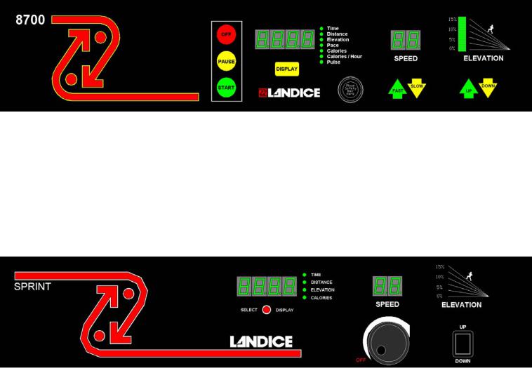
8700 Standard Membrane
Models That Used This Membrane: 8700, 8700-R, 8700-LTD, 8700-LTD-VFX,
8700-CLUB, 8700-CLUB-VFX
Production Time Frame: 1991-1999
Electronics: Standard 110V SCR (220V SCR for CLUB units), commercial motor pan.
See Wiring Diagram.
Settings Used In: Home and Commercial (LTD’s and CLUB’s)
Key Features: Closed Loop Treadmill (w/ speed sensor), Safety Lanyard, 0.5-11MPH Push Button
Speed and Elevation Control
8700 Sprint Membrane
Models That Used This Membrane: 8700 Sprint-1, 8700 Sprint-2
Production Time Frame: Sprint-1 1991-1995, Sprint-2 1995-1996 Electronics: 110V Unit, See Wiring Diagrams for 8700 Sprint-1 and Sprint-2
Settings Used In: Home
Key Features: Open Loop Treadmill (w/o speed sensor), Safety Lanyard on Sprint-2 only, 1.0-
9.0MPH Rheostat Speed Control, Rocker Switch Elevation Control.
11
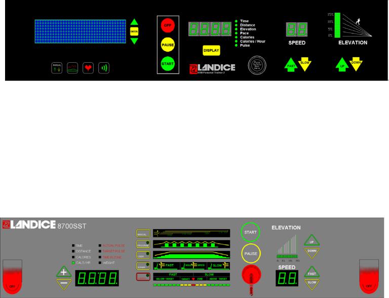
8700 EP/PT Membrane
Models That Used This Membrane: 8700EP, 8700-PT
Production Time Frame: 1991-1993
Electronics: Standard 110V SCR (220V SCR for CLUB units), commercial motor pan. See Wiring Diagram.
Settings Used In: Home and Commercial
Key Features: Closed Loop Treadmill (w/ Speed sensor) Safety Lanyard, 0.5-11.0MPH Push Button
Speed and Elevation Control, 10 Built In Programs, 4 User Programs, Wireless Heart Rate Control
(Optional), LED Graphic Display.
8700 P Membrane
Models That Used This Membrane: 8700-P, 8700-LTD-P, 8700-CLUB-P
Production Time Frame: 1991-1999
Electronics: Standard 110V SCR (220V SCR for CLUB units), commercial motor pan.
See Wiring Diagram.
Settings Used In: Home and Commercial (LTD’s and CLUB’s)
Key Features: Closed Loop Treadmill (w/ speed sensor), Safety Lanyard, 0.5-11MPH Push Button Speed and Elevation Control, 5 Built In Programs.
12
8700 PT2 Membrane
Models That Used This Membrane: 8700-PT2, 8700-CLUB-PT2
Production Time Frame: 1994-1998
Electronics: Standard 110V SCR (220V SCR for CLUB units), commercial motor pan.
See Wiring Diagram.
Settings Used In: Home and Commercial
Key Features: Closed Loop Treadmill (w/ Speed sensor) Safety Lanyard, 0.5-11.0MPH Push Button Speed and Elevation Control, 9 Built In Programs, 4 User Programs, Wireless Heart Rate Control,
SONAR ranging capability (Optional), LED Graphic Display.
8700 SST Membrane
Models That Used This Membrane: 8700-SST, 8700-SST-VFX
Production Time Frame: 1995-1999
Electronics: 8700-SST used Sprint-3 electronics, 8700-SST-VFX used Sprint-4 electronics, See Wiring Diagrams.
Settings Used In: Home
Key Features: 8700-SST Open Loop Treadmill (w/o speed sensor), 8700-SST-VFX Closed Loop Treadmill (w/ Speed sensor) Safety Lanyard, 0.5-12.0MPH Push Button Speed and Elevation Control.
5 Built In Programs, 5 User Programs, Wireless Heart Rate Control, SONAR ranging capability.
13
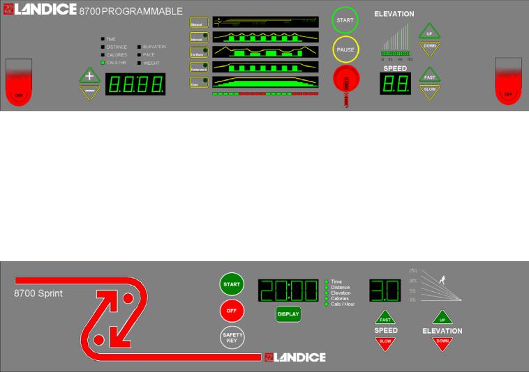
8700 Programmable Membrane
Models That Used This Membrane: 8700-PRG, 8700-PRG-VFX, 8700-CLUB-PRG
Production Time Frame: 1996-1999
Electronics: 8700-PRG used Sprint-3 electronics, 8700-PRG-VFX used Sprint-4 electronics, 8700-CLUB-PRG used 220V PWM commercial motor pan. See Wiring Diagrams.
Settings Used In: Home and Commercial (LTD’s and CLUB’s)
Key Features: Closed Loop Treadmill (w/ speed sensor), Safety Lanyard, 0.5-12MPH Push Button Speed and Elevation Control, 4 Built In Programs, 2 User Programs.
8700 Sprint Faceplate
Models That Used This Faceplate: 8700 Sprint-3, 8700 Sprint-4, 8700-Sprint-4-VFX
Production Time Frame: Sprint-3 1997-1998, Sprint-4 1998-1999 Electronics: 110V Unit, See Wiring Diagrams for 8700 Sprint-3 and Sprint-4
Settings Used In: Home
Key Features: Sprint-3 Open Loop Treadmill (w/o speed sensor), Sprint-4 Closed Loop Treadmill (w/
Speed sensor) Safety Lanyard, 0.5-12.0MPH Push Button Speed and Elevation Control.

14
Section 3 – Parts Identification
M odel8700 Treadm illParts
Item |
Part# |
M SRP |
N ote |
Treadbelt |
70046 |
$326.00 |
|
Treadbelt-XL |
70157 |
$381.00 |
|
SliderD eck (N on-VFX) |
70033 |
$208.75 |
|
SliderD eck -XL (N on-VFX) |
70156 |
$258.35 |
|
VFX Deck |
70218 |
$200.00 |
|
VFX Deck Spacer |
70219 |
$9.00 |
2 pertread |
VFX Deck Slat |
70215 |
$25.05 |
3 pertread |
VFX Deck Post |
70216 |
$5.00 |
6 pertread |
VFX Deck Load W asher |
70217 |
$3.40 |
6 pertread |
VFX Deck,FletW asher |
70220 |
$2.50 |
6 pertread |
VFX D eck,Im pactAdjuster |
70221 |
$0.20 |
6 pertread |
Drive M otor, 3 HP,110V |
70014 |
$584.50 |
m ustorderw /70010 |
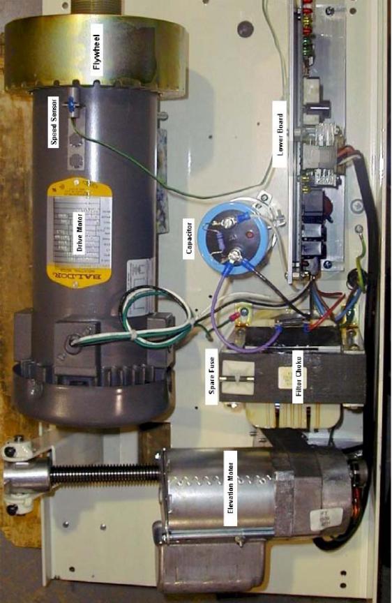
Flyw heel |
70010 |
$75.15 |
|
M otorBracket |
70043 |
$59.70 |
|
Tension Screw |
70071 |
$2.50 |
|
M etalSpacer |
70089 |
$1.89 |
3 pertread |
RubberSpacer |
70090 |
$1.65 |
2 pertread |
Hitch Pin |
233 |
$0.42 |
2 pertread |
Drive Belt |
220J10 |
$25.05 |
|
M otorBrush, 110V |
70222 |
$15.53 |
2 pertread |
M otorBrush H older |
m isc |
$58.16 |
|
M otorBrush Cap |
m isc |
$7.11 |
|
Foam Block |
70103 |
$8.35 |
|
Elevation Assem bly |
70027 |
$181.02 |
|
Elevation M otor,110V |
70088 |
$275.00 |
|
Elevation Potentiom eter |
71013 |
$32.72 |
|
Elevation Pins |
70032 |
$2.83 |
2 pertread |
Elevation Nut |
M ISC |
$25.05 |
|
Elevation Clevis |
70049 |
$17.28 |
|
Bearing Block |
70034 |
$14.00 |
|
Pan |
70048 |
$150.00 |
|
PW M 110V |
KBW T-110 |
$280.50 |
|
R ELAY Board,PW M |
70213 |
$100.50 |
|
N ylon Spacer,# 8 Screw |
71035 |
$0.25 |
|
R eading R ack Clear |
71018 |
$35.00 |
|
Display Board -8700PR G (C losed Loop) |
70196-CL |
$518.00 |
|
Display Board -8700SST (C losed Loop) |
70173-CL |
$541.08 |
|
Display Board -SPRINT4 (C losed Loop) |
70191-CL |
$275.00 |
|
D isplay Board -SPR IN T -M etric |
70191-M etric |
$285.00 |
|
Display Board -SPRIN T -7 M ph |
70191-RTM |
$285.00 |
|
SO NAR TransducerW /cable |
70179 |
$60.15 |
|
SO NAR Ranging Board |
70178 |
$100.20 |
|
SO NAR H ardware |
70177 |
$8.75 |
|
15
M em brane Panel-SPRINT3/4 |
70190 |
$167.00 |
|
M em brane Panel-8700PRG |
70195 |
$225.45 |
|
M em brane Panel-SST |
70171 |
$225.45 |
|
M em brane Panel-NM A (C RT,PRT) |
70191-NM A |
$210.42 |
|
Velcro C ircle |
70096 |
$0.85 |
|
Velcro Strip |
70095 |
$5.00 |
|
D rive RollerAssem bly |
70036 |
$215.75 |
m ustorderw/CV-18-2 |
Sheave,FrtR oller |
CV-18-2 |
$20.04 |
|
Take Up RollerAssem bly |
70039 |
$200.40 |
|
DC Transform er,9V 110V |
5302 |
$24.63 |
|
ControlPanelFram e |
70018 |
$114.90 |
|
C ontrolPanelW /SonarHole |
70018-S |
$116.90 |
|
BracketSonar |
70172 |
$5.00 |
|
Upright,Left |
70020 |
$116.57 |
|
Upright,R ight |
70019 |
$116.57 |
|
StablizerPlate |
70210 |
$25.00 |
|
C ontrolPanelEnd C ap,R ight |
70061 |
$8.52 |
|
ControlPanelEnd Cap ,Left |
70062 |
$8.52 |
|
Fram e Rail,Left |
70016 |
$215.17 |
|
Fram e Rail,R ight |
70015 |
$215.17 |
|
D ecal,Fram e,R ight |
70055 |
$22.45 |
|
Decale,Fram e,Left |
70056 |
$22.45 |
|
Side Fram eTop Cover |
70017 |
$51.35 |
|
Harness,SPRINT4 Upper |
70211 |
$30.00 |
|
Harness,SPRINT4 Lower |
70212 |
$15.05 |
|
Isolation Transform er |
70202 |
$429.50 |
|
Supression kit |
M ISC |
$17.00 |
|
AxiShock Supension FOO T |
71029 |
$60.00 |
RightorLeft |
FootC lam p (Solid foot) |
70008 |
$15.00 |
|
M otorCoverGrey |
70044 |
$158.65 |
m ustorderw /70209 (no charge) |
8700 Landice nam e plate |
70209 |
$8.25 |
|
M otorCover,Fire RetardantBlack |
70044-FR |
$242.15 |
|
M otorC over,Clear |
70044-CLEAR |
$317.30 |
|
8-32 x 3/4 PPHTT BL O X |
8-32_3/4_TTB |
$0.75 |
screw form otorcover |
Speed Sensor |
71007 |
$58.50 |
|
Speed SensorBracket |
70067 |
$3.76 |
|
Line Cord,with 5-15P Plug |
5211 |
$48.26 |
|
Plug, 5-15P,HospitalGrade (110V) |
5-15PHG P |
$33.00 |
|
Strain R elief |
1250 |
$0.58 |
|
Fuse, 110V |
M D A-20 |
$2.51 |
|
Fuse H older |
M DA-HO LDER |
$3.25 |
|
16
W ireless Pulse Option "Pulse Kit" |
71017 |
$167.00 |
|
ExtenderKit |
M ISC |
$25.05 |
|
ReceiverKit |
70074/M ISC |
$125.25 |
|
Pulse Belt/Transm itter |
70072/70073 |
$108.55 |
|
Pulse Receiver |
70074 |
$100.20 |
|
ExtenderC able |
71009 |
$16.70 |
|
RightAngle Adapter |
71010 |
$8.35 |
|
Isolation Leakage O ption |
M ISC |
$167.00 |
|
Isolation Leakage O ption DealerInstaled |
M ISC |
$20.00 |
|
Traction Strip |
70005 |
$11.41 |
|
Cover,Side Fram e |
70017 |
$51.35 |
|
SIDE FR AM E XL |
|
$190.00 |
|
Side R ail |
70052 |
$53.44 |
|
RailClam p |
70021 |
$33.57 |
|
Cross Bar |
70051 |
$25.05 |
m ustorderw /1858 |
Cross Bar Foam |
1858 |
$7.55 |
|
Hardware Kit |
71020 |
$25.05 |
|
M edicalR ail |
70135 |
$104.38 |
m ustorderw /70185 |
Foam M edical& Runners R ail |
70185 |
$8.35 |
|
Installation Charge,O ptionalRails |
M ISC |
$108.55 |
|
Spacer,RailSupport |
70006 |
$5.01 |
|
End Cap |
70045 |
$12.53 |
|
W heel |
4851 |
$6.68 |
2 pertread |
N M A Sticker |
70188 |
$1.67 |
|
Safety Lanyard |
71011 |
$15.50 |
|
8700SPRIN T User' M anual |
72008 |
$8.35 |
|
8700PRG User' M anual |
72012 |
$8.35 |
|
8700SST User' M anual |
72011 |
$8.35 |
|
Institutional Brochures |
70199 |
|
|
Hom e Brochures |
70200 |
|
|
Q uality C onstruction M anual |
72017 |
|
|
Touch U p Paint |
70224 |
$25.05 |
|
Slipcote Lubricant1oz Packet |
71037 |
$1.50 |
|
Slipcote LubricantQ UAR T |
71030 |
$35.00 |
4 cans/save$4.00 |
Slipcote Lubricant G ALLON |
71031 |
$96.00 |
16cans/save$39.00 |
Applicator |
71016 |
$4.00 |
|
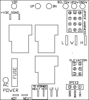
17
8700 COMERCIAL MOTOR PAN COMPONENTS
18
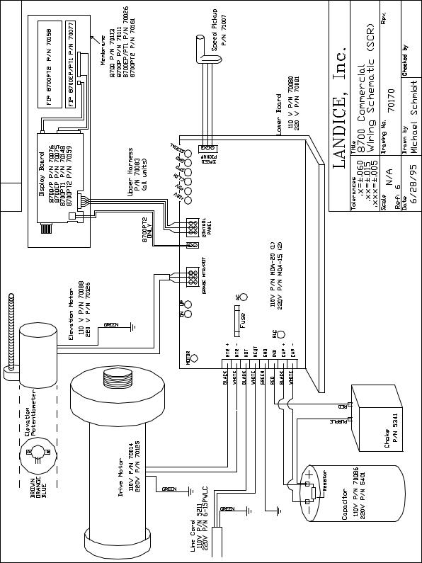
8700 COMMERCIAL LOWER WIRING SCHEMATIC
19
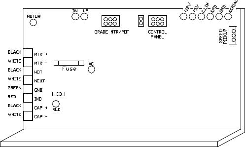
LED (light emitting diode) configurations: SCR lower board
The SCR lower board is designed with diagnostic LED lights. The LED’s are color coded according to their specific function. Green indicates a properly operating treadmill; the green lights should always be ON when power is supplied to the treadmill. Yellow indicates a treadmill function. Red indicates a treadmill malfunction. Here is a list of each LED and what it signifies:
MOTOR (yellow) – The MOTOR LED illuminates when dc (direct current) voltage is sent to the drive motor. The LED gets brighter when the dc output is increased.
RLC (yellow) – The RLC (R = Reactance / L = Inductance / C = Capacitance) LED illuminates when the filtering system is properly working. The filtering system includes the capacitor and filter choke. If there is a short in either component then the RLC light will not come on.
DN & UP (yellow) – The DN and UP LED lights tell us if the elevation DN and UP relays are functioning properly. When the LED lights, it tells us that the relay has energized and is sending high voltage (110vac or 220vac) to the elevation motor.
AC PWR (green) – The AC PWR (Alternating Current Power) illuminates when AC line voltage is delivered to the treadmill. It then passes through the in-line fuse (110)/s(220) and lights the AC PWR LED.
+12V (green) – When the proper AC voltage is delivered to the treadmill, passes through the in-line fuse/s, through the full wave bridge rectifier (changes AC to DC), through the transformer (steps down
DC to +12vdc) then the +12V LED lights.
20
C. LIM (red) – The C.LIM or Current Limit LED should NEVER come on. This diagnostic light is used to determine the condition of the treadbelt and deck. The SCR board has a built-in amp meter. When the treadbelt belt and deck system wears, the amperage will increase. When this amperage reaches its max limit, the lower board will shut down its power (treadbelt will slow down / low torque) to the drive motor and the C.LIM LED will illuminate.
SPD (yellow) – The SPD LED flashes on and off (relative to speed) when the speed sensor is operating properly.
GRD (red) – The GRD LED should NEVER come on. It illuminates only when the elevation potentiometer becomes out of calibration.
SERIAL (red) – The SERIAL LED should NEVER come on. It illuminates only when there is a serial error. This could be a loose or pushed pin on the main wire harness.
+5V (green) – The +5V light comes on when there is power going to the Upper Display. If the light is not on check wire harness for connections. If it ‘s not the wire harness then the MCB is defective.

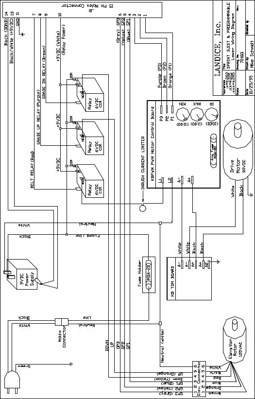
21
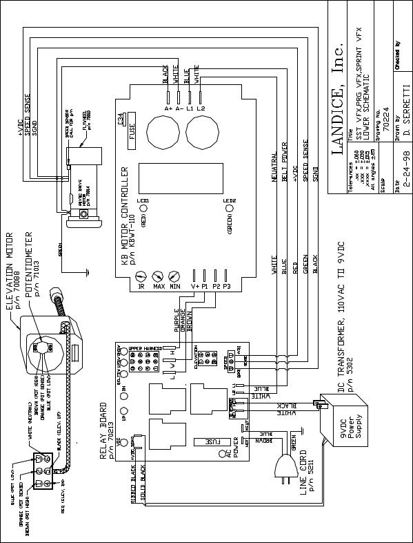
8700 HOME SST VFX, PRG VFX, SPRINT VFX CLOSED LOOP (SPEED SENSOR)
22
8700 SST, PRG and SPRINT VFX TREADMILL
All VFX treadmills utilize CLOSED LOOP speed control.
All treadmills listed as VFX in the warranty database use a speed sensor.
23
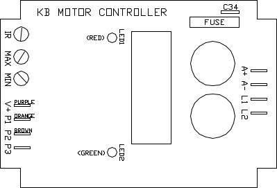
LED LIGHTS ON PWM
The PWM lower board is designed with two diagnostic LED lights. The LED’s are color coded according to their specific function.
LED 1 (red) – This indicates a high current draw similar to the C.LIM LED on our SCR lower control board. LED 1 will only light if there is high current being used due to a possible worn out treadbelt and deck system or it can also light if the IR pot is out of adjustment. The IR pot controls how the PWM board reacts to varying loads (users’ weights). If the IR pot is out of adjustment you will notice the treadbelt will surge and the red LED 1 will flash in unison with the belt surge.
LED 2 (green) – This indicates proper line voltage is being supplied to the PWM board. This line voltage is delivered to the PWM via the belt relay located on the relay board. When the belt relay energizes 110VAC or 220VAC is sent to the input terminals (L1 & L2) on the PWM board and LED 1 illuminates.
24
LED (light emitting diode) configurations: RELAY BOARD
The RELAY board is designed with diagnostic LED lights. The LED’s are color coded according to their specific function. Green indicates a properly operating treadmill; the green lights should always be ON when power is supplied to the treadmill. Yellow indicates a treadmill function. Red indicates a treadmill malfunction. Here is a list of each LED and what it signifies:
AC PWR (green) - The AC PWR (Alternating Current Power) illuminates when AC line voltage is delivered to the treadmill. It then passes through the in-line fuse (110)/s(220) and lights the AC PWR LED.
VDC (green) – The VDC LED will light when it receives DC voltage from the DC power supply.
DN & UP (yellow) – The DN and UP LED lights tell us if the elevation DN and UP relays are functioning properly. When the LED lights, it tells us that the relay has energized and is sending high voltage (110vac or 220vac) to the elevation motor.
UPSW (green) – This LED will illuminate when the low voltage dc is delivered from the upper display board to the elevation UP relay. This low voltage dc is what energizes the coil of the relay.
DNSW (green) - This LED will illuminate when the low voltage dc is delivered from the upper display board to the elevation DOWN relay. This low voltage dc is what energizes the coil of the relay.
BELTSW (green) - This LED will illuminate when the low voltage dc is delivered from the upper display board to the belt (motor start) relay. This low voltage dc is what energizes the coil of the relay.
SPD (yellow) – The SPD LED flashes on and off (relative to speed) when the speed sensor is operating properly.
PWM (yellow) – This LED will light when the upper board is sending a speed signal to the PWM.
Both the PWM LED and BELTSW LED must be lit for belt movement.
25
8700 SST, PRG and SPRINT 3, NON VFX TREADMILL
All NON VFX treadmills utilize OPEN LOOP speed control and no relay boards.
Sprint 3 treadmills have push button controls
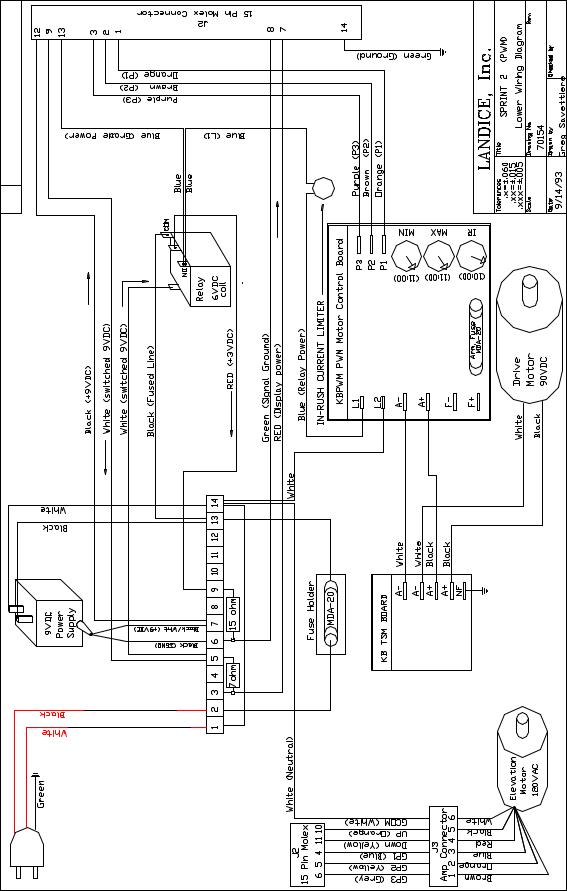
26
8700 SPRINT 2
Safety lanyard, speed control dial (not push button), KBWT-110 SCR motor control
Loading...