

Page 1
MOUNTING AND CONNECTING THE DEVICE
TECHNICAL DETAILS
LANCOM LN-830U
4
Quick Reference Guide
Cloud-ready
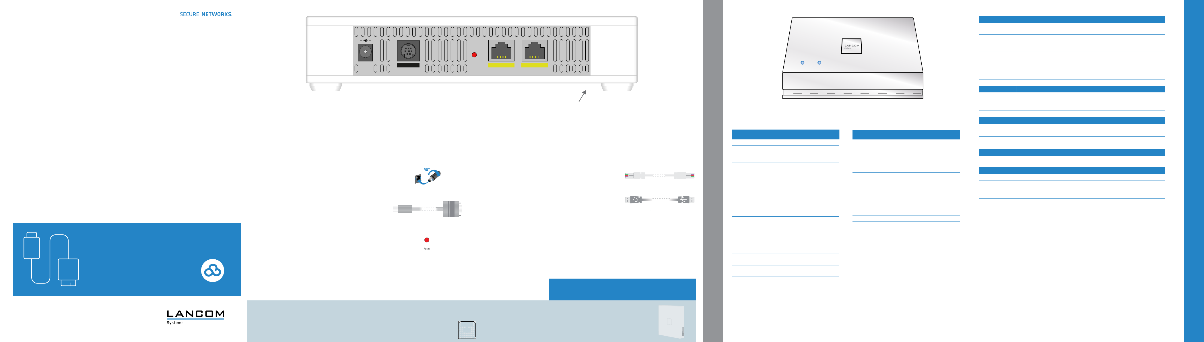
Power
a
After connecting the cable to the device, turn the connector 90°
clockwise to prevent it from accidental un plugging. Use only the
supplied power adapter.
Conguration interface
b
Use a serial conguration cable to connect the serial interface
(COM) to the serial interface of the device you want to use for
conguring / monitoring (separately available).
Reset button
c
Pressed up to 5 seconds: device restart
Pressed until rst ashing up of all LEDs:
conguration reset and device restart
Please observe the following when setting up the device
A For devices to be operated on the desktop, please attach the adhesive rubber
footpads
A Do not rest any objects on top of the device and do not stack multiple devices
A In case of wall or ceiling mounting, use the drilling template as supplied
DC 12 V
a
Config (Com) ETH2 ETH1 (PoE)Reset
b c d e
Ethernet interfaces
d
Use the Ethernet cable to connect the interfaces ETH1 (PoE) or
ETH2 to your PC or a LAN switch.
USB interface (inner right side)
e
Connect compatible USB devices either directly to the USB
interface, or use a suitable USB cable.
A Keep the ventilation slots on the side of the device clear of obstruction
A Lockable wall and ceiling mounting with the LANCOM Wall Mount (LN)
(available as an accessory)
Please note that when the two Wi-Fi modules are operating in the
same frequency band, mutual interference cannot be ruled out.
5
a b
a Power
Off Device switched off
Green, permanently* Device operational, resp. device paired /
Red / green, blinking Conguration password not set. Without a
Orange / green,
blinking alternately with
the WLAN link LED
Orange / red, blinking
alternately with the
WLAN link LED
1x green inverse
blinking*
2x green inverse
blinking*
3x green inverse
blinking*
*) The additional power LED statuses are displayed in 5-seconds
rotation if the device is congured to be managed by the LANCOM
Management Cloud.
claimed and LANCOM Management Cloud
(LMC) accessible
conguration password, the conguration
data in the device is unprotected.
At least one Wi-Fi module is in managed
mode and has not found a WLAN controller yet. The corresponding Wi-Fi module(s)
is/are switched off until a WLAN controller
is found to supply a conguration, or until
being switched manually into another
operating mode.
At least one Wi-Fi module is in managed
mode and has found a WLAN controller.
However, the WLAN controller cannot
assign a conguration because the
rmware and/or the device's loader
version is not compatible with the WLAN
controller.
Connection to the LMC active, pairing OK,
device not claimed
Pairing error, resp. LMC activation code
not available
LMC not accessible, resp. communication
error
b WLAN Link
Off No Wi-Fi network dened or Wi-Fi module
deactivated. The Wi-Fi module is not
transmitting beacons.
Green, permanently At least one Wi-Fi network is dened and
Wi-Fi module activated. The Wi-Fi module
is transmitting beacons.
Green, inverse ashing Number of ashes = number of connected
Wi-Fi stations and P2P wireless connections, followed by a pause (default).
Alternatively the frequency of the ashing
can indicate signal strength over the
dened P2P link or the signal strength
between the access point and the device
operating in client mode.
Green, blinking DFS scanning or other scan procedure.
Red, blinking Wi-Fi module hardware error
Hardware
Power supply 12 V DC, external power adapter (110 or 230 V) with bayonet connector to secure against
Power consumption Approx. 11 W via 12 V / 2 A power adapter (value refers to the power of the access point
Environment Temperature range 0 °C to 40 °C for wall mounting (vertical mounting position) and
Housing Robust synthetic housing, rear connectors, ready for wall and ceiling mounting; measures
Number of fans None; fanless design, no rotating parts, high MTBF
WLAN
Frequency band 2400-2483.5 MHz (ISM) or 5150-5725 MHz (restrictions vary between countries)
Radio channels 2.4
GHz
Radio channels 5 GHz Up to 19utomatic dynamic channel selection required)
Interfaces
ETH1 (PoE) 10 / 100 / 1000 Base-TX, autosensing, auto node hub, PoE compliant with IEEE 802.3af
ETH2 10 / 100 / 1000 Base-TX, autosensing, auto node hub
USB USB 2.0 hi-speed host port
Serial interface Serial conguration interface/COM-port (8-pin mini-DIN): 9,600 - 115,000 baud
Declaration of conformity
Hereby, LANCOM Systems declares that this radio equipment is in compliance with Directive 2014/53/EU. The full text
of the EU declaration of conformity is available at the following internet address: www.lancom-systems.com/ce/
Package content
Documentation Quick Reference Guide (DE/EN); Installation Guide (DE/EN)
Cable 1 Ethernet cable, 3 m
Power adapter External power adapter, NEST 12 V / 2 A DC/S, barrel connector 2.1 / 5.5 mm bayonet,
disconnection or PoE as per 802.3af via ETH1
without power adapter), about 12 W via PoE, in each case max. +3 W when operating the
USB port.
0 °C to 35 °C for ceiling mounting (horizontal mounting position); humidity 0-95 %;
non-condensing
205 x 42 x 205 mm (W x H x D)
Up to 13 channels, max. 3 non-overlapping (2.4-GHz band)
LANCOM item no. 111760 (not for WW devices)
LANCOM, LANCOM Systems and LCOS are registered trademarks. All other names or descriptions used may be trademarks or registered
trademarks of their owners. Subject to change without notice. No liability for technical errors and/or omissions. 111815/0718
 Loading...