

Page 1
TOUCHPOINT SERIES 4800T
Operation Manual
PN: 28-0931
4800T
Lancer Corp.
6655 Lancer Blvd.
San Antonio, Texas 78219
800-729-1500
Technical Support/Warranty: 800-729-1550
custserv@lancercorp.com
lancercorp.com
Manual PN: 28-0931
NOVEMBER 2013
FOR QUALIFIED INSTALLER ONLY
“Lancer” is the registered trademark of Lancer © 2014 by Lancer, all rights reserved.
Page 2

ABOUT THIS MANUAL
This booklet is an integral and essential part of the product and should be handed over to the operator after the
installation and preserved for any further consultation that may be necessary. Please read carefully the guidelines and
warnings contained herein as they are intended to provide the user with essential information for the continued safe
use and maintenance of the product. In addition, it provides GUIDANCE ONLY to the user on the correct services and
site location of the unit.
The installation and relocation, if necessary, of this product must be carried out by qualied personnel with up-to-date
safety and hygiene knowledge and practical experience, in accordance with current regulations.
TABLE OF CONTENTS
SPECIFICATIONS................................................................................................................................4
PRE-INTALLATION CHECKLIST........................................................................................................5
WARNINGS/CAUTIONS...................................................................................................................6-9
1. INSTALLATION............................................................................................................................10
1.1 RECIEVING THE UNIT.......................................................................................................10
1.2 UNPACKING........................................................................................................................10
1.3 DRAIN SPIDER...................................................................................................................10
1.4 SELECTING THE LOCATION.............................................................................................11
1.5 LEVELING THE DISPENSER.............................................................................................11
1.6 INSTALLING AN ICEMAKER.........................................................................................11-12
1.7 ADA STANDARDS FOR ACCESSIBLE DESIGN................................................................12
1.8 CONNECTING TO ELECTRICAL POWER....................................................................12-13
1.9 CONNECTING TO WATER SUPPLY LINES.......................................................................13
1.10 CONNECTING TO CO2.....................................................................................................13
1.11 INSTALLATION OF THE UNIT AND PUMP DECK.......................................................13-14
1.12 CHECKING FOR LEAKS.....................................................................................................14
1.13 PRE-INSTALL.................................................................................................................14-15
1.14 CARBONATOR AND SYRUP PURGING............................................................................16
1.15 SETTING UP BRANDS..................................................................................................16-19
1.16 FILLING ICE AND SETTING RATIO...................................................................................19
1.17 OTHER................................................................................................................................20
2. CLEANING AND SANITIZING INSTRUCTIONS.........................................................................20
2.1 CLEANING AND SANITIZING SOLUTIONS..................................................................20-21
2.2 DAILY CLEANING...............................................................................................................21
2.3 ICE BIN CLEANING............................................................................................................21
2.4 CLEANING AND SANITIZING BEVERAGE COMPONENTS - FIGAL SYSTEMS........21-22
2.5 CLEANING AND SANITIZING BEVERAGE COMPONENTS - BAG-IN-BOX
SYSTEMS...........................................................................................................................23
2.6 TO ACCESS SERVICE AREA............................................................................................23
2.7 ICE CHUTE CLEANING......................................................................................................24
2.8 REMOVAL OF ICE CHUTE FOR SERVICE........................................................................24
3. SOFTWARE, MULTIMEDIA & TOUCH SCREEN TROUBLESHOOTING............................25-27
4. MECHANICAL TROUBLESHOOTING...................................................................................28-32
5. AUTOMATIC AGITATION AND LOW ICE ALARM CONTROL..................................................32
6. DISPENSER DISPOSAL.............................................................................................................33
2
Page 3

7. UNIT DIMENSIONS................................................................................................................34-35
8. ILLUSTRATIONS AND PARTS LISTINGS..................................................................................36
8.1 SPARE PARTS LIST 1........................................................................................................36
8.2 SPARE PARTS LIST 2........................................................................................................37
8.3 SPARE PARTS LIST 3: CONTROL BOX ASSY..................................................................38
8.4 SPARE PARTS LIST 4: SPLASH PLATE............................................................................39
8.5 PLUMBING DIAGRAM........................................................................................................40
8.6 ELECTRONICS DIAGRAM.................................................................................................41
3
Page 4
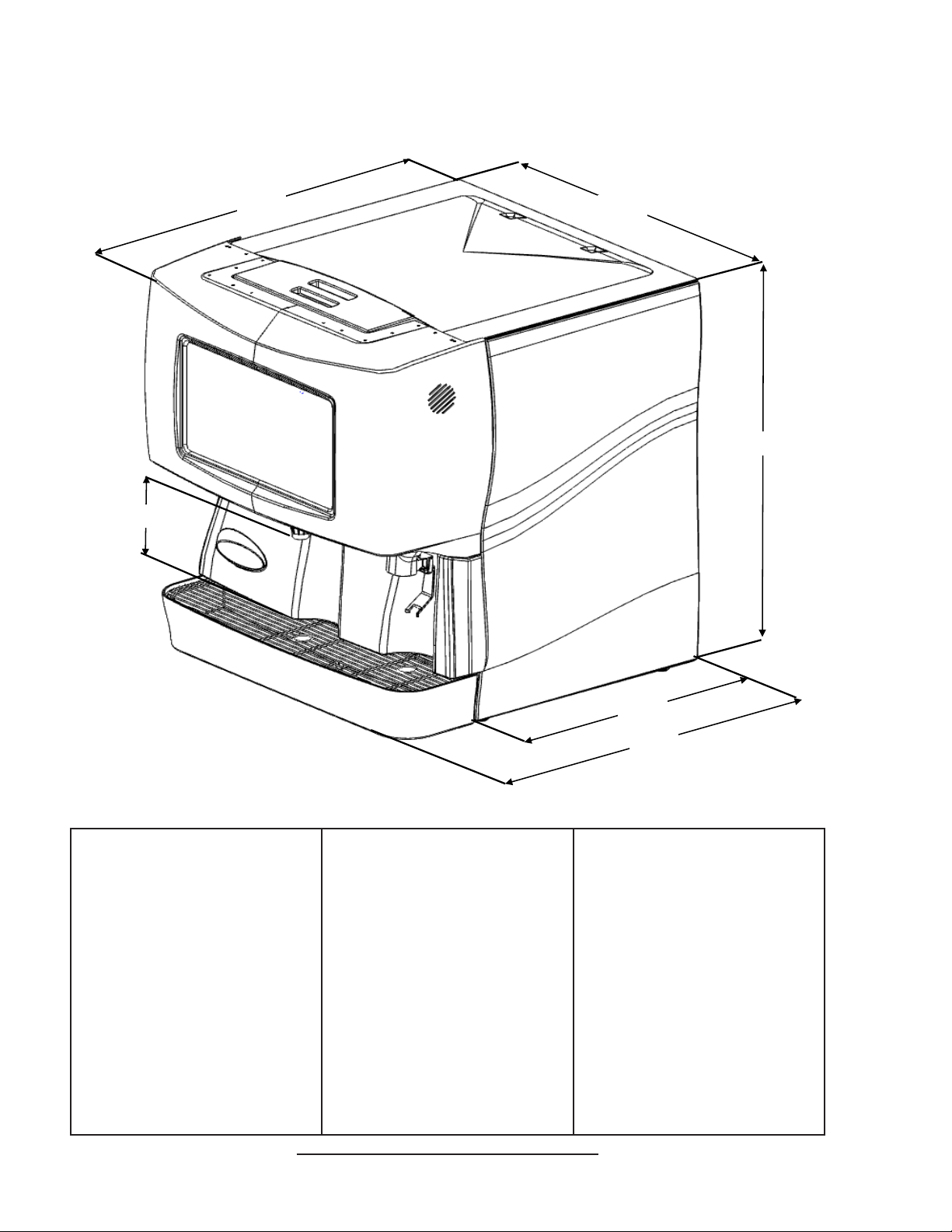
TOUCHPOINT SPECIFICATIONS
9.4"
33.4"
32.6"
37.3"
DIMENSIONS
Width: 32.5 in (825 mm)
Depth: 33.7 in (856 mm)
Height: 37.3 in (947 mm)
SPACE REQUIRED
Width: 41.3 in (1049 mm)
Depth: 38.5 in (978 mm)
Height: Determined by manual
lling requirements or ice maker
mounting
ELECTRICAL
115VAC/60Hz/2AMPs
220-240VAC/50/60Hz/1AMPs
WEIGHT
With ice: 648 lbs (293 kg)
Shipping: 498 lbs (225 kg)
PLAIN WATER SUPPLY
Min owing pressure: 75 PSIG
(5.28 kg/cm2, 0.516 MPA)
CARBONATOR WATER SUPPLY
ICE
Capacity: 250 lbs (113 kg)
Dispensable: 180 lbs (81 kg)
Min owing pressure: 25 PSIG
(1.76 kg/cm2, 0.172 MPA)
Max static pressure: 50 PSIG
(3.52 kg/cm2, 0.345 MPA)
FITTINGS
Water for carbonator inlet:
3/8” barb
Plain water inlet: 3/8” barb
Brand syrup inlets: 3/8” barb
Injection avor inlets: 1/4” barb
CARBON DIOXIDE (CO2)
Min pressure: 70 PSIG
(4.92 kg/cm2, 0.483 MPA)
Max pressure: 80 PSIG
(5.62 kg/cm2, 0.552 MPA)
CO2 inlet: 3/8” barb
This unit emits a sound pressure level below 70 dB
23.0"
31.8"
4
Page 5
PRE-INSTALLATION CHECKLIST
BEFORE GETTING STARTED
Each unit is tested under operating conditions and is thoroughly inspected before shipment.
At the time of shipment, the carrier accepts responsibility for the unit. Upon receiving the
unit, carefully inspect the carton for visible damage. If damage exists, have the carrier note
the damage on the freight bill and le a claim with carrier. Responsibility for damage to the
dispenser lies with the carrier.
TOOLS REQUIRED
Oetiker Pliers Slotted Screwdriver
Tubing Cutters Phillips Screwdriver
Wrench Cordless Drill
POST MIX ACCESSORIES
CO2 Regulator Set CO2 Supply
Beverage Tubing Oetiker Clamps/Fittings
Water Booster Water Regulator
Precision Cutters (if removing/replacing carbonator tank)
BIB SYSTEM
BIB Rack BIB Regulator Set
BIB Syrup Boxes
BIB Connectors - ensure you have the correct connectors for syrup lineup.
CONSIDER LOCATION OF THE FOLLOWING PRIOR TO INSTALL
Water supply lines Drain
Is the countertop level? Heating and air conditioning ducts
Grounded electrical outlet.
Enough space to install the dispenser. Include space for a top-mounted ice machine, if necessary.
Does the top-mounted ice machine have a minimum clearance on all sides?
Located away from direct sunlight or overhead lighting.
Can the countertop support the weight of the dispenser? Be sure to include the weight of an ice
machine (if necessary) plus the weight of the ice.
This unit is not suitable for use in an area where a water jet could be used.
5
Page 6

! !
WARNING/ADVERTENCIA/AVERTISSEMENT
! The dispenser is for indoor use only. This unit is not a toy. Children should not be supervised not to play with
appliance. It should not be used by children or inrm persons without supervision. This appliance is not intended
for use by persons (including children) with reduced physical, sensory or mental capabilities, or lack of experience
and knowledge, unless they have been given supervision or instruction concerning use of the appliance by a person
responsible for their safety. Cleaning and user maintenance shall not be performed by children without supervision.
This appliance can be used by children aged from 8 years and above and persons with reduced physical, sensory or
mental capabilities or lack of experience and knowledge if they have been given supervision or instruction concerning
use of the appliance in a safe way and understand the hazards involved. This unit is not designed to dispense dairy
products. The min/max ambient operating temperature for the dispenser is 40°F to 105°F (4°C to 41°C). Do not
operate unit below minimum ambient operation conditions. Should freezing occur, cease operation of the unit and
contact authorized service technician. Service, cleaning and sanitizing should be accomplished only by trained
personnel. Applicable safety precautions must be observed. Instruction w!arnings on the product being used must be
followed.
! El dispensador sólo debe usarse en interiores. Esta unidad no es un juguete. Los niños deben ser supervisados
para no jugar con aparato. No la deben usar niños ni personas discapacitadas sin supervisión. Esta unidad no está
destinada al uso por parte de personas (incluso niños) con capacidad física, sensorial o mental reducida, o sin
experiencia y conocimientos sucientes, a menos que una persona responsable de su seguridad les haya dado
supervisión o capacitación en el uso de la unidad. Limpieza y mantenimiento de usuario no deberá ser realizada por
los niños sin supervisión. Este aparato puede ser utilizado por niños de 8 años o más y las personas con
capacidades físicas, sensoriales o mentales, o por falta de experiencia y conocimientos que hayan recibido
supervisión o instrucciones relativas al uso del aparato de una manera segura y comprenda los peligros
involucrados. Esta unidad no ha sido diseñada para suministrar productos lácteos. La temperatura ambiente
operativa mínima / máxima para el dispensador es de 40°F a 105°F (4°C a 41°C). No opere la unidad debajo de las
condiciones de funcionamiento ambientales mínimos. En caso de congelación se produce, cesar la operación de la
unidad y el contacto técnico de servicio autorizado. Servicio de limpieza y desinfección deben llevarse a cabo
solamente por personal capacitado. Es necesario tomar medidas de seguridad aplicables. Advertencias de las
instrucciones sobre el producto utilizado se deben seguir.
! Le distributeur est destiné à un usage à l’intérieur seulement. Cet appareil n’est pas un jouet. Les enfants doivent
être surveillés an de ne pas jouer avec l’appareil. Il ne devrait pas être utilisé par des enfants ou des personnes
inrmes sans surveillance. Cet appareil n’est pas destiné à un usage par des personnes (y compris les enfants)
ayant des capacités physiques, sensorielles ou mentales réduites, ou manquant d’expérience et de connaissances,
à moins qu’elles obtiennent de la surveillance ou des instructions au sujet de l’utilisation de l’appareil de la part
d’une personne chargée de leur sécurité. Nettoyage et entretien de l’utilisateur ne doivent pas être effectués par
des enfants sans surveillance. Cet appareil peut être utilisé par des enfants âgés de 8 ans et plus et les personnes
ayant des capacités ou le manque d’expérience et de connaissances physiques, sensorielles ou mentales réduites si
elles sont sans surveillance ou instruction concernant l’utilisation de l’appareil en toute sécurité et de comprendre les
risques impliqués. Cet appareil n’est pas conçu pour distribuer des produits laitiers. La température de service
ambiante minimum/maximum pour le distributeur est de 40°F à 105°F (4°C à 41°C). Ne pas utiliser l’appareil dans
des conditions de performance environnementale minimale. En cas de gel, cesser l’exploitation de l’unité et contactez
un technicien agréé. Nettoyage et désinfection doivent être effectuées uniquement par du personnel qualié. Vous
devez prendre des mesures de sécurité. Avertissements instructions sur le produit utilisé doivent être respectées.
6
Page 7
!
This unit has been factory sanitized per Lancer specications.
Listed below are six critical elements which will aid in a successful installation.
1. Fill water bath until water overows from tank overow tube.
2. The carbonator pump motor must be disconnected from the power supply (see Section 1.7) prior to connection to
water .. supply for initial build up of ice bank. Failure to do so will result in automatic shut off of carbonator (see item 6
below) or damage to the pump.
3. If this dispenser is installed in an area that is susceptible to ±10% variation of the nominal line voltage, consider
installing a surge protector or similar protection device.
4. There is a ve (5) minute delay which prevents the compressor and condenser fan from starting until the delay
has lapsed. If electrical current is interrupted, there is always a ve (5) minute delay before the compressor starts.
5. Supply Water Pressure: Minimum - 25 PSI (0.172 MPA); Maximum - 50 PSI (0.345 MPA); If pressure is over 50
PSIG (0.345 MPA), a water pressure regulator must be used.
6. On units with the built in water regulator, the regulator must be removed if inlet water pressure is less than 25
PSIG. (0.172 MPA)
DISPENSER INSTALLATION HIGHLIGHTS
!
!
Esta unidad ha sido saneada en fabrica por las especicaciones de Lancer.
A continuacion se relacionan 6 puntos importantes para una connecta instalacion.
1. Llene el bano-Maria hasta que el agua se desborde sobre el tubo que controla la derrama del tanque.
2. El motor de la bomba del carbonatador debe desconectarse electricamente (Ver Manual - Seccion 1.7) antes
de conectar el suministro de agua para la formacion inicial del banco de hielo. De no hacerse esto resultaria en un
bloqueo automatico del carbonatador (ver abajo el punto 6) o en danos a la bomba.
3. Si la unidad va a ser instalada en un area en la que puedan darse variaciones de voltage de + 6 - 10% de su
valor nominal, se debe considerar la conveniencia de instalar un estabilizador de corriente o sistema de proteccion
similar.
4. Hay una demora de 5 minutos que evita que el compresor y el abanico del condensador arranquen hasta pasado
ese tiempo. Si hay algun corte en la corriente electrica siempre se producira esa demora de 5 minutos antes de
arrancar el compresor.
5. Presión de suministro del agua de red: Minimo 25 PSI (0.172 MPA); Maximo 50 PSI (0.345 MPA). En unidades
sin regulador de presión incorporado, si la presión del agua es superior a 50 PSIG (0.345 MPA) se debe usar un
regulador de presión.
6. En unidades con regulador de presión incorporado, el regulador debe der eliminado cuando la presión de entrada
de agua sea inferior a 25 PSIG (0.172 MPA).
REGLES DE SECURITE POUR L’NSTALLATION DU DISTRIBUTEUR DE SODAS
!
La proprètè da cet ensamable est assurè à I’usine sulvant les spècications èmis par Lancer .
Il est essentiel de respecter les 6 points suivants pour l’installation de l’appareil:
1. Remplir le bain-Maire jusqu’a ce que l’eau dèborde par le tuyau de trop-plein du rèservoir.
2. Le moteur de la pompe du carbonateur doit etre dèbranchè de l’alimentation èlectrique (Voir le manuel, Section 1.7) avant l’arrivèe de l’eau pour la formation initiale de la glace. Oublier ou nègliger cette opèration provoquera
l’arret automatique du carbonateur (voir le point 6 cidessous) ou causera des dommages à la pompe.
3. Si le distributeur es installè dans une zone ou la tension èlectrique nominale est susceptible de variations de (+)
10%, il est conseillè d’installer un appaeil de protection contre les sautes de courant.
4. Un d’lai de 5 minutes empeche le compresseur et la ventilation du condesateur de se mettre en marche avant
que ce lees de temps ne se soit ècoulè. Lorsque le courant èlectrique es interrompu, il y a toujours un dèlai de 5
minutes avant que le presseur ne se mette en.
5. Pression de l’eau: Minimum 25 PSI (0.172 MPA); Maximo 50 PSI (0.345 MPA). Sur les unitès qui n’ont pas de
règulateur de pression d’eau incorprè, si la pression d’H2O est supèrieure à 50 PSIG (0.345 MPA), un règulateur de
pression d’eau doit etre utilsisè.
6. Sur les unitès avec règulateur d’eau incorporè, le règulateur doit etre enlevè si la pression d’arrivve est inferièure
à 25 PSIG (0.172 MPA)
PUNTOS IMPORTANTES EN LA UNIDAD DISPENSADORA
!
!
7
Page 8
ELECTRICAL WARNING/ADVERTENCIA ELÉCTRICA/
F F
AVERTISSEMENT ÉLECTRIQUE
F Check the dispenser serial number plate for correct electrical requirements of unit. Do not plug into a wall
electrical outlet unless the current shown on the serial number plate agrees with local current available. Follow
all local electrical codes when making connections. Each dispenser must have a separate electrical circuit. Do not
use extension cords with this unit. Do not ‘gang’ together with other electrical devices on the same outlet. The
keyswitch does not disable the line voltage to the transformer primary. Always disconnect electrical power to the unit
to prevent personal injury before attempting any internal maintenance. The resettable breaker switch should not
be used as a substitute for unplugging the dispenser from the power source to service the unit. Only qualied
personnel should service internal components of electrical control housing. Make sure that all water lines are tight
and units are dry before making any electrical connections!
F Verique la placa con el número de serie del dispensador, donde encontrará los requisitos eléctricos correctos
de la unidad. No enchufe la unidad en un tomacorriente de pared a menos que la corriente indicada en la placa con
el número de serie concuerde con la corriente local disponible. Al hacer las conexiones, respete todos los códigos
eléctricos locales. Cada dispensador debe tener un circuito eléctrico independiente. No use extensiones con esta
unidad. No la conecte junto con otros dispositivos eléctricos al mismo tomacorriente. El interruptor de llave no corta
el voltaje de línea al transformador primario desconecte siempre la alimentación eléctrica a la unidad para evitar
lesiones personales antes de tratar de realizar tareas de mantenimiento. El disyuntor de sobrecarga reseteable no
se debe usar como sustituto para desenchufar el dispensador de la fuente de alimentación para realizar tareas de
servicio de la unidad. El servicio de los componentes internos de la caja de control eléctrico debe conarse
exclusivamente a personal calicado. Asegúrese de que todas las líneas de agua estén ajustadas y las unidades
estén secas antes de hacer conexiones eléctricas.
F Examinez la plaque de numéro de série du distributeur pour connaître les bonnes exigences en matière
d’électricité pour l’appareil. Ne le branchez pas à une prise électrique murale à moins que le courant indiqué sur la
plaque de numéro de série corresponde au courant local disponible. Respectez tous les codes électriques locaux
lorsque vous faites des connexions. Chaque distributrice doit avoir un circuit électrique séparé. N’utilisez pas de
cordons prolongateurs avec cet appareil. Ne pas le brancher avec d’autres appareils électriques sur la même prise.
L’interrupteur à clé ne coupe pas la tension secteur au transformateur primaire. Débranchez toujours le courant
électrique à l’appareil, an de prévenir des blessures, avant de faire un entretien interne quelconque. Le disjoncteur
réarmable ne devrait pas être utilisé au lieu de débrancher le distributeur de la source d’alimentation en électricité
pour faire de l’entretien/une réparation de l’appareil. Seul le personnel qualié devrait faire l’entretien/la réparation
des composants internes dans le logement des commandes électriques. Assurez-vous que toutes les conduites
d’eau sont étanches et que les appareils sont secs avant de faire des connexions électriques!
CO2/CARBON DIOXIDE /El ANHÍDRIDO CARBÓNICO/
5 5
DIOXYDE DE CARBONE
5 Carbon Dioxide (CO2) is a colorless, noncombustible gas with a light pungent odor. High percentages of CO2 may
displace oxygen in the blood. Prolonged exposure to CO2 can be harmful. Personnel exposed to high concentrations
of CO2 gas will experience tremors which are followed by a loss of consciousness and suffocation. If a CO2 gas leak
is suspected, immediately ventilate the contaminated area before attempting to repair the leak. Strict attention must
be observed in the prevention of CO2 gas leaks in the entire CO2 and soft drink system.
5 El anhídrido carbónico (CO2) es un gas incoloro, no combustible, con un olor pungente ligero. Altos porcentajes
de CO2 en la sangre pueden desplazar el oxígeno en la sangre. La exposición prolongada al CO2 puede ser nociva.
El personal expuesto a concentraciones altas de CO2 sufre temblores seguidos de la pérdida de la consciencia y
sofocación. Si se sospecha que existe una pérdida de CO2, ventile el área contaminada antes de tratar de reparar
la pérdida. Hay que prestar suma atención para evitar pérdidas de CO2 en todo el sistema de CO2 y de bebidas
gaseosas.
5 Le dioxyde de carbone (CO2) est plus lourd que l’air et déplace l'oxygène. Le CO2 est un gaz incolore et
incombustible, ayant une odeur un peu âcre. Des concentrations fortes de CO2 peuvent déplacer l'oxygène dans le
sang. Une exposition prolongée au CO2 peut être nocive. Le personnel exposé à de fortes concentrations de CO2
gazeux éprouvera des tremblements, suivis rapidement d'une perte de conscience et de suffocation. On doit faire très
attention de prévenir les fuites de CO2 gazeux dans le système entier de CO2 et de boisson gazeuse. Si on suspecte
qu'il y a une fuite de CO2 gazeux, aérez le secteur contaminé immédiatement avant d'essayer de réparer la fuite.
8
Page 9
AUTOMATIC AGITATION/AGITACIÓN AUTOMÁTICA/
! Units are equipped with an automatic agitation system and will activate unexpectedly. Do not place hands or
foreign objects in the water bath tank. Unplug the dispenser during servicing, cleaning, and sanitizing. To avoid
personal injury, do not attempt to lift the dispenser without assistance. For heavier dispensers, use a mechanical lift.
! Las unidades están equipadas con un sistema automático de agitación, por lo que se pueden activar
repentinamente. No ponga las manos ni objetos extraños en el compartimiento donde se guarda el hielo. Durante el
servicio, la limpieza y la esterilización, desenchufe el dispensador. Para evitar lesiones personales, no trate de
levantar el dispensador sin ayuda. Para los dispensadores más pesados, use un elevador mecánico.
! Les appareils sont équipés d’un système d’agitation automatique qui s’activera de manière inattendue. Ne mettez
pas les mains ou des corps étrangers dans le compartiment d’entreposage de glace. Débranchez le distributeur
pendant l’entretien/la réparation, le nettoyage et l’aseptisation. Pour éviter des blessures, n’essayez pas de soulever
le distributeur sans aide. Pour les distributeurs plus lourds, utilisez un chariot élévateur.
! !
WATER NOTICE/AGUA AVISO/ PRÉAVIS DE L’EAU
! Provide an adequate potable water supply. Water pipe connections and xtures directly connected to a potable
water supply must be sized, installed, and maintained according to federal, state, and local laws. The water
supply line must be at least a 3/8 inches (9.525 mm) pipe with a minimum of 25 PSI (0.172 MPA) line pressure, but
not exceeding a maximum of 50 PSI (0.345 MPA). Water pressure exceeding 50 PSI (0.345 MPA) must be reduced
to 50 PSI (0.345 MPA) with the provided pressure regulator. Use a lter in the water line to avoid equipment damage
and beverage off-taste. Check the water lter periodically, as required by local conditions. The water supply must be
protected by means of an air gap, a backow prevention device (located upstream of the CO2 injection system) or
another approved method to comply with NSF standards. A leaking inlet water check valve will allow carbonated
water to ow back through the pump when it is shut off and contaminate the water supply. Ensure the backow
prevention device complies with ASSE and local standards. It is the responsibility of the installer to ensure
compliance.
! Proporcione un suministro adecuado de agua potable. La línea de suministro de agua debe ser de una tubería de
por lo menos 3/8 pulgadas (9.525 mm) con una presión de línea mínima de 25 PSI (0.172 MPA) , pero sin superar
el máximo de 50 PSI (0.345 MPA). La presión de agua que supere los 50 PSI se debe reducir a 50 PSI (0.345 MPA)
con un regulador de presión. Use un ltro en la línea de agua para evitar daños al equipo y cierto sabor raro en las
bebidas. Verique periódicamente el ltro de agua de acuerdo con las condiciones imperantes. El suministro de
agua debe estar protegido por una separación de aire, un dispositivo de prevención del contraujo (situado antes del
sistema de inyección de CO2) u otro método aprobado para cumplir las normas NSF. Si la válvula de retención de
entrada de agua tuviera pérdidas, permitiría el contraujo del agua carbonatada a través de la bomba cuando se la
detiene y contaminaría el suministro de agua. Asegúrese de que el dispositivo de prevención del contraujo cumpla
con las normas locales y de ASSE. Es responsabilidad del instalador cumplir con estos requisitos.
! Fournissez une alimentation en eau potable adéquate. Les connexions et les dispositifs de conduite d’eau
connectés directement à une alimentation en eau potable doivent être calibrés, installés et maintenus selon les lois
fédérales, provinciales et locales. La conduite d’alimentation en eau doit être un tuyau d’au moins 3/8 pouces (9.525
millimètres) avec une pression de ligne minimum de 25 LPC (0.172 MPA) , mais ne doit pas dépasser un maximum
de 50 LPC (0.345 MPA). Une pression d’eau de plus de 50 LPC (0.345 MPA) doit être réduite à 550 LPC (0.345
MPA) avec le régulateur de pression fourni. Utilisez un ltre dans la conduite d’eau pour éviter des dommages à
l’équipement et un goût des boissons qui n’est pas juste. Vériez le ltre à eau périodiquement, selon les exigences
des conditions locales. L’alimentation en eau doit être protégée au moyen d’un intervalle d’air, un disconnecteur
hydraulique (situé en amont du système d’injection de CO2) ou une autre méthode approuvée pour se conformer
aux normes de la NSF. Un clapet antiretour pour l’eau entrante qui fuie permettra à l’eau gazeuse de repasser par
la pompe quand elle est fermée et de contaminer l’alimentation en eau. Assurez-vous que le disjoncteur hydraulique
soit conforme aux normes de l’ASSE et locales. L’installateur est responsable d’assurer la conformité.
9
Page 10

1. INSTALLATION
1.1 RECIEVING THE UNIT
Each unit is completely tested under operating conditions and thoroughly inspected before ship-
ment. At time of shipment, the carrier accepts the unit and any claim for damage(s) must be made
with carrier. Upon receiving units from the delivering carrier, carefully inspect carton for visible
indication(s) of damage. If damage exists, have carrier note same on bill of lading and le a claim
with the carrier.
1.2 UNPACKING
WARNING TO AVOID PERSONAL INJURY OR DAMAGE, DO NOT ATTEMPT TO LIFT A UNIT WITHOUT HELP. FOR
HEAVIER UNITS, USE OF A MECHANICAL LIFT MAY BE APPROPRIATE. UNITS ARE EQUIPPED WITH AUTOMATIC
AGITATION. THE UNIT MAY ACTIVATE UNEXPECTEDLY. DO NOT PLACE HANDS, OR FOREIGN OBJECTS INTO
THE ICE STORAGE COMPARTMENT. UNPLUG DISPENSER FROM THE POWER SOURCE , WHEN UNIT IS BEING
SERVICED, CLEANED, OR SANITIZED.
ADVERTENCIA EVITE LAS LESIONES PERSONALES, NO TRATE DE LEVANTAR EL DISPENSADOR SIN AYUDA.
PARA LOS DISPENSADORES MÀS PESADOS USE UN ELEVADOR MECÁNICO. LAS UNIDADES EQUIPADAS CON
AGITACIÓN AUTOMÁTICA SE ACTIVAN REPENTINAMENTE. NO PONGA LAS MANOS NI OBJETOS EXTRANOS EN
EL COMPARTIMIENTO DE ALMACENAMIENTO DE HIELO. DESENCHUFE EL DISPENSADOR DURANTE TAREAS
!
DE SERVICIO, LIMPIEZA Y ESTERILIZACIÓN.
AVERTISSEMENT POUR ÉVITER DES BLESSURES OU DES DOMMAGES, N’ESSAYEZ PAS DE SOULEVER UNE
UNITÉ SANS AIDE. POUR LES UNITÉS PLUS LOURDES, L’UTILISATION D’UN ASCENSEUR MÉCANIQUE PEUT
ÊTRE APPROPRIÉE. LES UNITÉS SONT ÉQUIPÉES D’UNE AGITATION AUTOMATIQUE. L’UNITÉ PEUT S’ACTIVER
DEMAINÉRE INATTENDUE. NE PLACEZ PAS LES MAINS, OU DES CORPS ÉTRANGERS DANS LE
COMPARTIMENT DE STOCKAGE DE GLACE. DÉBRANCHEZ LE DISTRIBUTEUR DE LA SOURCE D’ALIMENTATION
EN ÉLECTRICITÉ QUAND L’UNITÉ EST ENTRETENUE, NETTOYÉE OU ASEPTISÉE.
A. Set shipping carton upright on the oor. Cut band and remove. Open top of carton and remove
interior packing.
B. PRIOR to removing unit from shipping base, carefully remove all cladding to avoid damage
during unit transfer from shipping base to counter top.
C. Remove these items in the following order:
1) Ice Chute Lever
2) Splash Plate
NOTE: Disconnect the electronics wires before removing
3) Outer nozzle
4) Merchandiser
NOTE: Unscrew top merchandiser screws prior to removal
5) Drip Tray/Cup Rest
6) Side Panels.
D. Lift carton up and off of the dispenser. Remove wood shipping base from the bottom of the
dispenser. (Support dispenser while removing shipping base to prevent damage to the
dispenser.)
E. Remove installation parts kits from the ice compartment.
F. Inspect unit and parts for concealed damage(s). If damage exists, notify delivering carrier and
le claim against the carrier.
1.3 DRAIN SPIDER
The drain spider is located to the right side near the front of the bin under the ice shroud. The
coldplate has a cavity designed to hold the drain spider. During shipment, the drain spider may
become dislodged from its original position. Prior to installing the unit, ensure the drain spider is in
the correct position.This will prevent drain clog issues. Inspect the lower bin area and reach under
the shroud to ensure the drain spider is secure in the coldplate cutout. If the spider is not in place,
proceed with the following steps:
A. Remove agitator clip and pin from agitator bar. Remove agitator bar from the hub.
B. Remove ice shroud by lifting the side opposite the auger and rotating out from beneath the
auger.
C. Locate drain spider and reinstall in the coldplate cavity where drain line exits.
D. Reinstall all components. Ensure agitator clip is locked.
10
Page 11
1.4 SELECTING THE LOCATION
A. Select a level, well ventilated, accessible location
away from direct sunlight (avoid) or overhead
lighting (convenient to water, soda, and syrup lines
and open type drain), a properly grounded electric
supply and ensure sufcient clearance for air
circulation.
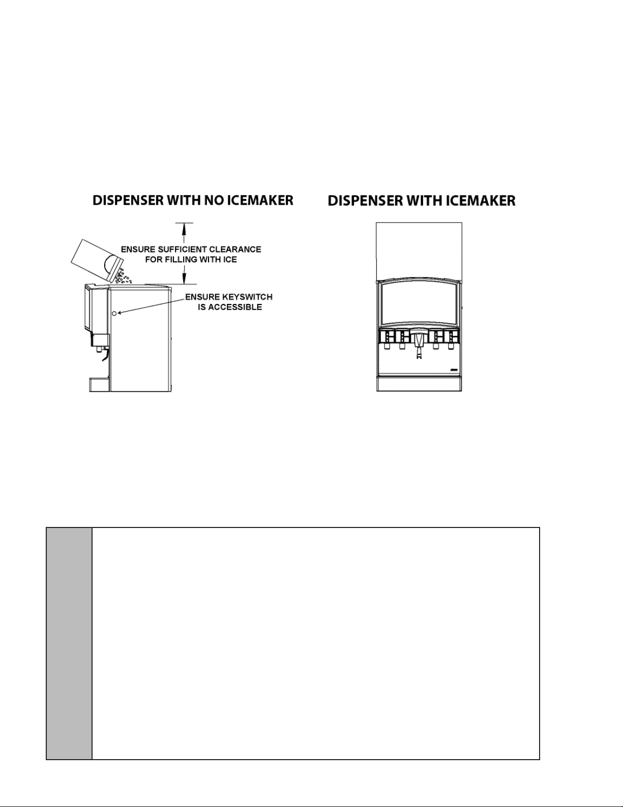
B. Sufcient clearance must be provided, if an ice maker
is not installed, to allow lling ice compartment from
a ve gallon bucket (a minimum of 16 inches is
recommended). Lancer does NOT recommend the
use of shaved or ake ice in the dispenser.
C. The selected location should be able to support the
weight of the dispenser, ice and possibly an ice
maker being installed after counter cut out is made.
Total weight (with icemaker) for this unit could exceed
800 pounds (363.6kg).
D. Unit may be installed directly on countertop or on legs.
If installed directly on the counter, unit must be sealed
to the countertop with an FDA approved sealant. If an
icemaker is to be mounted on top of dispenser, do not
install dispenser on legs.
E. Ensure there is a convenient location for placement of
the remote pump deck and that the probe extension
cord is long enough to extend to the unit.
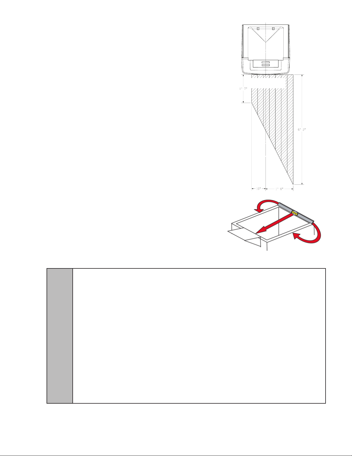
1.5 LEVELING THE DISPENSER
In order to facilitate proper dispenser drainage, ensure
that the dispenser is level, front to back and side to side.
Place a level on the top of the rear edge of the dispenser.
The bubble must settle between the level lines. Repeat
this procedure for the remaining three sides. Level unit if
necessary. For optimum performance place the unit at a
0° tilt. The maximum tilt is 5°.
1.6 INSTALLING AN ICEMAKER
Front of Unit
!
WARNING WHEN INSTALLING AN ICEMAKER ON THE DISPENSER, USE A BIN THERMOSTAT TO CONTROL THE
ICE LEVEL (SEE BELOW). THIS WILL PREVENT DAMAGE TO THE DISPENSING MECHANISM. THE BRACKET
FOR MOUNTING A THERMOSTAT IS LOCATED IN THE ICE BIN. DURING THE AUTOMATIC AGITATION CYCLE AND
WHILE DISPENSING ICE, ENSURE THERE IS ADEQUATE SPACE BETWEEN THE TOP OF THE ICE LEVEL AND
THE BOTTOM OF THE ICEMAKER SO THE ICE CAN MOVE WITHOUT OBSTRUCTION. CONTACT YOUR ICEMAKER
MANUFACTURER FOR INFORMATION ON A SUITABLE BIN THERMOSTAT.
ADVERTENCIA CUANDO INSTALA UNA MÁQUINA DE CUBITOS EN EL DISPENSADOR, USE UN TERMOSTATO DE
RECIPIENTE PARA CONTROLAR EL NIVEL DE HIELO (VER MÁS ABAJO). DE ESTA FORMA SE EVITAN LOS DAÑOS
AL MECANISMO DISPENSADOR. EL SOPORTE PARA MONTAR EL TERMOSTATO ESTÁ EN EL RECIPIENTE DEL
HIELO. DURANTE EL CICLO AUTOMÁTICO DE AGITACIÓN Y CUANDO SE DISPENSA HIELO, ASEGÚRESE DE QUE
HAYA ESPACIO ADECUADO ENTRE LA PARTE SUPERIOR DEL NIVEL DE HIELO Y LA PARTE INFERIOR DE LA
MÁQUINA DE CUBITOS, DE MODO QUE EL HIELO SE MUEVA SIN OBSTRUCCIONES. COMUNÍQUESE CON EL
FABRICANTE DE SU MÁQUINA DE CUBITOS PARA OBTENER INFORMACIÓN SOBRE UN TERMOSTATO DE
RECIPIENTE ADECUADO.
AVERTISSEMENT LORS DE L’INSTALLATION D’UN APPAREIL À CUBES DE GLACE SUR LE DISTRIBUTEUR,
UTILISEZ UN THERMOSTAT DE BAC POUR CONTRÔLER LE NIVEAU DE GLACE (VOIR CI-DESSOUS). CECI
EMPÊCHERA LES DOMMAGES AU MÉCANISME DE DISTRIBUTION. LE SUPPORT POUR FIXER UN THERMOSTAT
SE TROUVE DANS LE BAC DE GLACE. PENDANT LE CYCLE D’AGITATION AUTOMATIQUE ET LORS DE LA
DISTRIBUTION DE LA GLACE, ASSUREZ-VOUS QU’IL Y A ASSEZ D’ESPACE ENTRE LE DESSUS DU NIVEAU DE
GLACE ET LE FOND DE L’APPAREIL À CUBES DE GLACE, POUR QUE L’APPAREIL À CUBES DE GLACE PUISSE
BOUGER SANS OBSTRUCTION. CONTACTEZ VOTRE FABRICANT D’APPAREILS À CUBES DE GLACE POUR
OBTENIR DES INFORMATIONS SUR UN THERMOSTAT DE BAC APPROPRIÉ.
CONTINUED ON NEXT PAGE.....
11
Page 12
1.6 INSTALLING AN ICEMAKER (CONTINUED)
A. Install the icemaker per manufacturer specications. Points of consideration include drainage,
ventilation, and drop zones.
B. An adapter plate is required when installing an icemaker. Contact your Sales Representative or
Lancer Customer Service for more information.
C. A bin thermostat is required in order to control the level of ice in the dispenser (Refer to
WARNING on previous page). Contact your icemaker manufacturer to obtain the correct bin
thermostat. Bin thermostat should be a minimum of 2” below the top edge of the dispenser. The
preferred location of the bin thermostat is on the right side wall above the auger.
D. Ensure the icemaker is installed properly to allow for removal of the Merchandiser.
E. Ensure manual ll is accessible.
F. Clean and maintain icemaker per manufacturer’s instructions.
1.7 ADA STANDARDS FOR ACCESSIBLE DESIGN
To assure that beverage service is accessible to all customers, Lancer recom- mends that counter
height and equipment selection be planned carefully. The 2010 ADA Standards for Accessible
Design states that the maximum reach height from the oor should be no more than 48” if
TouchPoint is less than 10” from the front of the counter, or a maximum of 46” if the TouchPoint is
more than 10” and less than 27” from the front of the counter. For more information about the
customer’s legal requirements for the accessibility of installed equipment, refer to 2010 ADA
Standards for Accessible Design - http://www.ada.gov.
1.8 CONNECTING TO ELECTRICAL POWER
GROUNDING WARNING THE DISPENSER MUST BE PROPERLY ELECTRICALLY GROUNDED TO AVOID
SERIOUS INJURY OR FATAL ELECTRICAL SHOCK. THE POWER CORD HAS A THREE-PRONG GROUNDED
PLUG. IF A THREE-HOLE GROUNDED ELECTRICAL OUTLET IS NOT AVAILABLE, USE AN APPROVED METHOD TO
GROUND THE UNIT. FOLLOW ALL LOCAL ELECTRICAL CODES WHEN MAKING CONNECTIONS. EACH
DISPENSER MUST HAVE A SEPARATE ELECTRICAL CIRCUIT. DO NOT USE EXTENSION CORDS. DO NOT
CONNECT MULTIPLE ELECTRICAL DEVICES ON THE SAME OUTLET.
ADVERTENCIA, PUESTA A TIERRA ES NECESARIO PONER A TIERRA ELÉCTRICAMENTE EL
DISPENSADOR PARA EVITAR LESIONES GRAVES E INCLUSO ELECTROCHOQUES FATALES. EL CABLE DE
ALIMENTACIÓN TIENE UN ENCHUFE PUESTO A TIERRA DE 3 CLAVIJAS. SI NO SE DISPONE DE UN TOMA
ELÉCTRICO CONECTADO A TIERRA DE TRES AGUJEROS, USE UN MÉTODO APROBADO PARA PONER A TIERRA
LA UNIDAD. AL HACER LAS CONEXIONES, RESPETE TODOS LOS CÓDIGOS ELÉCTRICOS LOCALES. CADA
F
DISPENSADOR DEBE TENER UN CIRCUITO ELÉCTRICO INDEPENDIENTE. NO USE CABLES DE EXTENSIÓN. NO
CONECTE VARIOS DISPOSITIVOS ELÉCTRICOS AL MISMO TOMACORRIENTE.
EXIGENCES DE MISE À LA TERRE LA DISTRIBUTRICE DOIT ÊTRE MISE À LA TERRE ÉLECTRIQUEMENT
CORRECTEMENT POUR ÉVITER DES BLESSURES GRAVES OU UNE DÉCHARGE ÉLECTRIQUE MORTELLE. LE
CORDON D’ALIMENTATION A UNE FICHE À TROIS BRANCHES MISE À LA TERRE. SI AUCUNE PRISE DE
COURANT ÉLECTRIQUE À TROIS TROUS N’EST DISPONIBLE, UTILISEZ UNE MÉTHODE APPROUVÉE POUR
METTRE L’UNITÉ À LA TERRE. RESPECTEZ TOUS LES CODES ÉLECTRIQUES LOCAUX LORSQUE VOUS FAITES
DES CONNEXIONS. CHAQUE DISTRIBUTRICE DOIT AVOIR UN CIRCUIT ÉLECTRIQUE SÉPARÉ. N’UTILISEZ PAS
DE CORDONS PROLONGATEURS. NE BRANCHEZ PAS PLUSIEURS APPAREILS ÉLECTRIQUES À LA MÊME PRISE
DE COURANT.
12
Page 13

1.8 CONNECTING TO ELECTRICAL POWER (CONTINUED)
A. Review the warnings.
B. Route the power supply cord to a grounded electrical outlet of the proper voltage and
amperage rating.
C. Do not plug in the unit at this time.
1.9 CONNECTING TO WATER SUPPLY LINES
A. Use a sharp knife, razor blade, or tube cutter to cut tubing. Tubing cut with a saw will result in
plastic shavings which will plug the ow controls in the dispensing valve.
B. Provide an adequate potable water supply. Water pipe connections and xtures directly
connected to potable water supply must be sized, installed, and maintained according to
federal, state, and local laws. An adequate potable water supply must be provided. It is
recommended that the supply shut-off is easily accessible. The water supply line must be at
least a 3/8 inches (9.525 mm) pipe with a minimum of 20 PSI (137.9 kPa) line pressure, but
not exceeding a maximum of 50 PSI (344.74 kPa). Water pressure exceeding 50 PSI (344.74
kPa) must be reduced to 50 PSI (344.74 kPa) with a pressure regulator. Use a lter in the
water line to avoid equipment damage and beverage off-taste. A FILTER of at least 100 mesh
[100 strands per 25mm (one inch)] shall be installed immediately upstream of all check valve
type backow preventers used for water supply protection. The screen shall be accessible and
removable for cleaning or replacement.Check the water lter periodically, as required by local
conditions. The water supply must be protected by means of an air gap, a backow
prevention device (located upstream of the CO2 injection sys- tem) or another approved
method to comply with NSF standards. A leaking inlet water check valve will allow carbonated
water to ow back through the pump when it is shut off and contaminate the water supply.
Ensure the backow prevention device complies with ASSE and local standards. Do not
connect to a heated (hot) water source or a water source supplying soft water. This will cause
excessive foaming.
C. It is the responsibility of the installer to ensure compliance..
1.10 CONNECTING TO CO2 (REFER TO ELECTRICAL WARNING ON PAGE 7)
A. Provide a regulated CO2 supply to the dispenser through a 3/8 inch supply line. The maximum
pressure is 80 PSI.
WARNING! EXCESSIVE CO2 PRESSURE CAN DAMAGE COMPONENTS
1.11 INSTALLATION OF THE UNIT AND PUMP DECK
A. Inspect the counter location where the unit is to be installed. verify that the counter is strong
enough to safely support the weight of the unit being installed (see Section 1.4), after the cutout
for the unit is made.
B. Position the pump deck within as close proximity to the dispenser as possible. The pump deck
must be on a level surface and have adequate utilities available. Ensue that the pump deck
switch is set to the OFF position.
C. Install a shut-off valve in the water line feeding the deck. If a separate water line is run for plain
water, ensure that it also has a shut-off valve.
D. The carbonator pump is equipped with a strainer on the inlet side. Failure to install or maintain
the water lter may starve the pump of water, causing it to burn out, and voiding the warranty.
E. Position the CO2 gas tank in a serviceable location. Assembly the high pressure regulator to
the CO2 gas tank and run the jumper line to the low pressure regulator.
F. Attach the CO2 gas line to the carbonator by attaching the line from the high pressure regulator
to the CO2 inlet located at the front of the unit. The setting of the high pressure CO2 gas
regulator should be 75 psi. DO NOT turn on CO2 at this time.
G. If required, install water booster (Lancer PN 82-3401 or MC-163172) between water supply and
unit.
H. Tee off outbound water line, run one line to the plain water inlet at the front of the dispenser and
one to the remote pump deck inlet regulator. Reference plumbing diagram on front of unit for
plain water inlet tting location.
I. Complete the carbonated water line connection between the remote pump deck and
carbonated water inlet on the dispenser. Reference plumbing diagram on front of unit for
carbonated water inlet tting location.
13
CONTINUED ON NEXT PAGE.....
Page 14

1.11 INSTALLATION OF THE UNIT AND PUMP DECK (CONTINUED)
J. Connect syrup supply lines to the 3/8 inch barb inlet ttings at the front of the unit. Reference
plumbing diagram on front of unit. Primary syrup valve is S1.
K. Connect the avor injection lines to the barb ttings at the front of the unit. Reference plumbing
diagram on front of unit.
L. Connect the hose to the Drip Tray tting, install the Drip Tray, and extend hose to open type
drain.
M. Both drain lines must be insulated with a closed cell insulation. Insulation must cover the entire
length of the drain hose, including ttings. The drain should be installed in such a manner that
water does not collect in sags or other low points, as condensation will form.
1.12 CHECKING FOR LEAKS
A. Turn on water. Open the pressure relief valve on the carbonator tank by ipping up the valve
cap lever, and hold it open until water ows from the relief valve. Close (ip down) the relief
valve.
B. Verify Bag-In-Box contains syrup.
C. Check all connections for leaks.
1.13 PRE-INSTALL
NOTE: Prior to plugging in the unit, ensure there are no ash drives insertted in any of the USB
ports on CPU
A. Connect Power Cord to grounded electrical outlet.
B. TouchPoint will begin booting up as soon as power is connected. Boot-up may take several
minutes. Cup selection carrousel will appear when complete.
C. Test Motor operation by pushing Ice Chute until the agitation motor begins to turn.
D. Utilize the TECHNICIAN MENU valve actuators when valve actuation is required.
E. To access the TECHNICIAN MENU, turnkey switch one position in the clockwise direction to
access the MAIN MENU.
F. Select the TECHNICIAN MENU button.
14
Page 15

G. Contact Lancer Warranty for the default pass-code or ask store manager if pass code was
changed.
H. During sanitizing, use only the MANUAL POUR button on each valve.
I. Clean and sanitize the entire dispenser prior to proceeding. Follow sanitizing instructions in
Section 2.
15
Page 16

1.14 CARBONATOR AND SYRUP PURGING
A. Ensure CO2 supply is turned OFF.
B. Ensure the pump deck is turned OFF.
C. Open the relief valve until water comes out. Close
the relief valve.
D. Access the TECHNICIAN MENU.
E. To ll plain water and carbonated water lines,
ensure a good ow of water is established when
pouring from the PLAIN WATER and CARB
WATER valve modules.
F. Turn on CO2 at source and ensure the
regulator is set at 75 PSIG and that the
remote carbonator deck is switched to the OFF
position.
G. Turn the remote carbonator deck switch to the ON
position.
H. Dispense soda water until the carbonator pump
comes on. Release the button, allow the
carbonator to ll and stop (usually a few seconds). Repeat this process until the water is
carbonated (about 5 cycles).
NOTE: The pump deck has a 3 minute timeout feature. If the timeout occurs, turn the deck OFF
then ON by ipping the switch on the control box.
NOTE: To check for CO2 leaks, close the valve on the CO2 cylinder and observe if the pressure
to the system drops with the cylinder valve closed for ve minutes. Open the cylinder valve after
check.
I. Ensure the low pressure regulator is at 65 PSIG for syrup lines. Activate each MANUAL POUR
button each syrup and avor valve module to purge air from syrup lines.
1.15 SETTING UP BRANDS
A. Access the TECHNICIAN MENU.
B. Deactivate any syrup or avor adder valve module not being used by tapping the colored ribbon
at the top of the module:
NOTE: The cup associated with each syrup
module deactivated will appear with a “SOLD
OUT” icon in the cup carrousel and will not be
selectable. The avor adder icons associated
with each avor adder module will no longer
appear in the Pour screen.
16
Page 17

C. For each syrup and avor adder module being used, tap the brand icon to open the Brand
Library and reveal additional syrup brands for selection.
D. Selecting the different tabs on the left side of the screen will reveal even more available
brands. Tap BACK to return to TECHNICIAN MENU.
17
CONTINUED ON NEXT PAGE.....
Page 18

1.15 SETTING UP BRANDS (CONTINUED)
E. Tap the desired syrup brand. Selected brand will become darker. Tap SAVE to change
assignment. Tap CANCEL to remove selection.
F. Modify the DISPENSE FLOW RATE and W/O ICE RATIO if required. Ratios and dispense
times will automatically be updated when changes are applied.
18
Page 19

G. After completing changes, tap SAVE to apply all changes made. Tapping CANCEL will undo
ALL unsaved changes.
1.16 FILLING ICE AND SETTING RATIO
A. Fill unit with ice until the auger is covered. Push Chute and check for ice delivery.
B. Finish lling the unit with ice and install Top Cover (if applicable).
C. To set the ratio, access the TECHNICIAN MENU.
D. Valve ow controls still need to be manually adjusted.
E. No syrup separator is required. Utilize the graduated cylinder provided in installation kit.
F. Place the graduated cylinder under the nozzle and tap TIME POUR.
G. Check the amount of liquid captured in the graduated cylinder and compare to value displayed
onscreen. Tap DISMISS to return to valve modules.
H. Adjust ow control and repeat until required volume dispensed.
I. Repeat this for all modules on the screen.
J. When complete, tap BACK button to return to MAIN MENU.
K. Turn key switch back to NORMAL RUN position.
L. Install these items in the following order: 1) Side Panels, 2) Drip Tray/Cup Rest, 3)Splashplate
NOTE: Reconnect the wires, 4) Merchandiser, 5) Ice Chute Lever.
19
Page 20

1.17 OTHER
A. Pouring hot water into drain may cause the Drain Tube to collapse.
Allow only luke warm or cold water to enter Drain Tube.
B. Pouring coffee tea and similar substances into drain may cause
the Drain Tube to become clogged with coffee or tea grounds, or
other solid particles.
C. If an icemaker is not installed on the unit, it is required to leave at
least 6 to 8 inches of clearance from the top of the bin to the ice line.
This ensures the lid will not be displaced due to the ice shifting during
agitation.
2. CLEANING AND SANITIZING INSTRUCTIONS
A. The cleaning and sanitizing procedures provided herein pertain to the Lancer equipment
identied by this manual. If other equipment is being cleaned, follow the guidelines established
by the manufacturer for that equipment.
B. Lancer equipment is shipped from the factory cleaned and sanitized in accordance with NSF
guidelines. The equipment must be cleaned and sanitized after installation is complete. The
operator of the equipment must provide continuous maintenance as required by this manual
and both state and local health department guidelines to ensure proper operation/sanitation
requirements are maintained.
C. Cleaning and sanitizing should be accomplished only by trained personnel. Sanitary gloves are
to be used during cleaning and sanitizing operations. Applicable safety precautions must be
observed. Instruction warnings on the product used must be followed.
2.1 CLEANING AND SANITIZING SOLUTIONS
WARNING IF A POWDER SANITIZER IS USED, DISSOLVE IT THOROUGHLY WITH HOT WATER PRIOR TO
ADDING TO THE SYRUP SYSTEM. ENSURE SANITIZING SOLUTION IS REMOVED FROM THE DISPENSER AS
INSTRUCTED. AVOID GETTING SANITIZING SOLUTION ON CIRCUIT BOARDS. DO NOT USE STRONG BLEACHES
OR DETERGENTS; THESE CAN DISCOLORAND CORRODE VARIOUS MATERIALS. DO NOT USE METAL
SCRAPERS, SHARP OBJECTS, STEEL WOOL, SCOURING PADS, ABRASIVES, OR SOLVENTS ON THE
DISPENSER. DO NOT USE HOT WATER ABOVE 140° F (60° C). THIS CAN DAMAGE THE DISPENSER.
ADVERTENCIA SI SE USA UN HIGIENIZADOR EN POLVO, DISUÉLVALO BIEN EN AGUA ANTES DE AGREGARLO
AL SISTEMA DE CONCENTRADO. EL USO DE AGUA CALIENTE CONTRIBUYE A DISOLVER LOS HIGIENIZADORES
EN POLVO. ASEGÚRESE DE HABER ELIMINADO LA SOLUCIÓN DE ESTERILIZACIÓN DEL DISPENSADOR DE
ACUERDO CON LAS INSTRUCCIONES. LOS RESIDUOS DE LA SOLUCIÓN DE ESTERILIZACIÓN REPRESENTAN
UN PELIGRO PARA LA SALUD. EVITE QUE LA SOLUCIÓN DE ESTERILIZACIÓN LLEGUE A LAS PLACAS DE
CIRCUITOS. NO USE LAVANDINAS NI DETERGENTES QUE PODRÍAN QUITAR EL COLOR Y CORROER DISTINTOS
!
MATERIALES. NO USE RASPADORES METÁLICOS, OBJETOS FILOSOS, LANA DE ACERO, ESTROPAJOS,
ABRASIVOS NI SOLVENTES EN EL DISPENSADOR. NO USE AGUA CALIENTE A MÁS DE 140 ºF (60 ºC). PODRÍA
DAÑAR EL DISPENSADOR.
AVERTISSEMENT AVANT L’INJECTION DANS LE SYSTÈME, IL FAUDRA QUE LA POUDRE SEPTIQUE SOIT
DISSOLUE ENTIÈREMENT DANS CHAUDE. L’EAU CHAUDE PERMETTRA UN MEILLEUR PROCÈS DE
DISSOLUTION. SUIVANT LES INSTRUCTIONS JOINTES, IL EST IMPÉRATIF QUE LA SOLUTION SEPTIQUE SOIT
ENTIÈREMENT ENLEVÉE. EVITEZ DE METTRE LA SOLUTION EN CONTACT AVEC LES CIRCUITS. N’UTILISEZ PAS
DE JAVELLISANTS OU DEDÉTERGENTS FORTS; CEUX-CI PEUVENT DÉCOLORER ET CORRODER DIVERS
MATÉRIAUX. N’UTILISEZ PAS DE RACLEURS EN MÉTAL, D’OBJETS POINTUS, DE LAINE D’ACIER, DE TAMPONS À
RÉCURER, D’ABRASIFS OU DE SOLVANTS SUR LE DISTRIBUTEUR. N’UTILISEZ PAS DE L’EAU CHAUDE DE PLUS
DE 140 DEGRÉS F (60 DEGRÉS C). CECI PEUT ENDOMMAGER LE DISTRIBUTEUR.
CLEANING SOLUTION: Mix a mild, non-abrasive detergent (e.g. Sodium Laureth Sulfate, dish
soap) with clean, potable water at a temperature of 90 to 110°F (32 to 43°C). The mixture ratio is
one ounce of cleaner to two gallons of water. Prepare a minimum of ve gallons of cleaning
solution. Do not use abrasive cleaners or solvents because they can cause permanent damage to
the unit. Rinsing must be thorough, using clean, potable water at a temperature of 90 to 110°F (32
to 43°C). Extended lengths of product lines may require that an additional volume of cleaning
solution is prepared.
SANITIZING SOLUTION: Prepare sanitizing solutions in accordance with the manufacturer’s
written recommendations and safety guidelines. The solution must provide 200 parts per million
(PPM) chlorine (e.g. Sodium Hypochlorite or bleach). A minimum of ve gallons of sanitizing
solution should be prepared. Any sanitizing solution may be used as long as it is prepared in
accordance with the manufacturer’s written recommendations and safety guidelines, and provides
200 parts per million (PPM) chlorine. Extended lengths of product lines may require that an
additional volume of sanitizing solution be prepared.
20
Page 21

2.1 CLEANING AND SANITIZING SOLUTIONS (CONTINUED)
NOZZLE SANITIZING SOLUTION: Prepare a chlorine solution (less than pH 7.0) containing 50
PPM chlorine with clean, potable water at a temperature of 90 – 110°F. Any sanitizing solution may
be used as long as it is prepared according to manufacturer’s recommendations and safety guidelines, and provides 50 PPM cholorine.
OTHER SUPPLIES NEEDED: 1) Clean cloth towels; 2) Bucket; 3) Extra nozzle; 4) Sanitary gloves;
5) Small brush (PN 22-0017)
2.2 DAILY CLEANING
A. Using the cleaning solution, clean Top Cover and all exterior stainless steel surfaces.
B. Clean exterior of dispensing valves and ice chute.
C. Remove Cup Rest, clean Drip Tray and Cup Rest, and replace Cup Rest.
D. Wipe clean all splash areas using a damp cloth soaked in cleaning solution.
E. Clean beverage valves as specied by the valve manufacturer.
2.3 ICE BIN CLEANING - START UP AND MONTHLY
(REFER TO THE AUTOMATIC AGITATION WARNING ON PAGE 8)
A. Disconnect power to the dispenser
B. Remove Top Cover.
C. Melt out any remaining ice from the bin.
D. Remove Agitator Pin from Agitator Shaft. Slide Agitator Shaft rearward out Hub and pull out of
rear Bearing to remove.
E. Remove Ice Shroud by lifting and rotating out from beneath the auger.
F. Use the Cleaning Solution described in Section 3.1, and a clean cloth or soft brush, to clean all
removable parts, sides of the Ice Bin, Auger, and surface of the aluminum casting.
G. Using the Cleaning Solution and the sponge brush provided, clean all interior surfaces of the
ice chute and the ice chute feed through.
H. Repeat Step F for all exterior surfaces of the dispenser.
I. Using hot water, thoroughly rinse away the cleaning solution.
J. Wearing sanitary gloves, soak and clean cloth towel in Sanitizing Solution, described in
Section 3.1, and wash all surfaces of removable parts, sides of the Ice Bin, Auger, and surface
of the aluminum casting.
K. Using the Sanitizing Solution and the sponge brush provided, clean all interior surfaces of the
ice chute and the ice chute feed through.
L. Repeat step F for all exterior surfaces of the dispenser.
M. Wearing sanitary gloves, reassemble all removable parts. Ensure agitator clip is locked (See
Fig 2, Section 1.2 of Operations Manual).
N. Fill Unit with ice and replace Top Cover.
O. Reconnect Dispenser to power source.
2.4 CLEANING AND SANITIZING BEVERAGE COMPONENTS - FIGAL SYSTEMS
WARNING TO AVOID POSSIBLE PERSONAL INJURY OR PROPERTY DAMAGE, DO NOT ATTEMPT TO REMOVE
SYRUP TANK COVER UNTIL CO2 HAS BEEN RELEASED FROM TANK.
ADVERTENCIA PARA EVITAR POSIBLES LESIONES PERSONALES O DAÑOS MATERIALES, NO TRATE DE
RETIRAR LA TAPA DEL TANQUE DE SOROPE HASTA QUE SE HAYA LIBERADO LA PRESIÓN DEL CO2 DEL
TANQUE.
5
AVERTISSEMENT POUR ÉVITER DES BLESSURES OU DES DOMMAGES MATÉRIELS POSSIBLES, N’ESSAYEZ
PAS DE RETIRER LE COUVERCLE DU RÉSERVOIR DE SIROP, JUSQU’A CE QUE DE LA PRESSION DE CO2 AIT
ÉTÉ LIBÉRÉE DU RESERVOIR.
NOTE: Extended lengths of product lines may require more time for ushing and rinsing lines than
stated below.
A. Disconnect syrup lines from syrup containers (for example, quick disconnects, gal containers,
etc.).
B. Connect hose half of syrup line to a syrup tank lled with clean, potable, room temperature
water. Connect CO2 supply hose to tank and pressurize.
CONTINUED ON NEXT PAGE.....
21
Page 22

2.4 CLEANING AND SANITIZING BEVERAGE COMPONENTS - FIGAL SYSTEMS (CONTINUED)
C. Turn key switch to SERVICE position. Using the TECHNICIAN MENU, activate valve until water
is dispensed. NOTE: To activate a valve, access the Technician’s Menu. Refer to ‘Basic Set Up
& User Guide’ for instructions to access the Technician’s Menu. Diagram 2.1.3 maps each
feature of the valve modules dis- played. The diagram shown in 2.2.1 instructs how to actuate a
pour from each valve.
D. Flush and rinse line and ttings for a minimum of 60 seconds to remove all traces of residual
product.
E. Disconnect CO2 supply hose from the water lled syrup tank.
F. Prepare sanitizing solution for unit as described in section 2.1. Fill a tank with this solution.
Connect hose half of syrup line to the tank. Connect CO2 supply hose to tank and pressurize.
G. Using the TECHNICIAN MENU, activate valve and draw cleaning solution through lines for a
minimum of 60 seconds. This will ensure line is ushed and lled with cleaning solution. Allow
line to stand for at least 30 minutes.
CAUTION FOLLOWING SANITIZATION, RINSE WITH END-USE PRODUCT UNTIL THERE IS NO AFTERTASTE. DO
NOT USE A FRESH WATER RINSE. THIS IS A NSF REQUIREMENT. RESIDUAL SANITIZING SOLUTION LEFT IN THE
SYSTEM CREATES A HEALTH HAZARD.
PRECAUCIÓN DESPUÉS DE LA ESTERILIZACIÓN, ENJUAGUE CON EL PRODUCTO FINAL HASTA QUE
ELIMINAR EL SABOR QUE QUEDA. NO ENJUAGUE CON AGUA FRESCA. ÉSTA ES UNA EXIGENCIA DE NSF. SI
!
H. Prepare nozzle sanitizing solution as described in section 2.1.
I. Turn key switch to “VALVE OFF” position, two positions counter clockwise, to avoid accidental
J. Remove the outer nozzle by twisting clockwise and pulling downward. DO NOT attempt to
activate any vlaves while the outer nozzle is removed.
K. Wash outer nozzle with cleaning solution.
L. Immerse the outer nozzle in a bath of the nozzle sanitizing solution for 15 minutes.
M. While the outer nozzle is in the sanitizing solution, using the nozzle brush provided in the
installation kit, dip the brush in the sanitizing solution and thoroughly brush the bottom of the
N. Rinse the brush in warm 90 – 110°F, clean potable water and brush the bottom of the inner
O. After the outer nozzle has soaked for 15 minutes, rinse in warm 90 - 110°F, clean potable water
P. Allow outer nozzle to air dry (to expedite drying, forced convection is recommended).
Q. Reinstall the outer nozzle to the unit.
R. Return the key switch position to the SERVICE position and return to the TECHNICIAN MENU.
S. Disconnect CO2 supply hose from the tank.
T. Connect hose half of syrup line to a tank lled with clean, potable, water at a temperature of 90°
U. Activate valve to ush and rinse line and ttings for a minimum of 60 seconds to remove all
V. Disconnect CO2 supply hose from the tank.
W. Reconnect syrup lines to syrup containers (for example, quick disconnects, gal containers,
X. Draw drinks to rell lines and ush the sanitizing solution from the dispenser.
Y. Test dispenser in normal manner for proper operation. Taste dispensed product to ensure there
Z. Repeat cleaning, rinsing, and sanitizing procedures for each valve and each circuit.
QUEDA SOLUCIÓN DE ESTERILIZACIÓN EN EL SISTEMA, GENERA UN PELIGRO PARA LA SALUD.
ATTENTION DÉFENSE DE RINCER L’OUTIL À L’EAU FRAICHE IMMÉDIATEMENT APRÈS UN TRAITEMENT
SEPTIQUE.EN CAS DE APRÈS-GOÛT, NE PURGER AVEC LE PRODUIT FINAL UNE EXIGENCE NSF.
dispense while the nozzle is exposed. This will Exit the TECHNICIAN MENU screen and return
to the Cup Carrousel screen.
inner nozzle body.
nozzle body once more WITHOUT the sanitizing solution.
for a minimum of 20 seconds ensuring all surfaces of the nozzle have been thoroughly rinsed.
to 110°F. Connect CO2 supply hose to tank and pressurize.
traces of cleaning solution. Taste dispensed product to ensure there is no off-taste. If off-taste is
found, additional ushing of syrup system may be required.
etc.) and ready unit for operation.
is no off-taste. If off-taste is found, additional ushing of syrup system may be required.
22
Page 23

2.5 CLEANING AND SANITIZING BEVERAGE COMPONENTS - BAG-IN-BOX SYSTEMS
NOTE: Extended lengths of product lines may require more time for ushing and rinsing lines than
described below.
A. Disconnect the syrup quick disconnect coupling from the syrup packages and connect the
coupling to a bag valve removed from an empty Bag-in-Box (BIB) package.
B. Place the syrup inlet line in a clean container lled with clean, potable, room temperature water.
C. Activate valve until water is dispensed. NOTE: To activate a valve, access the Technician’s
Menu. Refer to ‘Basic Set Up & User Guide’ for instructions to access the Technician’s Menu.
Diagram 2.1.3 maps each feature of the valve modules displayed. The diagram shown in 2.2.1
instructs how to actuate a pour from each valve.
D. Flush and rinse line and ttings for a minimum of 60 seconds to remove all traces of residual
product.
E. Prepare sanitizing solution for unit as described in section 2.1. Place syrup inlet line in
container lled with cleaning solution.
F. Activate valve and draw cleaning solution through lines for a minimum of 60 seconds. This will
ensure line is ushed and lled with cleaning solution. Allow line to stand for at least
30 minutes.
G. Prepare nozzle sanitizing solution as described in section 2.1.
H. Turn key switch to “VALVE OFF” position, two positions counter clockwise, to avoid accidental
dispense while the nozzle is exposed. This will Exit the TECHNICIAN MENU screen and return
to the Cup Carrousel screen.
I. Remove the outer nozzle by twisting clockwise and pulling downward. DO NOT attempt to acti
vate any vlaves while the outer nozzle is removed.
J. Wash outer nozzle with cleaning solution.
K. Immerse the outer nozzle in a bath of the nozzle sanitizing solution for 15 minutes.
L. While the outer nozzle is in the sanitizing solution, using the nozzle brush provided in the
installation kit, dip the brush in the sanitizing solution and thoroughly brush the bottom of the
inner nozzle body.
M. Rinse the brush in warm 90 – 110°F, clean potable water and brush the bottom of the inner
nozzle body once more WITHOUT the sanitizing solution.
N. After the outer nozzle has soaked for 15 minutes, rinse in warm 90 - 110°F, clean potable water
for a minimum of 20 seconds ensuring all surfaces of the nozzle have been thoroughly rinsed.
O. Allow outer nozzle to air dry (to expedite drying, forced convection is recommended).
P. Reinstall the outer nozzle to the unit.
Q. Return the key switch position to the SERVICE position and return to the TECHNICIAN MENU.
R. Place syrup inlet line in a clean container lled with clean, potable, water at a temperature of
90° to 110°F.
S. Activate valve to ush and rinse line and ttings for a minimum of 60 seconds to remove all
traces of cleaning solution.
T. Remove bag valve from quick disconnect coupling and reconnect syrup inlet line to syrup pack
age. Ready unit for operation.
U. Draw drinks to rell lines and to ush the chlorine sanitizing solution from the dispenser.
V. Test dispenser in normal manner for proper operation. Taste dispensed product to ensure there
is no off-taste. If off-taste is found, additional ushing of syrup system may be required.
W. Repeat cleaning, rinsing, and sanitizing procedures for each valve and each circuit.
2.6 TO ACCESS SERVICE AREA
NOTE: Service area should only be accessed by trained personnel.
A. Remove outer nozzle. Twist clockwise and pull down.
B. Remove cup rest and ice chute lever.
C. Remove Splash Plate. Take care to disconnect cable connected to back of ADA membrane
switch board.
D. Remove screws holding merchandiser in place.
E. Remove Merchandiser.
F. After service, reinstall items.
23
Page 24

2.7 ICE CHUTE CLEANING
It is recommended to perform this procedure monthly, or more often if desired. Use the
cleaning solution described above. An alternate solution of one part water to one part vinegar may be used to remove water spots and calcium deposits.
A. Turn off power to the dispenser.
B. Remove Merchandiser.
C. Remove Ice Chute Lever, then remove Splash Plate Assembly by lifting it up and out from the
dispenser face. NOTE: Always remove the ice chute lever before removing the splash plate.
D. Remove clip from Auger Motor Shaft. Remove four (4) screws from brackets. Ensure Motor
Harness is disconnected and retain the auger shaft key.
F. Remove the Ice Chute Assembly base by removing the four (4) screws that attach it to the unit.
G. Prepare the Cleaning Solution described in Section 3.1.
H. Soak the Ice Chute Assembly in the solution.
I. Rinse and dry the Ice Chute Assembly thoroughly.
J. Reinstall the Ice Chute Assembly.
K. Reinstall Merchandiser and Splash Plate.
L. Reconnect power to the dispenser.
2.8 REMOVAL OF ICE CHUTE FOR SERVICE
A. Disconnect power to the dispenser
B. Remove the merchandiser.
C. Disconnect the wire harness for the auger motor.
D. Remove the C-clip from the auger shaft.
E. Support the auger motor. Remove four (4) screws securing the auger motor mounting plate.
F. Slide the motor off the auger shaft. Do NOT discard the shaft key.
G. Remove the two (2) auger motor mounting plate support brackets by removing the four (4)
screws securing brackets to the mounting plate.
H. Unhook the ice chute spring from the ice chute.
I. Remove the ice chute assembly from the mounting plate by removing the screws securing it
into place.
J. Be sure to retain the o-ring from between the ice chute assembly and the feed-through.
K. Remove the outer ice chute from the base by pushing the hinge tabs inward to release the
outer ice chute.
24
Page 25

3. SOFTWARE, MULTIMEDIA & TOUCH SCREEN TROUBLESHOOTING
TROUBLE CAUSE REMEDY
3.1 Advertising mode does not
activate.
A. Object too close to the proximity sensor located on the front of the
dispenser
B. No videos uploaded
A. Remove object and ensure proper
clearances are maintained
B. Upload videos. For information on how
to upload videos, reference User Guide
28-2810.
Multi Media & Advertising
3.2 After turning on unit,
receiving error message “Remove
disks or other media. Press any
key to restart”.
3.3 After turning on the unit,
receiving a “Windows Error
Recovery” message.
3.4 System not displaying correct
date and time after adjustments.
3.5 After turning on the unit,
receiving message on touch
screen “No Video Input”.
Set Up
C. Video input selection set to HDMI.
D. Incorrect format.
A. External USB ash drive is plugged
into CPU prior to start up
A. Unit was not previously shut down
properly
A. Date and time adjustment settings
not saved after previous edits
A. Improper connection between CPU
power cables. No power to CPU.
B. Video input cables are not connected properly.
C. Incorrect software revision.
D. Malfunctioning video cables.
E. Malfunctioning CPU power supply.
F. Malfunctioning touch screen.
G. Malfunctioning CPU assembly.
C. Access Settings in Main Menu. Select
“Vide Settings” tab. Ensure “Local Video” is
green. If not, select Local Video button.
D. Reference 28-2810 TouchPoint User
Guide for proper video formatting.
A. Remove USB from CPU and press the
center button on the ADA key pad
A. Allow countdown to auto start the
software OR press the center button on the
ADA key pad
A. Adjust date and time to correct settings
and SAVE changes BEFORE exiting
A. Ensure power harnesses are properly
connected from main control box to power
bricks, and from power bricks to CPU.
B. Ensure video input cables are
connected correctly from CPU to
touchscreen.
C. Press the red button to reset the unit
and contact Lancer technical services
to determine if Windows software BIOS
should be reset.
D. Replace the video cables.
E. Replace CPU power supply.
F. Replace touch screen.
G. Replace CPU assembly.
3.6 After plugging in unit to power
outlet, no power received at the
dispenser.
3.7 Incorrect brand line up
appears in Beverage Selection
Carrousel after congurations
were completed.
A. Loose connections at the main control box.
B. Tripped breaker
A. Conguration edits were not saved A. Recongure valve modules to display
25
A. Power cord not plugged into power inlet
on control box assembly
B. Check if breaker popped out and push
back in.
correct brands and SAVE changes
BEFORE exiting
Page 26

TROUBLE CAUSE REMEDY
3.8 Touch screen not responding
to any touch inputs.
A. Loose USB connection at touch
screen or CPU.
A. Ensure all touch screen connections are
secure on touch screen and CPU.
B. CPU not reading touch screen USB.
C. Improperly shutdown
3.9 No dispense occurs when
touching the pour button or the
cup while in the Pour Screen.
Touch Screen & User Interface
3.10 No sound. A. Incorrect audio codec in video les
Sound
A. Lost communication to valve board.
B. Loose valve connection.
B. Volume level set too low.
C. Loose speaker connection or disconnected harness.
C. Malfunctioning speaker harness.
D. Malfunctioning speaker.
B. Disconnect touch screen USB from
CPU. Plug touch screen USB back into
CPU.
C. Press red reset button. Wait 5 seconds.
Press red reset button again.
A. Reset valve communication in
technician’s menu
B. Run valve diagnostic in technician’s
menu to identify if loose connection and
correct.
A. Ensure codec is correct per 28-2810
User Guide
B. Ensure volume setting is not at the
lowest setting. Increase volume as desired.
C. Ensure all speaker connections are
secure. Check harnesses at speaker and
also speaker harnesses inside control box.
C. Replace speaker harness.
D. Replace speaker assembly.
3.13 When accessing menus,
receive message ”Management
USB key required! Please plug-in
management USB-key. Then tap
CHECK Button”
Exporting Data
A. No authorized USB ash drive is
inserted in the CPU.
B. Unauthorized USB ash drive is
inserted in the CPU.
C. Authorized USB ash drive is
insert- ed in the CPU but USB
communication error is occurring.
D. Malfunctioning USB ash drive
A. Insert authorized ash drive into
available USB port on CPU box.
Authorized ash drives can be obtained by
calling Lancer Customer Service
B. File transfers can only be completed
with a Lancer provided, authorized USB
ash drive. Obtain proper ash drive and
insert into available USB port on CPU box.
C. Restart the system by using the
TERMINAL CONTROL in the main menu.
D. Replace USB ash drive
26
Page 27

TROUBLE CAUSE REMEDY
3.12 ADA keypad does not
respond to input
A. Loose or improperly connected
A. Check all cables are connected properly
from the ADA membrane switch to the ADA
control board. Ensure no exposed pins at
connections. Ensure cable is not twisted, if
it is, disconnect and properly reconnect.
ADA
3.16 Menu screen does not
appear when key switch turned
Key switch/ADA board
3.17 Auto interrupt / proximity
sensor feature not triggering when
customer approaches machine
Proximity Sensor
B. Malfunctioning ADA board
C. Malfunctioning ADA membrane
switch
A. Loose connections
B. Faulty key switch
C. Faulty ADA board
A. Proximity sensor turned off
B. Proximity sensor not included
C. Loose or improper connections
D. Faulty proximity sensor
B. Replace ADA board
C. Replace splash plate with new ADA
membrane switch
A. Check connections: ADA board to
control box for power, ensure USB cable
connected properly, ensure 4 pin connector
from key switch to ADA board connected
properly.
B. Replace key switch
C. Replace ADA board
A. Access Menu and change proximity
sensor to be turned on
B. Ensure unit has an oval window just
above the ADA keypad. If no window is
located there, unit does not have a
proximity sensor.
C. Check connections from proximity
sensor to ADA board
D. Replace proximity sensor
E. Faulty ADA board assy
E. Replace ADA board assy
27
Page 28

4. MECHANICAL TROUBLESHOOTING
TROUBLE CAUSE REMEDY
4.1 Touch screen responsive but no
product dispensed when POUR icon
is touched from avor selection/pour
screen:
No clicking can be heard from solenoid
activation
A. Unit is in “NO DISPENSE” mode
B. Valve harnesses not connected
properly
C. Carbonator pump over pressurized not
allowing solenoid to open
D. Malfunctioning solenoid valve
A. Check key switch and turn to Normal
RUN position
B. Run Solenoid Test to ensure proper
harness connection. Fix highlighted
valves if open circuit detected
C. Relieve some pressure from the CO2
relief valve and try actuating valve
E. Malfunctioning valve board(s)
4.2 Touch screen responsive but no
product dispensed when POUR icon
is touched from avor selection/pour
screen:
Clicking can be heard from solenoid
activation
4.3 Push chute and nothing happens A. Dispenser not connected to power
4.4 Push chute. Ice door opens but motor
does not run
4.5 Push chute. Motor runs but ice door
does not open.
A. Kinked line from valve to nozzle
blocking ow
source
B. Wiring harness not plugged in
C. Ice board defective
D. Malfunctioning power supply
A. Wiring harness not plugged in
B. Ice board defective
C. Motor defective
A. Solenoid not connected to ice board
B. Solenoid defective
D. Replace valve
E. Replace valve board(s)
A. Find kinked line and correct
A. Connect dispenser to power source
B. Plug in wiring harness
C. Replace ice board
D. Check voltage to power supply. Check
fuses.
A. Plug in wiring harness
B. Replace ice board
C. Replace motor
A. Connect solenoid to ice board
B. Replace solenoid
C. Ice board defective
4.6 Push chute, ice door opens, motor
runs, but no ice dispenses, or ice is of
poor quality
4.7 Water in ice bin A. Cold plate drain is obstructed A. Remove splash plate to obtain access
4.8 Water leakage around nozzle A. Damaged or improperly installed o-ring
4.9 Miscellaneous leakage A. Gasket not sealing or gap between
4.10 Noisy/cavitating carbonator pump A. Insufcient incoming water supply
A. Dispenser is out of ice
B. Agitator pin is missing or damaged
C. Poor ice quality
on nozzle
parts
B. Damaged or improperly installed
o-rings
pressure
28
C. Ice board defective
A. Fill dispenser with ice
B. Replace agitator pin
C. Service ice machine
to drain tubes and clear accordingly
A. Remove outer nozzle and check
o-rings. If damaged, replace. If improperly
installed, adjust.
A. Tighten appropriate retaining screws
B. Replace or adjust appropriate o-rings
A. Verify incoming supply water pressure
to carbonator pump is a min of 25 PSI,
max of 50 PSI
Page 29

TROUBLE CAUSE REMEDY
4.11 Insufcient soda ow (carbonated
drinks)
A. Insufcient CO2 supply pressure
B. Shutoff on mounting block is not fully
open
A. Verify incoming CO2 pressure is
between 70-75 PSI
B. Open shutoff fully
C. Foreign debris in soda ow control
D. Defective LFCV module
4.12 Insufcient water ow (plain water
drinks)
4.13 Erratic ratio A. Incoming water and/or syrup supply
A. Insufcient incoming supply pressure
B. Shutoff on mounting block not fully
open
C. Foreign debris in water ow control
D. Water ltration problem
E. Defective LFCV module
not at min owing pressure
B. Foreign debris in water and/or syrup
ow control
C. Remove soda ow control from valve
and clean out any foreign material to
ensure smooth spool movement
D. Replace module
A. Verify incoming supply water pressure
to plain water inlet is a min of 75 PSI,
max of 125 PSI
B. Open shutoff fully
C. Remove water ow control from valve
and clean out any foreign material to
ensure smooth spool movement
D. Service water system as required
E. Replace module
A. Check pressure and adjust
B. Remove ow control from suspected
valve and clean out any foreign material
to ensure smooth spool movement
C. CO2 regulator malfunction
4.14 Insufcient syrup ow A. Insufcient CO2 pressure to BIB
pumps
B. Shutoff on mounting block not fully
open
C. Foreign debris in syrup ow control
D. Defective BIB pump
4.15 Valve will not shut off A. Debris in solenoid seat
B. Solenoid plunger sticking
4.16 Water continually leaking at
connections
A. Loose water connections
C. Repair or replace CO2 regulator
A. Adjust CO2 pressure to BIB pumps
to 80 PSI (min. 70 PSI). Do not exceed
manufacturer’s recommendations
B. Open shutoff fully
C. Remove syrup ow control from valve
and clean out any foreign material to
ensure smooth spool movement
D. Replace pump
A. Activate valve a few times to free
debris. Remove the solenoid coil and
plunger. Clean out any foreign material
B. Replace solenoid coil
A. Tighten water connections
B. Flare seal washer leaks
29
B. Replace are seal washer
Page 30

TROUBLE CAUSE REMEDY
4.17 Water only dispensed, no syrup. Or
syrup only dispensed, no water
A. Syrup BIB empty
B. Water or syrup shutoff on mounting
block not fully open
C. Improper or inadequate water or syrup
supply
D. CO2 pressure to syrup pump too low
A. Replace syrup BIB as required
B. Open shutoff completely
C. Remove valve from mounting block &
open shutoffs slightly. Check water &
syrup supply. If no supply, check unit for
other problems. Ensure BIB connection
is engaged
4.18 Syrup only dispensed. No water, but
CO2 gas dispensed with syrup
E. Stalled or inoperative BIB pump
F. Kinked line
G. CO2 regulator malfunction
H. Defective LFCV module
A. Improper water ow to dispenser
B. Carbonator pump motor has timed
out (display message on the LCD screen)
C. Liquid level probe not connected
properly to PCB
D. Defective PCB assembly
E. Defective liquid level probe
F. Weak or defective carbonator
pump
D. Check the CO2 pressure to the pump
to
ensure it is between 70-80 PSI
E. Check CO2 pressure and/or replace
pump
F. Remove kink or replace line
G. Repair or replace CO2 regulator as
Required
H. Replace module
A. Check for water ow to dispenser
B. Reset by turning the unit OFF, then ON
by using the circuit breaker on the
power supply or momentarily
unplugging unit
C. Check connections of liquid level
probe
to PCB assembly
D. Replace PCB assembly
E. Replace liquid level probe
4.19 Excessive foaming A. No ice in bin
B. Ice not touch cold plate
C. Incoming water or syrup
temperature too high
D. CO2 pressure too high
E. Water ow rate too high
F. Nozzle and diffuser not clean
G. Air in BIB lines
F. Replace pump
A. Fill bin with ice and allow cold plate
to re-stabilize
B. Increase auto agitation time
C. Correct prior to dispenser
D. Adjust CO2 pressure downward, but
not less than 70 PSI
E. Re-adjust and reset ratio
F. Remove and clean
G. Bleed air from BIB lines
30
Page 31

TROUBLE CAUSE REMEDY
4.20 Circuit breaker tripping A. Valve wire harness shorted to itself or
faucet plate
A. Detect short by disconnecting valve
harnesses from switch panel (4 25-pin
harnesses and 4 9-pin harnesses).
Restore power. If breaker does not trip,
nd and replace shorted harness. If
breaker trips, re-install the 8 harnesses,
and proceed to step B
4.21 BIB pump does not operate when
dispensing valve is opened
B. Controller PCB is bad
C. Secondary wire harness has a short
D. Power supply is bad
A. Out of CO2, CO2 not turned on, or low
CO2 pressure
B. Out of syrup
C. BIB connector not tight
D. Kinks in syrup or gas lines
B. Detect by disconnecting the white
5-pin harness from the controller PCB.
Restore power. If breaker does not trip,
replace controller PCB. If breaker trips,
re-install the white 5-in harness and
proceed to step C
C. Locate short from a motor or solenoid
harness and replace
D. Detect short by disconnecting all
harnesses connected to power supply.
Restore power. If breaker still trips,
replace power supply
A. Replace CO2 supply, turn on CO2
supply, or adjust CO2 pressure to 70-80
PSI
B. Replace syrup supply
C. Fasten connector tightly
D. Straighten or replace lines
4.22 BIB pump operating, but no ow A. Leak in syrup inlet or outlet line
B. Defective BIB pump
4.23 BIB pump continues to operate
when bag is empty
A. Leak in suction line
B. Leaking o-ring on pump inlet tting
C. Defective syrup BIB pump
A. Replace line
B. Replace BIB pump
A. Replace line
B. Replace o-ring
C. Replace defective pump
31
Page 32

TROUBLE CAUSE REMEDY
4.24 BIB pump fails to restart after bag
replacement
A. Leak in discharge line or ttings
B. Empty BIB
A. Tighten BIB connector
B. Clean out or replace BIB connector
C. Air leak on inlet line or bag connector
4.25 BIB pump fails to stop when dis-
pensing valve is closed
4.26 Low of no carbonation A. Low or no CO2
A. Leak in discharge line or ttings
B. Empty BIB
C. Air leak on inlet line or bag connector
B. Low water pressure
C. Worn or defective carbonator pump
D. Backow preventer not allowing water
to ow
E. Probe malfunctioning
F. PCB malfunctioning
C. Straighten or replace line
A. Repair or replace discharge line
B. Replace BIB
C. Repair or replace
A. Check CO2 supply. Adjust CO2
pressure to 70 PSI
B. Need water booster kit
C. Replace carbonator pump
D. Replace backow preventer, noting
the ow direction arrow from pump to
coldplate
E. Replace probe
F. Replace PCB
5. AUTOMATIC AGITATION AND LOW ICE ALARM CONTROL
Each Series 4800 ice beverage dispenser is equipped with automatic agitation for the ice bin. Referring to
the tables on the wiring diagram included in this manual (also afxed to the electrical box cover), the
automatic agitation timing can be changed as follows. A set of DIP switches is provided to control the
timing and low ice control. Refer to 7.6 AGITATION - CONTROLS, pg. 33.
5.1 DIP #3 & #4 – AUTOMATIC AGITATION FREQUENCY
The default ON time is preset to 3 seconds. Automatic agitation should not be used with extruded
ice types. Only use this feature when dispensing cubed ice.
5.2 DIP #5 through #8 – DISPENSE TIME/AGITATION SYNC
Switch Function Default Setting Avail Time Settings
#7 and #8 Set the amount of total dispense time
before agitation occurs
#5 and #6 Set the agitation time (should be less than
the dispense time). If using an icemaker,
the agitation time can be decreased
12 seconds 6 seconds
9 seconds
12 seconds
15 seconds
7 seconds 5 seconds
7 seconds
9 seconds
11 seconds
32
Page 33

6. DISPENSER DISPOSAL
To prevent possible harm to the environment from improper disposal, recycle the unit
by locating an authorized recycler or contact the retailer where the product was purchased.
Comply with local regulations regarding disposal of the refrigerant and insulation.
33
Page 34

7. UNIT DIMENSIONS
34
Page 35

35
Page 36

8. ILLUSTRATIONS AND PARTS LISTINGS
8.1 SPARE PARTS LIST 1
Item Part No. Description
1 82-4683 Merchandiser Assy, TP30
2 82-4515 Panel,Side, Left,Assy
3 82-4513 Panel Assy, Side,Right
4 82-4718 Kit, Spare Parts, Nozzle,TP
5 82-4682 Splash Plate Assy, TP30
6 23-1627 Cup Rest, Wire Form, TP30
7 82-4691 Drip Tray Assy, TP30
8 05-1476 Lid,Front, IBD, RND
9 05-2730 Lid, Back .30 Mercury
10 02-0406/01 Seal, Shaft, Motor
11 03-0368 Retainer, Pin, Agitator, IBD
12 10-0762 Pin, Agitator, IBD, Single Retainer
13 82-4363 Agitator Assy, Angled, P-Ice
14 82-4315 Auger, Plastic Overmold, Pellet Ice
15 05-2845 Insert, Bin, Thermoform, P-Ice
36
Page 37

8.2 SPARE PARTS LIST 2
Item Part No. Description
1 05-0999/02 Lever, Chute, IBD
2 19-0260/03 Valve Assy, LFCV,4.5 Syr, Blk, SC
3 19-0261/05 Valve Assy, LFCV, 4.5 Soda, Gry, S
4 19-0262/03 Valve Assy, LFCV, 0.2 INJ, NAT, Sc
5 52-3416 Power Brick, 19V, 4.7A, 90W, TouchPoint
6 52-3417 Power Brick, 12V, 5A, 60W, TouchPoint
7 52-3420 Monitor, Touch Screen, 22, P-Cap, TouchPoint
8 81-0640/02 Fan Motor Assy, Ctrl Bx, FCOJ, 2V
9 82-4450 Ice Chute Assy, Sensation
10 82-4451 Auger Motor Assy
11 82-4507 Solenoid, Door Assy, 24V, Night Fury
12 82-4525 Speaker Assy, Wire And Speaker, TouchPoint
13* 82-4020 Solenoid, LFCV, Rebuild Kit
* Denotes that item is not shown on drawing
37
Page 38

8.3 SPARE PARTS LIST 3: CONTROL BOX ASSY
Item Part No. Description
1 05-3101 Standoff, #6-32X.5, Nylon
2 05-3185 Standoff, PCB, Snap-Lock, .375, Nylon
3 05-3186 Standoff, PCB, Snap-Fit, 1-3/8, Nylon
4 13-0047 Stdf .250 Hartwell #Hnst4-250-1
5 13-0209 Wire Saddle, ROHS, W/Arrowhead
6 52-3422 Power Suplly, 24VDC, TouchPoint
7 64-5037 PCB Assy, Ice Cntrl Bd, Pellet
8 64-5061 PCB Assy, Universal Dispense, Controller
9 64-5077 PCB Assy,Usb To Serial Level Converter, TouchPoint
10 81-0640/02 Fan Motor Assy, Ctrl BX, FCOJ, 2V
11 82-4719-Sp Kit, Spare Parts, CPU Assy, TP
38
Page 39

8.4 SPARE PARTS LIST 4: SPLASH PLATE
Item Part No. Description
1 21-0752 Power Cord, 16/3, SJT
2 52-3418 Cable, USB, ADA Board, TouchPoint
3 52-3429 Cable, HDMI To DVI, TouchPoint
4 52-3550 USB Flash Drive Assy, Update Key, TouchPoint
5 64-5065 PCB Assy, ADA, TouchPoint
39
Page 40

8.5 PLUMBING DIAGRAM
40
Page 41

8.6 ELECTRONICS DIAGRAM
41
Page 42

Lancer Corp.
800-729-1500
Technical Support/Warranty: 800-729-1550
custserv@lancercorp.com
lancercorp.com
 Loading...