

Page 1

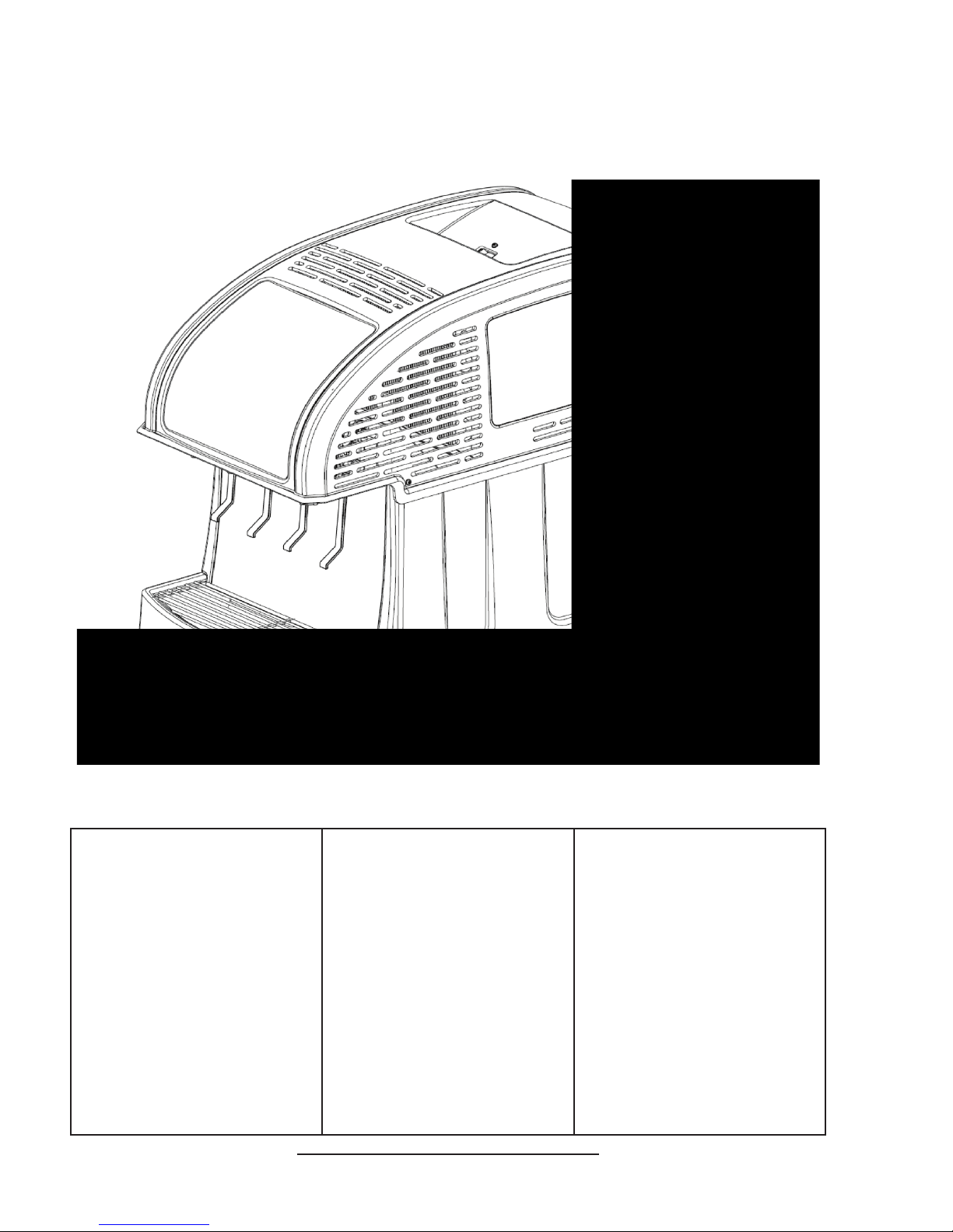
Spartan Dispenser
Operation Manual
PN: 28-0936
1600
Lancer Corp.
6655 Lancer Blvd.
San Antonio, Texas 78219
800-729-1500
Technical Support/Warranty: 800-729-1550
custserv@lancercorp.com
lancercorp.com
Manual PN: 28-0936
NOVEMBER 2013
FOR QUALIFIED INSTALLER ONLY
“Lancer” is the registered trademark of Lancer © 2014 by Lancer, all rights reserved.
Page 2

ABOUT THIS MANUAL
This booklet is an integral and essential part of the product and should be handed over to the operator after the
installation and preserved for any further consultation that may be necessary. Please read carefully the guidelines and
warnings contained herein as they are intended to provide the user with essential information for the continued safe
use and maintenance of the product. In addition, it provides GUIDANCE ONLY to the user on the correct services and
site location of the unit.
The installation and relocation, if necessary, of this product must be carried out by qualied personnel with up-to-date
safety and hygiene knowledge and practical experience, in accordance with current regulations.
TABLE OF CONTENTS
SPECIFICATIONS................................................................................................................................4
PRE-INSTALLATION CHECKLIST......................................................................................................5
WARNINGS/CAUTIONS...................................................................................................................6-9
1. INSTALLATION............................................................................................................................10
1.1 UNPACKING........................................................................................................................10
1.2 UNPACKING INSTALLATION KITS....................................................................................10
1.3 SELECTING A COUNTER LOCATION...............................................................................10
1.4 LEVELING THE DISPENSER.............................................................................................10
1.5 FILLING THE UNIT WITH W ATER......................................................................................10
1.6 CONNECTING TO ELECTRICAL POWER.........................................................................11
1.7 CONNECTING TO WATER SUPPLY..................................................................................11
1.8 CONNECTING TO CO2 SUPPLY.......................................................................................12
1.9 CONNECTING TO BAG-IN-BOX (BIB) SYRUP SUPPLY TO
REMOTE SYRUP PUMPS..................................................................................................12
1.10 PURGING THE CARBONATION SYSTEM........................................................................12
1.1 1 PURGING THE WATER AND SYRUP SYSTEMS..............................................................12
1.12 ADJUSTING WATER FLOW (LEV®)..................................................................................13
1.13 ADJUSTING WATER TO SYRUP (RATIO) BRIX (LEV®)..................................................13
1.14 SETTING 3-WAY ADJSTABLE BACK BLOCKS FOR PLAIN OR
CARBONATED WATER......................................................................................................14
2. SCHEDULED MAINTENANCE....................................................................................................14
2.1 AS NEEDED........................................................................................................................14
2.2 DAILY...................................................................................................................................14
2.3 WEEKLY..............................................................................................................................14
2.4 MONTHLY............................................................................................................................15
2.5 EVERY SIX MONTHS.........................................................................................................15
2.6 YEARLY...............................................................................................................................15
3. DISPENSER CLEANING AND SANITIZING..............................................................................15
3.1 GENERAL INFORMATION.................................................................................................15
3.2 CLEANING AND SANITIZING SOLUTIONS.......................................................................15
3.3 AMBIENT PROCESS..........................................................................................................16
3.4 NOZZLE CLEANING...........................................................................................................16
4. TROUBLESHOOTING............................................................................................................16-24
5. DISPENSER DISPOSAL.............................................................................................................24
6. TROUBLE SHOOTING THE LANCER ELECTRONIC ICE BANK CONTROL (EIBC)..............25
6.1 CHECKING FOR NORMAL PCB OPERATION..................................................................25
2
Page 3

7. ILLUSTRATIONS, PARTS LISTINGS, AND WIRING DIAGRAMS............................................26
7.1 MAIN UNIT ASSEMBLY .......................................................................................................26
7.2 PUMP ASSEMBLY..............................................................................................................27
7.3 REFRIGERATION DECK ASSEMBL Y................................................................................28
7.4 ELECTRICAL BOX ASSEMBLY..........................................................................................29
7.5 CARBONATOR ASSEMBL Y ................................................................................................30
7.6 REFRIGERATION DECK WIRING DIAGRAM....................................................................31
7.7 UNIT WIRING DIAGRAM....................................................................................................32
3
Page 4
SPARTAN SPECIFICATIONS
DIMENSIONS
Width: 15.7 in (399 mm)
Depth: 28.1 in (711.2 mm)
Height: 21.6 in (549 mm)
SPACE REQUIRED
Width: 4 in (101.6 mm)
Depth: 4 in (101.6 mm)
Back: 4 in (101.6 mm)
Top: 8 in (203.2 mm)
ELECTRICAL
115VAC/60Hz/4.3AMPs
208,203VAC/60Hz/2.0AMPs
220-240VAC/50Hz/2.6AMPs
This unit emits a sound pressure level below 70 dB
WEIGHT
Shipping: 110 lbs (49.9 kg)
Empty: 82 lbs (37.2 kg)
Operating: 127 lbs (57.5 kg)
ICE
Capacity: 8 - 11 lbs (3.6 - 5.0 kg)
FITTINGS
Water for carbonator inlet:
1/4” barb
Plain water inlet: 1/4” barb
Brand syrup inlets: 1/4” barb
CO2 inlet: 1/4” barb
4
PLAIN WATER SUPPLY
Min owing pressure: 75 PSIG
(5.28 kg/cm2, 0.516 MPA)
CARBONATOR WATER SUPPLY
Min owing pressure: 25 PSIG
(1.76 kg/cm2, 0.172 MPA)
Max static pressure: 50 PSIG
(3.52 kg/cm2, 0.345 MPA)
CARBON DIOXIDE (CO2)
Min pressure: 70 PSIG
(4.92 kg/cm2, 0.483 MPA)
Max pressure: 80 PSIG
(5.62 kg/cm2, 0.552 MPA)
Page 5
PRE-INSTALLATION CHECKLIST
BEFORE GETTING STARTED
Each unit is tested under operating conditions and is thoroughly inspected before
shipment. At the time of shipment, the carrier accepts responsibility for the unit. Upon
receiving the unit, carefully inspect the carton for visible damage. If damage exists, have
the carrier note the damage on the freight bill and le a claim with carrier. Responsibility for
damage to the dispenser lies with the carrier.
TOOLS REQUIRED
Oetiker Pliers Slotted Screwdriver
Tubing Cutters Phillips Screwdriver
Wrench Cordless Drill
POST MIX ACCESSORIES
CO2 Regulator Set CO2 Supply
Beverage Tubing Oetiker Clamps/Fittings
Water Booster Water Regulator
Precision Cutters (if removing/replacing carbonator tank)
BIB SYSTEM
BIB Rack BIB Regulator Set
BIB Syrup Boxes
BIB Connectors - ensure you have the correct connectors for syrup lineup.
CONSIDER LOCATION OF THE FOLLOWING PRIOR TO INSTALL
Water supply lines Drain
Is the countertop level? Heating and air conditioning ducts
Grounded electrical outlet.
Enough space to install the dispenser. Include space for a top-mounted ice machine, if necessary.
Does the top-mounted ice machine have a minimum clearance on all sides?
Located away from direct sunlight or overhead lighting.
Can the countertop support the weight of the dispenser? Be sure to include the weight of an ice
machine (if necessary) plus the weight of the ice.
This unit is not suitable for use in an area where a water jet could be used.
5
Page 6

! !
WARNING/ADVERTENCIA/AVERTISSEMENT
!
The dispenser is for indoor use only. This appliance is intended to be used in commercial applications such as
restaurants or similar. This unit is not a toy. Children should be supervised not to play with appliance. It should not be
used by children or inrm persons without supervision. This appliance is not intended for use by persons
(including children) with reduced physical, sensory or mental capabilities, or lack of experience and knowledge,
unless they have been given supervision or instruction concerning use of the appliance by a person responsible for
their safety. Cleaning and user maintenance shall not be performed by children without supervision. This appliance
can be used by children aged from 8 years and above and persons with reduced physical, sensory or mental
capabilities or lack of experience and knowledge if they have been given supervision or instruction concerning use of
the appliance in a safe way and understand the hazards involved. This unit is not designed to dispense dairy
products. The min/max ambient operating temperature for the dispenser is 40°F to 75°F (4°C to 24°C). Do not
operate unit below minimum ambient operation conditions. Should freezing occur, cease operation of the unit and
contact authorized service technician. Service, cleaning and sanitizing should be accomplished only by trained
personnel. Applicable safety precautions must be observed. Instruction warnings on the product being used must be
followed.
! El dispensador sólo debe usarse en interiores. Este aparato está diseñado para ser utilizado en aplicaciones
comerciales tales como restaurantes o similar. Esta unidad no es un juguete. Los niños deben ser supervisados para
no jugar con aparato. No la deben usar niños ni personas discapacitadas sin supervisión. Esta unidad no está
destinada al uso por parte de personas (incluso niños) con capacidad física, sensorial o mental reducida, o sin
experiencia y conocimientos sucientes, a menos que una persona responsable de su seguridad les haya dado
supervisión o capacitación en el uso de la unidad. Limpieza y mantenimiento de usuario no deberá ser realizada por
los niños sin supervisión. Este aparato puede ser utilizado por niños de 8 años o más y las personas con
capacidades físicas, sensoriales o mentales, o por falta de experiencia y conocimientos que hayan recibido
supervisión o instrucciones relativas al uso del aparato de una manera segura y comprenda los peligros
involucrados. Esta unidad no ha sido diseñada para suministrar productos lácteos. La temperatura ambiente
operativa mínima / máxima para el dispensador es de 40°F a 75°F (4°C a 24°C). No opere la unidad debajo de las
condiciones de funcionamiento ambientales mínimos. En caso de congelación se produce, cesar la operación de la
unidad y el contacto técnico de servicio autorizado. Servicio de limpieza y desinfección deben llevarse a cabo
solamente por personal capacitado. Es necesario tomar medidas de seguridad aplicables. Advertencias de las
instrucciones sobre el producto utilizado se deben seguir.
! Le distributeur est destiné à un usage à l’intérieur seulement. Cet appareil est conçu pour être utilisé dans des
applications commerciales comme les restaurants ou similaire. Cet appareil n’est pas un jouet. Les enfants doivent
être surveillés an de ne pas jouer avec l’appareil. Il ne devrait pas être utilisé par des enfants ou des personnes
inrmes sans surveillance. Cet appareil n’est pas destiné à un usage par des personnes (y compris les enfants)
ayant des capacités physiques, sensorielles ou mentales réduites, ou manquant d’expérience et de connaissances,
à moins qu’elles obtiennent de la surveillance ou des instructions au sujet de l’utilisation de l’appareil de la part
d’une personne chargée de leur sécurité. Nettoyage et entretien de l’utilisateur ne doivent pas être effectués par
des enfants sans surveillance. Cet appareil peut être utilisé par des enfants âgés de 8 ans et plus et les personnes
ayant des capacités ou le manque d’expérience et de connaissances physiques, sensorielles ou mentales réduites
si elles sont sans surveillance ou instruction concernant l’utilisation de l’appareil en toute sécurité et de comprendre
les risques impliqués. Cet appareil n’est pas conçu pour distribuer des produits laitiers. La température de service
ambiante minimum/maximum pour le distributeur est de 40°F à 75°F (4°C à 24°C). Ne pas utiliser l’appareil dans des
conditions de performance environnementale minimale. En cas de gel, cesser l’exploitation de l’unité et contactez un
technicien agréé. Nettoyage et désinfection doivent être effectuées uniquement par du personnel qualié. Vous devez
prendre des mesures de sécurité. Avertissements instructions sur le produit utilisé doivent être respectées.
6
Page 7
DISPENSER INSTALLATION HIGHLIGHTS
!
This unit has been factory sanitized per Lancer specications.
Listed below are six critical elements which will aid in a successful installation.
1. Fill water bath until water overows from tank overow tube.
2. The carbonator pump motor must be disconnected from the power supply (see Section 1.7) prior to connection to
water supply for initial build up of ice bank. Failure to do so will result in automatic shut off of carbonator (see item
6 below) or damage to the pump.
3. If this dispenser is installed in an area that is susceptible to ±10% variation of the nominal line voltage, consider
installing a surge protector or similar protection device.
4. There is a ve (5) minute delay which prevents the compressor and condenser fan from starting until the delay
has lapsed. If electrical current is interrupted, there is always a ve (5) minute delay before the compressor starts.
5. Supply Water Pressure: Minimum - 25 PSI (0.172 MPA); Maximum - 50 PSI (0.345 MPA); If pressure is over 50
PSIG (0.345 MPA), a water pressure regulator must be used.
6. On units with the built in water regulator, the regulator must be removed if inlet water pressure is less than 25
PSIG. (0.172 MPA)
!
PUNTOS IMPORTANTES EN LA UNIDAD DISPENSADORA
!
Esta unidad ha sido saneada en fabrica por las especicaciones de Lancer.
A continuacion se relacionan 6 puntos importantes para una connecta instalacion.
1. Llene el bano-Maria hasta que el agua se desborde sobre el tubo que controla la derrama del tanque.
2. El motor de la bomba del carbonatador debe desconectarse electricamente (Ver Manual - Seccion 1.7) antes
de conectar el suministro de agua para la formacion inicial del banco de hielo. De no hacerse esto resultaria en
un bloqueo automatico del carbonatador (ver abajo el punto 6) o en danos a la bomba.
3. Si la unidad va a ser instalada en un area en la que puedan darse variaciones de voltage de + 6 - 10% de su
valor nominal, se debe considerar la conveniencia de instalar un estabilizador de corriente o sistema de
proteccion similar.
4. Hay una demora de 5 minutos que evita que el compresor y el abanico del condensador arranquen hasta pasado
ese tiempo. Si hay algun corte en la corriente electrica siempre se producira esa demora de 5 minutos antes de
arrancar el compresor.
5. Presión de suministro del agua de red: Minimo 25 PSI (0.172 MPA); Maximo 50 PSI (0.345 MPA). En unidades
sin regulador de presión incorporado, si la presión del agua es superior a 50 PSIG (0.345 MPA) se debe usar un
regulador de presión.
6. En unidades con regulador de presión incorporado, el regulador debe der eliminado cuando la presión de entrada
de agua sea inferior a 25 PSIG (0.172 MPA).
REGLES DE SECURITE POUR L’NSTALLATION DU DISTRIBUTEUR DE SODAS
!
!
!
La proprètè da cet ensamable est assurè à I’usine sulvant les spècications èmis par Lancer .
Il est essentiel de respecter les 6 points suivants pour l’installation de l’appareil:
1. Remplir le bain-Maire jusqu’a ce que l’eau dèborde par le tuyau de trop-plein du rèservoir.
2. Le moteur de la pompe du carbonateur doit etre dèbranchè de l’alimentation èlectrique (Voir le manuel,
Section 1.7) avant l’arrivèe de l’eau pour la formation initiale de la glace. Oublier ou nègliger cette opèration
provoquera l’arret automatique du carbonateur (voir le point 6 cidessous) ou causera des dommages à la pompe.
3. Si le distributeur es installè dans une zone ou la tension èlectrique nominale est susceptible de variations de (+)
10%, il est conseillè d’installer un appaeil de protection contre les sautes de courant.
4. Un d’lai de 5 minutes empeche le compresseur et la ventilation du condesateur de se mettre en marche avant
que ce lees de temps ne se soit ècoulè. Lorsque le courant èlectrique es interrompu, il y a toujours un dèlai de 5
minutes avant que le presseur ne se mette en.
5. Pression de l’eau: Minimum 25 PSI (0.172 MPA); Maximo 50 PSI (0.345 MPA). Sur les unitès qui n’ont pas de
règulateur de pression d’eau incorprè, si la pression d’H2O est supèrieure à 50 PSIG (0.345 MPA), un règulateur
de pression d’eau doit etre utilsisè.
6. Sur les unitès avec règulateur d’eau incorporè, le règulateur doit etre enlevè si la pression d’arrivve est inferièure
à 25 PSIG (0.172 MPA)
7
Page 8
ELECTRICAL WARNING/ADVERTENCIA ELÉCTRICA/
F F
F
Check the dispenser serial number plate for correct electrical requirements of unit. Do not plug into a wall
electrical outlet unless the current shown on the serial number plate agrees with local current available. Follow
all local electrical codes when making connections. Each dispenser must have a separate electrical circuit. Do not
use extension cords with this unit. Do not ‘gang’ together with other electrical devices on the same outlet. The
keyswitch does not disable the line voltage to the transformer primary. Always disconnect electrical power to the unit
to prevent personal injury before attempting any internal maintenance. The resettable breaker switch should not
be used as a substitute for unplugging the dispenser from the power source to service the unit. Only qualied
personnel should service internal components of electrical control housing. Make sure that all water lines are tight
and units are dry before making any electrical connections!
AVERTISSEMENT ÉLECTRIQUE
F Verique la placa con el número de serie del dispensador, donde encontrará los requisitos eléctricos correctos
de la unidad. No enchufe la unidad en un tomacorriente de pared a menos que la corriente indicada en la placa con
el número de serie concuerde con la corriente local disponible. Al hacer las conexiones, respete todos los códigos
eléctricos locales. Cada dispensador debe tener un circuito eléctrico independiente. No use extensiones con esta
unidad. No la conecte junto con otros dispositivos eléctricos al mismo tomacorriente. El interruptor de llave no corta
el voltaje de línea al transformador primario, disconecte siempre la alimentación eléctrica a la unidad para evitar
lesiones personales antes de tratar de realizar tareas de mantenimiento. El disyuntor de sobrecarga
reseteable no se debe usar como sustituto para desenchufar el dispensador de la fuente de alimentación para
realizar tareas de servicio de la unidad. El servicio de los componentes internos de la caja de control eléctrico debe
conarse exclusivamente a personal calicado. Asegúrese de que todas las líneas de agua estén ajustadas y las
unidades estén secas antes de hacer conexiones eléctricas.
F Examinez la plaque de numéro de série du distributeur pour connaître les bonnes exigences en matière
d’électricité pour l’appareil. Ne le branchez pas à une prise électrique murale à moins que le courant indiqué sur la
plaque de numéro de série corresponde au courant local disponible. Respectez tous les codes électriques locaux
lorsque vous faites des connexions. Chaque distributrice doit avoir un circuit électrique séparé. N’utilisez pas
de cordons prolongateurs avec cet appareil. Ne pas le brancher avec d’autres appareils électriques sur la même
prise. L’interrupteur à clé ne coupe pas la tension secteur au transformateur primaire. Débranchez toujours le courant
électrique à l’appareil, an de prévenir des blessures, avant de faire un entretien interne quelconque. Le disjoncteur
réarmable ne devrait pas être utilisé au lieu de débrancher le distributeur de la source d’alimentation en électricité
pour faire de l’entretien/une réparation de l’appareil. Seul le personnel qualié devrait faire l’entretien/la réparation
des composants internes dans le logement des commandes électriques. Assurez-vous que toutes les conduites
d’eau sont étanches et que les appareils sont secs avant de faire des connexions électriques!
CO2/CARBON DIOXIDE /El ANHÍDRIDO CARBÓNICO/
5 5
5
Carbon Dioxide (CO2) is a colorless, noncombustible gas with a light pungent odor. High percentages of CO2 may
displace oxygen in the blood. Prolonged exposure to CO2 can be harmful. Personnel exposed to high concentrations
of CO2 gas will experience tremors which are followed by a loss of consciousness and suffocation. If a CO2 gas leak
is suspected, immediately ventilate the contaminated area before attempting to repair the leak. Strict attention must
be observed in the prevention of CO2 gas leaks in the entire CO2 and soft drink system.
5 El anhídrido carbónico (CO2) es un gas incoloro, no combustible, con un olor pungente ligero. Altos porcentajes
de CO2 en la sangre pueden desplazar el oxígeno en la sangre. La exposición prolongada al CO2 puede ser nociva.
El personal expuesto a concentraciones altas de CO2 sufre temblores seguidos de la pérdida de la consciencia y
sofocación. Si se sospecha que existe una pérdida de CO2, ventile el área contaminada antes de tratar de reparar
la pérdida. Hay que prestar suma atención para evitar pérdidas de CO2 en todo el sistema de CO2 y de bebidas
gaseosas.
5 Le dioxyde de carbone (CO2) est plus lourd que l’air et déplace l'oxygène. Le CO2 est un gaz incolore et
incombustible, ayant une odeur un peu âcre. Des concentrations fortes de CO2 peuvent déplacer l'oxygène dans le
sang. Une exposition prolongée au CO2 peut être nocive. Le personnel exposé à de fortes concentrations de CO2
gazeux éprouvera des tremblements, suivis rapidement d'une perte de conscience et de suffocation. On doit faire très
attention de prévenir les fuites de CO2 gazeux dans le système entier de CO2 et de boisson gazeuse. Si on suspecte
qu'il y a une fuite de CO2 gazeux, aérez le secteur contaminé immédiatement avant d'essayer de réparer la fuite.
DIOXYDE DE CARBONE
8
Page 9

AUTOMA TIC AGITATION/AGITACIÓN AUTOMÁTICA/
! Units are equipped with an automatic agitation system and will activate unexpectedly. Do not place hands or
foreign objects in the water bath tank. Unplug the dispenser during servicing, cleaning, and sanitizing. To avoid
personal injury, do not attempt to lift the dispenser without assistance. For heavier dispensers, use a mechanical lift.
! Las unidades están equipadas con un sistema automático de agitación, por lo que se pueden activar
repentinamente. No ponga las manos ni objetos extraños en el compartimiento donde se guarda el hielo. Durante el
servicio, la limpieza y la esterilización, desenchufe el dispensador. Para evitar lesiones personales, no trate de
levantar el dispensador sin ayuda. Para los dispensadores más pesados, use un elevador mecánico.
! Les appareils sont équipés d’un système d’agitation automatique qui s’activera de manière inattendue. Ne mettez
pas les mains ou des corps étrangers dans le compartiment d’entreposage de glace. Débranchez le distributeur
pendant l’entretien/la réparation, le nettoyage et l’aseptisation. Pour éviter des blessures, n’essayez pas de soulever
le distributeur sans aide. Pour les distributeurs plus lourds, utilisez un chariot élévateur.
! !
WATER NOTICE/AGUA AVISO/ PRÉAVIS DE L’EAU
!
Provide an adequate potable water supply. Water pipe connections and xtures directly connected to a potable
water supply must be sized, installed, and maintained according to federal, state, and local laws. The water supply line must be at least a 3/8 inches (9.525 mm) pipe with a minimum of 25 PSI (0.172 MPA) line pressure, but not
exceeding a maximum of 50 PSI (0.345 MPA). Water pressure exceeding 50 PSI (0.345 MPA) must be reduced to 50
PSI (0.345 MPA). Use a lter in the water line to avoid equipment damage and beverage off-taste. Check the water
lter periodically, as required by local conditions. The water supply must be protected by means of an air gap, a
backow prevention device (located upstream of the CO2 injection system) or another approved method to comply
with NSF standards. A leaking inlet water check valve will allow carbonated water to ow back through the pump
when it is shut off and contaminate the water supply. Ensure the backow prevention device complies with ASSE and
local standards. It is the responsibility of the installer to ensure compliance.
! Proporcione un suministro adecuado de agua potable. La línea de suministro de agua debe ser de una tubería de
por lo menos 3/8 pulgadas (9.525 mm) con una presión de línea mínima de 25 PSI (0.172 MPA) , pero sin superar
el máximo de 50 PSI (0.345 MPA). La presión de agua que supere los 50 PSI se debe reducir a 50 PSI (0.345 MPA)
con un regulador de presión. Use un ltro en la línea de agua para evitar daños al equipo y cierto sabor raro en las
bebidas. Verique periódicamente el ltro de agua de acuerdo con las condiciones imperantes. El suministro de
agua debe estar protegido por una separación de aire, un dispositivo de prevención del contraujo (situado antes del
sistema de inyección de CO2) u otro método aprobado para cumplir las normas NSF. Si la válvula de retención de
entrada de agua tuviera pérdidas, permitiría el contraujo del agua carbonatada a través de la bomba cuando se la
detiene y contaminaría el suministro de agua. Asegúrese de que el dispositivo de prevención del contraujo cumpla
con las normas locales y de ASSE. Es responsabilidad del instalador cumplir con estos requisitos.
! Fournissez une alimentation en eau potable adéquate. Les connexions et les dispositifs de conduite d’eau
con- nectés directement à une alimentation en eau potable doivent être calibrés, installés et maintenus selon les lois
fédérales, provinciales et locales. La conduite d’alimentation en eau doit être un tuyau d’au moins 3/8 pouces (9.525
millimètres) avec une pression de ligne minimum de 25 LPC (0.172 MPA) , mais ne doit pas dépasser un maximum
de 50 LPC (0.345 MPA). Une pression d’eau de plus de 50 LPC (0.345 MPA) doit être réduite à 550 LPC (0.345
MPA) avec le régu- lateur de pression fourni. Utilisez un ltre dans la conduite d’eau pour éviter des dommages à
l’équipement et un goût des boissons qui n’est pas juste. Vériez le ltre à eau périodiquement, selon les exigences
des conditions locales. L’alimentation en eau doit être protégée au moyen d’un intervalle d’air, un disconnecteur
hydraulique (situé en amont du système d’injection de CO2) ou une autre méthode approuvée pour se conformer
aux normes de la NSF. Un clapet antiretour pour l’eau entrante qui fuie permettra à l’eau gazeuse de repasser par
la pompe quand elle est fermée et de contaminer l’alimentation en eau. Assurez-vous que le disjoncteur hydraulique
soit conforme aux normes de l’ASSE et locales. L’installateur est responsable d’assurer la conformité.
9
Page 10

1. INSTALLATION
1.1 UNPACKING
A. Cut band and remove.
B. Remove accessory kit and loose parts.
C. Remove top board, corner inserts, and lift outer carton to remove, if included.
D. Inspect unit for concealed damage. If evident, notify delivering carrier and le a claim against
same.
E. Remove plywood shipping base from unit by moving unit so that one side is off the counter top
or table allowing access to screws on the bottom of the plywood shipping base.
NOTE: If unit is to be transported, it is advisable to leave the unit secured to the plywood base.
F. If leg kit has been provided, assemble legs to unit by tilting unit. DO NOT LAY UNIT ON ITS
SIDE OR BACK.
1.2 UNPACKING INSTALLATION KITS
A. Inspect kits for concealed damage and if evident, notify delivering carrier and le a claim
against same.
B. Each kit contains a list of the parts and a drawing showing the proper assembly of the parts.
1.3 SELECTING A COUNTER LOCATION
A. Select a location close to a properly grounded electrical outlet and water supply that meet the
requirements as shown in the SPECIFICATIONS section.
WARNING FAILURE TO MAINTAIN SPECIFIED CLEARANCE WILL CAUSE THE COMPRESSOR TO OVERHEAT
AND WILL RESULT IN COMPRESSOR FAILURE.
ADVERTENCIA SI NO DEJA EL ESPACIO LIBRE ESPECIFICADO EL COMPRESOR PUEDE RECALENTAR Y
FALLAR.
!
AVERTISSEMENT LE FAIT DE NE PAS MAINTENIR LE DÉGAGEMENT SPÉCIFIÉ FERA SURCHAUFFER LE
COMPRESSEUR ET AURA COMME CONSÉQUENCE UNE DÉFAILLANCE DU COMPRESSEUR.
B. Condenser air is drawn in from the front and side vents located on the bonnet, and discharged
out the rear of the bonnet. A minimum of eight (8) inches (203 mm) clearance must be main
tained over the top of the unit and a minimum 4 inches behind the unit to provide for proper air
ow and air circulation.
1.4 LEVELING THE DISPENSER
In order to facilitate proper dispenser drainage and carbonation, ensure that the dispenser is level,
front to back and side to side. Place a level on the top of the rear edge of the dispenser. The bubble
must settle between the level lines. Repeat this procedure for the remaining three sides. Level
unit if necessary. For optimum performance place the unit at a 0 degree tilt. The maximum tilt is 5
degrees.
1.5 FILLING UNIT WITH WATER
CAUTION THE WATER BATH COMPARTMENT MUST BE FILLED WITH WATER BEFORE PLUGGING IN THE UNIT,
OTHERWISE THE COMPRESSOR DECK AND CONDENSOR FAN MAY NOT OPERATE PROPERLY
PRECAUCIÓN EL COMPARTIMIENTO DE BAÑO DE AGUA DEBA ESTAR LLENO DE AGUA ANTES DE ENCHUFAR
LA UNIDAD PUES, DE LO CONTARIO, LA PLATAFORMA DEL COMPRESOR Y EL VENTILADOR DEL
CONDENSADOR NO FUNCIONARÍAN CORRECTAMENTE.
!
ATTENTION LE COMPARTIMENT DE BAIN-MARIE DOIT ÊTRE REMPLI AVEC DE L’EAU AVANT DE BRANCHER
L’APPAREIL, SINON LA PLATEFORME DU COMPRESSEUR ET LE VENTILATEUR DU CON- DENSATEUR PEUVENT
NE PAS FONCTIONNER CORRECTEMENT.
A. Remove splash plate and drip tray. Assemble drain tube on drip tray drain elbow.
B. Remove the bonnet from the unit by removing the two side screws, top screw, and lifting
upward.
C. Locate the opening in the compressor deck. A yellow cap will identify opening. Remove the cap.
D. Using a funnel or tube, ll the water bath compartment, with water until it ows out of the over
ow tube into the drip tray.
10
Page 11

1.6 CONNECTING TO ELECTRICAL POWER
NOTE: Adhere to the ELECTRICAL Warnings/Cautions, Page 4.
GROUNDING WARNING THE DISPENSER MUST BE PROPERLY ELECTRICALLY GROUNDED TO AVOID
SERIOUS INJURY OR FATAL ELECTRICAL SHOCK. THE POWER CORD HAS A THREE-PRONG GROUNDED
PLUG. IF A THREE-HOLE GROUNDED ELECTRICAL OUTLET IS NOT AVAILABLE, USE AN APPROVED METHOD TO
GROUND THE UNIT. FOLLOW ALL LOCAL ELECTRICAL CODES WHEN MAKING CONNECTIONS. EACH
DISPENSER MUST HAVE A SEPARATE ELECTRICAL CIRCUIT. DO NOT USE EXTENSION CORDS. DO NOT
CONNECT MULTIPLE ELECTRICAL DEVICES ON THE SAME OUTLET.
ADVERTENCIA, PUESTA A TIERRA ES NECESARIO PONER A TIERRA ELÉCTRICAMENTE EL
DISPENSADOR PARA EVITAR LESIONES GRAVES E INCLUSO ELECTROCHOQUES FATALES. EL CABLE DE
ALIMENTACIÓN TIENE UN ENCHUFE PUESTO A TIERRA DE 3 CLAVIJAS. SI NO SE DISPONE DE UN TOMA
ELÉCTRICO CONECTADO A TIERRA DE TRES AGUJEROS, USE UN MÉTODO APROBADO PARA PONER A TIERRA
LA UNIDAD. AL HACER LAS CONEXIONES, RESPETE TODOS LOS CÓDIGOS ELÉCTRICOS LOCALES. CADA
F
DISPENSADOR DEBE TENER UN CIRCUITO ELÉCTRICO INDEPENDIENTE. NO USE CABLES DE EXTENSIÓN. NO
CONECTE VARIOS DISPOSITIVOS ELÉCTRICOS AL MISMO TOMACORRIENTE.
EXIGENCES DE MISE À LA TERRE LA DISTRIBUTRICE DOIT ÊTRE MISE À LA TERRE ÉLECTRIQUEMENT
CORRECTEMENT POUR ÉVITER DES BLESSURES GRAVES OU UNE DÉCHARGE ÉLECTRIQUE MORTELLE. LE
CORDON D’ALIMENTATION A UNE FICHE À TROIS BRANCHES MISE À LA TERRE. SI AUCUNE PRISE DE
COURANT ÉLECTRIQUE À TROIS TROUS N’EST DISPONIBLE, UTILISEZ UNE MÉTHODE APPROUVÉE POUR
METTRE L’UNITÉ À LA TERRE. RESPECTEZ TOUS LES CODES ÉLECTRIQUES LOCAUX LORSQUE VOUS FAITES
DES CONNEXIONS. CHAQUE DISTRIBUTRICE DOIT AVOIR UN CIRCUIT ÉLECTRIQUE SÉPARÉ. N’UTILISEZ PAS
DE CORDONS PROLONGATEURS. NE BRANCHEZ PAS PLUSIEURS APPAREILS ÉLECTRIQUES À LA MÊME PRISE
DE COURANT.
CAUTION FAILURE TO DISCONNECT THE MOTOR POWER SUPPLY WILL DAMAGE THE CARBONATOR
MOTOR, THE PUMP AND VOID THE WARRANTY.
PRECAUCIÓN SI NO DESCONECTA LA ALIMENTACIÓN ELÉCTRICA DEL MOTOR PODRÍAN DAÑARSE LA BOMBA
Y EL MOTOR DEL CARBONATADO Y ANULAR LA GARANTÍA.
F
ATTENTION LE FAIT DE NE PAS MAINTENIR LE DÉGAGEMENT SPÉCIFIÉ FERA SURCHAUFFER LE
COMPRESSEUR ET AURA COMME CONSÉQUENCE UNE DÉFAILLANCE DU COMPRESSEUR.
A. If the unit is equipped with a built-in carbonator, disconnect the power supply to the carbonator
motor by disconnecting the designated connector located near the top of the electrical control
box on the refrigeration deck.
B. Check the dispenser serial number plate for correct electrical requirements of unit. Do not plug
into wall electrical outlet unless the current shown on the serial number plate agrees with
local current available.
C. Route the power supply cord to a grounded electrical outlet of the proper voltage and amperage
rating, and plug in the unit. This will turn on the refrigeration system and allow it to start cooling
while completing the rest of the installation. The agitator motor will start immediately, but the
compressor and fan motor will not start until the ve (5) minute delay has elapsed.
1.7 CONNECTING TO WATER SUPPLY
NOTE: Adhere to the WATER SUPPLY Warnings/Cautions, Page 6.
A. Using appropriate tubing and ttings, connect tubing assembly to water source. Do not reuse
beverage tubing. Installer should provide new beverage tubing that meets the IEC Standard 61770.
Do not reuse beverage tubing. Lancer beverage tubing kits are available for purchase. Contact your
Sales Representative or Lancer Customer Service for more information.
DO NOT CONNECT TO DISPENSER AT THIS TIME.
B. Flush water supply line thoroughly.
C. Route tubing through a hole in the counter or underneath the dispenser. All water, CO2, and
syrup inlets are located behind the rear guard on the back of the unit.
D. Leave 12 inches (305 mm) of extra tubing length below the counter for servicing and moving the
dispenser.
E. Turn on water supply and check for leaks.
11
Page 12

1.8 CONNECTING THE CO2 SUPPLY
A. Connect high pressure CO2 regulator assembly to CO2 cylinder or bulk system. Use a new CO2
tank washer if regulator does not have built-in o-ring seal.
B. Place CO2 cylinder in service location under counter, etc., and secure it with a safety chain.
C. Install secondary CO2 regulator if the bulk system is utilized.
D. Route gas line through hole in counter. Connect CO2 to designated inlet behind the dispenser.
E. Leave 12 inches (305 mm) of extra tubing length below the counter for servicing and moving the
dispenser.
WARNING DO NOT TURN ON THE CO2 SUPPLY AT THIS TIME.
ADVERTENCIA NO CONECTE TODAVÍA LA ALIMENTACIÓN DE CO2.
5
1.9 CONNECTING TO BAG-IN-BOX (BIB) SYRUP SUPPLY TO REMOTE SYRUP PUMPS
1.10 PURGING THE CARBONATION SYSTEM
A. Turn on water source. Lift the black lever on the top of the carbonator tank relief valve until
B. Reconnect the power supply to the carbonator pump.
C. Back off on the CO2 regulator pressure adjusting screw all the way. Open the CO2 cylinder
D. Press and hold each valve lever until water is owing steadily from each valve.
E. Check all of the unit’s water, syrup, and CO2 connections for leaks and repair if necessary.
NOTE: Tank Method Only - to check for CO2 leaks, close the valve on the CO2 cylinder and
F. Assemble the unit’s bonnet, splash plate, and rear guard.
NOTE: Ensure a minimum of 5 gallons of water is ushed through each valve prior to use.
1.11 PURGING THE WATER AND SYRUP SYSTEMS
A. Set the adjustable back blocks to deliver plain water
B. Open a dispensing valve until water and syrup are owing steadily from the valve.
C. Repeat procedure “A” for each valve.
D. Check all of the unit’s syrup and water connections for leaks and repair if necessary.
E. Replace the unit’s bonnet, splash plate and cup rest
AVERTISSEMENT N’OUVREZ PAS L’ALIMENTATION EN CO2 À CE MOMENT.
A. To connect CO2 regulator assembly to the CO2 cylinder, see Section 1.9, Steps A - C.
B. Place the remote BIB syrup supply and pumps in a convenient location.
C. Attach the syrup supply tubes to the dispenser’s syrup inlet fittings using an Oetiker clamp for
each syrup flavor.
D. Route the syrup supply tubes to the remote syrup pumps.
E. Complete installation of the remote syrup pump system following the manufacturer’s
instructions.
water ows from the holes in the relief valve. Then release the relief valve.
handle slowly. Turn the CO2 pressure regulator up slowly to 75 PSIG (0.510 MPA).
observe if the pressure to the system drops with the cylinder valve closed for ve (5) minutes.
Open the cylinder valve after check.
12
Page 13

1.12 ADJUSTING WATER FLOW (LEV®)
FLOW CONTROL
WATER
SODA LEVER
(Optional)
CUP LEVER
NOZZLE
COVER
COVER SCREW
ID PANEL
(Shown in
open position)
NOZZLE
MANUFACTURE
SERIES NO.
Increase Decrease
FLOW CONTROL
SYRUP
Increase Decrease
A. The water ow must be adjusted to 1.25 oz/sec (37 ml/sec)
on all dispensing valves using the following procedures.
NOTE: Exceeding 2.0 oz/sec (74 ml/sec) may lead to gas-out.
B. The refridgeration unit should have been running for at least
one (1) hour before you attempt to brix the valves. The drink
temperature should be no higher than 40°F (4.4°C) when the
brix is set. This is best done after the unit has made
an ice bank.
C. Slide up ID panel until ow controls are exposed
(see Figure 1)
D. Remove nozzle by twisting counter clockwise and
pulling down.
E. Remove diffuser by pulling down.
F. Install Lancer (yellow) syrup separator (PN 54-0031)
in place of nozzle.
G. Activate dispensing valve to ll separator syrup tube.
H. Hold a Lancer brix cup under the syrup separator
and dispense water and syrup into cup for four (4)
seconds. Divide number of ounces (ml) of water
in cup by four (4) to determine water ow rate per
second
I. To obtain the proper ow, use a screwdriver to adjust
water ow control (see Figure 1).
J. Repeat process for each valve.
Typical Valve Adjustment, LEV®
Figure 1
1.13 ADJUSTING WATER TO SYRUP (RATIO) BRIX (LEV®)
A. Hold the Lancer brix cup under the syrup separator and activate valve. Check brix.
B. To obtain the proper brix, use screwdriver to adjust syrup ow control (see Figure 1).
C. Once proper ratio is obtained repeat to verify.
D. Remove syrup separator (PN 54-0031 installed in Section 1.13.F above).
E. Install diffuser and nozzle.
F. Slide down ID panel.
G. Repeat process for each valve.
13
Page 14

1.14 SETTING 3-WAY ADJSTABLE BACK BLOCKS FOR PLAIN OR CARBONATED WATER
3 - WAY BACK BLOCK
REAR VIEW
TOP VIEW
(SHUT-OFF ORIENTATION)
PLAIN WATER ON
CARB WATER ON
SY
PW
S
VALVE CLOSED
PN 06-2874
LEGEND:
SY = SYRUP LINE
S = SODA LINE
PW = PLAIN WATER LINE
A. The shut-off stem on the left side of the back block controls the ow of plain or carbonated
water. The stem has a straight side and a double curved side when looking down at the back
block. To set the adjustable back block to deliver plain water, turn the shut-off stem to where the
straight side of the stem is facing to the left. To set the back block to deliver carbonated water,
turn the shut-off stem to where the straight side faces to the right. When the shut-off stem is
at its midpoint, with the straight side facing forward, the ow of either plain or carbonated water
is shut-off.
B. Be sure the shut-off stem is fully turned to the desired position, or the ow of water will be
restricted.
Setting 3-Way Adjustable Back Blocks
2. SCHEDULED MAINTENANCE
CAUTION FOLLOWING SANITIZATION, RINSE WITH END-USE PRODUCT UNTIL THERE IS NO AFTERTASTE. DO
NOT USE A FRESH WATER RINSE. THIS IS A NSF REQUIREMENT. RESIDUAL SANITIZING SOLUTION LEFT IN THE
SYSTEM CREATES A HEALTH HAZARD.
PRECAUCIÓN DESPUÉS DE LA ESTERILIZACIÓN, ENJUAGUE CON EL PRODUCTO FINAL HASTA QUE
ELIMINAR EL SABOR QUE QUEDA. NO ENJUAGUE CON AGUA FRESCA. ÉSTA ES UNA EXIGENCIA DE NSF. SI
!
QUEDA SOLUCIÓN DE ESTERILIZACIÓN EN EL SISTEMA, GENERA UN PELIGRO PARA LA SALUD.
ATTENTION DÉFENSE DE RINCER L’OUTIL À L’EAU FRAICHE IMMÉDIATEMENT APRÈS UN TRAITEMENT
SEPTIQUE.EN CAS DE APRÈS-GOÛT, NE PURGER AVEC LE PRODUIT FINAL UNE EXIGENCE NSF.
2.1 AS NEEDED
Keep exterior surfaces of dispenser (include drip tray and cup rest) clean using a clean, damp cloth.
2.2 DAILY
A. Remove each nozzle and rinse well in warm water. DO NOT use soap or detergent. This will
cause foaming and off taste in nished product.
B. Remove the cup rest and wash in warm soapy water.
C. Pour warm soapy water into the drip tray and wipe with a clean cloth.
D. With a clean cloth and warm water, wipe off all of the unit’s exterior surfaces. DO NOT USE
ABRASIVE SOAPS OR STRONG DETERGENTS.
E. Replace the cup rest and nozzles.
2.3 WEEKLY
A. Taste each product for off tastes.
B. Remove cup rest and splash plate to view water level tube indicator. Replenish as required, and
replace the cup rest and splash plate.
Figure 2
14
Page 15

2.4 MONTHLY
A. Unplug the dispenser from power source.
B. Remove the bonnet and clean the dirt from the condenser using a soft brush.
C. Replace the bonnet and plug in the unit.
2.5 EVERY SIX MONTHS
A. Clean and sanitize the unit using the appropriate procedures outlined in Section 3 of this
manual.
2.6 YEARLY
A. Clean water bath interior, including evaporator coils and refrigeration components.
B. Clean the entire exterior of the unit.
3. DISPENSER CLEANING AND SANITIZATION
3.1 GENERAL INFORMATION
A. Lancer equipment (new or reconditioned) is shipped from the factory cleaned and sanitized
in accordance with NSF guidelines. The operator of the equipment must provide continuous
maintenance as required by this manual and/or state and local health department guidelines to
ensure proper operation and sanitation requirements are maintained.
NOTE: The cleaning procedures provided herein pertain to the Lancer equipment identied by
this manual. If other equipment is being cleaned, follow the guidelines established by the
manufacturer for that equipment.
B. Cleaning should be accomplished only by trained personnel. Sanitary gloves are to be used
during cleaning operations. Applicable safety precautions must be observed. Instruction
warnings on the product being used must be followed.
USE SANITARY GLOVES.
OBSERVE APPLICABLE SAFETY PRECAUTIONS.
x DO NOT USE A WATER JET TO CLEAN OR SANITIZE THE UNIT
x DO NOT DISCONNECT WATER LINES WHEN CLEANING AND SANITIZING SYRUP LINES, TO
AVOID CONTAMINATION.
x DO NOT USE STRONG BLEACHES OR DETERGENTS; THESE CAN DISCOLOR AND
CORRODE VARIOUS MATERIALS.
x DO NOT USE METAL SCRAPERS, SHARP OBJECTS, STEEL WOOL, SCOURING PADS,
ABRASIVES, OR SOLVENTS ON THE DISPENSER.
x DO NOT USE HOT WATER ABOVE 140º F (60º C). THIS CAN DAMAGE THE DISPENSER.
x DO NOT SPILL SANITIZING SOLUTION ON ANY CIRCUIT BOARDS. INSURE ALL SANITIZING
SOLUTION IS REMOVED FROM THE SYSTEM.
3.2 CLEANING AND SANITIZING SOLUTIONS
CLEANING SOLUTION: Mix a mild, non-abrasive detergent (e.g. Sodium Laureth Sulfate, dish
soap) with clean, potable water at a temperature of 90°F to 110°F (32°C to 43°C). The mixture
ratio is one ounce of cleaner to two gallons of water. Prepare a minimum of ve gallons of cleaning
solution. Do not use abrasive cleaners or solvents because they can cause permanent damage to
the unit. Ensure rinsing is thorough, using clean, potable water at a temperature of 90°F to 110°F.
Extended lengths of product lines may require additional cleaning solution.
SANITIZING SOLUTION: Prepare sanitizing solutions in accordance with the manufacturer’s
written recommendations and safety guidelines. The solution must provide 50 to 100 parts per
million (PPM) chlorine (e.g. Sodium Hypochlorite or bleach). A minimum of ve gallons of
sanitizing solution should be prepared. Any sanitizing solution may be used as long as it is prepared
in accordance with the manufacturer’s written recommendations and safety guidelines, and
provides 50 to 100 parts per million (PPM) chlorine.
15
Page 16

3.2 CLEANING AND SANITIZING SOLUTIONS (CONTINUED)
INTEGRITY OF THE PLASTIC FINISH: While caring for your Spartan, please note that there may
be some cleaners that may compromise the integrity of the plastic nish. Most common cleaners
such as Windex, Dawn, 409, etc. pose no threat to the plastic nish of the unit. However, certain
cleaners with high levels of acetic acid, ethylbenzene, isopropylamine, etc., at certain temperatures,
could cause aesthetic damage. Please refer to this webpage, http://www.vita.com.cy/index.php/
chemical-resistance-of-lldpe, to make sure that you are properly caring for your unit.
3.3 AMBIENT PROCESS
The ambient process is the most common method for cleaning and sanitizing dispenser equipment.
A. Prepare the Cleaning Solution,referred to in Section 3.2.
B. Fill lines at pump inlet with Cleaning Solution ( Section 2.2). The solution should be prepared in
accordance with the manufacturer’s recommendations. Make sure the lines are completely lled
and allow to stand for at least ten (10) minutes.
C. Flush the detergent solution from the lines with clean water.
D. Prepare the Sanitizing Solution, referred to in Section 3.2.
E. Fill the lines with Sanitizing Solution. Make sure that lines are completely lled and allow to
stand for ten (10) minutes.
F. Draw drinks to rell lines and ush solution from the dispenser.
G. Taste the beverage to verify that there is no off taste. If off-taste is found, ush the syrup
system again.
CAUTION FOLLOWING SANITIZATION, RINSE WITH END-USE PRODUCT UNTIL THERE IS NO AFTERTASTE. DO
NOT USE A FRESH WATER RINSE. THIS IS A NSF REQUIREMENT. RESIDUAL SANITIZING SOLUTION LEFT IN THE
SYSTEM CREATES A HEALTH HAZARD.
PRECAUCIÓN DESPUÉS DE LA ESTERILIZACIÓN, ENJUAGUE CON EL PRODUCTO FINAL HASTA QUE
ELIMINAR EL SABOR QUE QUEDA. NO ENJUAGUE CON AGUA FRESCA. ÉSTA ES UNA EXIGENCIA DE NSF. SI
!
3.4 NOZZLE CLEANING
A. Disconnect power so not to activate the valve while cleaning. Remove nozzle and diffuser. Wash
15 minutes.
B. Wearing sanitary gloves, remove, drain and air dry the nozzle and diffuser.
C. Wearing sanitary gloves, replace diffuser and twist nozzle into place.
D. Connect power.
4. TROUBLESHOOTING
4.1 Water leakage around nozzle. A. Damaged or improperly installed o-ring
4.2 Leakae between upper and lower
valve bodies.
QUEDA SOLUCIÓN DE ESTERILIZACIÓN EN EL SISTEMA, GENERA UN PELIGRO PARA LA SALUD.
ATTENTION DÉFENSE DE RINCER L’OUTIL À L’EAU FRAICHE IMMÉDIATEMENT APRÈS UN TRAITEMENT
SEPTIQUE.EN CAS DE APRÈS-GOÛT, NE PURGER AVEC LE PRODUIT FINAL UNE EXIGENCE NSF.
these parts in cleaning solution, then immerse them in a bath of sanitizing solution for
TROUBLE CAUSE REMEDY
A. if damaged, replace. If imporoperly
above diffuser.
A. Gap between upper and lower valve
bodies.
B. Worn or damaged paddle arm
assemblies.
installed, adjust.
A. Tighten all six (6) retaining screws.
B. Replace paddle arm assemblies.
C. Cracked valve bodies
4.3 Miscellanease leakage. A. Gap between parts.
B. Damaged or improperly installed
o-rings.
C. Replace Valve Body.
A. Tighten appropriate retaining screws
B. Replace or adjust appropriate o-rings
16
Page 17

TROUBLE CAUSE REMEDY
4.4 Insufcient water ow. A. Insufcient incoming supply water
pressure.
A. Verify incoming supply water pressure
is a minimum of 25 PSI (0.172 MPA).
B. Shutoff on mounting bloack not fully
open.
C. Foreign debris in water ow control.
D. Foreign debris in water pump strainer
4.5 Insufcient syrup ow. A. Insufcent CO
pressure to BIB pumps.
2
B. Out of CO2 .
C. Shutoff on mounting block not fully
open.
D. Foreign debris in syrup ow control.
E. Bad syrup pump.
4.6 Erratic ratio. A. Incoming water and/or syrup supply
not at minimum owing pressure.
B. Open shutoff fully.
C. Remove water ow control from upper
body and clean out any foreign material
to ensure smooth free spool movement.
D. Remove water pump strainer and
clean.
A. Adjust CO
pressure to 80 PSI (0.550
2
MPA) [minimum 70 PSI (0.480 MPA)] for
BIB pumps.
B. Replace CO
tank/rell.
2
C. Open shutoff fully.
D. Remove syrup ow control form upper
body and clean out any foreign material
to ensure smooth free spool movement.
E. Replace BIB pump.
A. Check pressure and adjust
B. Foreign debris in water and/or syrup
ow controls.
4.7 No product dispensed A. Water and syrup shutoffs on mounting
block not fully open.
B. The key switch on an electric valve is
in the OFF position.
C. Cup lever arm or ID panel actuator on
electric valve is not actuating the switch.
D. Electric current not reaching valve.
E. Improper or inadequate water or syrup
supply.
F. Transformer Failure
B. Remove ow controls from upper body
and clean out any foreign material to
ensure smooth free spool movement.
A. Open shutoff fully.
B. Turn key switch to ON position.
C. Repair
D. Check electric current supplied to
valve. If current is adequate, check
solenoid coil and switch, and replace if
necessary.
E. Remove valve from mounting block
and open shutoffs slightly and check
water and syrup ow. If no ow, check
dispenser for freeze-up or other problems
F. Reset transformer circuit breaker. If
breaker trips again check for pinched wire
harness at backblocks
G. Bad valve solenoid(s)
G. Replace Solenoid(s)
CONTINUED ON NEXT PAGE.....
17
Page 18

TROUBLE CAUSE REMEDY
4.8 Water only dispensed; no syrup; or
syrup only dispensed, no water
A. Water or syrup shutoff on mounting
block not fully open.
A. Open shutoff fully.
4.9 No water just syrup, (Ice bank grew to
water inlet line to carbonator tank.)
B. Improper or inadequate water or syrup
ow.
C. BIB supply too far from
dispenser.
D. CO2 pressure too low.
E. Stalled or inoperative BIB
pump
F. Kinked line.
A. Low water bath level.
B. Unit not level.
B. Remove valve from mounting block,
open shutoffs slightly and check water
and syrup ow. If no ow, check
dispenser for freeze-up or other
problems. Ensure BIB connection is
engaged.
C. Check that BIB supply is within six (6)
feet of the dispenser.
D. Check the CO2 pressure to the pump
manifold to ensure it is between 70
and 80 PSI.
E. Check CO2 pressure and/or replace
pump.
F. Remove kink or replace line.
A. Add water until it ows from overow
tube.
B. Level unit and add water.
C. Syrup in water bath.
D. Water cage is out of position.
E. Refrigerant leak.
F. Check water supply.
G. Carbonator timed out.
H. PCB malfunctioning.
4.10 Valve will not shut off. A. Cup lever may be sticking or binding.
B. Switch not actuating freely.
C. Solenoid armature not returning to
bottom position.
C. Melt ice bank. Remove all water. Rell.
Locate possible syrup leak area and
repair.
D. Reposition water cage.
E. Find leak and recharge unit. (If unit is
not frozen.)
F. Turn water ON and shut unit OFF,
G. Turn unit OFF then ON to reset
H. Refer to Section 6.
A. Correct or replace lever.
B. Check switch for free actuation.
C. Replace defective armature or spring.
18
Page 19

TROUBLE CAUSE REMEDY
4.11 Syrup only dispensed. No water, but
CO2 gas dispensed with syrup.
A. Improper water ow to dispenser.
A. Check for water ow to dispenser (see
4.4).
B. Carbonator pump motor has timed out.
C. Liquid level probe not connected
properly to PCB.
D. Faulty PCB assembly.
E. Faulty liquid level probe.
F. Water bath frozen.
G. Water line frozen.
4.12 Excessive foaming. A. Incoming water or syrup temperature
too high.
B. CO2 pressure too high.
B. Reset by turning the unit OFF and then
ON (by using the ON/OFF switch on top
of the unit or unplugging unit
momentarily).
C. Check connections of liquid level
probe to PCB assembly.
D. Replace PCB assembly.
E. Replace liquid level probe.
F. Thaw water bath and repair faulty
component. (See refrigeration related
symptoms.)
G. Refer to 4.14 listed below.
A. Correct prior to dispenser. Consider
larger dispenser or pre-cooler.
B. Adjust CO2 pressure downward, but
not less than 70 PSI.
4.13 Water continually overows from
water bath into drip tray.
4.14 Compressor starts and continues to
run until freeze and will not cut off.
C. Water ow rate too high.
D. Nozzle and diffuser not installed.
E. Nozzle and diffuser not clean.
F. Air in BIB lines.
G. Poor quality ice.
H. High beverage temperature.
A. Loose water connection(s).
B. Flare seal washer leaks.
C. Faulty water coil.
A. PCB malfunctioning or faulty ice bank
probe.
B. Ice bank probe positioned improperly.
C. Readjust and reset ratio. Refer to
Section 1.18.
D. Remove and reinstall properly.
E. Remove and clean.
F. Bleed air from BIB lines.
G. Check quality of ice used in drink.
H. Check refrigeration system.
A. Tighten water connections.
B. Replace are seal washer.
C. Replace water coil.
A. Refer to Section 6.
B. Check positioning of ice bank probe,
and replace if needed.
C. Ice bank probe shorted to ground.
19
C. Replace ice bank probe.
CONTINUED ON NEXT PAGE.....
Page 20

4.15
Warm drinks.
TROUBLE CAUSE REMEDY
A. Restricted airow.
A. Check clearances around sides, top,
and inlet of unit. Remove objects blocking
airow through grill.
4.16 Compressor does not start (no
hum), gas cooler fan does not run, and
no ice bank.
B. Dispenser connected to hot water
supply.
C. Refrigeration system not running.
D. Refrigerant leak.
E. Condenser fan motor not working.
F. Dirty condenser.
G. Dispenser capacity exceeded.
A. There is a ve (5) minute compressor
and condenser fan delay.
B. Ice bank probe not completely
submergered.
C. Circuit breaker or fuse tripped.
D. Inadeequate Voltage
B. Switch to cold water supply.
C. Refer to 5.16 - 5.20.correct relay will
cause compressor failure.
D. Repair and recharge.
E. Replace condenser fan motor.
F. Clean condenser.
G. Add pre-cooler or replace with larger
dispenser.
A. Allow for ve (5) minute delay to lapse.
B. Fill water reservoir until water ows
from overow tube.
C. Reset breaker or replace fuse.
If problem persists:
1. Determine reason and correct.
2. Electrical circuit overloaded; switch to
another circuit.
D. Measure voltage across common and
run terminal on compressor.Voltage must
not drop below 90% of rated voltage.
4.17 Compressor does not start (no
hum), but gas cooler fan motor runs.
E. PCB malfunctioning
F. Incorrect Wiring
G. Faulty ice bank probe.
H. Transformer failure.
I. Ice bank probe not connected
properly to PCB.
A. Compressor relay capacitors or
overload malfunctioning.
B. Inadequate voltage.
C. Incorrect wiring.
D. Compressor malfunctioning.
E. See Section 6.
F. Refer to wiring diagram and correct.
G. Replace ice bank probe.
H. Reset transformer circuit breaker. If
breaker pops again, refer to Sec. 4.23.
I. Connect ice bank probe to PCB.
A. Replace compressor relay capacitors
or overload.
B. Measure voltage across commom and
run terminal on compressor. Voltage must
not drop below 90% of rated voltage.
C. Refer to wiring diagram and correct.
D. Have the unit repaired by a qualied
service technician.
20
Page 21

TROUBLE CAUSE REMEDY
4.16 Compressor does not start (no
hum), gas cooler fan does not run, and
no ice bank.
A. There is a ve (5) minute compressor
and condenser fan delay.
B. Ice bank probe not completely
submergered.
A. Allow for ve (5) minute delay to lapse.
B. Fill water reservoir until water ows
from overow tube.
4.17 Compressor does not start (no
hum), but gas cooler fan motor runs.
C. Circuit breaker or fuse tripped.
D. Inadeequate Voltage
E. PCB malfunctioning
F. Incorrect Wiring
G. Faulty ice bank probe.
H. Transformer failure.
I. Ice bank probe not connected
properly to PCB.
A. Compressor relay capacitors or
overload malfunctioning.
C. Reset breaker or replace fuse.
If problem persists:
1. Determine reason and correct.
2. Electrical circuit overloaded; switch to
another circuit.
D. Measure voltage across common and
run terminal on compressor.Voltage must
not drop below 90% of rated voltage.
E. See Section 6.
F. Refer to wiring diagram and correct.
G. Replace ice bank probe.
H. Reset transformer circuit breaker. If
breaker pops again, refer to Sec. 4.23.
I. Connect ice bank probe to PCB.
A. Replace compressor relay capacitors
or overload.
4.18 Compressor does not start but
hums.
B. Inadequate voltage.
C. Incorrect wiring.
D. Compressor malfunctioning.
A. Inadequate voltage.
B. Incorrect wiring.
C. Starting relay capacitors
malfunctioning.
D. Compressor malfunctioning.
B. Measure voltage across commom and
run terminal on compressor. Voltage must
not drop below 90% of rated voltage.
C. Refer to wiring diagram and correct.
D. Have the unit repaired by a qualied
service technician.
A. Measure voltage across common and
run terminal on compressor. Voltage must
not drop below 90% of rated voltage.
B. Refer to wiring diagram and correct.
C. Replace starting relay or capacitors.
Be sure to use correct rating. Failure to
use correct rating will cause compressor
failure.
D. Have the unit repaired by a qualied
service technician.
CONTINUED ON NEXT PAGE.....
21
Page 22

TROUBLE CAUSE REMEDY
4.19 Compressor starts but does not
switch off start winding (will run for only
a few seconds before internal overload
switches before internal overload
switches compressor off).
A. Inadequate voltage.
B. Incorrect wiring.
A. Measure voltage across common and
run terminal on compressor. Voltage must
not drop below 90% of rated voltage.
B. Refer to wiring diagram and correct.
4.20 Compressor starts and runs a short
time but shuts off on overload.
C. Starting relay malfunctioning.
A. Dirty condenser.
B. Insufcient or blocked air ow.
C. Inadequate voltage.
D. Incorrect wiring.
E. Defective condenser fan motor.
F. Refrigerant leak.
G. Compressor malfunctioning.
C. Replace starting relay. Be sure to use
correct relay. Failure to use correct relay
will cause compressor failure.
A. Clean the condenser.
B. Remove all obstruction and allow for
minimum clearances of 8 inches (203
mm) over top.
C. Measure voltage across common and
run terminal on compressor. Voltage must
not drop below 90% of rated voltage.
D. Refer to wiring diagram and correct.
E. Have the unit repaired by a qualied
service technician.
F. Have the unit repaired by a qualied
service technician.
G. Have the unit repaired by a qualied
service technician.
4.21 Compressor runs normally, but
water line is frozen.
4.22 Compressor cycles on and off
frequently during the initial pulldown
and/or normal operations.
A. Low water level in water bath.
B. Syrup in water bath.
C. Water cage is out of position.
D. Low refrigerant charge or slow
refrigerant leak.
A. PCB malfunctioning
B. Defective probe.
C.Weak overload or pressure
switch.
A. Add water to water bath until water
runs out of overflow into drip tray.
B. Drain water from water bath and refill
with clean water.
C. Reposition water cage.
D. Find and repair leak. Recharge
system.
A. See Section 6.
B. Replace probe.
C. Have the unit repaired by a qualied
service technician.
22
Page 23

TROUBLE CAUSE REMEDY
4.23 Circuit breaker tripping. A. Valve wire harness shorted to itself or
to faucet plate.
A. Detect short by disconnecting input
faston to keylock and single pin
connector. Restore power if breaker
doesn’t trip. Then valve wire harness is
shorted. If OK, reconnect.
4.24 BIB pump does not operate when
dispensing valve opened.
B. PCB is bad.
C. Secondary wire harness is bad.
D. Transformer failure.
A. Out of CO
, CO2 not turned on, or
2
low CO2 pressure.
B. Out of syrup.
C. BIB connector not tight.
D. Kinks in syrup or gas lines.
B. Detect short by disconnecting J1
connector (24 VAC input) from PCB.
Restore power, if breaker doesn’t trip.
Then replace PCB. If breaker does trip,
then PCB is OK. Reconnect J1
connector.
C. If it does not trip, locate short in
secondary harness between transformer,
PCB, and valve wire harness.
D. Detect short by disconnecting both
transformerfastons and restore power. If
breaker does trip, replace transformer.
A. Replace CO2 supply, turn on CO2
supply, or adjust CO
pressure to 70-80
2
PSI (0.483-0.552 MPA)
B. Replace syrup supply.
C. Fasten connector tightly.
D. Straighten or replace lines.
E. Bad BIB Pumps.
4.25 BIB pump operated, but no ow. A. Leak in syrup inlet or outlet line.
B. Defective BIB pump check valve.
4.26 BIB pump continues to operate
A. Leak in suction line.
when bag is empty.
B. Leaking o-ring on pump inlet tting.
4.27 BIB pump fails to restart after bag
A. BIB connector not on tight.
replacement.
B. BIB connector is stopped up.
C. Kinks in syrup line
D. Bad BIB Pumps.
E. Replace BIB pump.
A. Replace line.
B. Replace BIB pump
A. Replace line.
B. Replace o-ring.
A. Tighten BIB connector.
B. Clean out or replace BIB connector.
C. Straighten or replace line.
D. Replace BIB pump.
CONTINUED ON NEXT PAGE.....
23
Page 24

TROUBLE CAUSE REMEDY
4.28 BIB pump fails to restart when
dispensing valve is closed.
A. Leak in discharge line or ttings.
B. Empty BIB.
A. Repair or replace discharge
B. Replace BIB.
C. Air leak on inlet line or bag connector.
4.29 No product out light. A. Burned-out lamp
B. Faulty wiring or pressure switch in
product line.
4.30
A. Low or no CO
.
2
Low or no carbonation.
B. Excessive water pressure.
C.Worn or defective carbonator pump.
D.PCB malfunctioning.
C. Repair or replace.
A. Replace lamp.
B. Repair or replace.
A. Check CO
supply. Adjust CO
2
2
pressure to 70 PSI (0.483 MPA).
B. Water regulator should be set at 50
PSI (0.345 MPA)
C. Replace carbonator pump.
D. See Section 6.
5. DISPENSER DISPOSAL
To prevent possible harm to the environment from improper disposal, recycle the unit
by locating an authorized recycler or contact the retailer where the product was pur
chased. Comply with local regulations regarding disposal of the refrigerant and insulation.
24
Page 25

6. TROUBLE SHOOTING THE LANCER ELECTRONIC ICE BANK CONTROL (EIBC)
6.1 CHECKING FOR NORMAL PCB OPERATION
WARNING TERMINAL BLOCK HAS AC LINE VOLTAGE AND SHOULD BE COVERED WITH TAPE. TAPE SHOULD
COVER BARE ELECTRICAL CONNECTIONS TO PREVENT ELECTRICAL SHOCK.
ADVERTENCIA EL BLOQUE TERMINAL TIENE VOLTAJE DE LÍNEA DE CA, POR LO QUE HAY QUE CUBRIRLO
CON CINTA. LA CINTA DEBE CUBRIR LAS CONEXIONES ELÉCTRICAS ABIERTAS PARA EVITAR EL CHOQUE
ELÉCTRICO.
!
AVERTISSEMENT LE BLOC DE JONCTION A UNE TENSION DE SECTEUR ALTERNATIVE ET DEVRAIT ÊTRE
COUVERT DE RUBAN ADHÉSIF. LE RUBAN ADHÉSIF DEVRAIT COUVRIR LES CONNEXIONS ÉLECTRIQUES À NU
POUR EMPÊCHER LES DÉCHARGES ÉLECTRIQUES.
A. Turn power OFF or insure that power has been disconnected from dispenser.
B. Check condition of 0.5 amp fuse at location shown in diagram. If fuse is blown, trace cause of
short in valve wire harness and associated 24 VAC lines and replace fuse. If fuse is good,
continue with troubleshooting of PCB.
C. Disconnect leads from the terminal block that connect to the PCB, noting their specic location
for reconnection.
D. Disconnect both the Ice Bank probe (J2) and the Carbonator probe (J3) (if equipped)
connections from board.
E. Use a short copper wire, paper clip, or other means to short the Ice Bank probe terminals (J2)
on the PCB by touching all three (3) pins together.
F. Set Ohm test meter to measure continuity.
G. Reconnect power or turn dispenser ON.
Observe time and check continuity of the PCB
screw lug connections.
1. The following should be observed:
a. Terminal 3 to 4 (Carbonator):
During the rst 2.5 to 3.5 minutes,
there should be continuity. After 2.5
to 3.5 minutes, there should be NO
continuity.
b. Terminal 2 to 1 (Compressor):
During rst 4 to 6 minutes, there
should be NO continuity. After 4 to 6
minutes, there should be continuity.
Remove wire from J2 connector.
There should be NO continuity from 2
to 1.
c. You should be able to hear the “click”
sound of the relay closing when the
time delays end.
H. Turn electrical power OFF for 15 seconds and
then back ON again to reset Carbonator timer.
Again, measure continuity of the PCB screw lug
connections.
1. Terminal 3 to 4: There should be
continuity. Use a short copper wire, paper
clip, or other means to short the Carbonator
probe terminals (J3) on the PCB by
touching all three (3) pins together. This
should be done before the 2.5 to 3.5 minute
time limit has elapsed. Measure the
continuity again between Terminal 3 to 4:
There should be NO continuity.
I. If all the above work as noted, then the board is functioning properly. Remove tape and
reconnect board. If any non-conformities are found, the PCB must be replaced (PN 52-
1423/01).
Figure 3
25
 Loading...