

lancer Blue Star CB, Renew Shots IBD CB, Renew IBD CB, Renew Shots CB, Blue Star IBD CB Operation Manual
Page 1
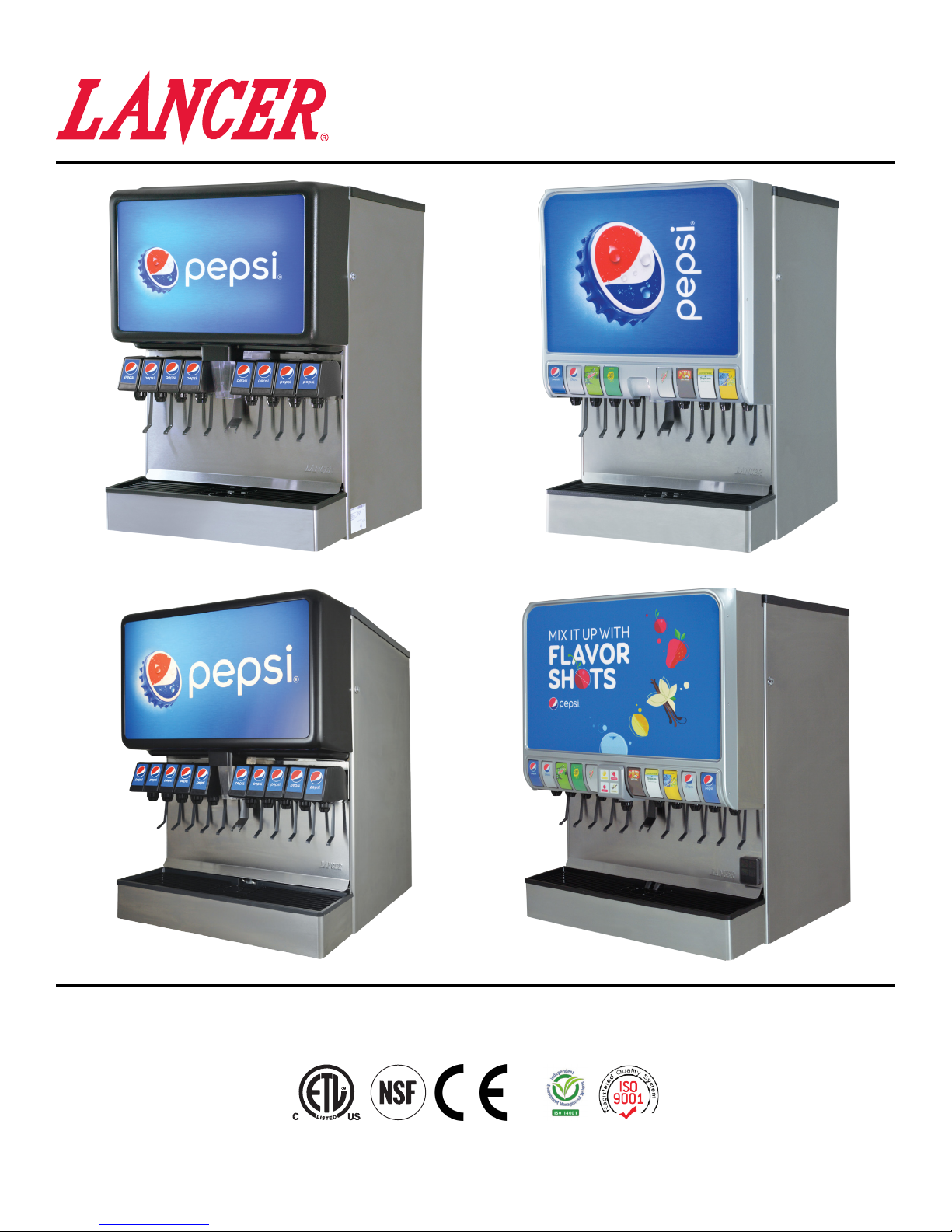
Blue Star IBD CB Series 22”/25”/30”
Renew & Renew Shots IBD CB Series 25”/30”
- Blue Star CB Series 25” - Renew IBD CB Series 25”
- Blue Star CB Series 30” - Renew Shots CB Series 30”
Operation Manual
Lancer Corporation
6655 Lancer Blvd.
San Antonio, Texas 78219
800-729-1500
“Lancer” is the registered trademark of Lancer © 2018 by Lancer, all rights reserved.
4500
Tech Support/Warranty: 800-729-1550
®
email: custserv@lancercorp.com
web: lancercorp.com
Lancer PN: 28-0946/03
Revision: January 2018
Page 2

TABLE OF CONTENTS
ABOUT THIS MANUAL
This booklet is an integral and essential part of the product.
Please carefully read the guidelines and warnings contained
herein as they are intended to provide the user with essential
information for the continued safe use and maintenance of the
product. In addition, it provides GUIDANCE ONLY to the user
on the correct services and site location of the unit.
BEFORE GETTING STARTED
Each unit is tested under operating conditions and is thoroughly
inspected before shipment. At the time of shipment, the
carrier accepts responsibility for the unit. Upon receiving the
unit, carefully inspect the carton for visible damage. If
damage exists, have the carrier note the damage on the freight
bill and le a claim with carrier. Responsibility for damage to the
dispenser lies with the carrier.
The installation and relocation, if necessary, of this product must be carried out by qualied personnel with
up-to-date safety and hygiene knowledge and practical experience, in accordance with current regulations.
IMPORTANT SAFETY INSTRUCTIONS....................................3
Intended Use.......................................................................3
Power Warning....................................................................3
CO2 Warning........................................................................3
Water Notice........................................................................3
Automatic Agitation...............................................................4
SPECIFICATIONS AND FEATURES..........................................4
Blue Star IBD CB Series 22”................................................4
Blue Star/Renew IBD CB Series 25”...................................5
Blue Star/Renew IBD CB Series 30”...................................6
Features of the Blue Star IBD CB Series 22”/25”/30”..........7
General Systems Overview - Remote Syrup Pumps...........7
PRE-INSTALLATION CHECKLIST.............................................8
INSTALLATION.....................................................................8-15
Unpacking the Dispenser.....................................................8
Selecting/Preparing a Counter Location..............................9
Installing an Icemaker.........................................................10
Dispenser Installation....................................................10-11
Remote Pump Installation...................................................11
Installing Remote Syrup Pumps - Bag in Box....................12
Installing CO2 Supply..........................................................13
Dispenser Setup.................................................................14
Adjust Water Flow Rate & Syrup/Water Ratio....................15
CLEANING AND SANITIZING............................................16-19
General Information...........................................................16
Cleaning and Sanitizing Solutions.....................................16
Daily Cleaning....................................................................16
Ice Bin Cleaning - Start-Up and Monthly............................17
Cleaning and Sanitizing Syrup Lines-Bag in Box...............17
Cleaning and Sanitizing Flavor Shot Lines........................17
Cleaning and Sanitizing Nozzles.......................................18
Cleaning and Sanitizing Flavor Shot Nozzle.....................18
Ice Chute Cleaning............................................................19
TROUBLESHOOTING.........................................................19-22
Valve/Flavor Shot Troubleshooting...............................19-21
Ice Bin/Ice Chute/Carbonator Pump Troubleshooting........21
Remote Syrup/Flavor Shot Pump Troubleshooting............22
ILLUSTRATIONS AND PART LISTINGS............................23-27
Main Unit Assembly - 22”/25”/30”......................................23
Flavor Shot Module Assembly............................................24
Plumbing Diagram - 22”.....................................................25
Plumbing Diagram - 25”.....................................................25
Plumbing Diagram - 30” 8 Valve........................................26
Plumbing Diagram - 30” 10 Valve......................................26
Wiring Diagram..................................................................27
DISPENSER DISPOSAL..........................................................27
READ ALL SAFETY INSTRUCTIONS BEFORE USING THIS UNIT.
This manual contains important safety information and all applicable safety precautions must be observed. To reduce
the risk of re, electric shock, damage to the equipment or personal injury when using this unit all instuctions/warnings
on the product being used must be followed:
! WARNING
Text following the Warning signal indicates a
hazardous situation, which if not avoided, will result
in death or serious injury. Be sure to read all Warning
statements before proceeding with the installation.
! CAUTION
Text following the Caution signal indicates a
hazardous situation, which if not avoided, could result
in death or serious injury. Be sure to read the Caution
statements before proceeding with the installation
2
! ATTENTION
Text following the Attention signal addresses a
situation that if not followed could potentially damage
the equipment. Be sure to read the Attention
statements before proceeding
NOTE
Text following the Note signal provides you with
informationthatmayhelpyoumoreeectivelyperform
the installation procedures within this manual.
Disregarding information will not cause damage or
injury, however it may limit the performance of the
dispenser.
Page 3
IMPORTANT SAFETY INSTRUCTIONS
! Intended Use
• The dispenser is for indoor use only
• This appliance is intended to be used in commercial
applications such as restaurants or similar.
• This appliance should not be used by children or
inrm persons without supervision.
• This appliance is not intended for use by persons
(including children) with reduced physical, sensory
or mental capabilities, or lack of experience and
knowledge, unless they have been given supervision
or instruction concerning use of the appliance by a
person responsible for their safety.
• This appliance can be used by children aged from 8
years and above and persons with reduced physical,
sensory or mental capabilities or lack of experience
and knowledge if they have been given supervision or
instruction concerning use of the appliance in a safe
way and understand the hazards involved.
• Cleaning and user maintenance shall not be
performed by children without supervision.
• This unit is not a toy and children should be advised
not to play with the appliance.
• The min/max ambient operating temperature for the
dispenser is 40°F to 105°F (4°C to 41°C).
• Do not operate unit below minimum ambient operation
conditions.
• Should freezing occur, cease operation of the unit and
contact authorized service technician.
• The maximum tilt for safe operation is 5°.
• This appliance must be installed and serviced by a
professional.
5 Carbon Dioxide (CO2)
• WARNING: Carbon Dioxide (CO2) is a colorless,
noncombustible gas with a light pungent odor. High
percentages of CO2 may displace oxygen in the
blood.
• WARNING: Prolonged exposure to CO
Personnel exposed to high concentrations of CO2 gas
will experience tremors which are followed by a loss
of consciousness and suocation.
• WARNING: If a CO
ventilate the contaminated area before attempting to
repair the leak.
gas leak is suspected, immediately
2
• WARNING: Strict attention must be observed in the
prevention of CO2 gas leaks in the entire CO2 and soft
drink system.
can be harmful.
2
F Power
• Follow all local electrical codes when making
connections.
• Check the dispenser name plate label, located behind
t h e s p l a s h p l a t e , f o r t h e c o r r e c t e l e c t r i c a l r e q u i r e m e n t s
of unit. DO NOT plug into a wall electrical outlet
unless the current shown on the serial number plate
agrees with local current available.
• Each dispenser must have a separate electrical
circuit.
• DO NOT use extension cords with this unit.
• DO NOT ‘gang’ together with other electrical devices
on the same outlet.
• WARNING: Always disconnect electrical power to the
unit to prevent personal injury before attempting any
internal maintenance.
• The resettable breaker switch should not be used as
a substitute for unplugging the dispenser from the
power source to service the unit.
• Only qualied personnel should service internal
components of electrical control housing.
• WARNING: Make sure that all water lines are tight and
units are dry before making any electrical connections
• If this dispenser is installed in an area that is
susceptible to ±10% variation of the nominal line
voltage, consider installing a surge protector or similar
protection device.
! Water Notice
• Provide an adequate, potable water supply. Water
pipe connections and xtures directly connected to
a potable water supply must be sized, installed, and
maintained according to federal, state, and local
codes.
• The water supply line must be at least a 3/8 inches
(9.525 mm) pipe with a minimym of 25 PSI (0.172
MPA) line pressure, but not exceeding a maximum of
65 PSI (0.448 MPA). Water pressure exceeding 65
PSI (0.448 MPA) must be reduced to 65 PSI (0.448
MPA).
• Use a lter in the water line to avoid equipment
damage and beverage o-taste. Check the water lter
periodically, as required by local conditions.
• CAUTION: The water supply must be protected by
means of an air gap, a backow prevention device
(located upstream of the CO2 injection system)
or another approved method to comply with NSF
standards. A leaking inlet water check valve will
allow carbonated water to ow back through the pump
when it is shut o and contaminate the water supply.
• CAUTION: Ensure the backow prevention device
complies with ASSE and local standards. It is the
responsibility of the installer to ensure compliance.
3
Page 4
! Automatic Agitation
• Units are equipped with an automatic agitation system and will activate unexpectedly.
• CAUTION: Do not place hands or foreign objects in the ice bin tank. Unplug the dispenser during servicing, cleaning, and
sanitizing.
• CAUTION: To avoid personal injury, do not attempt to lift the dispenser without assistance. For heavier dispensers, use a
mechanical lift.
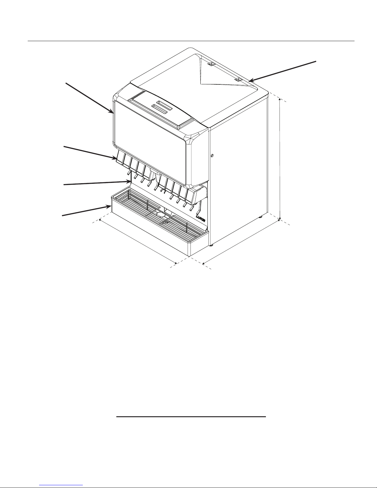
SPECIFICATIONS AND FEATURES
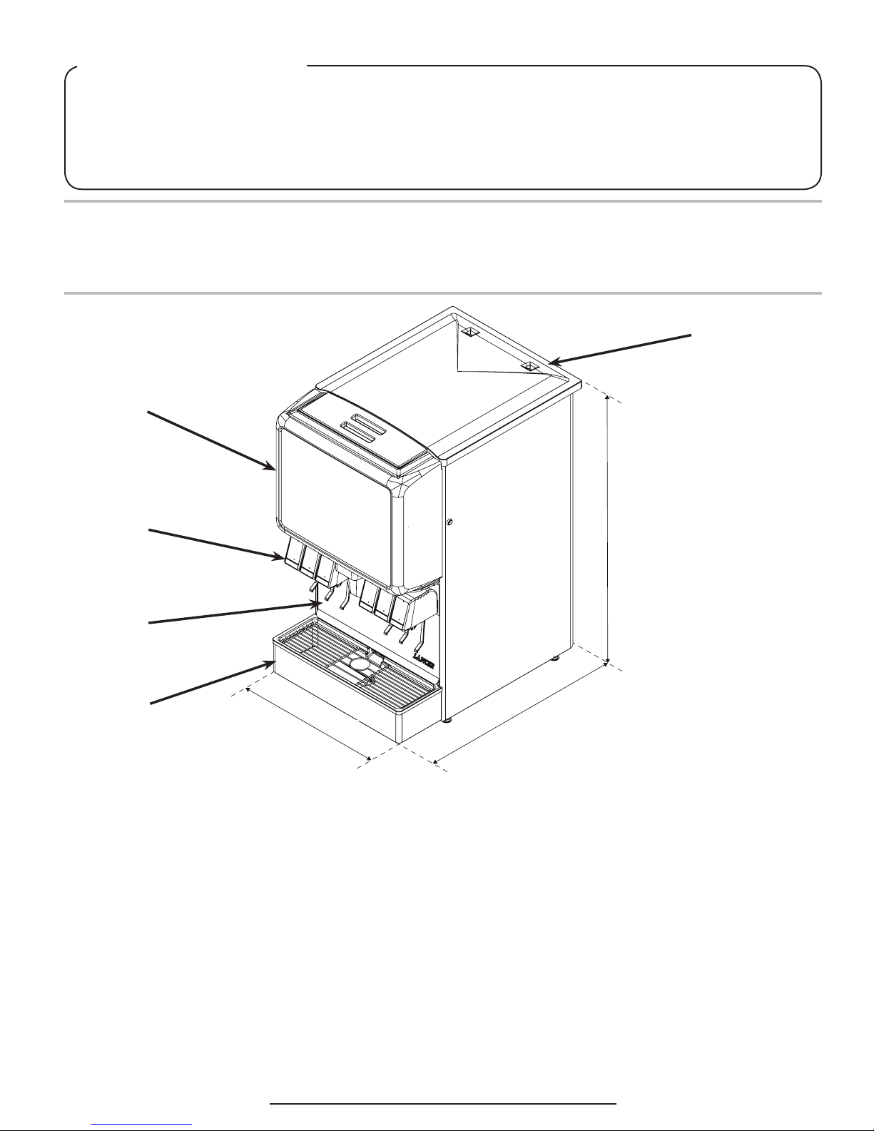
Blue Star IBD CB Series 22”
A
B
C
D
E
22.0 in.
DIMENSIONS
Width: 22.0 inches (559 mm)
Depth: 30.5 inches (775 mm)
Height: 40.25 inches (1022 mm)
WEIGHT
Shipping: 310 lbs (141 kg)
Empty (without Ice): 280 lbs (127 kg)
Ice Capacity: 200 lbs (91 kg)
ELECTRICAL
115 VAC / 60 Hz / 3.6 Amps
PLAIN WATER SUPPLY
40.25 in.
A. Top Cover
30.5 in.
B. Merchandiser
C. Valves
D. Splash Plate
E. Drip Tray
CARBONATED WATER SUPPLY
Min Flowing Pressure: 25 PSI (0.172 MPA)
Max Static Pressure: 65 PSI (0.448 MPA)
CARBON DIOXIDE (CO2) SUPPLY
Min Pressure: 70 PSIG (0.483 MPA)
Max Pressure: 80 PSIG (0.552 MPA)
FITTINGS
Carbonator Inlet: 3/8 inch barb
Plain Water Inlet: 3/8 inch barb
Brand Syrup Inlets: 3/8 inch barb
CO2 Inlet: 3/8 inch barb
Min Flowing Pressure: 75 PSIG (0.516 MPA)
4
This unit emits a sound pressure level below 70 dB
Page 5
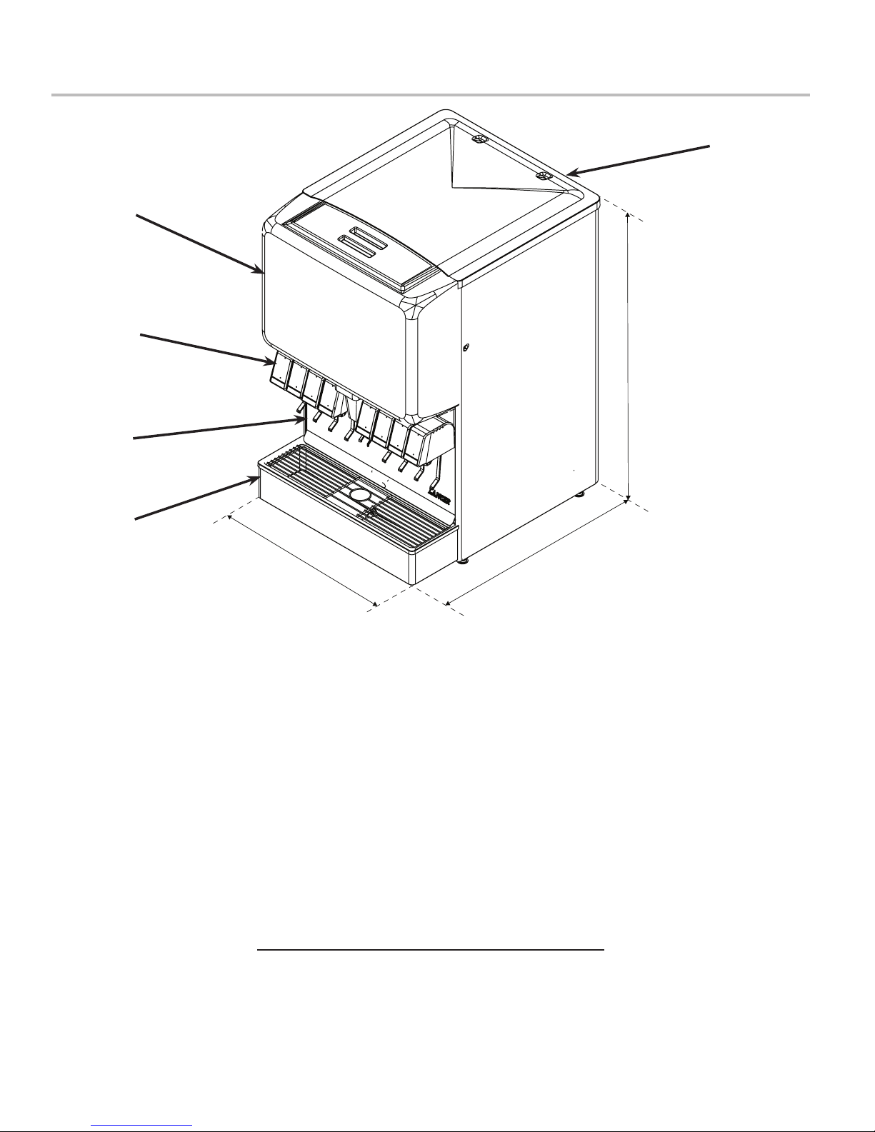
Blue Star IBD CB Series 25” & Renew IBD CB Series 25”
B
C
D
A
40.25 in.
E
25.0 in.
DIMENSIONS
Width: 25.0 inches (635 mm)
Depth: 30.5 inches (775 mm)
Height: 40.25 inches (1022 mm)
WEIGHT
Shipping: 331 lbs (150 kg)
Empty (without Ice): 295 lbs (134 kg)
Ice Capacity: 234 lbs (106 kg)
ELECTRICAL
115 VAC / 60 Hz / 3.6 Amps
PLAIN WATER SUPPLY
Min Flowing Pressure: 75 PSIG (0.516 MPA)
30.5 in.
A. Top Cover
B. Merchandiser
C. Valves
D. Splash Plate
E. Drip Tray
CARBONATED WATER SUPPLY
Min Flowing Pressure: 25 PSI (0.172 MPA)
Max Static Pressure: 65 PSI (0.448 MPA)
CARBON DIOXIDE (CO2) SUPPLY
Min Pressure: 70 PSIG (0.483 MPA)
Max Pressure: 80 PSIG (0.552 MPA)
FITTINGS
Carbonator Inlet: 3/8 inch barb
Plain Water Inlet: 3/8 inch barb
Brand Syrup Inlets: 3/8 inch barb
Flavor Shot Inlets: ““ inch barb
CO2 Inlet: 3/8 inch barb
This unit emits a sound pressure level below 70 dB
5
Page 6
Blue Star IBD CB Series 30” & Renew IBD CB Series 30”
B
C
D
A
40.25 in.
E
30.0 in.
DIMENSIONS
Width: 30 inches (762 mm)
Depth: 30.5 inches (775 mm)
Height: 40.25 inches (1022 mm)
WEIGHT
Shipping: 365 lbs (161 kg)
Empty (without Ice): 320 lbs (145 kg)
Ice Capacity: 290 lbs (132 kg)
ELECTRICAL
115 VAC / 60 Hz / 3.6 Amps
PLAIN WATER SUPPLY
Min Flowing Pressure: 75 PSIG (0.516 MPA)
30.5 in.
A. Top Cover
B. Merchandiser
C. Valves
D. Splash Plate
E. Drip Tray
CARBONATED WATER SUPPLY
Min Flowing Pressure: 25 PSI (0.172 MPA)
Max Static Pressure: 65 PSI (0.448 MPA)
CARBON DIOXIDE (CO2) SUPPLY
Min Pressure: 70 PSIG (0.483 MPA)
Max Pressure: 80 PSIG (0.552 MPA)
FITTINGS
Carbonator Inlet: 3/8 inch barb
Plain Water Inlet: 3/8 inch barb
Brand Syrup Inlets: 3/8 inch barb
Flavor Shot Inlets: ““ inch barb
CO2 Inlet: 3/8 inch barb
This unit emits a sound pressure level below 70 dB
6
Page 7
Features of the Blue Star IBD CB Series 22”/25”/30”
Cold Carbonation Capability
• Water is pre-chilled in the cold plate before entering the
carbonator tank.
• This allows it to absorb CO2 more eectively inside the
tank.
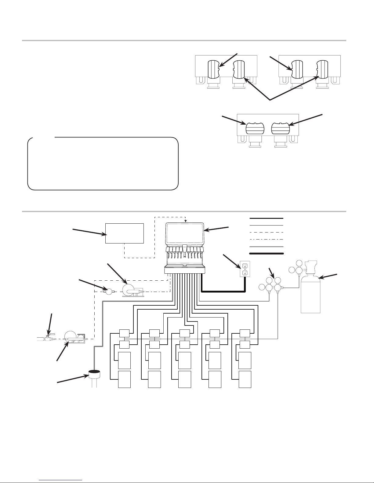
Three-Way Adjustable Back Blocks
• Allows for exibility between carbonated or plain water
drinks on the valves of your choice.
• To set adjustable back blocks, turn the shut-o stem to the
desired location, refer to the image below:
D
NOTE
Thereis100%exibilityonthe22”,6valveandthe30”
8 valve dispensers.
The30”,10valveandthe25”8valvedispensers
have space restrictions, so the two center valves are
plumbed only for carbonated watered drinks and are
non-adjustable.
General System Overview - Remote Syrup Pumps
I
E
D
A
H
J
B
C
E
A. Plain Water ON D. Water Closed
B. Carb Water ON E. Syrup Closed
C. Syrup ON
Syrup Line
CO2 Line
Plain Water Line
Carb Water Line
Drain Line
Electrical
K
110
L
75
75
A
F
F
B
C
G G G G G
G G G G G
A. Water Source
B. Water Booster
F
F
F F
F F
F
F
C. Floor Drain
D. Water Regulator
E. Remote Pump
F. Syrup Pump
G. BIB Syrup Containers
H. Dispenser
I. Icemaker (Optional)
J. Electrical Outlet
K. CO2 Regulator
L. CO2 Source
7
Page 8
PRE-INSTALLATION CHECKLIST
TOOLS REQUIRED:
Oetiker Pliers
Tubing Cutters
Wrench
Slotted Screwdriver
Phillips Screwdriver
Drill
BIB SYSTEM:
BIB Rack
BIB Syrup Boxes
BIB Regulator Set
BIB Connectors
POST MIX ACCESSORIES:
High Pressure CO2 Regulator
Low Pressure CO2 Regulator
Manifold
CO2 Supply
Chain for CO2 Tank
Beverage Dispenser
Beverage Tubing
Oetiker Clamp Fittings
Water Booster (Lancer PN:
82-3401 or MC-163172
Water Regulator (supplied with
unit)
CONSIDER THE FOLLOWING
BEFORE INSTALLATION:
Location of Water Supply Lines
Location of Drain
Location of Electrical Outlet
Location of Heating and Air
Conditioning Ducts
Do you have enough space to
install the dispenser?
Is countertop level?
Can the countertop support the
weight of the dispenser? (Include
the weight of an ice machine plus
weight of ice, if necessary)
Is dispenser located away from
direct sunlight or overhead
lighting?
INSTALLATION
Read This Manual
This manual was developed by Lancer Corporation as a reference guide for the owner/operator and installer of this dispenser.
Please read this manual before installation and operation of this dispenser. See pages 20 - 23 for troubleshooting or service
assistance. If the service cannot be corrected please call your Service Agent or Lancer Customer Service. Always have your
model and serial number available when you call.
Unpacking the Dispenser
1. Set shipping carton upright on the oor then cut package
banding straps and remove.
2. Open top of carton and remove interior packaging.
3. Lift carton up and o of the unit.
4. Remove plywood shipping base from unit by moving unit so
that one side is o the counter top or table allowing access
to screws on the bottom of the plywood shipping base.
NOTE
If unit is to be transported, it is advisable to leave the
unit secured to the plywood shipping base.
5. Remove accessory kit and loose parts from ice
compartment.
NOTE
Inspect unit for concealed damage. If evident, notify
deliveringcarrierandleaclaimagainstthesame.
6. If leg kit has been provided, assemble legs by tilting unit.
! ATTENTION
DO NOT LAY UNIT ON ITS SIDE OR BACK
8
Page 9
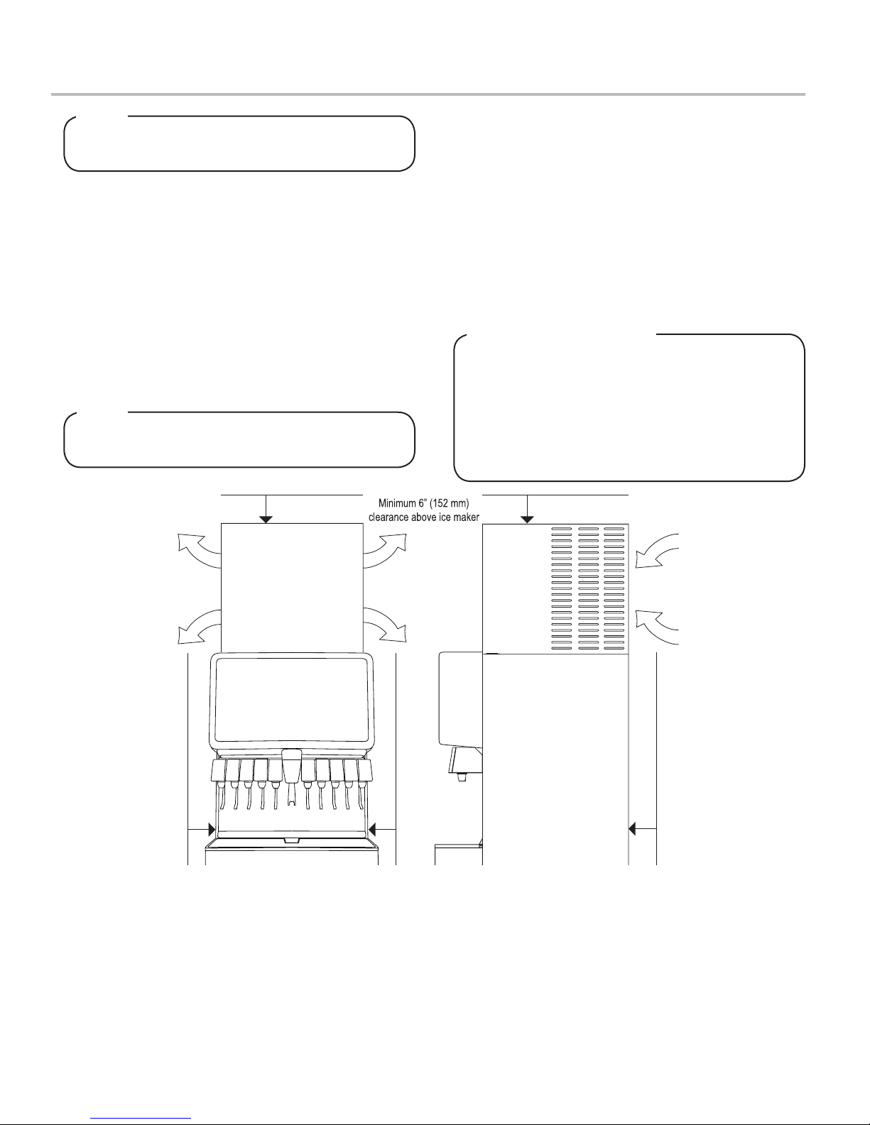
Selecting/Preparing a Counter Location
A
I
R
O
U
T
A
I
R
O
U
T
A
I
R
I
N
A
I
R
O
U
T
A
I
R
I
N
A
I
R
O
U
T
6” (152 mm) clearance
6” (152 mm) clearance
6” (152 mm) clearance
NOTE
The dispenser should only be installed in a location
where it can be overseen by trained personnel
1. Select a level, well ventilated location that is in close
proximity to a properly grounded electrical outlet, within ve
(5) feet (1.5 m) of a drain, a water supply that meets the
requirements shown in the Specications section found on
pages 4-6, away from direct sunlight or overhead lighting,
and has sucient clearance for air circulation.
2. Sucient clearance must be provided, if an ice maker is not
installed, to allow lling ice compartment from a ve gallon
bucket (a minimum of 16 inches is recommended).
3. The selected location should be able to support the weight
of the dispenser, ice and possibly an icemaker being
installed after counter cut out is made. Total weight (with
icemaker) for this unit could exceed 800 pounds (363.6kg).
NOTE
Lancer does NOT recommend the use of shaved or
akeiceinthedispenser.
4. Unit may be installed directly on countertop or on legs. If
installed directly on the counter, unit must be sealed to the
countertop with an FDA approved sealant. If an icemaker is
to be mounted on top of dispenser, do not install dispenser
on legs.
5. Select a location for the remote pump deck, remote syrup
pumps, remote avor shot syrup pumps (if necessary), CO2
t a n k , s y r u p c o n t a i n e r s , a n d w a t e r l t e r ( r e c o m m e n d e d ) .
Please see General System Overview on page 5 for
reference.
6. U s i n g C o u n t e r C u t o u t T e m p l a t e p r o v i d e d , c u t o u t r e q u i r e d
opening for the water, syrup, and CO2 lines in the
designated dispenser location.
Leveling the Dispenser:
In order to facilitate proper dispenser drainage,
ensure that the dispenser is level, front to back and
side to side. Place a level on the top of the rear edge
of the dispenser. The bubble must settle between the
level lines. Repeat this procedure for the remaining
three sides. Level unit if necessary. For optimum
performance place the unit at a 0° tilt. The maximum
tilt is 5°.
9
Page 10

Installing an Icemaker (if necessary)
4”
Attach Bin Stat Bracket As Shown Recommended Bin Stat Attachment
Bulb Tube
! ATTENTION
When installing an icemaker on the dispenser, use
a bin thermostat to control the ice level (see below).
This will prevent damage to the dispensing
mechanism. The bracket for mounting a thermostat is
located in the ice bin. During the automatic agitation
cycle and while dispensing ice, ensure there is adequate space between the top of the ice level and the
bottom of the icemaker so the ice can move without
obstruction. Contact your icemaker manufacturer for
information on a suitable bin thermostat.
1. Install the icemaker per manufacturer specications. Points
of consideration include drainage, ventilation, and drop
zones.
2. An adapter plate is required when installing an icemaker.
Contact your Sales Representative or Lancer Customer
Service for more information.
3. A bin thermostat is required in order to control the level of
ice in the dispenser (Refer to ATTENTION). Contact your
icemaker manufacturer to obtain the correct bin thermostat.
4. Bin thermostat should be a minimum of 2” below the top
edge of the dispenser. The preferred location of the bin
thermostat is on the left side wall.
! ATTENTION
Failure to use an ice bin thermostat will not only void
your IBD’s warranty but will result in the inability to
control the level of ice in the ice bin which can cause
damage to your dispenser.
5. Ensure the icemaker is installed properly to allow for
removal of the Merchandiser.
6. Ensure manual ll is accessible.
7. Clean and maintain icemaker per manufacturer’s
instructions.
Dispenser Installation
1. Remove the cup rest, drip tray, splash plate, merchandiser,
and top cover from the unit.
2. Route appropriate tubing from the water source to the plain
water inlet at the front of the unit and connect tubing to inlet
using the oetiker pliers and ttings,(see Plumbing Diagrams
on the front of the unit or on pages 26-27 for reference).
D
C
3. Connect tubing to water source then ush water lines to
check for leaks.
B
A
A. Oetiker Pliers
B. Fitting
C. Tubing
D. Syrup/Water
Inlet
4. Route appropriate tubing from the remote pump deck to the
carbonated water inlet and connect tubing to inlet.
5. Route appropriate tubing from the syrup pump location to
the syrup inlets and connect tubing to all syrup inlets.
6. For units with a avor shot module, route appropriate tubing
from the avor shot pump location to the avor shot inlets at
the front of the unit and connect tubing to inlets.
7. Route appropriate tubing from the CO2 source location to
the CO2 inlet on the unit and connect tubing to inlet.
C
A. CO2 Inlet
B. Fitting
B
A
C. Tubing
10
Page 11

8. Route the power supply cord to a grounded electrical outlet
of the proper voltage and amperage rating.
! WARNING
DO NOT PLUG UNIT INTO GROUNDED ELECTRICAL
OUTLET AT THIS TIME. Make sure that all water lines
are tight and unit is dry before making any electrical
connections
9. Route drain hose from designated open type drain to tting
on Drip Tray and connect hose to tting.
10. Reattach Drip Tray/Cup Rest to unit.
! CAUTION
Drain line must be insulated with a closed cell
insulation. Insulation must cover the entire length of
thedrainhose,includingttings.Thedrainshouldbe
installed in such a manner that water does not collect
in sags or other low points, as condensation will form.
Remote Pump Installation
C
A. Drain Fitting
A
B
B. Drain Line
C. Drip Tray
! ATTENTION
Pouring hot water into drain may cause the Drain
Tube to collapse. Allow only luke warm or cold water
to enter Drain Tube. Pouringcoeeteaandsimilar
substances into drain may cause the Drain Tube to
becomecloggedwithcoeeorteagrounds,orother
solid particles.
1. If necessary, install water booster (Lancer PN MC-163172)
between water supply and the unit.
2. Using tubing cutters, cut water line and install tee tting,
then route appropriate tubing from the remote pump
location to the tee tting at water line.
A. Tee Fitting
D
B. Line to Plain Water Inlet
C. Line to Water Source
D. Line to Remote Pump
B
C
A
3. Connect line from tee tting at water line to the remote
pump deck inlet regulator.
C
4. Complete the carbonated water line connection, installed in
the previous section, between the remote pump deck and
carbonated water inlet on the unit.
D
A
B
C
5. Install a shut-o valve in the water line feeding the deck. If a
separate water line is run for plain water, ensure that it also
has a shut-o valve.
A. Oetiker Pliers C. Pump Inlet
B. Line to Unit D. Pump Outlet
D
A
A. Oetiker Pliers C. Pump Inlet
B. Line to Tee Fitting D. Pump Outlet
B
11
Page 12

Installing Remote Syrup Pumps - Bag In Box
1. Install BIB rack and remote pumps according to
manufacturers’ instructions.
2. Once pumps and BIB rack are installed, measure and cut
tubing to length between the pump CO2 inlets, then connect
tubing to all pumps.
A
C
B
D
3. Using tubing cutters, cut any pump CO2 supply line and
install tee tting, then route appropriate tubing from the CO2
supply to the tee tting at syrup pumps.
D
A. Syrup Pump
B. CO2 Line
C. Fitting
D. Oetiker Pliers
A. Tee Fitting
B. Line to Syrup Pump
C. Fitting
D. Line to CO2 Supply
B
C
A
5. Install BIB (bag in box) connectors onto the syrup pump
inlet tubing.
! ATTENTION
Use proper connector for syrup manufacturer
A
B
D
6. Connect syrup BIBs to connectors. Repeat for each syrup
line/pump and each avor shot line/pump.
C
A. Syrup Pump Inlet
B. Fitting
C. BIB Connector
D. Oetiker Pliers
4. Connect tubing from dispenser syrup inlet to the syrup
pump outlet tting. Repeat for each syrup line/pump and
avor shot line/pump.
C
A. Syrup Pump Outlet
B. Syrup Pump
A
C. Fitting
12
C
A
B
A. Syrup Pump Inlet
B. BIB Connector
C. BIB Syrup Container
B
Page 13

Installing CO2 Supply
1. Connect high pressure CO2 regulator assembly to CO2
cylinder or bulk system.
! ATTENTION
Before installing regulator, assure that a seal (washer
or o-ring) is present in regulator attachment nut.
A
C
D
B
A. CO2 Regulator
- Thread regulator nut on to tank,
then tighten nut with wrench
2. Connect a 1/4” nut, stem and seal to CO2 regulator outlet.
B. Outlet
C. Wrench
D. CO2 Supply
A
4. Connect tubing routed from the CO2 inlet at the unit to one
of the low pressure CO2 regulator manifold outlets.
5. Connect tubing routed from the tee at the syrup pumps
to the second outlet of the low pressure CO2 regulator
manifold.
C
D
A
6. Using a wrench, loosen lock nut on the regulator
adjustment screw of the high pressure CO2 regulator
connected to the source, then using a screwdriver back out
lock nut screw all the way.
A. Line to Dispenser
B. Line to Syrup Pumps
C. Line to CO2 Regulator
D. CO2 Regulator Manifold
B
B
D
C
3. Route appropriate tubing from the low pressure CO2
regulator manifold location to the 1/4” nut, stem on the high
pressure CO2 regulator attached to source and connect
tubing.
A. CO2 Regulator
B. Wrench
C. 1/4” nut, Stem
D. CO2 Supply
! ATTENTION
A dedicated CO2 regulator is required to supply the
CO2 inlet at the unit as well as to all syrup pumps.
A. CO2 Regulator
A
B. Fitting
C. Line to CO2 Regulator
Manifold
D. Oetiker Pliers
! WARNING
DO NOT TURN ON CO2 SUPPLY AT THIS TIME
B
A
C
7. Repeat Step 6 for both low pressure CO2 regulators on the
regulator manifold routed to the unit and the syrup pumps.
A. CO2 Regulator
B. Screwdriver
C. Regulator Adjustment Screw
B
C
D
13
Page 14

Dispenser Setup
1. Turn on water source.
2. Open the pressure relief valve located on the front of the
unit, by ipping up on the valve cap lever. Hold open until
water ows from the relief valve then close (ip down) the
relief valve.
C
A
A. Pressure
B
3. Verify all Bag-In-Box contains syrup and check all
connections for leaks.
4. Place enough ice in the ice bin to ll approximately 1/2 of
the bin before plugging in the unit.
5. Connect unit power cord to grounded electical outlet.
Relief Valve
B. CO2 Inlet
C. Valve Lever
! WARNING
The dispenser must be properly electrically grounded
to avoid serious injury or fatal electrical shock. The
power cord has a three-prong grounded plug. If a
three-hole grounded electrical outlet is not available,
use an approved method to ground the unit. Follow
all local electrical codes when making connections.
Each dispenser must have a separate electrical circuit.
Do not use extension cords. Do not connect multiple
electrical devices on the same outlet.
6. Test the motor operation by pushing the ice chute lever until
agitator motor begins to turn.
7. Activate each valve to ensure a good ow of water is
achieved.
8. Ensure pump deck is turned OFF before turning on CO2.
9. Turn on CO2 at the source then, using a screwdriver, adjust
the high pressure regulator at the source to 110 PSI (0.758
MPA) then tighten locknut with wrench.
B
A
C
10. Adjust both of the low pressure regulators on the regulator
manifold to 75 PSI (0.517 MPA) then tighten locknut with
wrench.
11. Activate each valve until gas-out.
12. Plug in the remote carbonator pump deck, if not already
done so, and turn the switch to the ON position.
13. Activate each valve until the carbonator pump comes on.
Release the button, allow carbonator to ll and stop.
Repeat this process until a steady ow of carbonated water
is achieved.
A. Regulator Adjustment Screw
B. Adjust to 110 PSI (0.758 MPA)
C. Wrench
NOTE
The pump deck has a 3 minute timeout feature. If the
timeoutoccurs,turnthedeckOFFthenONbyipping
the switch on the control box.
NOTE
To check for CO2 leaks, close the valve on the CO2
cylinder and observe if the pressure to the system
dropswiththecylindervalveclosedforveminutes.
Open the cylinder valve after check.
14. Activate each valve to purge air from the syrup lines.
14
Page 15

Adjust Water Flow Rate & Syrup/Water Ratio
NOTE
Ensure there is ice on the cold plate and the lines are
coldbeforeattemptingtosettheowratesonthe
valves. The drink temperature should be no higher
than40°F(4.4°C)whenowratesareset.
NOTE
ForRenewwithandwithoutavorshotlines,itis
required to remove the merchandiser to gain access
to valves.
1. Remove valve cover from rst valve.
2. Close syrup shut-o at mounting block for rst valve, (see
page 5 for reference).
3. Using a Lancer ratio cup verify water ow rate (5 oz. in 4
sec.). Use a screwdriver to adjust if needed.
D
A
B
5. Install Lancer (yellow) syrup seperator (PN 54-0031) in
place of nozzle.
A
A. Syrup Seperator
B. Soda Lever
6. Re-open syrup shut-o at mounting block.
7. Activate valve to purge syrup until steady ow is achieved.
8. Using a Lancer brix cup, activate the valve and capture a
sample. Verify that the syrup level is even with the water
level. Use a screwdriver to adjust if needed.
A
B
Increase Decrease
C
A. Flow Control, Water
E
4. Remove nozzle by twisting counter clockwise and pulling
down, then remove diuser by pulling down.
B
A
B. Flow Control, Syrup
C. Nozzle (Diuser inside)
D. Retainer Clip
E. Soda Lever
C
A. Nozzle
B. Diuser
C. Soda Lever
B
C
A. Syrup Seperator
B. Ratio Cup
C. Verify Soda/
Water Level
9. Remove syrup seperator and reinstall nozzle. Replace
valve cover.
10. Repeat steps 1-8 for each valve.
11. Re-install merchandiser, splash plate, and top cover.
15
Page 16

CLEANING AND SANITIZING
General Information
• Lancer equipment (new or reconditioned) is shipped from the factory cleaned and sanitized in accordance with NSF guidelines.
The operator of the equipment must provide continuous maintenance as required by this manual and/or state and local health
department guidelines to ensure proper operation and sanitation requirements are maintained.
NOTE
ThecleaningproceduresprovidedhereinpertaintotheLancerequipmentidentiedbythismanual.Ifother
equipment is being cleaned, follow the guidelines established by the manufacturer for that equipment.
• Cleaning should be accomplished only by trained personnel. Sanitary gloves are to be used during cleaning operations.
Applicable safety precautions must be observed. Instruction warnings on the product being used must be followed.
! ATTENTION
• Use sanitary gloves when cleaning the unit and observe all applicable safety precautions.
• DO NOT use a water jet to clean or sanitize the unit.
• DO NOT disconnect water lines when cleaning and sanitizing syrup lines, to avoid contamination.
• DO NOT use strong bleaches or detergents; These can discolor and corrode various materials.
• DO NOT use metal scrapers, sharp objects, steel wool, scouring pads, abrasives, or solvents on the dispenser.
• DO NOT use hot water above 140° F (60° C). This can damage the dispenser.
• DO NOT spill sanitizing solution on any circuit boards. Insure all sanitizing solution is removed from the system.
Cleaning and Sanitizing Solutions
Cleaning Solution
Mix a mild, non-abrasive detergent (e.g. Sodium Laureth
Sulfate, dish soap) with clean, potable water at a temperature
of 90°F to 110°F (32°C to 43°C). The mixture ratio is one
ounce of cleaner to two gallons of water. Prepare a minimum of
ve gallons of cleaning solution. Do not use abrasive cleaners
or solvents because they can cause permanent damage to the
unit. Ensure rinsing is thorough, using clean, potable water at a
temperature of 90°F to 110°F. Extended lengths of product lines
may require additional cleaning solution.
Other Supplies Needed:
1. Clean cloth towels 2. Bucket 3. Extra nozzle 4. Sanitary gloves 5. Small brush (PN 22-0017)
Sanitizing Solution
Prepare the sanitizing solution in accordance with the
manufacturer’s written recommendations and safety guidelines.
The type and concentration of sanitizing agent recommended
in the instructions by the manufacturer shall comply with 40
CFR §180.940. The solution must provide 200 parts per million
(PPM) chlorine (e.g. Sodium Hypochlorite or bleach) and a
minimum of ve gallons of sanitizing solution should be
prepared.
Daily Cleaning
1. Using the cleaning solution, clean top cover and all exterior
stainless steel surfaces.
2. Clean exterior of dispensing valves and ice chute.
3. Remove cup rest then clean the drip tray and cup rest.
Replace cup rest and drip tray when nished.
4. Wipe clean all splash areas using a damp cloth soaked in
cleaning solution.
5. Clean beverage nozzles as specied by the section “Clean-
ing and Sanitizing Nozzles” on page 19.
16
Page 17

Ice Bin Cleaning - Start-Up and Monthly
NOTE
Refer to the Automatic Agitation Warning on page 4.
1. Disconnect power to the dispenser
2. Remove Top Cover.
3. Melt out any remaining ice from the bin.
4. Remove Agitator Pin from Agitator Shaft. Slide Agitator
Shaft rearward out Hub and pull out of rear Bearing to
remove.
5. Remove Ice Shroud by lifting and rotating out from beneath
the auger.
6. Use the Cleaning Solution, and a clean cloth or soft brush,
to clean all removable parts, sides of the Ice Bin, Auger,
and surface of the aluminum casting.
7. Using the Cleaning Solution and the sponge brush
provided, clean all interior surfaces of the ice chute and the
ice chute feed through.
8. Repeat Step 6 for all exterior surfaces of the dispenser.
9. Using hot water, thoroughly rinse away the cleaning
solution.
10. Wearing sanitary gloves, soak and clean cloth towel in
Sanitizing Solution and wash all surfaces of removable
parts, sides of the Ice Bin, Auger, and surface of the
aluminum casting.
11. Using the Sanitizing Solution and the sponge brush
provided, clean all interior surfaces of the ice chute and the
ice chute feed through.
12. Repeat Step 10 for all exterior surfaces of the dispenser.
13. Wearing sanitary gloves, reassemble all removable parts.
Ensure agitator clip is locked.
14. Fill Unit with ice and replace Top Cover.
15. Reconnect Dispenser to power source.
Cleaning and Sanitizing Syrup Lines - Bag in Box
1. Disconnect syrup lines from BIB’s
2. Place syrup lines, with BIB connectors, in a bucket of warm
water.
3. Activate each valve to ll the lines with warm water and
ush out syrup remaining in the lines.
4. Prepare Cleaning Solution described above.
5. Place syrup lines, with BIB connectors, into cleaning
solution.
6. Activate each valve until lines are lled with cleaning
solution then let stand for ten (10) minutes.
7. Flush out cleaning solution from the syrup lines using clean,
warm water.
8. Prepare Sanitizing Solution described above.
9. Place syrup lines into sanitizing solution and activate each
valve to ll lines with sanitizer. Let sit for ten (10) minutes.
10. Reconnect syrup lines to BIB’s and draw drinks to ush
solution from the dispenser.
11. Taste the drink to verify that there is no o-taste. If o-taste
is found, ush syrup system again.
! CAUTION
Following sanitization, rinse with end-use product
until there is no aftertaste. Do not use a fresh water
rinse. This is a NSF requirement. Residual sanitizing
solution left in the system creates a health hazard.
Cleaning and Sanitizing Flavor Shot Lines
1. Disconnect the four (4) avor injector lines from their bagin-box containers.
2. Place avor injector lines, with BIB connectors, in a bucket
of warm water.
3. Activate each avor injector line to ll the with warm water
and ush out any syrup remaining in the lines.
4. Prepare Cleaning Solution described on previous page.
5. Place avor injector lines, with BIB connectors, into clean-
ing solution.
6. Activate each avor injector line until lines are lled with
cleaning solution then let stand for ten (10) minutes.
7. Flush out cleaning solution from the avor injector lines
using clean, warm water.
8. Prepare Sanitizing Solution described on previous page.
9. Place avor lines into sanitizing solution and activate each
line to ll with sanitizer. Let sit for ten (10) minutes.
10. Reconnect syrup lines to bag-in-box container and draw
drinks to ush solution from the dispenser.
11. Taste the drink to verify that there is no o-taste. If o-taste
is found, ush syrup system again.
! CAUTION
Following sanitization, rinse with end-use product
until there is no aftertaste. Do not use a fresh water
rinse. This is a NSF requirement. Residual sanitizing
solution left in the system creates a health hazard.
17
Page 18

Cleaning and Sanitizing Nozzles
1. Disconnect power, so as to not activate valve while
cleaning.
2. Remove nozzle by twisting counter clockwise and pulling
down.
3. Remove diuser by pulling down.
B
A
C
A. Nozzle
B. Diuser
C. Soda Lever
4. Rinse nozzle and diuser with warm water.
5. Wash nozzle and diuser with cleaning solution then
6. Set nozzle and diuser aside and let air dry. DO NOT rinse
7. Reconnect diuser and nozzle.
8. Connect power.
9. Taste the drink to verify that there is no o-taste. If o-taste
Following sanitization, rinse with end-use product
Cleaning and Sanitizing Flavor Shot Nozzle
1. Disconnect power, so as to not activate valve while
cleaning.
2. Remove nozzle by twisting counter clockwise and pulling
down.
B
5. Wash nozzle and diuser with cleaning solution then
6. Set nozzle and diuser aside and let air dry. DO NOT rinse
7. Using a soft cloth and the cleaning solution described on
8. Using a soft cloth and the sanitizing solution described on
9. Connect power.
10. Taste the drink to verify that there is no o-taste. If o-taste
immerse in sanitizing solution and let sit for fteen (15)
minutes.
with water after sanitizing.
is found, ush syrup system again.
! CAUTION
until there is no aftertaste. Do not use a fresh water
rinse. This is a NSF requirement. Residual sanitizing
solution left in the system creates a health hazard.
immerse in sanitizing solution and let sit for fteen (15)
minutes.
with water after sanitizing.
page 9, thoroughly clean the avor shot panel of any
residual syrup.
page 9, thoroughly wipe down the avor shot panel and its
surrounding area and let air dry. DO NOT rinse with water
after sanitizing.
is found, ush syrup system again.
A
3. Remove diuser by pulling down.
4. Rinse nozzle and diuser with warm water.
18
A. Flavor Shot Nozzle
B. Flavor Panel
! CAUTION
Following sanitization, rinse with end-use product
until there is no aftertaste. Do not use a fresh water
rinse. This is a NSF requirement. Residual sanitizing
solution left in the system creates a health hazard.
Page 19

Ice Chute Cleaning
NOTE
It is recommended to perform this procedure monthly,
or more often if desired. Use the cleaning solution
described above. An alternate solution of one part
water to one part vinegar may be used to remove
water spots and calcium deposits.
1. Turn o power to the dispenser.
2. Remove Merchandiser.
3. Remove Ice Chute Lever, then remove Splash Plate
Assembly by lifting it up and out from the dispenser face.
NOTE
Always remove the ice chute lever before removing
the splash plate.
4. Remove the Ice Chute Assembly base by removing the four
(4) screws that attach it to the unit.
5. Prepare the Cleaning Solution.
6. Soak the Ice Chute Assembly in the solution.
7. Rinse and dry the Ice Chute Assembly thoroughly.
8. Reinstall the Ice Chute Assembly.
9. Reinstall Merchandiser and Splash Plate.
10. Reconnect power to the dispenser.
TROUBLESHOOTING
Valve/Flavor Shot Troubleshooting
TROUBLE CAUSE REMEDY
No product when valve is
activated.
1. Keyswitch is o or keyswitch harness is
disconnected.
2. No power to dispenser.
3. Malfunctioning switch assembly.
4. Malfunctioning power supply.
5. Malfunctioning PCB board.
6. Malfunctioning VersaPour valve.
1. Turn keyswitch on and/or reconnect
keyswitch harness.
2. Check internal breaker and incoming
power.
3. Replace switch assembly.
4. Check voltage to power supply. Check
fuses.
5. Replace PCB board.
6. Replace valve.
Water only dispensed, no
syrup. Or syrup only dispensed,
no water.
1. Syrup BIB empty.
2. Water or syrup shuto on mounting block
not fully open.
3. Improper or inadequate water or syrup
supply.
4. CO2 pressure to syrup pump too low.
5. Stalled or inoperative BIB pump.
6. Kinked line.
7. CO2 regulator malfunction.
1. Replace syrup BIB as required.
2. Open shuto completely.
3. Remove valve from mounting block &
open shutos slightly. Check water &
syrup supply. If no supply, check unit for
other problems. Ensure BIB connection is
engaged.
4. Check the CO2 pressure to the pump to
ensure it is between 70-80 PSI (0.483-
0.552 MPA).
5. Check CO2 pressure and/or replace pump.
6. Remove kink or replace line.
7. Repair or replace CO2 regulator as
required.
19
Page 20

TROUBLE CAUSE REMEDY
Syrup only dispensed. No
water, but CO2 gas dispensed
with syrup.
Excessive foaming. 1. No ice in bin.
Low or no carbonation. 1. Low or no CO2.
1. Improper water ow to dispenser.
2. Carbonator pump motor has timed out.
3. Liquid level probe not connected properly
to PCB.
4. Defective PCB assembly.
5. Defective liquid level probe.
6. Weak or defective carbonator pump.
2. Incoming water or syrup temperature too
high.
3. CO2 pressure too high.
4. Water ow rate too high.
5. Nozzle and diuser not clean.
6. Air in BIB lines.
2. Low water pressure.
3. Worn or defective carbonator pump.
4. Backow preventer not allowing water to
ow.
5. Probe malfunctioning.
6. PCB malfunctioning.
1. Check for water ow to dispenser.
2. Reset by turning the unit OFF, then ON
by using the circuit breaker on the power
supply or momentarily unplugging unit.
3. Check connections of liquid level probe to
PCB assembly.
4. Replace PCB assembly.
5. Replace liquid level probe.
6. Replace pump.
1. Fill bin with ice and allow coldplate to
re-stabilize.
2. Correct prior to dispenser.
3. Adjust CO2 pressure downward, but not
less than 70 PSI (0.483 MPA).
4. Re-adjust and reset ratio.
5. Remove and clean.
6. Bleed air from BIB lines.
1. Check CO2 supply. Adjust CO2 pressure to
70 PSI (0.483 MPA).
2. Need water booster kit.
3. Replace carbonator pump.
4. Replace backow preventer, noting
the ow direction arrow from pump to
coldplate.
5. Replace probe.
6. Replace PCB.
Erratic ratio. 1. Incoming water and/or syrup supply not at
minimum owing pressure.
2. Foreign debris in water and/or syrup ow
control.
3. CO2 regulator malfunction.
Insucient soda ow
(carbonated drinks).
Insucient water ow (plain
water drinks).
1. Insucient CO2 supply pressure.
2. Shuto on mounting block is not fully open.
3. Foreign debris in soda ow control.
1. Insucient incoming supply pressure.
2. Shuto on mounting block not fully open.
3. Foreign debris in water ow control.
4. Water ltration problem.
1. Check pressure and adjust.
2. Remove ow control from suspected valve
and clean out any foreign material to
ensure smooth spool movement.
3. Repair or replace CO2 regulator.
1. Verify incoming CO2 pressure is between
70 PSIG (0.483 MPA) and 80 PSIG (0.552
MPA)
2. Open shuto fully.
3. Remove soda ow control from valve and
clean out any foreign material to ensure
smooth spool movement.
1. Verify incoming supply water pressure to
plain water inlet is a minimum of 50 PSI
(0.345 MPA) and a maximum of 100 PSI
(0.689 MPA).
2. Open shuto fully.
3. Remove water ow control from valve and
clean out any foreign material to ensure
smooth spool movement.
4. Service water system as required.
20
Page 21

TROUBLE CAUSE REMEDY
Insucient syrup ow. 1. Insucient CO2 pressure to BIB pumps.
2. Shuto on mounting block not fully open.
3. Foreign debris in syrup ow control.
4. Defective BIB pump.
Water leakage around nozzle. 1. Damaged or improperly installed o-ring on
nozzle.
Miscellaneous leakage. 1. Gap between parts.
2. Damaged or improperly installed o-rings.
Miscellaneous leakage. 1. Gap between parts.
2. Damaged or improperly installed o-rings.
Water continually leaking at
connections.
1. Loose water connections.
2. Flare seal washer leaks.
1. Adjust CO2 pressure to BIB pumps to
80 PSI (0.552 MPA) (min. 70 PSI (0.483
MPA). Do not exceed manufacturer’s
recommendations.
2. Open shuto fully.
3. Remove syrup ow control from valve and
clean out any foreign material to ensure
smooth spool movement.
4. Replace pump.
1. If damaged, replace. If improperly
installed, adjust.
1. Tighten appropriate retaining screws.
2. Replace or adjust appropriate o-rings.
1. Tighten appropriate retaining screws.
2. Replace or adjust appropriate o-rings.
1. Tighten water connections.
2. Replace are seal washer.
Ice Bin/Ice Chute/Carbonator Pump Troubleshooting
TROUBLE CAUSE REMEDY
Water in ice bin. 1. Coldplate drain is obstructed. 1. Remove splash plate and drip tray to
obtain access to drain tubes and clear
accordingly.
Push ice chute; no response. 1. Dispenser not connected to power source.
2. Wiring harness not plugged in.
3. PC board defective.
4. Malfunctioning power supply.
Push ice chute, ice door opens
but motor does not run.
Push ice chute, motor runs but
ice door does not open.
1. Wiring harness not plugged in.
2. PC board defective.
3. Motor defective.
1. Solenoid not connected to PC board.
2. Solenoid defective.
3. PC board defective.
1. Connect dispenser to power source.
2. Plug in wiring harness.
3. Replace PC board.
4. Check voltage to power supply. Check
fuses.
1. Plug in wiring harness.
2. Replace PC board.
3. Replace motor.
1. Connect solenoid to PC board.
2. Replace solenoid.
3. Replace PC board.
Push ice chute, ice door opens,
motor runs, but ice does not
dispense, or ice is of poor
quality.
Noisy/cavitating carbonator
pump.
1. Dispenser is out of ice.
2. Agitator pin is missing or damaged.
3. Poor ice quality.
4. Key not installed on agitation shaft.
1. Insucient incoming water supply
pressure.
1. Fill dispenser with ice.
2. Replace agitator pin.
3. Service ice machine.
4. Install key on agitation shaft.
1. Verify incoming supply water pressure to
carbonator pump is min. of 25 PSI (0.172
MPA), max. of 50 PSI (0.345 MPA).
21
Page 22

Remote Syrup/Flavor Shot Pump Troubleshooting
TROUBLE CAUSE REMEDY
BIB pump does not operate
when dispensing valve is
opened.
BIB pump operating, but no
ow.
BIB pump continues to operate
when bag is empty.
BIB pump fails to restart after
bag replacement.
BIB pump fails to stop when
dispensing valve is closed.
1. Out of CO2, CO2 not turned on, or low CO2
pressure.
2. Out of syrup.
3. BIB connector not tight.
4. Kinks in syrup or gas lines.
1. Leak in syrup inlet or outlet line.
2. Defective BIB pump.
1. Leak in suction line.
2. Leaking o-ring on pump inlet tting.
3. Defective syrup BIB pump.
1. BIB connector not on tightly.
2. BIB connector is stopped up.
3. Kinks in syrup line.
1. Leak in discharge line or ttings.
2. Empty BIB.
3. Air leak on inlet line or bag connector.
1. Replace CO2 supply, turn on CO2
supply, or adjust CO2 pressure to 70-80
PSI (0.483-0.552 MPA).
2. Replace syrup supply.
3. Fasten connector tightly.
4. Straighten or replace lines.
1. Replace line.
2. Replace BIB pump.
1. Check BIB connector, if still leaking then
replace line.
2. Replace o-ring
3. Replace defective pump.
1. Tighten BIB connector.
2. Clean out or replace BIB connector.
3. Straighten or replace line.
1. Repair or replace discharge line.
2. Replace BIB.
3. Repair or replace.
22
Page 23

ILLUSTRATIONS AND PART LISTINGS
Main Unit Assembly - 22”/25”/30”
Part No. Description
85-4528CB-211P IBD25, 4500, 115/60, 8V
85-4546CB-211P IBD22, 4500, 115/60, 6V
85-4541CB-211P IBD30, 4500, 115/60, 10V
85-4548CB-211P IBD30, 4500, 115/60, 8V
6
5
4
10
9
8
11
12
7
13
14
3
2
1
Item Part No. Description
1 82-3186/01-01 Drip Tray Assy, IBD25, Black
- 82-4042-01 Drip Tray Assy, IBD22, Black
- 82-4374-01 Drip Tray Assy, IBD30, Black
2 30-8625 Splash Plate, IBD25
- 30-8466 Splash Plate, IBD22
- 30-10141 Splash Plate, IBD30
3 05-0999/01 Lever, Chute, IBD
4 05-2905/01 Chute, Lower, ACIB
5 05-2257/01 Chute, Upper, IC
6 05-3361/01 Merchandiser Sub Assy, IBD25
- 05-3364/01 Merchandiser Sub Assy, IBD22
- 05-3357/01 Merchandiser Sub Assy, IBD30
7 64-5031-01/01 PCB Assy, Backlight
15
18
17
8 30-12198 Reector, 21.5
9 05-1476/01-01 Lid, Front, IBD, Round, Black
10 05-1659-01 Lid, Back, IBD25, Black
- 05-1606-01 Lid, Back, IBD30, Black
- 05-1467/01-01 Lid, Back, IBD22, Black
11 23-1373 Agitator Assy, HEX
12 82-3556-01 Dispensing Wheel Assy
13 05-1310 Shroud, Dispensing Wheel
14 82-1618 Trim Assy
15 19-73310 LPV, 3.0, SSL
16 30-5876 Cover, Electrical Box
17 30-8873 Bracket, Light, Right
18 30-8872 Bracket, Light, Left
16
23
Page 24

Flavor Shot Module Assembly
16
9
10
11
12
13
8
18
17
15
14
4
5
3
2
6
1
Item Part No. Description
1 05-3242/01 Nozzle, Black
2 82-5139 Flavor Shot Assembly, FSM, Refresh
3 52-3822 Flavor Shot Keypad Panel Assembly
4 05-3287 Bonus Flavor Injector
5 05-3540-01 Refresh Merchandiser, FSM, 30”,
10 Valve
- 05-3542-01 Refresh Merchandiser, FSM, 30”,
8 Valve
- 05-3548-01 Refresh Merchandiser, FSM, 25”,
8 Valve
6 52-3701 ADA Button Panel Assembly
7 04-0774 Thumb Screw
8 30-12838 Flavor Shot Bracket
7
9 05-1385 Elbow Fitting, 0.5 Dole x 0.2 Barb
10 19-0262/03 LFCV Valve Assembly
11 82-2317/01 Mounting Block Assembly, SGL
12 30-12885 Faucet Plate, FSM, Refresh
13 01-2724 Adaptor, SS .175 Barb x Dole
14 52-3830 Solenoid/Valve Harness, FSM,
Refresh
15 52-3816/01 Control Board Housing, FSM,
Refresh
16 12-0550 Fuse Holder, In-Line, 500 V, 15 A
17 12-0643 LED Light Bar
18 12-0652 LED Driver, Ballast, 60 W, Mean Well
24
Page 25

Plumbing Diagram - 22”
Plumbing Diagram - 25”
*Syrup Lines Not Shown
*Syrup Lines Not Shown
25
Page 26

Plumbing Diagram - 30” 8 Valve
Plumbing Diagram - 30” 10 Valve
*Syrup Lines Not Shown
26
*Syrup Lines Not Shown
Page 27

Wiring Diagram - 115 Volt
Dispenser Disposal
To prevent possible harm to the environment from improper disposal, recycle the unit
by locating an authorized recycler or contact the retailer where the product was purchased.
Comply with local regulations regarding disposal of the refrigerant and insulation.
27
Page 28

Lancer Corp.
800-729-1500
Technical Support/Warranty: 800-729-1550
custserv@lancercorp.com
lancercorp.com
 Loading...