

Page 1
Volumetric Post-Mix Valve
STANDARD LEVER
Operation Manual
PN: 28-0301/05
SELF-SERVE LEVER
10011
14512
PORTION CONTROL
Technical Support/Warranty: 800-729-1550
“Lancer” is the registered trademark of Lancer © 2014 by Lancer, all rights reserved.
PUSH
PUSH BUTTON
Lancer Corp.
6655 Lancer Blvd.
San Antonio, Texas 78219
800-729-1500
custserv@lancercorp.com
lancercorp.com
Manual PN: 28-0301/05
APRIL 2012
FOR QUALIFIED INSTALLER ONLY
Page 2

ABOUT THIS MANUAL
This booklet is an integral and essential part of the product and should be handed over to the operator after the installation and preserved for any further consultation that may be necessary. Please read carefully the guidelines and warnings contained herein as they are intended to provide the user with essential information for the continued safe use
and maintenance of the product. In addition, it provides GUIDANCE ONLY to the user on the correct services and site
location of the unit.
The installation and relocation, if necessary, of this product must be carried out by qualied personnel with up-to-date
safety and hygiene knowledge and practical experience, in accordance with current regulations.
TABLE OF CONTENTS
SPECIFICATIONS................................................................................................................................3
1. PRICIPLE OF OPERATION........................................................................................................4
2. CLEANING AND SANITIZING INSTRUCTIONS.......................................................................5
3. VALVE SETUP.............................................................................................................................7
4. SYRUP RESTRICTOR SETTING...............................................................................................7
5. SYRUP PURGE PLUG...............................................................................................................7
6. PROGRAMMER OPERATING PROCEDURES.........................................................................8
7. PORTION CONTROL PROGRAMMING PROCEDURES..........................................................9
8. COVER AND ID PANEL...........................................................................................................10
9. VALVE.......................................................................................................................................11
10. LEVER ARM.............................................................................................................................11
11. NOZZLE/DIFFUSER.................................................................................................................12
12. CIRCUIT BOARD......................................................................................................................12
13. FLOWMETER...........................................................................................................................13
14. FLOW WASHER ASSEMBLY...................................................................................................14
15. SYRUP REGULATOR...............................................................................................................14
16. WATER SOLENOID ACCESS..................................................................................................15
17. WATER SOLENOID ASSEMBLY..............................................................................................17
18. SYRUP BODY ACCESS...........................................................................................................18
19. SYRUP SOLENOID ACCESS..................................................................................................20
20. SYRUP SOLENOID ASSEMBLY..............................................................................................21
21. TROUBLESHOOTING..............................................................................................................22
22. APPLIANCE DISPOSAL..........................................................................................................25
23. VOLUMETRIC VALVE ASSEMBLY..........................................................................................26
2
Page 3

ABOUT THE VALVE
THE VOLUMETRIC VALVE DISPENSES POST-MIX BEVERAGES ACCURATELY OVER A BROAD RANGE
OF PRESSURES AND SYRUP VISCOSITIES. CONFIGURATIONS, FROM A CUP LEVER TO A PORTION
CONTROL PANEL INTERFACE, ALLOW THE VOLUMETRIC VALVE TO FIT MANY DIFFERENT
APPLICATIONS. THE VOLUMETRIC VALVE MOUNTS TO A STANDARD LEV® BACK BLOCK AND
UTILIZES THE SAME COVER AS THE LEV®.
SPECIFICATIONS
FINISHED DRINK FLOW RATES:
• 3.0 ounces per sec (88.7 ml/sec), Standard
• 2.25 ounces per sec (66.5 ml/sec)
• 1.50 ounces per sec (44.4 ml/sec)
PRESSURE REQUIREMENTS:
Flowing pressure (at the valve)
Minimum Maximum
Water 40 psig 110 psig
(2.8 Kg/cm2) (7.7 Kg/cm2)
Syrup (Sugar) 20 psig 70 psig
(1.4 Kg/cm2) (4.9 Kg/cm2)
Syrup (Diet) 10 psig 70 psig
(0.7 Kg/cm2) (4.9 Kg/cm2)
ELECTRICAL REQUIREMENT:
24 VAC, 50/60 Hz
MOUNTING
Mounts on the same hole pattern with the same mounting screws as the following valves: Lancer LEV®
Cornelius SF-1 Dole SEV McCann Turbo Flo Jr. Dole FFV
MAINTENANCE TOOLS
When troubleshooting and accessing the Volumetric Valve, the following tools will be needed:
Standard
• #2 Phillips Head Screw Driver • Flat End Screw Driver
• Dow Corning® 111 Valve Lubricant & Sealant
• Volumetric Valve Hand Held Programmer (Lancer PN 52-1420/02; CCPN 532179)
Optional
• 3/16 inch Hex Socket Driver • Ohmmeter
BEFORE GETTING STARTED
Each unit is tested under operating conditions and is thoroughly inspected before shipment. At the time of
shipment, the carrier accepts responsibility for the unit. Upon receiving the unit, carefully inspect the carton
for visible damage. If damage exists, have the carrier note the damage on the freight bill and le a claim with
carrier. Responsibility for damage to the dispenser lies with the carrier.
3
Page 4
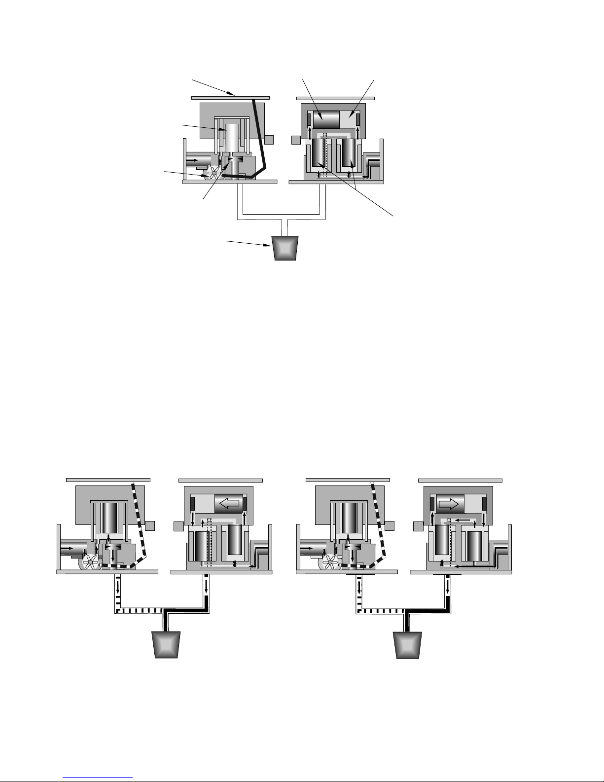
1. PRINCIPLE OF OPERATION
Syrup Chamber
Piston
Components:
S1
S1
S2
S2
Circuit Board
FIGURE 1. COMPONENTS
Water Syrup
Measuring
System
Water
Solenoid
Flowmeter
Flow Washer
Nozzle
W1
W1
S1
S1
S2
S2
Injecting
System
Syrup Solenoids
A. Three systems in the Volumetric Valve work together to maintain an accurate syrup to water ratio:
• The circuit board with its computer.
• The water measuring system.
• The syrup injecting system.
B. Set the ratio by using the hand held programmer (Lancer PN 52-1420/02; CCPN 532179).
C. When a customer activates the valve, the water starts owing to the nozzle. The ow washer en-
sures that the water does not ow too fast.
D. The paddle wheel in the owmeter begins to spin, sending signals to the circuit board (see below).
E. The computer on the circuit board monitors the signals and determines when to inject syrup into the
water stream. The circuit board energizes one syrup solenoid and then the other. This alternating
action injects a metered amount of syrup into the water. This happens seven to eight (7-8) times a
second (see Fig. 2 and 3).
F. The circuit board indicates which solenoid is activated with the LEDs mounted on the front of the
board. The green LED corresponds to the water solenoid and the red LEDs correspond to the syrup
solenoids.
FIGURE 2. OPERATION DIAGRAM - VALVE ON FIGURE 3. OPERATION DIAGRAM - VALVE ON
4
Page 5
S1
S1
S2
S2
W1
W1
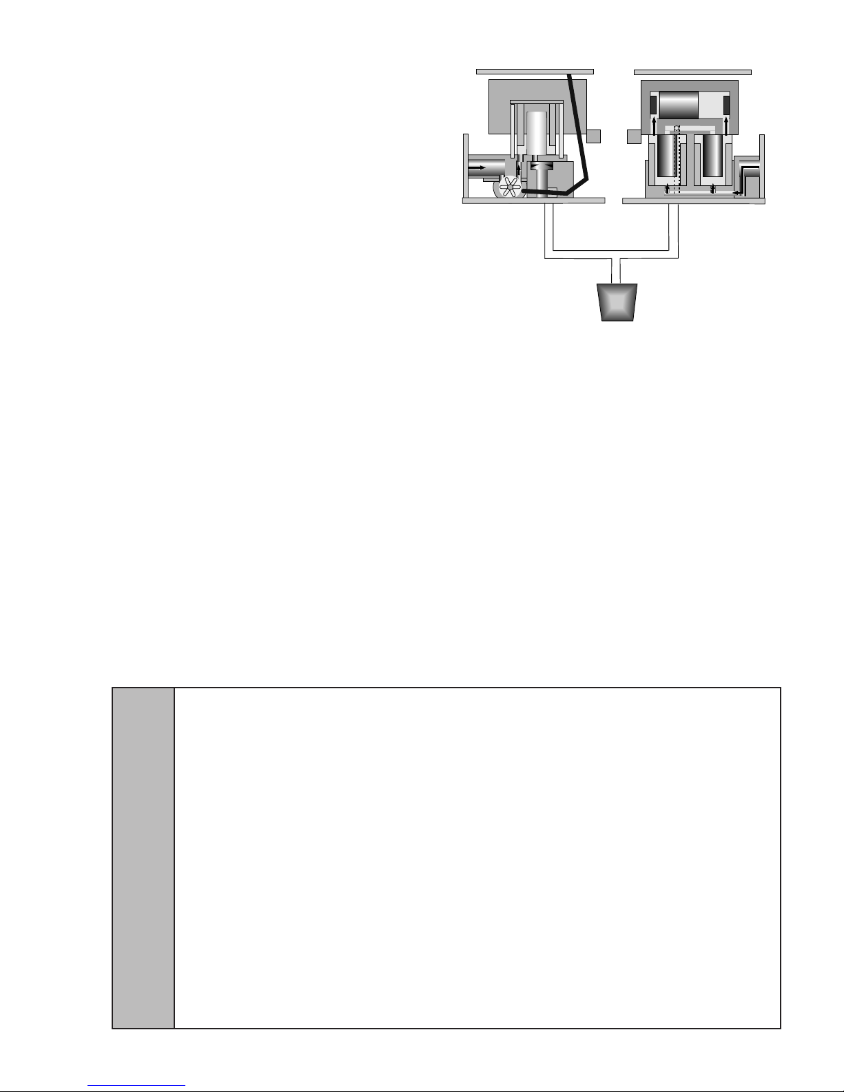
2. CLEANING AND SANITIZING INSTRUCTIONS
GENERAL INFORMATION
A. The cleaning and sanitizing procedures
provided pertain to the Lancer equipment
identied by this manual. If other
equipment is being cleaned, follow the
guidelines established by the manufacturer
for that equipment.
B. Lancer equipment (new or reconditioned) is
shipped from the factory cleaned and
sanitized in accordance with NSF
guidelines. The equipment must be cleaned
and sanitized after installation is complete.
The operator of the equipment must provide
continuous maintenance as required by this
manual and state and local health
department guidelines to ensure proper
operation and sanitation requirements are
FIGURE 4. OPERATION DIAGRAM - VALVE OFF
maintained.
C. Cleaning and sanitizing should be accomplished only by trained personnel. Sanitary gloves are to
be used during cleaning and sanitizing operations. Applicable safety precautions must be observed.
Instruction warnings on the product being used must be followed.
2.1 CLEANING SOLUTION
Mix a mild, non-abrasive detergent (e.g. Sodium Laureth Sulfate, dish soap) with clean, potable
water at a temperature of 90 to 110°F (32 to 43°C). The mixture ratio is one ounce of cleaner to two
gallons of water. Prepare a minimum of ve gallons of cleaning solution. Do not use abrasive
cleaners or solvents because they can cause permanent damage to the unit. Ensure rinsing is
thorough, using clean, potable water at a temperature of 90 to 110 degrees F. Extended lengths of
product lines may require additional cleaning solution.
2.2 SANITIZING SOLUTION
Prepare sanitizing solutions in accordance with the manufacturer’s written recommendations and
safety guidelines. The solution must provide 50 to 100 parts per million (PPM) chlorine (e.g. Sodium
Hypochlorite or bleach). A minimum of ve gallons of sanitizing solution should be prepared. Any
sanitizing solution may be used as long as it is prepared in accordance with the manufacturer’s
written recommendations and safety guidelines, and provides 50 to 100 parts per million (PPM)
chlorine.
WARNING IF A POWDER SANITIZER IS USED, DISSOLVE IT THOROUGHLY WITH HOT WATER PRIOR TO
ADDING TO THE SYRUP SYSTEM. ENSURE SANITIZING SOLUTION IS REMOVED FROM THE DISPENSER AS
INSTRUCTED. AVOID GETTING SANITIZING SOLUTION ON CIRCUIT BOARDS. DO NOT USE STRONG BLEACHES
OR DETERGENTS; THESE CAN DISCOLORAND CORRODE VARIOUS MATERIALS. DO NOT USE METAL
SCRAPERS, SHARP OBJECTS, STEEL WOOL, SCOURING PADS, ABRASIVES, OR SOLVENTS ON THE
DISPENSER. DO NOT USE HOT WATER ABOVE 140° F (60° C). THIS CAN DAMAGE THE DISPENSER.
ADVERTENCIA SI SE USA UN HIGIENIZADOR EN POLVO, DISUÉLVALO BIEN EN AGUA ANTES DE AGREGARLO
AL SISTEMA DE CONCENTRADO. EL USO DE AGUA CALIENTE CONTRIBUYE A DISOLVER LOS HIGIENIZADORES
EN POLVO. ASEGÚRESE DE HABER ELIMINADO LA SOLUCIÓN DE ESTERILIZACIÓN DEL
DISPENSADOR DE ACUERDO CON LAS INSTRUCCIONES. LOS RESIDUOS DE LA SOLUCIÓN DE
ESTERILIZACIÓN REPRESENTAN UN PELIGRO PARA LA SALUD. EVITE QUE LA SOLUCIÓN DE ESTERILIZACIÓN
LLEGUE A LAS PLACAS DE CIRCUITOS. NO USE LAVANDINAS NI DETERGENTES QUE PODRÍAN QUITAR EL
!
COLOR Y CORROER DISTINTOS MATERIALES. NO USE RASPADORES METÁLICOS, OBJETOS FILOSOS, LANA
DE ACERO, ESTROPAJOS, ABRASIVOS NI SOLVENTES EN EL DISPENSADOR. NO USE AGUA CALIENTE A MÁS
DE 140 ºF (60 ºC). PODRÍA DAÑAR EL DISPENSADOR.
AVERTISSEMENT AVANT L’INJECTION DANS LE SYSTÈME, IL FAUDRA QUE LA POUDRE SEPTIQUE SOIT
DISSOLUE ENTIÈREMENT DANS CHAUDE. L’EAU CHAUDE PERMETTRA UN MEILLEUR PROCÈS DE
DISSOLUTION. SUIVANT LES INSTRUCTIONS JOINTES, IL EST IMPÉRATIF QUE LA SOLUTION SEPTIQUE SOIT
ENTIÈREMENT ENLEVÉE. EVITEZ DE METTRE LA SOLUTION EN CONTACT AVEC LES CIRCUITS. N’UTILISEZ PAS
DE JAVELLISANTS OU DEDÉTERGENTS FORTS; CEUX-CI PEUVENT DÉCOLORER ET CORRODER DIVERS
MATÉRIAUX. N’UTILISEZ PAS DE RACLEURS EN MÉTAL, D’OBJETS POINTUS, DE LAINE D’ACIER, DE TAMPONS À
RÉCURER, D’ABRASIFS OU DE SOLVANTS SUR LE DISTRIBUTEUR. N’UTILISEZ PAS DE L’EAU CHAUDE DE PLUS
DE 140 DEGRÉS F (60 DEGRÉS C). CECI PEUT ENDOMMAGER LE DISTRIBUTEUR.
5
Page 6
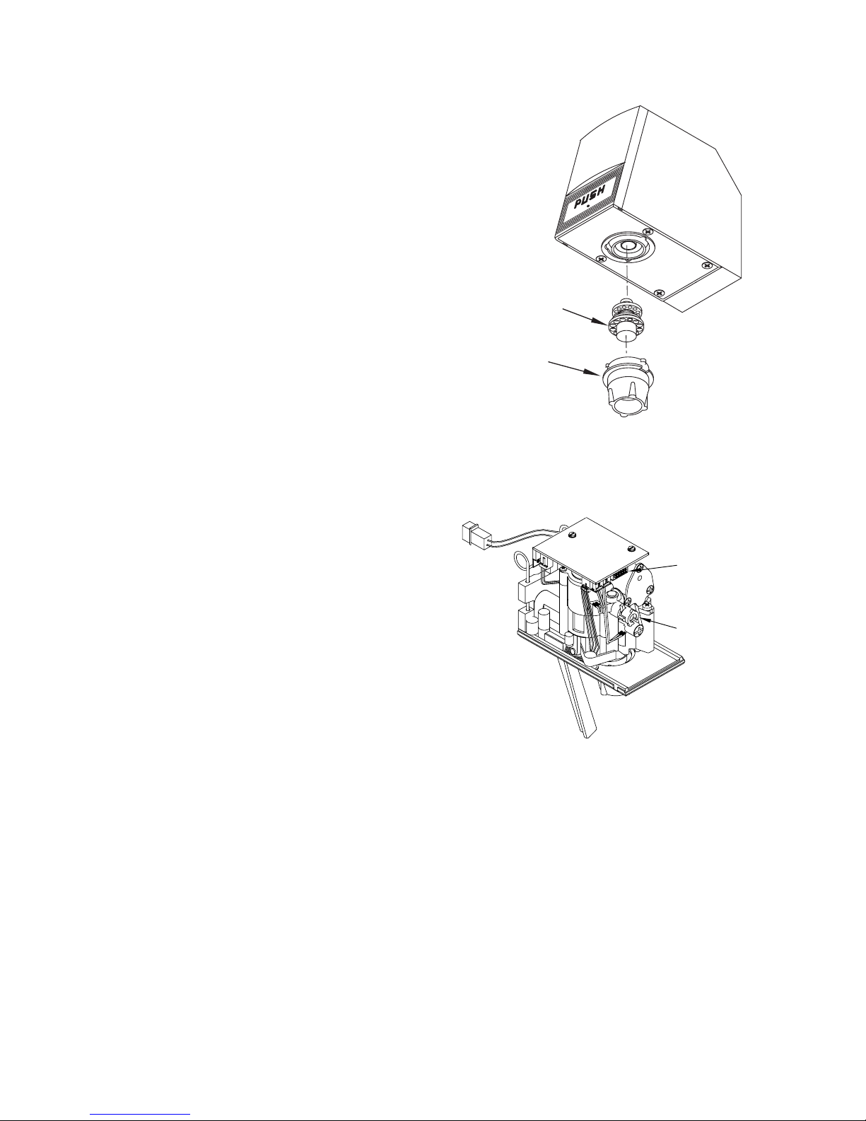
2.3 DAILY NOZZLE/DIFFUSER CLEANING (SEE FIGURE 5)
NOTE: Part Number in ( ) is a Coca-Cola PN
Plug (Programmer,
Syrup Restrictor
Portion Control,
Pushbutton, Syrup
Purge Plug)
Use the following procedures to clean the nozzle, and the
FIGURE 5. NOZZLE/DIFFUSER
diffuser assembly, each day:
A. Remove nozzle by twisting it counter-clockwise and
pulling it down.
B. Pull the diffuser assembly down to remove it from the
valve.
C. Wash the nozzle and diffuser with warm water.
D. If needed, apply 111 lubricant to the o-ring on the
diffuser assembly. Next, carefully press it into the
diffuser mounting area on the underside of the valve.
E. Install the nozzle by inserting it into the bottom plate
and twisting it clockwise to lock it in place.
2.4 MONTHLY NOZZLE/DIFFUSER SANITIZING
A. Disconnect power, so the valve will not be
Diffuser Assembly
54-0176/04
(24245)
inadvertently activated while cleaning.
B. Remove nozzle by twisting it counter-clockwise and
pulling it down.
C. Pull the diffuser assembly down to remove it from the
Nozzle
05-2053/01
(24246)
valve.
D. Wash the nozzle and diffuser with the cleaning
solution.
E. Immerse the nozzle and diffuser in a bath of the sanitizing solution for 15 minutes.
F. While the parts are in the sanitizing solution,
visually inspect around the nozzle mounting
FIGURE 6. NOZZLE/DIFFUSER
area on the valve for syrup residue. Using a
cloth or nozzle brush and warm water, clean
this area.
G. Wipe off the dispensing lever and any other
areas that may have been splashed by syrup.
H. Wearing sanitary gloves, remove, drain, and air
dry the nozzle and diffuser.
I. Wearing sanitary gloves, carefully press the
diffuser into the mounting area on the
underside of the valve.
J. Wearing sanitary gloves, install the nozzle by
inserting it into the bottom plate and twisting it
clockwise to lock it in place.
K. Connect power and replace cover. Valve is
ready for operation.
L. Draw drinks to ush residual sanitizing solution. Taste the beverage to verify that there is no off
taste. If an off taste is found, additional ushing may be required.
2.5 VALVE AND SYSTEM SANITIZING
A. The complete valve and dispenser system must be sanitized during initial installation. Follow
the manufacturer’s instructions when scheduling and conducting dispenser sanitizing. The
valve must be sanitized once every two weeks. The valve may remain on the dispensing tower
during the sanitizing process.
B. For syrup side line priming, and cleaning and sanitization procedures, refer to the Syrup Purge
Plug (Lancer PN 52-1912) in the Valve Set-Up Section.
6
Page 7
52-1912
SYRUP PURGE
3. VALVE SETUP
The following steps provide an overview of the valve set-up procedures:
A. Mount valve on back block (see Section 9).
B. Verify that power supply is 24 VAC, 50/60 Hz, then connect to valve.
C. Connect water (soda) and syrup supplies. Flowing pressures must meet valve specications (see
Specications, Page 3).
D. Set ratio and select carbonation. See Section 6 for hand held programmer procedures.
E. Set the syrup restrictor for either diet or sugar syrup (see Section 4).
F. Purge syrup lines using the hand held programmer (see Section 6).
G. Install valve cover, and if necessary, connect ID panel (see Section 8).
H. Activate valve to test dispensing.
4. SYRUP RESTRICTOR SETTING
A. SUGAR SYRUP AND DIET SYRUP FROM FIGALS: Restrictor out and down. Syrup restrictor is not
in use.
B. DIET SYRUP FROM BAG-IN-A BOX: Restrictor in and up. Syrup restrictor is in use.
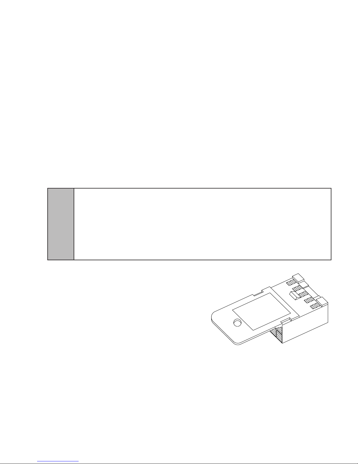
5. SYRUP PURGE PLUG
A. The Syrup Purge Plug (PN 52-1912), places the valve in continuous syrup side operation.
B. The targeted uses for the purge plug consist of priming the syrup line on an initial Volumetric Valve
install, and for cleaning and sanitization of the syrup side of the dispensing unit.
5.1 OPERATION OF THE SYRUP PURGE PLUG
CAUTION VALVE CONSUMES 12VA IN A CONTINUOUS SYRUP SIDE OPERATION. USING A STANDARD 75VA
TRANSFORMER, UP TO SIX (6) VOLUMETRIC VALVES CAN BE OPERATED IN SYRUP PURGE MODE
SIMULTANEOUSLY.
PRECAUCIÓN LA VÁLVULA CONSUME 12VA EN UNA OPERACIÓN LATERAL DE OPERACIÓN DEL JARABE, US-
ANDO UN TRANSFORMADOR ESTÁNDAR DE 75VA, SE PUEDEN OPERAR HASTA SEIS (6) VÁLVULAS
VOLUMÉTRICAS SIMULTÁNEAMENTE EN UN MODO DE PURGA DEL JARABE.
!
ATTENTION LA PUISSANCE ÉLECTRIQUE CONSOMMÉE PAR L’ÉLECTRO-VANNE EST DE L’ORDRE DE 12
VOLTS-AMPÈRES EN COURS DE TRAITEMENT CONTINU DU CÔTÉ SIROP. LORSQU’UN TRANSFORMATEUR
STANDARD DE 75 VOLTS-AMPÈRES SERA UTILISÉ, JUSQU’À SIX (6) VANNES VOLUMÉTRIQUES POURRONT
ÊTRE MISES EN OEUVRE SIMULTANÉMENT EN MODE PURGE.
A. Turn off electrical power to all valves.
B. Install syrup purge plugs into the valve or
valves to be primed or sanitized. The syrup
purge plug installs in the ten-pin connector of
the Volumetric Valve circuit board.
C. Turn on electrical power to the valves. At this
time, the syrup side of the valves will begin
continuous operation.
D. When through with the priming or sanitization
operation, syrup purge operation can be
stopped either of two ways:
Method 1: Turn off electrical power to all valves,
remove syrup purge plugs from the valves.
Turn on electrical power to all valves. Tap valve
lever or push button to ensure proper operation
of all valves.
Method 2: Remove syrup purge plug from the valves while they are in purge operation. In this
case, the valve may continue in the purge mode for up to six (6) seconds after removal of the
E. Using a standard 75 VA transformer, up to six (6) Volumetric Valves can be operated in the
plug (this is normal). Tap valve lever or push button to ensure proper operation of all valves.
syrup purge mode simultaneously.
FIGURE 7. SYRUP PURGE PLUG
7
Page 8
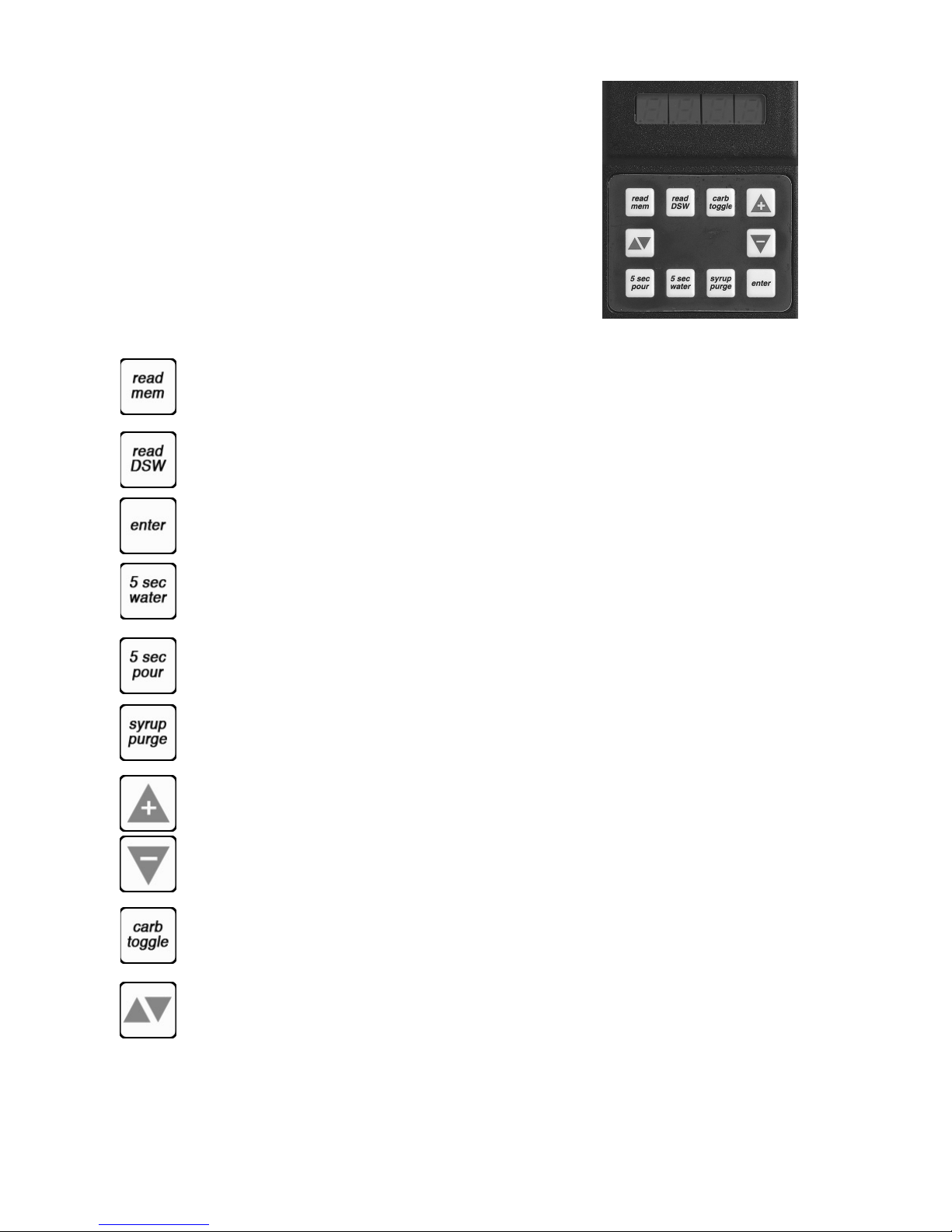
6. PROGRAMMER OPERATING PROCEDURES
FIGURE 8 - HANDHELD PROGRAMMER
6.1 CONNECTING
A. Remove the ID panel from the front of the valve.
B. Insert the programmer’s 10-pin connector into the ID
Panel plug on the front of the circuit board.
C. When properly connected, the programmer will run
a self diagnostic test. The display will show all “8”s
with the decimal points lighted.
After three (3) seconds, the display indicates the
setting of the dip switches.
D. If the programmer does not run its diagnostic test
properly, disconnect it and try plugging it in again. If
the programmer still fails, replace the programmer.
6.2 FUNCTIONS
Read Memory: Press to read and display the current settings programmed into the valve
memory (i.e., S/W revision, ratio, and carb/non carb settings).
Read Dip Switches: Press to read the dip switch settings. NOTE: Dip Swiches were used on
some eld test valves (refer to PN 28-0301, 12/20/95)
Write Memory: Press to write the programmer’s displayed ratio and carbonation settings into
the valve’s memory.
Timed 5 Second Water: Press to pour water for ve (5) seconds. The programmer will dis
play the ratio, the counts from the owmeter, the ow rate in oz/sec, and the ow rate in ml/
sec.
Timed 5 Second Pour: Press to dispense a ve (5) second pour of water and syrup for ratio
testing. When complete, the programmer displays the ratio, carbonation settings, and total
Flowmeter counts.
Syrup Purge: Press and release to dispense a six (6) second syrup purge. Continue holding
to purge syrup from system.
Ratio + (Plus): Pressing this button will increase the ratio number on the display.
Ratio - (Minus): Pressing this button will decrease the ratio number on the display.
Carb Toggle: Press to toggle the carbonation setting from carbonated “C” to non-carbonated
water “n”.
Pour/Stop: Press this button to manually pour a mixed drink. This button will also stop a
timed pour.
8
Page 9
6.3 SETTING THE RATIO/CARBONATION
A. Connect the programmer to the Valve.
B. Press the [Read Mem] button.
C. Press the [Ratio +] or the [Ratio -] key until the desired ratio is displayed.
D. Verify drink type. Press [Carb Toggle] to select [C] for carbonated or [n] for non-carbonated.
E. Press the [Enter] button to program the valve with the setting on the display
F. Verify Ratio by pressing [Read Mem].
G. Disconnect the programmer.
7.0 PORTION CONTROL PROGRAMMING PROCEDURES
The following procedures describe the operation and programming of portion control ID panels for the
Volumetric Valve.
7.1 OPERATION
A. Cup buttons are Small, Medium, Large, Extra-Large.
B. Press and release the desired cup size. Valve will ll cup as programmed (See below).
C. Pour/Cancel Button
1. Push and release to cancel or stop valve dispensing.
2. Push and hold for continuous pour.
D. Water Button
1. Push and hold for continuous water pour.
2. Valve will dispense carbonated or non-carbonated water, depending on its location on the
dispenser.
7.2 TEACH AND LEARN PORTION CONTROL PROGRAMMING
In this mode, the valve will record (learn) the steps to ll each cup size, including the top off
delay time. When activated, the valve dispenses the appropriate drink volume. If a top off has been
entered, the valve will pause for the programmed length of time. Finally, the valve will dispense the
correct top off amount.
A. Initial Install Procedure
1. Simultaneously, press and hold the small cup button and the extra-large cup button
switches on the portion control until the LED light in center of module starts blinking, then
release switches. The blinking LED indicates that the set mode is active.
2. Put desired amount of ice in cup, place cup under valve and push selected size button
(small, medium, large, or extra-large). Hold button in until cup lls to desired portion, then
release button.
3. Top off: If a top off is not needed, go to Step 4. Wait for foam to settle, then actuate button
again to top off. NOTE: Only one (1) top off is allowed.
4. Repeat steps 2 and 3 for other drink sizes. Go to Step 5 to exit program mode.
5. Press and release pour/stop button to return the portion control to the operational mode.
Blinking LED light will go out.
6. Repeat steps 1 through 5 for remaining valves.
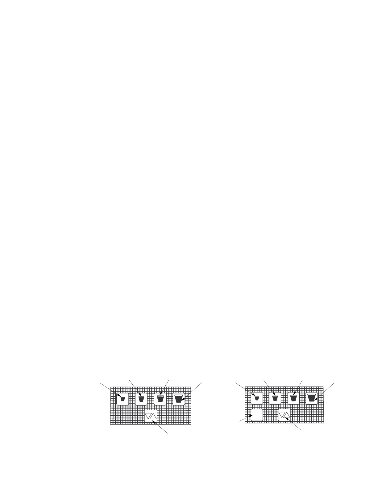
FIGURE 9 - PORTION CONTROL,
Small
Cup Button
Medium
Cup Button
7.3 TO CHANGE DISPENSE SIZE
Use procedures in the Initial Install Procedure discussed above; it is not necessary to reprogram
every size.
CUP BUTTONS
Cup Button
Pour/Stop
Cup Button
Large
Extra-Large
Cup Button
9
FIGURE 10 - PORTION CONTROL,
CUP BUTTONS,WITH WATER
Small
Cup Button
Water
Button
Medium
Cup Button
water
Large
Cup Button
Pour/Stop
Cup Button
Extra-Large
Cup Button
Page 10

7.4 CALIBRATED CUP PORTION CONTROL PROGRAMMING
In this mode, the valve adds the volume from each programming step to the total drink size. When
activated, the valve dispenses the total drink, without pauses.
A. Simultaneously, press and hold the small and large buttons (see Figures 9 and 10) on the
portion control until the LED light in the center starts blinking, then release switches.
B. Place volume cup under nozzle of valve to be calibrated.
C. Press appropriate size switch and ll volume cup to a point just short of the calibration mark on
the volume cup. The LED will stay lighted constantly while programming an individual cup size.
D. Let foam settle, jog size switch until liquid reaches the calibration mark on the volume cup.
E. Press pour/stop button to end programming for selected cup size. LED will start blinking.
F. To program another cup size, repeat steps B through E, this section (above).
G. To exit the calibrated cup programming mode, press the pour/stop button when the LED is
blinking. If the LED is lighted constantly, press the pour/stop button once to end the cup size
program (LED starts blinking) and again to exit the program mode (LED off).
8. COVER AND ID PANEL
8.1 REMOVAL
A. ID panel: Slide ID panel up until it detaches from cover.
CAUTION PULL CAREFULLY, IF WIRES FOR A PUSHBUTTON OR PORTION CONTROL ARE ATTACHED.
PRECAUCIÓN TIRE CUIDADOSAMENTE SI ESTÁN ADHERIDOS LOS CABLES A UN BOTÓN DE EMPUJE O UN
CONTROL DE PORCIÓN.
!
B. ID panel connector (If applicable): The circuit board connector on the Volumetric Valve has an
properly connected. The interlock feature consists of a recess in the circuit board connector
When removing the connector, it is important to hold the housing and not the wires. The
housing easily slides out of the circuit board connector by placing a very slight downward
pressure onto the housing as it is removed (see Figure 12).
NOTE: Pulling straight out while holding onto the wires is not recommended and will likely cause
C. Cover: Loosen, but do not remove, cover screw. Pull cover straight up, until it is clear of the
NOTE: Push Button ID panel or lever must be connected to run “Syrup Pour” test from dip
switches. Push Button ID panel or lever must be disconnected to use the hand held programmer.
ATTENTION SI L’ENSEMBLE EST RELIÉ PAR FILS À UN BOUTON-POUSSOIR DE COMMANDE OU À UNE
COMMANDE DE RÉGLAGE DE DÉBIT INDIVIDUEL, LE TIRER DÉLICATEMENT.
interlock feature that acts to keep an ID panel plug or Hand Held Programmer (HHP) plug
housing and a raised tab on the housing plug. See Figure 11, for the raised tab conguration.
damage to the valve, ID panel and/or HHP cable.
valve body.
FIGURE 11 FIGURE 12
Raised Tab,
Housing Plug
10
Slight downward pressure here,
while pulling housing straight out
PUSH
Page 11

8.2 INSTALLATION
Lever Arm
NOTE: Part Number in ( ) is a Coca-Cola PN
54-0125/01 Shown
(24234 Shown)
A. Plug the ID panel connector (if applicable) into the front of the circuit board.
B. Slide cover over valve, making certain that wires do not get pinched.
NOTE: If solenoids were replaced or moved, ensure terminal blocks do not interfere with cover.
Check for proper orientation.
C. Tighten cover screw.
CAUTION DO NOT PINCH OR DAMAGE ID PANEL WIRES DURING INSTALLATION.
PRECAUCIÓN NO PERFORE O DAÑE LOS CABLES DEL PÁNEL DURANTE LA INSTALACIÓN.
!
ATTENTION S’ASSURER DE NE PAS PINCER OU ENDOMMAGER LES FILS DU PANNEAU ÉLECTRIQUE
ID LORS DU MONTAGE.
D. Align the bottom of the ID panel with the guide slots on the front of the cover. Slide the ID panel
down into place.
NOTE: Attach the ID panel connector before installing cover to keep wires out of the way.
9. VALVE
9.1 REMOVAL FROM BACK BLOCK
FIGURE 13
I.D. Panel, Large Pushbutton
A. Remove cover and ID panel (see Section 8).
B. Turn back block shut-offs to the closed position.
C. Activate the valve (press lever arm or pushbutton) to
relieve pressure.
D. Unplug 24 Volt supply.
E. Raise valve retainer. NOTE: The retainer cannot be
pulled up until the back block shut-offs are properly
closed.
Valve with
Cover in Place
F. Pull the valve off of the back block.
9.2 MOUNTING ON BACK BLOCK
A. Check o-rings on back block. Replace o-rings, if
necessary.
B. Apply 111 Lubricant to o-rings, if necessary.
C. Press valve into the back block.
D. Lower the valve retainer to lock the valve in place.
E. Turn the back block shut-offs to the open position.
F. Connect the 24 Volt supply to the plug on the circuit
board.
G. Install cover and ID panel.
FIGURE 14
10. LEVER ARM
10.1 REMOVAL
A. Remove cover and ID panel (see Section 8).
B. Remove valve from back block (see Section 9).
C. Insert lever arm into bottom plate and snap
pivot axle into back of valve as shown in
Figure 14.
10.2 INSTALLATION
A. With the valve detached from the back block,
insert the magnet end of the lever arm into the
hole on the bottom, backside of the valve.
B. Pull the lever arm back while pushing it into the valve, so the pivot axle can be positioned over
the slot formed by the valve body and bottom plate. Release the valve to allow the pivot axle to
be seated in the slot.
C. Mount valve in back block.
D. Install ID panel and cover.
11
Page 12

NOTE: Part Number in ( ) is a Coca-Cola PN
11. NOZZLE/DIFFUSER
11.1 REMOVAL
A. Remove nozzle, by twisting it counter-clockwise and
pulling it in a downward direction (see Figure 15).
B. Remove the diffuser assembly, by pulling it in a
downward direction.
11.2 ASSEMBLY
A. Slide o-ring into the groove on the end of the diffuser
assembly, if necessary.
B. Apply 111 Lubricant to o-ring, as required.
C. Insert diffuser assembly carefully into the underside of
the valve.
D. Install nozzle by inserting it into the bottom plate and
twisting it in a clockwise direction to lock it into place.
12. CIRCUIT BOARD
12.1 REMOVAL
A. Unplug 24 Volt supply.
B. Use a at end screw driver to remove each of the
screws holding the circuit board in place.
C. Disconnect the solenoids and owmeter from the
circuit board, by pressing each connectors locking tab
and pulling it down out of its socket.
D. Lift the circuit board off of the valve.
12.2 INSTALLATION
A. Plug the connector from the rear syrup
solenoid into the receptacle on the underside of
the circuit board near the rear of the valve.
B. Plug the connector from the soda solenoid into
the receptacle located at the front, left corner of
the circuit board.
NOTE: Each solenoid plugs into the nearest circuit
board socket.
C. Plug the connector from the front syrup
solenoid into the receptacle between the soda
solenoid connector and the 10-pin connector
on the front of the circuit board.
D. Plug the 4-pin connector from the owmeter
in the 4-pin receptacle near the front corner of
the circuit board.
E. Position circuit board on the mounting posts on
top of the syrup body 10-pin connector to the
front.
F. Secure circuit board with two (2) screws.
G. Connect 24 Volt supply.
FIGURE 15
Diffuser Assembly
54-0176/04
(24245)
Nozzle
05-2053/01
(24246)
FIGURE 16
Programmer Plug, ID Panel
Front Syrup Solenoid
Plug, Rear Syrup Solenoid
Plug, Flowmeter
Plug, Water Solenoid
12
Page 13

13. FLOWMETER
Circuit Board
13.1 REMOVAL
A. Remove cover and ID panel (see Cover and
ID Panel, Section 8).
B. Remove valve from back block (see Valve,
Section 9).
C. Remove nozzle/diffuser (see Nozzle/ Diffuser,
Section 11).
D. Remove lever arm, if applicable (see Lever Arm, Section 10).
E. Remove four (4) screws holding the bottom plate in place.
F. Pull bottom plate off.
CAUTION USE CARE WHEN REMOVING THE SCREWS TO AVOID
DAMAGING THE FLOWMETER SENSOR WIRES.
PRECAUCIÓN TENGA CUIDADO CUANDO RETIRE LOS TORNILLOS
PARA EVITAR DAÑAR LOS CABLES DEL SENSOR DEL FLUXÓMETRO.
!
G. Remove four (4) screws holding the owmeter body in place.
H. Carefully pull the owmeter body and o-ring off of the valve.
owmeter body as ball bearings are snapped into place.
ATTENTION LORSQU’IL S’AGIRA DE DÉPOSER LES VIS, IL
CONVIENDRA DE PRENDRE SOIN DE NE PAS ENDOMMAGER LES FILS
DU CAPTEUR DUDÉBITMÈTRE.
Use caution to not pull the rotor and bearings out of the
Screw
04-0640
(24208)
FIGURE 17
52-2345/05
(24155)
13.2 INSTALLATION
A. Place the o-ring in the groove in the owmeter body.
CAUTION DO NOT PINCH THE FLOWMETER O-RING DURING INSTALLATION. THE O-RING MUST STAY IN THE
GROOVE ON THE FLOWMETER BODY.
PRECAUCIÓN NO PELLIZQUE EL ANILLO O- DEL FLUXÓMETRO DURANTE LA INSTALACIÓN. EL ANILLO
O- DEBE MANTENERSE EN LA RANURA SOBRE EL CUERPO DEL FLUXÓMETRO.
!
ATTENTION FAIRE ATTENTION DE NE PAS PINCER LE JOINT TORIQUE DU DÉBITMÈTRE LORS DU MONTAGE.
LE JOINT TORIQUE DEVRA RESTER LOGÉ DANS LA RAINURE PRÉVUE SUR LE CORPS DU DÉBITMÈTRE.
B. If necessary, carefully apply a small amount of 111 Lubricant to o-ring. NOTE: Do not get
lubricant in the owmeter.
C. With the wires exiting toward the front of the valve, carefully press the owmeter sub-assembly
into place on the underside of the valve body. The at surface of the owmeter must be ush
against the mounting surface of the valve body.
D. Install four (4) screws to hold the owmeter in place. Gently position the sensor wires so they
are not pinched or scraped when the screws are installed. NOTE: The owmeter screws are
5/8” long, and are longer than the bottom plate screws.
E. Thread the connector attached to the owmeter sensor wires through hole on the valve body
that is in front of ow washer mounting port (see Figure 18).
F. Place the owmeter sensor wires around the outside of the ow washer mounting port, so that
they will not interfere with the bottom plate installation.
CAUTION DO NOT PINCH ANY WIRES WITH THE BOTTOM PLATE.
PRECAUCIÓN NO PELLIZQUE NINGÚN CABLE CON EL FONDO.
!
G. Line up holes on the bottom plate with the screw holes on the underside of the valve body. The
H. Secure bottom plate in place with four (4) screws.
I. Replace nozzle/diffuser and lever arm (if applicable).
J. Install ID panel and cover.
ATTENTION VEILLER À CE QUE L’EMBASE NE VIENNE PAS PINCER LES FILS.
raised sections around the screw holes should t completely in the counterbores on the bottom
plate.
13
Page 14

14. FLOW WASHER ASSEMBLY
NOTE: Part Number in ( ) is a Coca-Cola PN
Thread Flowmeter wires though
14.1 REMOVAL
A. Remove cover and ID panel (see Cover and ID Panel, Section 8).
B. Remove valve from back block (see Valve, Section 9).
C. Remove nozzle/diffuser (see Nozzle/ Diffuser, Section 11).
D. Remove lever arm, if applicable (see Lever Arm, Section 10).
E. Remove four (4) screws holding the bottom plate in place.
F. Pull bottom plate off.
G. Pull the ow washer assembly out of its port, next to the nozzle mount on the underside of the
valve. The ow washer assembly will be one of the following:
1. Gray, 3.0 ounce/sec product ow.
FIGURE 18 - FLOW WASHER/SYRUP PLUG ACCESS
2. White, 2.25 ounce/sec product ow.
3. Red, 1.5 ounce/sec product ow.
Valve Body at this point.
14.2 INSTALLATION
A. Install o-rings, if necessary.
B. Apply 111 Lubricant to the o-rings, if necessary.
C. Install the appropriate ow washer assembly
into the keyed port on the underside of the
valve body.
NOTE: The ow washer has a at side and a
concave side. The ow washer must be installed
with the concave side facing the small diameter
hole in the ow washer retainer.
D. Place the owmeter wires around the outside of
the ow washer mounting port, so that they will
not interfere with the bottom plate installation.
E. Line up holes on the bottom plate with the
screw holes on the underside of the valve body.
The raised sections around the screw holes
should t completely in the counterbores on the
bottom plate.
CAUTION DO NOT PINCH ANY WIRES DURING INSTALL
PRECAUCIÓN NO NO PELLIZQUE NINGÚN CABLE
DURANTE LA INSTALACIÓN.
!
ATTENTION VEILLER À NE COINCER AUCUN FIL LORS
DU MONTAGE.
F. Secure bottom plate in place with four (4)
screws.
G. Mount valve in back block.
H. Replace nozzle/diffuser and lever arm (if
O-Ring
02-0003
(10049)
Regulator Plug
(some models)
05-0779/01
(24236)
Flow Washer Assy
54-0192 (Red)
(24237)
Flow Washer Assy
54-0193 (White)
(24238)
Flow Washer Assy
54-0194 (Gray)
(24239)
Bottom Plate
05-0960/01
(24244)
Screw
04-0633/01
(24209)
O-Ring
02-0005
(10050)
Diffuser Assembly
54-0176/04
(24245)
Nozzle
05-2053/01
(24246)
applicable).
I. Install ID panel and cover.
15. SYRUP REGULATOR
15.1 REMOVAL
A. If the syrup regulator plug or its o-rings need to be replaced, remove the valve from the back
block and take off the bottom plate.
B. Pull the regulator plug from the regulator port near the back of the underside of the valve body.
NOTE: There is nothing mounted inside the regulator port.
14
Page 15

NOTE: Part Number in ( ) is a Coca-Cola PN
15.2 INSTALLATION
A. Install o-rings in groove on regulator plug.
B. Apply 111 Lubricant to the o-ring.
C. Insert regulator plug into keyed hole on the
underside of the valve body.
D. Place the owmeter wires around the outside
of the ow washer assembly, so that they will
!
not interfere with the bottom plate installation.
CAUTION DO NOT PINCH ANY WIRES DURING INSTALL
PRECAUCIÓN NO NO PELLIZQUE NINGÚN CABLE
DURANTE LA INSTALACIÓN.
ATTENTION VEILLER À NE COINCER AUCUN FIL LORS
DU MONTAGE.
Thread
Flowmeter
wires though
Valve Body
at this point
Flowmeter
O-Ring
02-0354
E. Line up holes on the bottom plate with the
Flowmeter
Body
54-0126/01
Bottom Plate
05-0960/01
(24244)
!
screw holes on the underside of the valve body.
CAUTION BOTTOM PLATE HOLDS THE REGULATOR
PLUG AND THE FLOW WASHER RETAINER IN PLACE.
DO NOT PRESSURIZE UNTIL BOTTOM PLATE IS FIRMLY
ATTACHED.
PRECAUCIÓN LA PLACA INFERIOR SOSTIENE LA
CLAVIJA DEL REGULADOR Y LA ARANDELA DE
RETENCIÓN DEL FLUJO EN SU LUGAR. NO LA
PRESIONE HASTA QUE LA PLACA INFERIOR SE HAYA
COLOCADO FIRMEMENTE.
ATTENTION L’EMBASE MAINTIENT LE CLAPET DU
RÉGULA-TEUR AINSI QUE LE COLLIER DE RETENUE DU
RÉDUCTEUR DE PRESSION EN PLACE. NE PAS METTRE
SOUS PRESSION AVANT QUE L’EMBASE NE SOIT
SOLIDEMENT FIXÉE.
F. Secure bottom plate in place with four (4)
screws.
G. Mount valve on back block.
H. Replace nozzle/diffuser and lever arm (if
applicable).
I. Install ID panel and cover.
16. WATER SOLENOID ACCESS
16.1 REMOVAL
A. Disconnect valve from back block (see Valve,
Section 9).
B. Remove circuit board (see Circuit Board, Section 12).
FIGURE 19 - FLOWMETER ACCESS
Screw
04-0549
(24242)
Screw
04-0633/01
(24209)
O-Ring
02-0005
(10050)
Diffuser Assembly
54-0176/04
(24245)
Nozzle
05-2053/01
(24246)
CAUTION AVOID DAMAGING OR DROPPING THE SOLENOID OR COMPONENTS WHEN THE RETAINER IS
REMOVE.
PRECAUCIÓN EVITE DAÑAR O TIRAR EL SOLENOIDE O LOS COMPONENTES CUANDO RETIRE EL
RETENEDOR.
!
ATTENTION ÉVITER D’ENDOMMAGER OU DE FAIRE TOMBER L’ÉLECTROVANNE OU AUTRES COMPOSANTS
LORSQUE.
C. Remove three (3) screws holding the water solenoid retainer in place. Remove the retainer.
D. Take the water solenoid assembly out of the valve.
15
Page 16

16.2 INSTALLATION
If a water seat is already installed, skip to Step H.
A. Put o-ring in groove on water seat.
CAUTION USE CARE TO NOT DAMAGE SEATING AREA WHILE INSERTING WATER SEAT INTO VALVE BODY.
PRECAUCIÓN TENGA CUIDADO DE NO DAÑAR EL ÁREA DE ASIENTO MIENTRAS QUE INSERTA EL ASIENTO
DE AGUA DENTRO DEL CUERPO DE LA VÁLVULA.
!
B. Apply 111 Lubricant to outside edges of o-ring.
C. Carefully press water seat into the hole at the base of the water solenoid mounting area in the
D. If necessary, install ow washer (See Flow Washer Assembly, Section 14).
!
E. Place the owmeter wires around the outside of the ow washer assembly, so that they will not
F. Secure bottom plate in place with four (4) Screws.
G. Apply 111 Lubricant to the outside edge of o-ring on the water solenoid sub-assembly.
!
H. Turn valve body over and insert water solenoid sub-assembly into the hole where the water
I. Place the water solenoid retainer on top of the solenoid and install three (3) screws. The water
J. Install the circuit board.
K. Reconnect the valve.
ATTENTION VEILLER À NE PAS ENDOMMAGER LA ZONE D’ÉTANCHÉITÉ À L’EAU LORS DE L’INSERTION DU
SIÈGE DANS LE CORPS DE LA VANNE.
valve body. Make certain that the water seat remains completely inserted into the hole. Apply
more lubricant to the o-ring, if necessary,
CAUTION DO NOT PINCH ANY WIRES DURING INSTALL
PRECAUCIÓN NO NO PELLIZQUE NINGÚN CABLE DURANTE LA INSTALACIÓN.
ATTENTION VEILLER À NE COINCER AUCUN FIL LORS DU MONTAGE.
interfere with the bottom plate installation.
CAUTION DO NOT GET LUBRICANT ON THE SPRING OR CORE IN THE SOLENOID.
PRECAUCIÓN NO PERMITA QUE EL LUBRICANTE SE INTRODUZCA EN EL RESORTE O EN EL CORAZÓN DEL
SOLENOIDE.
ATTENTION FAIRE ATTENTION DE NE PAS RÉPANDRE DE LA GRAISSE SUR LE RESSORT OU LE
NOYEAU-PLONGEUR DE L’ÉLECTRO-AIMANT.
seat is mounted. Carefully twist the solenoid while pressing it into place, so that the o-ring does
not get pinched. The terminal block on the side of the solenoid must be on the outside edge of
the valve body, turned so that it touches the single solenoid retainer post towards the front of
the valve. Hold the solenoid in place until the retainer is rmly mounted.
solenoid sub-assembly must remain rmly seated during installation to avoid damaging the
o-ring. Tighten each screw a little at a time, so that the retainer stays perpendicular to the water
solenoid.
16
Page 17

17. WATER SOLENOID ASSEMBLY
Screw
NOTE: Part Number in ( ) is a Coca-Cola PN
17.1 DISASSEMBLY
A. Remove the core/spring assembly from the solenoid.
B. Slide the o-ring off the end of the solenoid.
C. Lift the solenoid washer off the end of the solenoid.
CAUTION THE PLUG NUT MAY PULL OUT OF THE COIL, WHEN TRYING TO LOOSEN. THE COIL CAN BE
DAMAGED IF DROPPED.
PRECAUCIÓN LA TUERCA DE LA CLAVIJA PUEDE ZAFARSE DE LA BOBINA, CUANDO SE TRATA DE
AFLOJARLA. SI SE CAE LA BOBINA SE PUEDE DAÑAR.
!
ATTENTION IL SERA POSSIBLE QUE L’ÉCROU DE BLOCAGE DE LA BOBINE SE DÉSOLIDARISE DE CETTE
DERNIÈRE LORS DU DESSERRAGE DE L’ENSEMBLE. VEILLER À NE PAS FAIRE TOMBER LA BOBINE, AU RISQUE
DE L’ENDOMMAGER.
D. Carefully hold the wire terminal block on the side of the coil while pulling the solenoid bonnet
to loosen the water plug nut. When the water plug nut has been pulled out of the coil enough,
remove it and the bonnet by hand.
17.2 ASSEMBLY
A. Slide o-ring into the groove on the water plug nut.
B. Slide bonnet over coil.
C. Apply 111 Lubricant to o-ring in plug nut.
D. Press plug nut into top of coil/bonnet assembly.
E. Place solenoid washer on bottom end of the coil/bonnet assembly.
F. Place o-ring over end of coil extending through the solenoid washer.
G. Insert core/spring assembly into the end of the solenoid assembly.
NOTE: Water and syrup solenoid coils are interchangeable.
FIGURE 20 -WATER SOLENOID ACCESS FIGURE 21 - WATER SOLENOID ASSEMBLY
04-0640
(24208)
Circuit Board
64-5040
(24155)
Plug Nut
10-0868
O-Ring
02-0538
(10061)
Screw
04-0637
(24221)
Solenoid
Retainer
05-0707
(24222)
Water
Solenoid
Assembly
Soda Seat
05-0706
(24233)
O-Ring
02-0005
(10050)
Bonnet,
Solenoid
81-0404/01
(24224)
Coil
12-0132/04-01
(24225)
Washer,
Solenoid
04-0820/01
(24226)
O-Ring
02-0109
(17428)
Core/Spring
Assembly
82-1624/03
(24229)
NOTE: Part Number in ( ) is a Coca-Cola PN
17
Page 18
18. SYRUP BODY ACCESS
18.1 REMOVAL
A. Remove valve from back block (see Valve, Section 9).
B. Remove circuit board (see Circuit Board, Section 12).
C. Remove nozzle/diffuser (see Nozzle/Diffuser, Section 11).
D. Remove lever arm, if applicable (see Lever Arm, Section 10).
E. Remove four (4) screws holding the bottom plate in place.
F. Pull bottom plate off.
G. Remove two (2) screws located at front and rear of syrup body.
H. Turn valve assembly over and remove the two (2) screws on the underside of the main body,
holding the syrup body in place.
CAUTION PARTS OF THE SYRUP SOLENOIDS MAY FALL OUT WHEN THE SYRUP BODY IS REMOVED.
PRECAUCIÓN PARTES DE LOS SOLENOIDES DEL JARABE SE PUEDEN CAER CUANDO SE RETIRA EL
CUERPO DEL JARABE.
!
I. Lift the syrup body subassembly off of the syrup solenoids.
J. Pull the syrup down tube restrictor assembly out of the port on the side of the syrup body.
18.2 INSTALLATION
A. If necessary, install an o-ring on either end of the syrup down tube restrictor assembly.
B. Apply 111 Lubricant around each end of the syrup down tube restrictor, if necessary.
C. Insert syrup down tube restrictor assembly into port on the side of the syrup body
sub-assembly.
D. Apply 111 Lubricant to the outside edge of o-ring on the syrup solenoids.
ATTENTION CERTAINS COMPOSANTS DES ÉLECTRO-AIMANTS DU CÔTÉ SIROP POURRONT TOMBER
LORSQUE LE CORPS DE LA VANNE SERA DÉPOSÉ.
CAUTION DO NOT GET LUBRICANT ON THE SPRING OR CORE IN THE SOLENOID.
PRECAUCIÓN NO PERMITA QUE EL LUBRICANTE SE INTRODUZCA EN EL RESORTE O EN EL CORAZÓN DEL
SOLENOIDE.
!
E. Rotate the front syrup solenoid until its terminal block rests in groove, towards the syrup down
F. Rotate the back syrup solenoid, so that its terminal block rests against the water solenoid
retainer mount.
ATTENTION FAIRE ATTENTION DE NE PAS RÉPANDRE DE LA GRAISSE SUR LE RESSORT OU LE NOYEAU-
PLONGEUR DE L’ÉLECTRO-AIMANT.
tube port.
CAUTION SYRUP SOLENOIDS MUST BE SEATED AGAINST MAIN BODY. IF SOLENOIDS BECOME UNSEATED,
SEE SYRUP SOLENOID ACCESS, INSTALLATION, SECTION 19.
PRECAUCIÓN LOS SOLENOIDES DEL JARABE DEBEN ESTAR ASENTADOS CONTRA EL CUERPO PRINCIPAL.
SI LOS SOLENOIDES NO ESTÁN ASENTADOS, VEA EN LA SECCIÓN 19 DE LA INSTALACIÓN EL ACCESO A LOS
SOLENOIDES DE
!
ATTENTION LES ÉLECTRO-AIMANTS DU CÔTÉ SIROP DEVRONT RESTER PLAQUÉS CONTRE LE CORPS
PRINCIPAL. SI LES ÉLECTRO-AIMANTS SORTENT DE LEUR SIÈGE, CONSULTEZ LES INSTRUCTIONS RELATIVES
À LEUR ACCÈS ET MONTAGE CONTENUES DANS LA SECTION 19.
G. Carefully press the syrup body sub-assembly into place on top of the syrup solenoids. If the
syrup body will not smoothly press into place, then apply more 111 Lubricant to the solenoid
o-rings, so that they will not be pinched.
1. Make certain the syrup down tube restrictor assembly goes into the down tube port on the
valve body.
2. Hold the syrup body rmly in place until the mounting screws are completely installed.
NOTE: Mounting screws must be tight. Loose screws will cause leaks and alter valve
performance.
H. Install screw at front and rear of syrup body.
18
Page 19

18.2 SYRUP BODY INSTALLATION - CONTINUED
Screw
I. Install two (2) screws on the underside of the main body, to secure syrup body.
J. Install circuit board (see Circuit Board, Section 12) and secure with two (2) screws.
K. Place the owmeter wires around the outside of the ow washer assembly, so that they will not
interfere with the bottom plate installation. Connect to circuit board.
CAUTION DO NOT PINCH ANY WIRES DURING INSTALL
PRECAUCIÓN NO NO PELLIZQUE NINGÚN CABLE DURANTE LA INSTALACIÓN.
!
ATTENTION VEILLER À NE COINCER AUCUN FIL LORS DU MONTAGE.
L. Line up holes on the bottom plate with the screw holes on the underside of the valve body.
M. Secure bottom plate with four (4) screws.
N. Install nozzle/diffuser
O. Install lever arm, if applicable.
FIGURE 22 - SYRUP BODY ACCESS
Circuit Board
64-5040
(24155)
Syrup Body
Subassembly
82-1117/02
(24217)
Down Tube
Restrictor
Assembly
54-0190
(24220)
04-0640
(24208)
Screw
04-0549
(24242)
19
Bottom Plate
05-0960/01
(24244)
Screw
04-0633/01
(24209)
O-Ring
02-0005
(10050)
Diffuser
Assembly
54-0176/04
(24245)
Nozzle
05-2053/01
(24246)
Screw
04-0637
(24221)
Page 20

19. SYRUP SOLENOID ACCESS
O-Ring
Bottom Plate
Screw
Syrup
Syrup Down Tube
Syrup Body
Screw
Screw
Circuit Board
Nozzle
Diffuser
Screw
O-Ring
05-2053/01
(24246)
Assembly
54-0176/04
(24245)
02-0005
(10050)
04-0637
(24221)
04-0633/01
(24209)
02-0005
(10050)
05-0960/01
(24244)
Restrictor Assembly
54-0190
(24220)
Subassembly
82-1117/02
(24217)
Solenoid
Subassembly
04-0459
(24242)
64-5040
04-0640
(24208)
(24155)
19.1 REMOVAL
A. Remove valve from back block (see Valve,
B. Remove circuit board (see Circuit Board,
Section 12).
C. Remove nozzle/diffuser (see Nozzle/ Diffuser,
D. Remove lever arm, if applicable (see Lever
E. Remove four (4) screws holding the bottom
F. Pull bottom plate off.
G. Remove the two (2) screws that hold the syrup
H. Turn valve assembly over and remove the two
I. Lift the syrup body off of the syrup solenoids.
!
J. Lift each syrup solenoid out of the valve.
NOTE: The o-ring mounted under neath the
solenoid may stick to the solenoid when it is
removed.
19.2 INSTALLATION
A. Install an o-ring over the port in the bottom of
B. Apply 111 Lubricant to the outside edges of the
C. Insert syrup solenoid sub-assembly into the rear mounting area on the main body. Twist the
D. Insert syrup solenoid sub-assembly into the front mounting area on the main body. Twist the
E. Apply 111 Lubricant around each of the o-rings on the syrup down tube.
FIGURE 23 - SYRUP SOLENOID ACCESS
Section 9).
Section 11).
Arm, Section 10).
plate in place.
body in place.
(2) screws, on the underside of the main body,
holding the syrup body in place.
CAUTION PARTS OF THE SYRUP SOLENOIDS MAY
FALL OUT WHEN THE SYRUP BODY IS REMOVED.
PRECAUCIÓN PARTES DE LOS SOLENOIDES DEL
JARABE SE PUEDEN CAER CUANDO SE RETIRA EL
CUERPO DEL JARABE.
ATTENTION CERTAINS COMPOSANTS DES
ÉLECTRO-AIMANTS DU CÔTÉ SIROP POURRONT
TOMBER LORSQUE LE CORPS DE LA VANNE SERA
DÉPOSÉ.
each syrup solenoid mounting area on the
main body. Ensure that o-ring seats to bottom
of mounting port.
o-rings.
solenoid while pushing it into place to avoid pinching the o-ring at the bottom of the mounting
area. Turn the solenoid, so that the terminal block rests against the water solenoid retainer
post.
solenoid while pushing it into place to avoid pinching the o-ring at the bottom of the mounting
area. Turn the solenoid so that the terminal block rests in groove towards, but not over, the
syrup down tube port.
!
CAUTION DO NOT GET LUBRICANT ON THE SPRING OR CORE IN THE SOLENOID.
PRECAUCIÓN NO PERMITA QUE EL LUBRICANTE SE INTRODUZCA EN EL RESORTE O EN EL CORAZÓN DEL
SOLENOIDE.
ATTENTION FAIRE ATTENTION DE NE PAS RÉPANDRE DE LA GRAISSE SUR LE RESSORT OU LE NOYEAU-
PLONGEUR DE L’ÉLECTRO-AIMANT.
20
Page 21

O-Ring
Plug Nut
O-Ring
Solenoid
Coil
O-Ring
Core/Spring
Solenoid
02-0005
(10050)
10-0280/04
(24230)
02-0538
(10061)
Bonnet
81-0407/01
(24224)
Washer
04-0820/01
(24226)
12-0132/04-01
(24225)
Assembly
82-1624/03
(24229)
02-0109
(17428)
19.2 SYRUP SOLENOID INSTALLATION - CONTINUED
F. Insert syrup down tube into port on the side of the syrup body sub-assembly.
G. Apply 111 Lubricant to the outside edge of o-ring on the syrup solenoids.
H. Carefully press the syrup body sub-assembly into place on top of the syrup solenoids. If the
syrup body will not smoothly press into place, then apply more 111 Lubricant to the solenoid
o-rings, so that they will not be pinched. Make certain the syrup down tube goes into the down
tube port on the valve body. If the solenoid assembly becomes unseated, remove solenoid
assembly and repeat Steps A through D above. Hold the syrup body rmly in place until the
mounting screws are completely installed.
I. Install two (2) upper screws located at front and rear of syrup body.
J. Install two (2) screws on the underside of main body, to secure the syrup body.
K. Place the owmeter wires around the outside of the ow washer assembly, so that they will not
interfere with the bottom plate installation.
CAUTION DO NOT PINCH ANY WIRES DURING INSTALL
PRECAUCIÓN NO NO PELLIZQUE NINGÚN CABLE DURANTE LA INSTALACIÓN.
!
L. Line up holes on the bottom plate with the screw
ATTENTION VEILLER À NE COINCER AUCUN FIL LORS DU MONTAGE.
FIGURE 24 - SYRUP SOLENOID ASSEMBLY
holes on the underside of the main body.
M. Secure bottom plate in place with four (4) screws.
N. Install nozzle/diffuser
O. Install lever arm, if applicable.
P. Install circuit board (see Circuit Board, Section 12).
20. SYRUP SOLENOID ASSEMBLY
20.1 DISASSEMBLY
A. Remove the core/spring assembly from the solenoid.
B. Slide the o-ring off the end of the solenoid.
C. Lift the solenoid washer off the end of the solenoid.
D. If the o-ring remains in the end of the syrup plug nut or
on the post inside the syrup solenoid mounting area on
the main body, remove it.
CAUTION THE PLUG NUT MAY PULL OUT OF THE COIL, WHEN
TRYING TO LOOSEN. THE COIL CAN BE DAMAGED IF DROPPED.
PRECAUCIÓN LA TUERCA DE LA CLAVIJA PUEDE ZAFARSE DE
LA BOBINA, CUANDO SE TRATA DE AFLOJARLA. SI SE CAE LA
BOBINA SE PUEDE DAÑAR,
!
ATTENTION IL SERA POSSIBLE QUE L’ÉCROU DE BLOCAGE
DE LA BOBINE SE DÉSOLIDARISE DE CETTE DERNIÈRE LORS
DU DESSERRAGE DE L’ENSEMBLE. VEILLER À NE PAS FAIRE
TOMBER LA BOBINE, AU RISQUE DE L’ENDOMMAGER.
E. Carefully hold the wire terminal block on the side of the
coil while pulling the solenoid bonnet to loosen the
syrup plug nut. When the syrup plug nut has been
pulled out of the coil enough, remove it and the bonnet
by hand.
20.2 ASSEMBLY
A. Slide o-ring into the groove on the syrup plug nut.
B. Slide bonnet over coil.
C. Apply 111 Lubricant to o-ring in plug nut, then press plug nut into top of coil/bonnet assembly.
D. Place solenoid washer on bottom end of coil/bonnet assembly.
E. Place o-ring over end of coil extending through solenoid washer.
F. Insert the core/spring assembly into the end of the solenoid assembly.
NOTE: Water and syrup solenoid coils are interchangeable.
21
Page 22

21. TROUBLESHOOTING
SYMPTOM POSSIBLE CAUSE VERIFICATION SOLUTION
Drink Ratio Incorrect
(Weak or Strong);
Programmer available
A. Syrup restrictor
incorrectly set.
A. Check location of restrictor.
Restrictor must be in and up for diet bag-
in-box (BIB) applications, directly above
A. Position restrictor correctly.
theletter ‘D’ in the syrup down tube
assembly. Restrictor must be down and
out for non-diet drinks, directly below the
letter “S” in the syrup down tube
assembly.
Drink Ratio Incorrect
Weak or Strong);
Programmer
unavailable
B. Flow washer bad
(if installed).
C. Insufcient syrup
pressure.
D. Syrup obstructed.
E. Incorrect ratio
setting in memory.
F. Flowmeter
malfunctioning.
A. Syrup restrictor
incorrectly set.
B. Water ow over 2.7 oz/sec on a timed
pour.
C. Run syrup purge test on hand held
programmer. Output syrup should be
approx. 3 oz.
D. Incorrect ratio measurement after
circuit board replaced.
E1. Plug in programmer and press ‘Read
Memory’, and ratio and/ or carbonation
setting incorrect.
E2. Reprogramming of ratio and/or
carbonation setting does not work.
F. All other items above checked.
A. Check location of restrictor.
Restrictor must be in and up for diet
bag-in-box (BIB) applications, directly
above the letter “D” in the syrup down
tube assembly.
B. Replace ow washer assembly, or
install one if needed.
C. Increase dispensing system syrup
pressure.
D. Disassemble syrup side and
remove obstruction.
E1. Reprogram valve’s memory by
using “+/- keys, Carb Toggle and
‘Write Memory’.
E2. Replace circuit board.
F. Replace owmeter assembly
A. Position restrictor correctly.
B. Flow washer bad
(if installed)
C. Insufcient syrup
pressure.
D. Syrup obstructed.
side and remove
obstruction.
E. Flowmeter
malfunctioning
B. Water ow over 2.7oz/sec on a timed
pour. Flow washer installed correctly.
C. Run syrup purge test on hand held
programmer. Output syrup should be
approx. 3 oz.
D. Incorrect ratio measurement after
circuit board replaced.
E. All other items above checked.
22
B. Replace ow washer assembly,
or install one if needed.
C. Increase dispensing system syrup
pressure.
D. Disassemble syrup side and remove obstruction.
E. Replace owmeter assembly.
Page 23

SYMPTOM POSSIBLE CAUSE VERIFICATION SOLUTION
Nothing Dispenses
When Valve Activated
A. Circuit Board
malfunctioning
A. Programmer does not light up 24 volt
supply connected. NOTE: For Valves
A. Check fuser, or replace circuit
board.
made on/after Nov 2011, the amber
(orange) LED does not light up AND the
24 VOLT supply is connected.
Valve Dispenses
Water Only
B. Soda & front
syrup solenoid wires
plugged into wrong
connector.
C. Water solenoid
malfunctioning.
D.Water Solenoid
Core defective
E. Circuit board
malfunctioning.
F. Circuit board
misaligned. Lever not
making contact with
circuit board sensor.
A. Syrup shut-off on
back block is closed.
B. Out of syrup.
C, Syrup solenoid
unplugged.
D. Flowmeter
unplugged.
E. Flowmeter
connector wet.
F. Circuit board
malfunctioning.
G. Flowmeter rotor
obstructed, does not
turn freely.
H. Bad Flowmeter
Sensor.
I. Bad Syrup Solenoid.
J. Syrup solenoid core
is defective.
K. Syrup side of valve
obstructed.
B. ‘5 sec water’ button on programmer
dispenses small amount of syrup. Green
and red LEDs light up.
C. Programmer lights up, but does not
dispense water with ‘5 sec water’. Shutoffs are open. Green LED lights up.
D. Rubber poppet in core is swollen or
deformed. Green LED lights up.
E. New ratio cannot be entered w/
programmer.
F. Circuit board not screwed all the way
down. Board misaligned with holes and
mounting posts.
A. Coils click when activated by
programmer ‘syrup purge’. Green & Red
LEDs light up.
B. Syrup purge draws no syrup &
shut-off is open.
C. No clicking sound when ‘syrup purge’
activated.
D. Flow rates (0) after programmer ‘5
sec water’ pour. Green LED lights up.
E. Flow rate zero (0) after programmer
‘5 sec water’ pour. Circuit board wet. No
LEDs light up.
F. Programmer does not light up when
plugged in.
G. Flow rate zero (0) after programmer
‘5 sec water’ pour.
H. Flow rate zero (0) after programmer ‘5
sec water’ pour. Green LED lights up.
I. No clicking sound when ‘syrup purge’
activated & coils properly connected.
Green & Red LEDs light up.
J. Rubber poppet in core is swollen or
deformed.
K. Coils click when “syrup purge’
activated, shut-off is open, and syrup
supply is full. Green & Red LEDs light
up.
B. Connect soda and front syrup to
correct connectors.
C. Replace water solenoid.
D. Replace core.
E. Replace circuit board.
F. Ensure board is aligned & screw in
board all the way down.
A. Open syrup shut-off on mounting
block.
B. Replace BIB or nal.
C. Plug in syrup solenoid.
D. Plug in owmeter connector.
E. Unplug. Dry connector. Shake
water out of plug.
F. Replace circuit board.
G. Remove obstruction or replace
owmeter.
H. Replace owmeter assembly.
I. Replace syrup solenoid.
J. Replace core.
K. Disassemble syrup side &
remove obstruction.
23
Page 24

SYMPTOM POSSIBLE CAUSE VERIFICATION SOLUTION
Valve Dispenses
without Prompt/
A. Lever arm or lever
spring damaged.
A. Top end of lever arm does not return
to back of valve.
A. Replace lever arm and/or lever
spring.
Request
B. Push Button/
Portion Control
malfunctioning.
B. Valve stops, when panel unplugged
from circuit board.
B. Replace panel.
C. Replace circuit board.
C. Valve pours with lever arm retracted,
C. Circuit Board
malfunctioning.
or pushbutton/portion control unplugged.
D. Unplug. Dry out connector.
Shakewater out of plug.
D. Circuit board covered with water
D. Moisture in plug
(pushbutton
programmer) on front
of circuit card.
Valve Pours
A. Connectors loose.
Erratically
B. Pushbutton
malfunctioning.
C. Connectors wet.
D. Circuit board
malfunctioning.
E. Air in lines.
Water Leak A. Screw(s) loose.
B. O-ring seal is bad.
C. Flowmeter body is
broken.
D. Debris in water
solenoid.
A. Solenoid, owmeter, and/or pushbut-
ton connectors not plugged into circuit
board completely.
B. Valve pours erratically when pushed.
C. Circuit board covered with water or
syrup.
D. Valve pours erratically after
pushbutton replaced and connections
cleaned.
E. Hissing sound heard out of valve.
A. Water solenoid or owmeter screws
turn easily.
B. Water leaks past o-ring, after screws
have been tightened.
C. Crack visible in owmeter body.
D. Water leaks through nozzle.
A. Insert connectors until locking tabs
engage.
B. Replace pushbutton.
C. Unplug all connectors. Dry out
and blowdry. Shake water out of
plug.
D. Replace circuit board.
E. Continue to pour until air is purged
from lines.
A. Tighten screw(s).
B. Replace o-ring.
C. Replace owmeter assembly.
D. Remove debris from water
solenoid.
E. Valve body broken.
Syrup Leak A. Screw(s) loose.
B. O-ring seal is bad.
C. Syrup body is
cracked.
D. Debris in syrup
solenoid.
E. Valve body broken.
E. Water continues to leak, after items
(above) have been checked.
A. Syrup body or syrup retainer screws
turn easily.
B. Syrup leaks past o-ring, after screws
have been tightened.
C. Crack visible in syrup body.
D. Syrup leaks through nozzle.
E. Syrup continues to leak, after items
(above) have been checked.
24
E. Replace valve.
A. Tighten screw(s) to 9 inch-pounds.
B. Replace o-ring.
C. Replace syrup body assembly.
D. Remove debris from Syrup Solenoid.
E. Replace valve.
Page 25

NOTES
22. APPLIANCE DISPOSAL
To prevent possible harm to the environment from improper disposal, recycle the unit
by locating an authorized recycler or contact the retailer where the product was pur
chased. Comply with local regulations regarding disposal of the refrigerant and
insulation.
25
Page 26
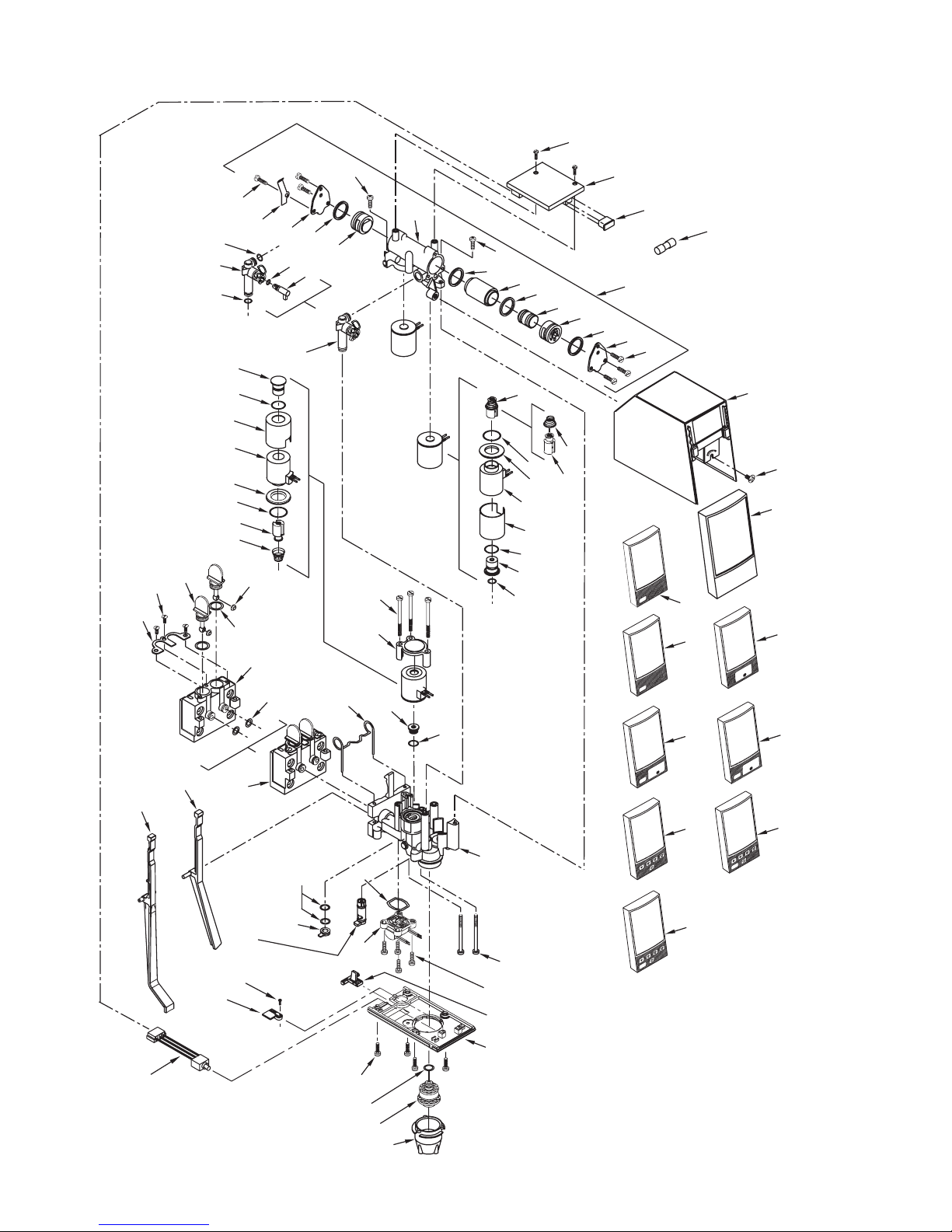
23. VOLUMETRIC VALVE ASSEMBLY
2
48
47
44
13
16
16
21
22
23
19
20
24
25
26
3
46
45
4
49
50
37
7
5
6
15
11
14
37
8
9
8
10
42
62
11
1
63
66
61
6
5
3
51
26
22
24
23
25
12
52
21
20
27
28
17
18
16
30
ER
WAT
53
54
SODA
55
PUSH
31b
64
31a
65
43
34a
34b
34c
3
32
33
36
35
3
16
40
41
16
29
37
38
39
17
56
PUSH
WATER
58
WATER
57
PUSH
SODA
59
60
SODA
26
Page 27

23. VOLUMETRIC VALVE PARTS LIST
Item Part No. Description CCUSA
R 1 52-2345/05 PCB Assy 24155
2 04-0640 Screw, 4 - 20 24208
R 3 04-0633/01 Screw, 6 - 19 x 0.437 24209
4 03-0188 Spring, Lever 24210
R 5 03-0187 Retainer, Syrup 24211
6 02-0221 O-Ring 22363
R 7 54-0115/01 Body Assy, Meter 24212
Assy, Syrup
8 02-0264 O-Ring 24213
R 9 81-0298 Sleeve, Syrup 1070147
10 81-0347 Piston 24215
R 11 05-0940/02 Retainer, Piston 24216
R 12 04-0302 Screw 21691
R 13 54-0175 Tube, Down, Syrup,
Restrictor
R 14 05-1094 Restrictor, Syrup 24219
15 02-0085 O-Ring 10060
16 02-0005 O-Ring 10050
17 04-0637 Screw 24221
18 05-0707 Retainer, Soda, 24222
Solenoid
R 19 10-0877/03 Plug Nut, Soda, 1071045
Solenoid
R 20 02-0538 O-Ring 10061
R 21 81-0289 Bonnet, Sub-assy, 24214
Solenoid
R 22 12-0132/01-01 Coil 24225
R 23 04-0600 Washer, Solenoid 24226
24 02-0109 O-Ring 17428
R 25 23-1071 Core Assy 1071046
R 26 03-0180 Spring, Core 24228
R 27 10-0280/02 Plug Nut, Syrup 24230
28 03-0233 Retainer, Valve 24231
R 29 54-0178 Main Body Assy 24232
30 05-0706 Seat, Soda 24233
R 31a 54-0125/01 Lever Arm 24234
R 31b 54-0195 Self-Serve Lever 24235
32 05-0779/01 Plug, Regulator 24236
33 02-0003 O-Ring 10049
34a 54-0192 Flow Washer Assy, 24237
Red, 1.50 Ounces
34b 54-0193 Flow Washer Assy, 24238
White, 2.25 Ounces
34c 54-0194 Flow Washer Assy, 24239
Gray, 3.00 Ounces
R 35 54-0126 Meter Assy(Includes #36)
R 36 02-0354 O-Ring
37 04-0549 Screw, 6 - 19 X 0.625 24242
R 38* 05-1102 Filler, Plate, Bottom 24243
R 39 05-0960/01 Plate, Bottom 24244
R 40 54-0176/01 Diffuser, Body Assy 24245
R 41 05-2053 Nozzle 24246
R 42 54-0190 Down Tube, 24220
Restrictor Assy
R 43 82-0274 Mounting Block 19810
Item Part No. Description CCUSA
R 43 82-0274 Mounting Block 19810
R 44 05-0266/01 Valve Stem, 12270
Mounting Block
R 45 05-0267 Washer 12286
R 46 02-0047 O-Ring 15175
R 47 04-0269 Screw 19894
R 48 03-0087 Retainer, Valve, 12263
R 48 03-0087 Retainer, Valve, 12263
Mounting Block
R 49 05-0265/01 Mounting Block 12189
R 50 02-0126 O-Ring 10706
R 51 54-0029/02 Cover Sub-assy 23984
R 52 05-0287/02 ID Panel 21432
R 53 52-1571 ID Panel, 24251
Water Button
R 54 52-1572 ID Panel, 24252
Soda Button
R 55 52-1399 ID Panel, 24253
Push Button
R 56 52-1573 ID Panel, 24254
Push Button, Water
R 57 52-1574 ID Panel, 24255
Push Button, Soda
R 58 52-1575/02 ID Panel, 24256
Portion Control,
R 59 52-1576/02 ID Panel, 24257
Portion Control,Water
R 60 52-1577/02 ID Panel, 24258
Portion Control,Soda
R 61 82-1117/02 Meter Assy, Syrup 24217
R 62 82-1624 Core/Spring Assy 24229
(Includes Items 25 & 26)
R 63 05-1187 Cover, Programmer 1071044
Plug
R 64 52-2491 Harness Assy,Syrup Purge
R 65 05-1958 Holder. Purge Switch,
Volumetric Valve
R 66 12-0348 Fuse, 5 Amp, 5X15, 1070729
Fast Acting
R -- 52-1420/02 Hand Held 532179
Programmer Assy
*Model 150P - Pushbutton only
R in margin indicates change or revision
27
Page 28

Lancer Corp.
800-729-1500
Technical Support/Warranty: 800-729-1550
custserv@lancercorp.com
lancercorp.com
 Loading...