

Page 1
INSTALLATION AND SERVICE MANUAL
FOR
PURE LINK WATER SYSTEMS
Pure Link Storage System
LANCER SERIES 1300
DATE: 10/29/03
P.N. 28–0530/03
This Manual supersedes the Installation and Service Manual, 28-0530/02, dated 06/20/03.
6655 LANCER BLVD. • SAN ANTONIO, TEXAS 78219 USA • (210) 310-7000
"Lancer" is the registered trademark of Lancer • Copyright — 2003 by Lancer, all rights reserved.
FAX SALES • USA-CANADA – 210-310-7250
Warranty / Technical Support - Field • 800-729-1500
Customer Service • Domestic / International – 800-729-1500
SPECIFICA
TIONS
TANK DIMENSIONS
WIDTH 18.5 inches (47.0 cm)
HEIGHT 41.5 inches (105.4 cm)
HEIGHT WITH STAND 50.0 inches (127.0 cm)
WEIGHT
Shipping Weight - Complete 26.0 pounds (11.8 kg)
Gross Operating - Full of water 337.3 pounds (153.0 kg)
STORAGE CAPACITY
Storage Unit 38.5 Gallons (146 Liters)
LANCER PURE LINK WATER UNITS
Part Number
Description
85-1330-40 38.5 gallon storage tank
with shut off system
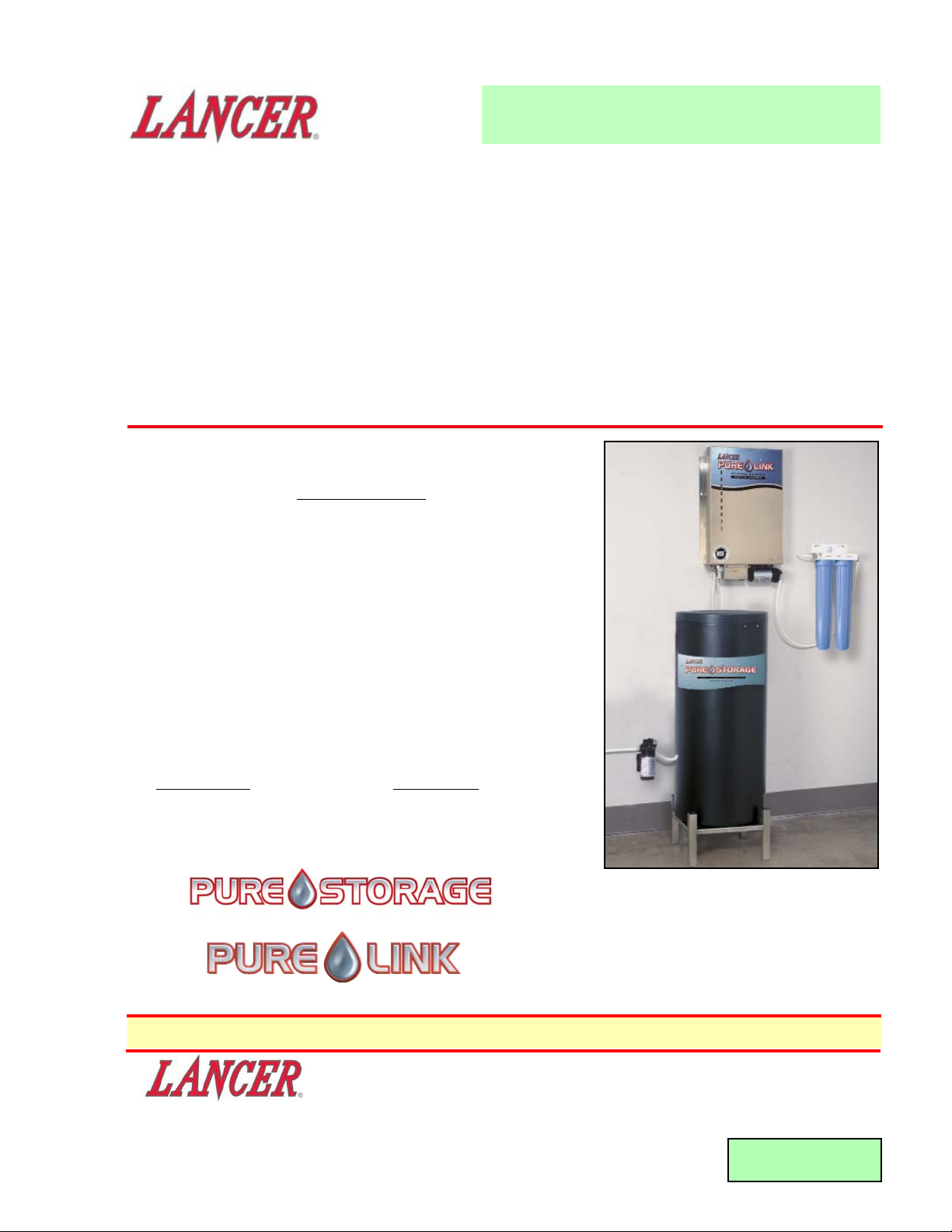
Installation showing black 38.5 Pure Storage
System as a complete water treatment system
(shown with optional stand with legs).
Please refer to the Lancer web site (www.lancercorp.com) for
information relating to Lancer Installation and Service Manuals,
Instruction Sheets, Technical Bulletins, Service Bulletins, etc.
• The Pure Storage Unit is an NSF certified
component.
• Prefilters and Delivery Pump shown above are
not performance tested or certified by NSF.
Page 2

TABLE OF CONTENTS
SPECIFICATIONS ...................................................................................................................................COVER
TABLE OF CONTENTS .....................................................................................................................................1
1. INSTALLATION ...........................................................................................................................................1
1.1 RECEIVING........................................................................................................................................1
1.2 UNPACKING ......................................................................................................................................1
1.3 SELECTING INSTALLATION LOCATION..........................................................................................1
1.4 INSTALLING OVERFLOW AND BAG CONNECTION TO DRAIN ....................................................2
1.5 CONNECTING THE STORAGE TANK TO PURE LINK REVERSE OSMOSIS SYSTEM................2
1.6 DELIVERY PUMP ..............................................................................................................................3
1.7 STARTING UNIT ................................................................................................................................3
1.8 SANITIZING AND PURGING SYSTEM UPON INSTALLATION .......................................................3
2. TYPES OF EQUIPMENT TO BE CONNECTED.........................................................................................4
2.1 FBD AND CARBONATOR METHOD .................................................................................................4
2.2 COFFEE, EXPRESSO AND ICE TEA METHOD...............................................................................4
3. CLEANING AND MAINTENANCE ..............................................................................................................4
3.1 FILTER REPLACEMENT ..................................................................................................................4
3.2 WATER QUALITY ..............................................................................................................................4
4. MEMBRANE REPLACEMENT INSTRUCTIONS .......................................................................................4
5. REPLACING THE STORAGE BAG............................................................................................................5
5.1 PURE LINK SYSTEM WITH 4 GALLON STORAGE BAG ................................................................5
5.2 PURE LINK STORAGE SYSTEM WITH 38.5 GALLON STORAGE BAG (PN 82-3234)..................5
6. TROUBLESHOOTING.................................................................................................................................6
6.1 UNIT NOT ACCEPTING WATER .......................................................................................................6
6.2 TANK WILL NOT SHUT OFF .............................................................................................................6
6.3 DELIVERY PUMP CANNOT DRAW WATER FROM TANK ..............................................................6
6.4 WATER IS INSIDE TANK...................................................................................................................6
6.5 BAG EMPTIES AND SYSTEM CANNOT KEEP UP WITH HOST UNIT...........................................6
7. ILLUSTRATIONS, PARTS LISTINGS, AND WIRING DIAGRAMS............................................................6
7.1 STAND (OPTIONAL EQUIPMENT)....................................................................................................6
7.2 LANCER PURE LINK STORAGE SYSTEM...................................................................................7-8
7.3 LANCER PRE-FILTER KIT, TWIN-PAC 5 MICRON (10” AND 20”)
(OPTIONAL EQUIPMENT).................................................................................................................8
7.4 LANCER PURE LINK DELIVERY PUMP, PN 86-0139 (OPTIONAL EQUIPMENT) .........................9
7.5 LANCER PURE LINK DELIVERY PUMP, PN 86-0132 (OPTIONAL EQUIPMENT) .........................9
TUBE CONNECTIONS ....................................................................................................................................10
CERTIFICATE OF WARRANTY ......................................................................................................................11
1
1. INSTALLATION
1.1 RECEIVING
Each unit is completely tested and thoroughly inspected before shipment. At the time of shipment,
the carrier accepts the unit and any claim for damage(s) must be made with the carrier. Upon
receiving units from the delivering carrier, carefully inspect carton for visible indication(s) of
damage. If damage exists, have carrier note same on bill of lading and file a claim with the carrier.
1.2 UNPACKING
A. Remove the unit from carton.
B. Remove inner carton pads and inserts.
C. Remove Installation Kit of loose parts.
D. Inspect for concealed damage(s) and if evident, notify delivering carrier and file claim against
same.
1.3 SELECTING INSTALLATION LOCATION
A. Insure that the Pure Link reverse osmosis (RO) system has been installed prior to installing the
Pure Link Storage System. Refer to the Pure Link manual (Lancer PN 28-0461/XX) for proper
installation instructions. In order to provide sufficient gravity feed pressure from the Pure Link
RO system to the storage tank, ensure a minimum vertical clearance of ten inches (10”) is
provided between the top of the storage tank and the bottom of the Pure Link wall unit (see
Figure 1).
Page 3
B. The Pure LInk Storage System is designed for placement directly on the floor or for use with the
optional floor stand (Lancer PN 82-3251 or 82-3275). The floor space selected must be
capable of holding 337.3 pounds (153 kg), an optional stand (16.25” x 16.25”), and the tank
(18.5” in diameter). Select a location that is close to a drain and close enough to the Pure Link
RO system so the system can gravity feed to the storage unit.
C. Locate the storage system in the desired location. Ensure that unit is properly secured if the
floor is not level (Optional Floor Stand, Lancer PN 82-3275, includes adjustable levelers).
1.4 INSTALLING OVERFLOW AND BAG CONNECTION TO DRAIN
NOTE:
Review Sanitizing Instructions (see Section 1.8) before proceeding with the actual installation.
A. There are two drain connections located on the side of the tank, marked "DRAIN". One 1/4”
drain connector is provided for the bag vent overflow and a 1/2" drain connector is provided as
an emergency overflow in the event the bag should become damaged. Using 1/4" OD tubing,
connect to the proper fitting on the side of the tank and to the nearest drain location. Using 1/2"
OD tubing, connect to the proper connector on the side of the tank and to the nearest drain (see
Figure 1). Follow local plumbing codes for air gap requirements.
B. The only time any water will flow from the 1/4" OD drain connector is if there is a failure of the
shut off valve to operate correctly and the unit continues to produce water, overfilling the
storage bag . The only time water will flow from the 1/2" OD fitting is if the bag becomes
damaged and leaks into the tank internally.
CAUTION
FAILURE TO PROPERLY INSTALL THE OVERFLOW ASSEMBLY OR PLUMB IT TO THE DRAIN
COULD RESULT IN WATER DAMAGE.
2
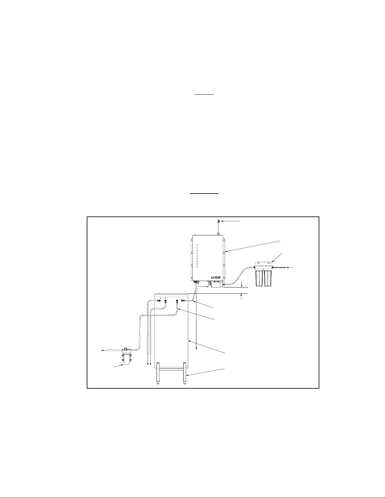
EMERGENCY
OVERFLOW
TO DRAIN
(VENT OVERFLOW)
TO DRAIN
BRINE WATER
TO DRAIN
STORAGE TANK,
PURE WATER
FLOOR STAND,
OPTIONAL
PURE LINK UNIT
PRE-FILTER KIT
WATER INLET
TO POINT
OF USE
(POU)
DELIVERY
PUMP
PRODUCT WATER IN
PRODUCT WATER OUT TO PUMP
MINIMUM CLEARANCE - 10 INCHES
Pure Link Plumbing Diagram
Figure 1
1.5 CONNECTING THE STORAGE TANK TO PURE LINK REVERSE OSMOSIS SYSTEM
The Pure Link Storage unit is designed to be used with the Lancer Pure Link reverse osmosis system only.
(Use with other types of reverse osmosis systems or filtration systems could cause failure
of the unit.) The tank has a connection on the side of the unit (marked "Water In") which is the
gravity feed port to accept water from the Pure Link unit. On the bottom of the Pure Link unit, there
is a 3/8" OD connector (marked "Product Water"). This location will allow water to gravity feed to
Page 4

3
the tank. Connect 3/8" OD tubing from the Pure Link system(s) to the tank at the designated ports
(see Figure 1).
NOTE:
The tubing should be routed directly from the Pure Link Unit to provide gravity flow to the Storage
Tank. Avoid low sections of tubing which could accumulate water or impede flow.
1.6 DELIVERY PUMP
A. Locate the "Product Water" connector on the side of the tank. Using 1/2" ID tubing, connect to
the inlet side of the pump using the proper fittings enclosed. (Refer to delivery pump
installation instructions for proper installation.)
B. Ensure that delivery pump is properly sized to meet the demand of the point(s) of use(s) (POU).
C. To ensure proper operation, the delivery pump must be installed below the tank level (see
Figure 1).
1.7 STARTING UNIT
A. Refer to the Pure Link Installation and Service Manual (28-0461/02) for system start up.
B. Flush and fill Pure Link unit per start-up instructions provided in the Pure Link Manual prior to
connecting to Storage Tank.
C. Once the Pure Link system is operational and the tank has been plumbed properly, the tank
function is fully automatic.
D. When unit is operating, check for leaks. The Pure Link System will begin to produce water to
fill the storage system. The time required to fill the storage tank is dependent upon the Pure
Link Unit selected for the application and the related water production rate.
1.8 SANITIZING AND PURGING SYSTEM UPON INSTALLATION
NOTE:
When connecting to steamers, dough proofers, and ice makers, the equipment must be cleaned,
descaled, and sanitized in accordance with the manufacturer's instructions - prior to the operation
of Pure Link unit(s)
.
A. This equipment must be sanitized according to manufacturer's instructions at the time of
installation to ensure the level of purity in the product water expected of a Reverse Osmosis
system. The operator of this equipment must provide continuous maintenance as required by
this manual and/or state and local health department guidelines to ensure proper operation and
sanitation requirements are maintained.
NOTE:
The cleaning and sanitizing procedures provided
herein pertain to the Lancer equipment
identified by this manual. If other equipment is being
cleaned, follow the guidelines established by the
manufacturer for that equipment.
1. Cleaning and sanitizing should be accomplished
only by trained personnel. Sanitary gloves are to
be used during cleaning and sanitizing
operations. Applicable safety precautions must
be observed. Instruction warnings on the
product being used must be followed.
View Looking down at top of Tank,
Lid removed
Figure 2
the manufacturer's written recommendations and safety guidelines. Adding one (1 oz.)
packet will provide 6.5 parts per million (ppm) available chlorine with the 38.5 gallon
storage capacity of the Pure Link Storage System.
2. An equivalent sanitizer may be substituted as long as it is prepared in accordance with the
manufacturer's written recommendations and safety guidelines, and provides 6.5 ppm
available chlorine when diluted with the 38.5 gallon storage capacity.
B. Recommended Preparation of Sanitizing Solution
1. The Installation Kit includes one (1 oz.) packet of
Kay-5
® Sanitizer for sanitizing at start-up. This
solution should be prepared in accordance with
Remove Cap here to add Sanitizer
Page 5

4
C. Sanitizing and Initial Bag Filling
1. Remove four (4) screws holding tank lid in place, remove lid, set aside for reinstallation.
2. Locate bag cap (flat translucent cap) and remove (see Figure 2).
3. Empty contents of one (1 oz.) packet Kay-5
® Sanitizer into storage bag through bag fitting.
4. Reinstall bag cap to bag connector, ensuring cap is fully engaged with connector.
5. Connect water source to "Product Water In" fitting and fill tank to shut off.
NOTE:
Storage bag is inflated with Nitrogen to prevent shifting during shipment, this will vent off as
the bag fills with water. During initial bag fill some adjustment of the bag may be required.
Ensure that bag is centered in tank and fills evenly providing proper shut off without
"stretching" on one side.
6. Connect applicable delivery pump to "Product Water Out" fitting of tank (see Section 1.6).
7. Pump entire water contents from bag to drain.
8. Readjust bag if necessary.
9. Follow Installation instructions to connect Pure Link, Delivery Pump and Point of Use.
10. Replace tank lid and secure with 4 screws removed in step A.1 above.
2. TYPES OF EQUIPMENT TO BE CONNECTED
• FBD • Coffee Machine • Ice Tea (if installed) • Steamer
• Espresso Machine • Carbonator • Proofer • Ice Machine
2.1. FBD and Carbonator Method
Gravity feed or remote pump system from "Product Water" port of Storage Tank.
2.2. Coffee, Espresso, and Ice Tea Method
Use remote delivery pump kit (Lancer Kit PN: 82-3202, 86-0139, or 86-0132, 115 VAC). See
Lancer Catalog or call Lancer Customer Service for other Delivery Applications.
3. CLEANING AND MAINTENANCE
NOTE:
The Reverse Osmosis System contains a replaceable treatment component critical for effective reduction of
dissolved solids. The product water shall be tested periodically to verify that the system is performing properly.
TDS Sampling Kits and/or meters are available through Lancer Customer Service.
3.1 FILTER REPLACEMENT
Periodic replacement of the sediment pre-filter and carbon block filter should be accomplished in
accordance with the manufacturer's instructions. Replacement of pre-filter and carbon block
cartridges should be scheduled as necessary with regard to filter size, feed water quality, and water
volume usage. Regular scheduled maintenance of the pre-filter is required to prevent premature
failure of Pure Link system components.
3.2 WATER QUALITY
Periodic water quality testing of the Product Water is recommended every six (6) months at a
minimum. When TDS reduction of system is less than 80% compared to untreated feed water,
Lancer recommends replacement of the Membrane Module(s). Sanitizing procedures should be
followed when necessary to reduce bacteria growth. See Section 1.8 of this Manual.
4. MEMBRANE REPLACEMENT INSTRUCTIONS
4.1 Disconnect electrical supply to Pure Link unit, if applicable.
4.2 Turn off water supply.
4.3 Drain water from storage bag.
4.4 Remove the five screws that secure the enclosure cover and remove cover (save screws for
reinstallation).
4.5 Remove 1/4" tubing from membrane module(s) by holding down color coded collet on membrane
Page 6

port while pulling on tubing. Take care to note tube placement for reinstallation of replacement
membrane module(s).
NOTE:
Blue collet is feed water inlet, White collet is product water out, Red collet is brine water to drain.
Ensure that Flow Restrictor is properly seated in brine tube before insertion into red collet of
replacement membrane module. Flow Restrictor for single membrane unit is white, double
membrane unit is gray.
4.6 Remove membrane module(s) from mounting clips by firmly pulling out one end and then the other.
4.7 Install replacement membrane modules by firmly pressing into one mounting clip and then the other.
4.8 Reinstall 1/4" tubing to appropriate membrane ports. See Figures 3 and 4 for plumbing diagrams.
Ensure tubing is fully seated into fittings.
4.9 Turn on water supply and connect electrical supply, if applicable.
4.10 Check for leaks, and tighten connections if necessary.
4.11 Replace cover and secure with screws retained from Step 4.4 above. Do not allow bag to fill above
top of bag shelf before cover is in place.
4.12 Follow Membrane Flushing procedures as outlined in Section 1.8, this manual.
4.13 Lancer recommends replacing the storage bag when membrane module(s) are replaced.
Single Membrane - Plumbing Diagram
Figure 3
Double Membrane - Plumbing Diagram
Figure 4
5. REPLACING THE STORAGE BAG
5.1 PURE LINK SYSTEM WITH 4 GALLON STORAGE BAG
Refer to Lancer Installation and Service manual 28-0461/02, Pure Link Water Systems, Lancer
Series 1300, for information replacing the storage bag in the Pure Link unit.
5.2 PURE LINK STORAGE SYSTEM WITH 38.5 GALLON STORAGE BAG (LANCER PN 82-3234)
A. Empty contents of storage bag to drain, using applicable delivery pump.
B. Disconnect delivery pump from electrical supply.
C. Disconnect product water feed supply to storage tank.
D. With tank cover off of unit, locate bag connectors mounted to center bracket.
E. Remove the 4 fittings from the bag connectors:
1. Water feed supply from shut off valve
2. Vent fitting assembly
3. Dip Tube assembly
4. Translucent bag cap
F. Remove 4 screws holding bag mounting bracket to tank; set screws aside for reinstallation.
G. Raise bracket outside of tank far enough to access the bag fittings.
H. Slide fittings one at a time along the notch in the bracket toward the large clearance opening,
5
TO STORAGE BAG
WATER OUT
INLET WATER
TO DRAIN
TO STORAGE BAG
WATER OUT
TO DRAIN
WATER IN
Page 7

and pull away from bracket.
I. Install new bag in reverse manner, ensure bag is not twisted in tank.
J. Reinstall bag mounting bracket with 4 screws retained from Step F above.
K. Reinstall fittings and cap removed in Step 5 to bag connectors.
L. Proceed to Sanitizing and Start Up Instructions, Section 1.8.
6. TROUBLE SHOOTING
TROUBLE
CAUSE REMEDY
6.1 Tank not accepting A. Pure Link unit not operating. A. Refer to Pure Link manual,
water. 28-0461.
B. Restriction in line between B. Check line for bend.
tank and Pure Link unit.
C. Shut off on top of tank may C. Ensure shut off plate has free
be stuck. movement.
6.2 Tank will not shut off. A. Shut off on top of tank may A. Ensure shut off plate has free
be stuck. movement.
6.3 Delivery pump cannot A. Connector inside tank A. Check all tubing connectors to
draw water from tank. came off. ensure they are properly in
place.
B. Bag has obstructed dip tube. B. Remove obstruction.
C. Delivery pump is not C. Check pump manual.
functioning properly.
6.4 Water is inside of tank. A. Inlet or bag connector has A. Insure all connectors are tight.
come off.
B. Bag is damaged. B. Inspect bag for leaks. Replace
if necessary.
6.5 Bag empties and system A. Host machine has A. Contact your local service agent.
cannot keep up with host malfunction.
unit. B. Pure Link production rate is B. Refer to Pure Link Manual,
inadequate for application. 28-0461.
6
ITEM PART NO. DESCRIPTION
-- 82-3275 Stand Assy, Support, with Adjustable
Legs
-- 82-3251 Stand Assy, Support
1 51-5950 Support, Stand, 38.5 Gallon
2 05-1995 Plug, 1.5 x 1.5
3 81-0030 Leg/Foot, Adjustable, 1.5 Square
Tube
7. ILLUSTRATIONS AND PARTS LISTINGS
7.1 STAND (OPTIONAL EQUIPMENT)
1
2
3
Page 8

7
1
13
2
3
4
5
7
8
9
4
10
11
12
14
15
20
17
18
16
17
21
22
23
24
25
PRODUCT
WATER
OUT
PRODUCT
WATER
IN
PLUMBING DIAGRAM
VENT TO
DRAIN
OVERFLOW
TO DRAIN
29
30
28
27
26
29
6
19
7.2 LANCER PURE LINK STORAGE SYSTEM
NOTE:
Lancer uses only genuine John
Guest fittings in manufacturing
the Pure Link system and
associated components.
Page 9

8
ITEM
PART NO. DESCRIPTION
1 82-3234 Bag Assy, 38.5 Gallon, RO
2 66-1032 Cap, Dust, Bag, RO
3 82-3241 Tube Assy, DIP, 38.5 Gallon
Storage
4 07-0452 Clamp, STPLS, Oetiker
5 04-0510 Screw, 8 - 18 X 0.500, PH
6 01-2100 Fitting, Tee, 1/4”, JG
7 08-0298 Tubing, Braided, 1/2 x 3/4
8 01-2072 Elbow, Union, 3/8
9 82-3010 Spout, Sub-Assy, Pure LInk
10 01-2406 Fitting, 1/2 Tube x 1/2 Barb
11 82-3402 Vent, Sub-Assy, Pure Link
12 08-0414 Tubing, LLDPE, JG, 1/4” OD
13 01-2084 Elbow, Plug In, 3/8 x 3/8
14 06-2684 Decal, Pure Link Storage System
15 04-0397 Screw, 8 - 16 X 0.500, PH, SS
ITEM PART NO. DESCRIPTION
16 06-2720 Tag, Product Water OUT
17 01-2083 Fitting, Bulkhead, 1/2
18 01-2087 Fitting, Bulkhead, 1/4”, JG
19 06-2571 Tag, Drain, RO
20 06-2719 Tag, Drain, RO
21 66-1039 Plug, Cap, 1.5”, Black
22 06-2721 Tag, Product Water, IN
23 01-2075 Fitting, Bulkhead, 3/8
24 66-1027 Plug, 1.5”, 3/8”, Yellow
25 05-2051 Tank, Storage, 38.5 Gallon
26 27-0080 Lever, Shutoff, Storage Unit
27 04-1241 Nut, Jam, Nylon, 5/8 - 20
28 27-0078 Bracket, Bag, Shutoff, Storage
29 08-0415 Tubing, LLDPE, JG, 3/8”, OD
30 17-0579 Valve, Shutoff, LPL, 3/8
7.3 LANCER PRE-FILTER KIT, TWIN-PAC 5 MICRON (10” AND 20”) (OPTIONAL EQUIPMENT)
ITEM
PART NO. DESCRIPTION
-- 82-3021 10” Sump Kit, Twin-Pac, 5 Micron
-- 82-3078 20” Sump Kit, Twin-Pac, 5 Micron
1 82-3074 10” Pre-filter Cartridge, 5 Micron
-- 82-3081 20” Pre-filter Cartridge, 5 Micron
2 82-3075 10” Carbon Block Cartridge, 5 Micron
-- 82-3082 20” Carbon Block Cartridge, 5 Micron
7.2 LANCER PURE LINK STORAGE SYSTEM (CONTINUED)
1
2
Page 10

9
7.5 LANCER PURE LINK DELIVERY PUMP, PN 86-0132 (OPTIONAL EQUIPMENT)
ITEM PART NO. DESCRIPTION
1 86-0132 Pump, Delivery, 115V, Variable
Speed, 4.5 GPM (open Flow)
2 01-2392 Fitting, Quick Connect x1/2 Barb,
Straight (Standard Fitting)
3 01-2393 Fitting, Quick Connect x1/2 Barb,
90 Degree Elbow (Optional
Fitting)
7.4 LANCER PURE LINK DELIVERY PUMP, PN 86-0139 (OPTIONAL EQUIPMENT)
ITEM PART NO. DESCRIPTION
1 86-0139 Pump, Delivery, 115V, Variable Speed,
1.2 GPM (Open Flow)
2 01-2392 Fitting, Quick Connect x1/2 Barb,
Straight (Standard Fitting)
3 01-2393 Fitting, Quick Connect x1/2 Barb, 90
Degree Elbow (Optional Fitting)
1
3
2
1
3
2
Page 11

10
TUBE CONNECTIONS
NOTE: Lancer uses only genuine John Guest fittings in manufacturing the Pure Link system and associated components.
How to make a connection
To make a connection, the tube is simply pushed in by hand. The uniquely patented John Guest collet
locking system then holds the tube firmly in place without deforming it or restricting flow.
1. Cut Tube Square
Cut the tube square. It is essential that the outside diameter be free of score
marks and that burrs and sharp edges be removed before inserting into
fitting. For soft thin walled plastic tubing, we recommend the use of a tube insert.
Fitting grips before it seals. Ensure tube is pushed into the tube stop.
2. Insert Tube
4. Pull to check secure
3. Push up to Tube stop
Disconnecting
Push in collet and remove tube
Push the tube into the fitting, to the tube stop. The collet (gripper) has
stainless steel teeth which hold the tube firmly in position while the O-Ring provides
a permanent leak proof seal.
To disconnect, ensure the system is depressurized before removing the tube. Push in
collet squarely against face of fitting. With the collet held in this position, the tube can
be removed. The fitting can then be re-used.
Pull on the tube to check that it is secure. It is a good practice to test the system
prior to leaving site and/or before use.
Page 12

11
PARTS AND EQUIPMENT LIMITED WARRANTY
LANCER® warrants new replacement parts, equipment, and hermetically sealed refrigeration
systems (HSRS) to be free from defects in material and workmanship under normal use and
service. The duration of the warranty for these different items is shown below.
LANCER®‘s
obligation, hereunder, shall be limited to repairing or replacing any part, or part of said
equipment or system which our examination discloses to be defective and which has not been
subjected to any accident, negligence, alteration, abuse or misuse, and additionally in the case
of refrigeration and/or electrical systems, not subjected to high, low or fluctuating electrical
voltage.
LANCER®‘s obligation does not provide for service calls from factory representatives
or from any other agency and shall not include reimbursement for labor charges incident to
removal of any parts or the reinstallation of the same.
LANCER® will accept parts, equipment,
and refrigeration systems freight prepaid by sender. LANCER® will assume freight charges
within the continental United States, or to a port of export within the continental United States
for international shipments.
LANCER
®
will not be responsible for international freight, customs
fees or duties at country of destination. In the event LANCER® establishes sales and service
organizations outside the continental limits of the United States, the point of shipment of
repaired or replaced parts or equipment may, at
LANCER® option, be made from that location,
with freight charges assumed to the point of export from the country in which a sales and
service organization is established.
Warranty Periods
Par
ts:
Ninety (90) days from date of original shipment from a LANCER®facility or from
an authorized Lancer Distributor.
Equipment:
One (1) year from date of original shipment from a LANCER®facility or from an
authorized Lancer Distributor.
Hermetically Sealed Refrigeration System:
For the following components of the HSRS, i.e., the compressor, condenser,
evaporator, coldpack, capillary tubes, and drier, five (5) years from date of original
shipment from a
LANCER® facility or from an authorized Lancer Distributor.
All other parts of the HSRS, one (1) year from date of original shipment from a
LANCER
®
facility or from an authorized Lancer Distributor.
EXCEPT AS SPECIFICALLY SET FORTH HEREIN,
LANCER® MAKES NO EXPRESS
WARRANTIES AS TO ANY MATTER WHATSOEVER AND HEREBY DISCLAIMS ALL
IMPLIED WARRANTIES INCLUDING, WITHOUT LIMITATION, THE IMPLIED WARRANTIES
OF MERCHANTABILITY AND FITNESS FOR ANY PARTICULAR PURPOSE. IN NO EVENT
SHALL
LANCER® BE LIABLE OR OBLIGATED TO CUSTOMER OR TO ANY THIRD PARTY
FOR INCIDENTAL, CONSEQUENTIAL, OR SPECIAL DAMAGES, REGARDLESS OF THE
THEORY OF LIABILITY, ARISING OUT OF, OR IN ANY MANNER RELATED TO LANCER
®
PARTS, EQUIPMENT, OR HSRS, OR ANY DELAY WITH RESPECT TO ITS DELIVERY.
REV: 01/16/01
P.N.: 38-0508/03
 Loading...