

Page 1
INSTALLATION AND SERVICE MANUAL
FOR THE
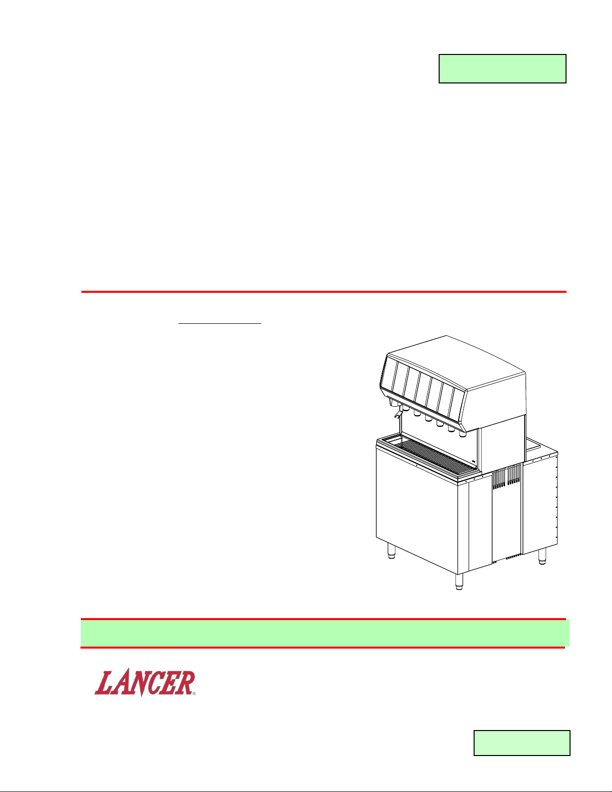
MB-18, HIGH VOLUME FREE STANDING
FOUNTAIN DRINK DISPENSER
Part Number 85-10018-126, 115 Volts, 60 Hz
SPECIFICATIONS
DIMENSIONS
Width 36 inches (91.4 cm)
Depth 36 inches (91.4 cm)
Height To Countertop 36 inches (91.4 cm)
To Top of Shroud 61 inches (154.9 cm)
WEIGHT
Shipping 600 pounds (272 kg)
Empty 530 pounds (240 kg)
Operating 800 pounds (363 kg)
ELECTRICAL
Operating Voltage 115
Hertz 60
Amps 20
This initial (draft) issue is released for field test purposes ONLY!!!
DATE: 06/18/01
P.N. 28–0466
6655 LANCER BLVD. • SAN ANTONIO, TEXAS 78219 USA • (210) 310-7000
FAX SALES
• USA -CANADA – 210-310-7250 • LATIN AMERICA – 210-310-7245 • ASIA – 210-310-7242
• EUROPE – 32-2-755-2399 • PACIFIC – 61-8-8268-1978
FAX ENGINEERING: • 210-310-7096
"Lancer" is the registered trademark of Lancer • Copyright — 2001 by Lancer, all rights reserved.
Check out the Lancer web site:
www.lancercorp.com
Page 2

T
ABLE OF CONTENTS
SPECIFICATIONS ...................................................................................................................................COVER
TABLE OF CONTENTS ......................................................................................................................................i
MANUFACTURER’S INTRODUCTION ..............................................................................................................i
1. INSTALLATION ...........................................................................................................................................1
1.1 RECEIVING........................................................................................................................................1
1.2 UNPACKING ......................................................................................................................................1
1.3 SELECTING LOCATION....................................................................................................................1
1.4 PLUMBING.........................................................................................................................................1
1.5 ELECTRIC POWER SUPPLY ............................................................................................................2
1.6 SYSTEM CHECK ...............................................................................................................................2
2. START UP, PERIODIC MAINTENANCE, CHECKLIST, AND CLEANING GUIDE ....................................2
2.1 CLEANING AND SANITIZING INSTRUCTIONS ...............................................................................2
2.2 PERIODIC MAINTENANCE, CHECKLIST, AND CLEANING GUIDE ...............................................3
2.3 CLEANING AND SANITIZING BEVERAGE COMPONENTS - FIGAL SYSTEMS............................4
2.4 CLEANING AND SANITIZING BEVERAGE COMPONENTS - BAG-IN-BOX SYSTEMS.................5
3. HOW TO OPERATE THE LANCER MB-18 ................................................................................................6
3.1 NORMAL OPERATION ......................................................................................................................6
3.2 PROGRAMMING AND SETUP SOFTWARE.....................................................................................6
4. MB-18 TROUBLESHOOTING GUIDE ........................................................................................................8
4.1 PUSH ICE LEVER/CHUTE/ICE BUTTON AND NOTHING HAPPENS.............................................8
4.2 PUSH CHUTE MOTOR RUNS BUT NO ICE DISPENSES...............................................................8
4.3 VALVES DO NOT OPERATE .............................................................................................................8
4.4 WATER IN ICE BIN ............................................................................................................................8
5. ILLUSTRATIONS, PARTS LISTINGS, AND WIRING DIAGRAMS............................................................8
MB18 SERVICE PARTS ..............................................................................................................................8
BIN ASSEMBLY .................................................................................................................................8
AGITATOR MOTOR ASSEMBLY .......................................................................................................8
AUGER ASSEMBLY...........................................................................................................................9
ICE CHUTE ASSEMBLY ....................................................................................................................9
TOWER ASSEMBLY ..........................................................................................................................9
SHROUD ASSEMBLY......................................................................................................................10
FINAL ASSEMBLY ...........................................................................................................................10
POWER SUPPLY ASSEMBLY.........................................................................................................10
i
MANUFACTURERS INTRODUCTION
High Volume Free Standing Fountain Drink Dispenser
The unit is designed with the highest quality components to be user and service friendly. Most set up
parameters are easily set via a serial interface and an infrared wireless data port. All control is handled by the
on board microprocessor controller. The MB-18 is designed to seamlessly interface with the Lancer IceLink
system to provide for a minimum of labor and maintenance by store personnel.
The MB-18 features multiple speed ice dispense from an under counter ice storage bin which is also used to
chill the product utilizing a flexible, high performance cold plate system. Up to 18 independent brands may be
dispensed through six (6) Lancer Multi-Flavor dispense nozzles. In addition, 12 ambient (non-chilled) "bonus"
flavors may be added to the drink via the flavor injection system on four (4) nozzles. Up to three (3) flavors
may be added to each of four (4) nozzle positions. The bonus flavors are plumbed independently to each of the
nozzles allowing for a multitude of customer pleasing drink combinations.
Supplier Name: Lancer
Address: 6655 Lancer Blvd
San Antonio, TX 78219
Phone: (800) 729-1500
Local Service Name:
Local Service Phone #:
Page 3
1. INSTALLATION
1.1 RECEIVING
Each unit is completely tested under operating conditions and thoroughly inspected before shipment.
At time of shipment the carrier accepts the unit, and any claim for damage must be made with the
carrier. Upon receiving units from the delivering carrier, carefully inspect carton for visible indication
of damage. If damage exists, have carrier note same on bill of lading and file claim with carrier.
1.2 UNPACKING
A. Set shipping carton upright on the floor.
B. Cut band and remove.
C. Open top of carton and remove interior packing.
D. Lift carton up and off of the dispenser.
E. Remove wood shipping base from the bottom of the dispenser. (Support dispenser while
removing shipping base to prevent damage to the dispenser.)
1.3 SELECTING LOCATION
A. Select a location close to a properly grounded 20 Amp electrical outlet, convenient to an open
type drain, and access for soda, water, and syrup lines. If at all possible, location should be
away from direct sunlight or other heat sources.
B. Location must insure sufficient clearance above unit to provide for servicing.
1.4 PLUMBING
NOTE
Water pipe connections and fixtures directly connected to a potable water supply and drain
plumbing connections must all be sized, installed, and maintained according to Federal, State,
and Local laws.
The water supply must be protected by means of an air gap, a backflow prevention device
(located upstream of the CO
2 injection system) or another approved method to comply with
NSF standards. A backflow prevention device must comply with ASSE and local standards.
It is the responsibility of the installer to ensure compliance.
1
A. General Product Configuration
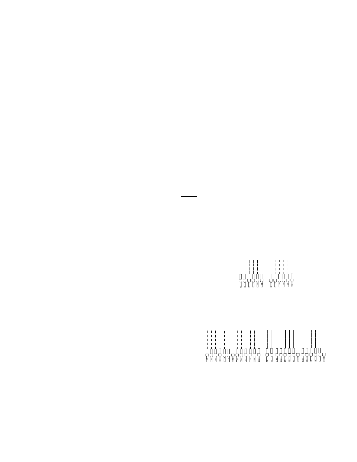
1. The MB-18 is equipped with nine (9)
independent soda/water inlets (see
Figure 1 for detail). An individual
module that can be plumbed for either
soda or still water supports each nozzle
location. In addition, nozzles 3, 4 and 5
are provided with a second module that
will also support soda or still water. This
is to provide for maximum flexibility and
performance from all circuits and
products.
2. Depending on the specific use volume
at the installation, the use of either one
or two Lancer Turbo Carbonators is
recommended. Locations serving
larger drink sizes and/or higher drink
volume will require a second Turbo
Carbonator. In addition, the use of a
high capacity plain water boost system
is recommended if incoming water
pressure is below 50 psi under demand
conditions.
Nozzle Inlets
Figure 1
IS4-3
IS4-2
IS4-1
IS3-3
IS3-2
IS3-1
IS2-3
IS2-2
IS2-1
IS1-3
IS1-2
IS1-1
INJECTION FLAVORS
RIGHT SIDE OF UNIT
S1-1
S1-2
S1-3
S2-1
S2-2
S3-1
S3-2
S3-3
S4-1
S4-2
S5-1
S5-2
S5-3
S6-1
S2-3
S4-3
S6-2
S6-3
SODA-1
SODA-2
SODA-3
SODA-4
SODA-5
SODA-6
WATER-3
WATER-4
WATER-5
COLD PLATE INLETS
LEGEND:
S1 - 1 = SYRUP, NOZZLE 1, PLACE 1
IS1 - 1 = INJECTION SYRUP, NOZZLE 1, PLACE 1
Page 4

2
B. Drain Connections
The MB-18 Features two (2) 3/4" MPT connections on the left side (from the front) of the
machine for the cold plate drain system and a third (3rd) 3/4" FPT fitting for the drip tray drain
located on the right hand side of the machine. The cold plate drains should be plumbed
independent from the drip tray drain and adequate slope and air gap should be provided to
prevent back up and potential contamination. Drain lines should be insulated with a closed cell
insulation to prevent condensation. Use caution to prevent gaps in insulation that can cause
condensation traps.
C. Water/Soda and Syrup Connections
Connect plain and carbonated water lines as desired. Refer to Figure 1 for details. All water
and chilled syrup (brands) are 3/8" barb. All ambient syrups (flavors) are 1/4" barb. Pressurize
and test the system for leaks.
1.5 ELECTRIC POWER SUPPLY
W
ARNING:
THIS APPLIANCE MUST BE EARTHED. THIS DISPENSER MUST BE ELECTRICALLY
GROUNDED TO AVOID DANGER TO THE OPERATOR. THE POWER CORD PROVIDED HAS
A THREE PRONG GROUNDED PLUG. IF A THREE HOLED GROUNDED ELECTRICAL
OUTLET IS NOT AVAILABLE, USE AN APPROVED METHOD OF INSURING A PROPER
GROUND TO THE DISPENSER.
NOTE
Electrical connections must be installed and maintained in accordance with Federal, State, and
Local requirements.
A. The electric power supply must be a 20 amp three prong, ground convenience outlet having the
same configuration as the power cord.
B. Outlet must have proper voltage, cycles and ampere ratings. See Dispenser Name Plate for
ratings.
NOTE
Do not plug into electrical outlet unless ratings on name plate agree with local current available.
1.6 SYSTEM CHECK
W
ARNING:
ICE AUGER AND BIN AGITATION SYSTEM WILL OPERATE AUTOMATICALLY. DO NOT
PLACE HANDS OR ANY BODY PARTS WITHIN THE BIN OR IN THE ICE CHUTE.
A. With power connected, remove drip tray assembly and sanitary cover from ice bin. Raise the
tower shroud by lifting at the front. Use the provided prop rod to secure the shroud in the raised
position.
B. Push on ice cup lever to activate ice auger and bin agitation system. Verify auger rotation by
viewing through the ice chute door. Verify bin agitator rotation inside ice bin.
2. START UP, PERIODIC MAINTENANCE, CHECKLIST, AND CLEANING GUIDE
2.1 CLEANING AND SANITIZING INSTRUCTIONS
A. GENERAL INFORMATION
1. Lancer equipment (new or reconditioned) is shipped from the factory cleaned and sanitized
in accordance with NSF guidelines. This equipment must be cleaned and sanitized after
installation is complete, and the operator of the equipment must provide continuous
maintenance as required by this manual and/or state and local health department
guidelines to ensure proper operation and sanitation requirements are maintained.
NOTE
The cleaning and sanitizing procedures provided herein pertain to the Lancer equipment
identified by this manual. If other equipment is being cleaned, follow the guidelines
Page 5

3
established for that equipment.
2. Cleaning and sanitizing should be accomplished only by trained personnel. Sanitary gloves
are to be used during cleaning and sanitizing operations. Applicable safety precautions
must be observed. Instruction warnings on the product being used must be followed.
3. Water lines are not to be disconnected during the cleaning and sanitizing of syrup lines to
avoid contamination.
4. Do NOT use strong bleaches or detergents. They tend to discolor and/or corrode various
materials.
5. Do NOT use metal scrapers, sharp objects, steel wool, scouring pads, abrasives, solvents,
etc., on the dispenser.
6. Do NOT use hot water above 140°F (60°C). This may damage certain materials.
B. REQUIRED CLEANING EQUIPMENT
1. Cleansers (for example, Ivory Liquid, Calgon, etc.) mixed with clean, potable water at a
temperature of 90 to 110 degrees Fahrenheit should be used to clean equipment. The
mixture ratio, using Ivory Liquid, is one (1) ounce of cleanser to two (2) gallons of water. A
minimum of five (5) gallons of cleaning mixture should be prepared. Any equivalent
cleanser may be used as long as it provides a caustic based, non-perfumed, easily rinsed
mixture containing at least two (2) percent sodium hydroxide (NaOH). Rinsing must be
thorough and use clean, potable water which is also at a temperature of 90° to 110°F.
NOTE
Extended lengths of product lines may require that an additional volume of cleaning
solution be prepared.
2. Sanitizing solutions should be prepared in accordance with the manufacturer’s written
recommendations and safety guidelines. The solution must provide 200 parts per million
(PPM) available chlorine. A minimum of five (5) gallons of sanitizing solution should be
prepared. Any sanitizing solution may be used as long as it is prepared in accordance with
the manufacturer’s written recommendations and safety guidelines, and provides 200 parts
per million (PPM) available chlorine. Sanitizing solution is to be purged from line(s) and
equipment by flushing with product only until there is no after taste. Do not rinse with water.
NOTE
Please note that a fresh water rinse cannot follow sanitization of equipment. Purge only
with the end use product until there is no after taste in the product. This is an
NSF requirement.
Extended lengths of product lines may require that an additional volume of sanitizing
solution be prepared.
3. Other:
a. Clean cloth towels.
b. Bucket.
c. Small brush.
d. Extra nozzle.
e. Sanitary gloves.
2.2 PERIODIC MAINTENANCE, CHECKLIST AND CLEANING GUIDE
A. CLEANING AND SANITIZING THE LANCER MB-18
1. CLEANING PROCEDURE
NOTE:
This procedure should be accomplished on a daily basis, or more often (if required).
a. Carefully remove the nozzle housings by turning counter-clockwise and pulling down
from the nozzle body.
b. Wash the nozzle housings in warm soapy water.
c. Wet a clean cloth in warm soapy water.
Page 6

4
d. While the nozzle housing is removed, wipe down the perimeter and end of the nozzle
body.
e. Rinse nozzle body with clean warm water and towel dry.
f. Make certain that the nozzle o-ring is not torn or otherwise damaged. If necessary,
replace damaged o-ring with LANCER PN 02-0232.
g. Reinstall the nozzle housing by sliding it over the nozzle body and turning clockwise to
lock in position. Use an FDA approved silicon based lubricant (if necessary).
h. With warm soapy water, wipe down all exposed unit surfaces to include splash plate,
cup rest, drip tray and bin front.
i. Pour remaining soapy water down drip tray drain.
2. ICE BIN CLEANING - START UP AND MONTHLY
a. Disconnect Dispenser from the power source
b. Melt out any remaining ice from the bin.
c. Remove Splash Plate, Drip Tray and front and rear bin covers.
d. Remove Agitator Motor Assembly by disconnecting the electrical connector from the
harness and lifting the motor assembly straight up off of the alignment pins.
e. Remove the Upper Agitator Shaft, Agitator Assembly and Lower Agitator Shaft.
f. In a similar fashion, remove the auger assembly in the following manner.
(1) Disconnect the electrical connector from the control board and lift the motor assem-
bly straight up and off of the alignment pins.
(2) Remove the four (4) screws holding the ice chute assembly to the faucet plate and
lift the upper ice chute adapter off of the auger tube.
(3) Remove the auger by lifting it straight up and out of the bin. Take care to carefully
lift the tower shroud out of the way of the auger tube.
(4) Remove the auger tube in a similar fashion by lifting it straight up and out of the bin.
g. Remove the Agitator Wheel Assembly and the Front and Rear Ice Wheel Shrouds from
the dispenser.
h. Using cleaning solution, described in Section 2.1, and a clean cloth or soft brush, clean
all removable parts, sides of Ice Bin, Ice Chute, and surface of aluminum casting.
i. Using hot water, thoroughly rinse away the cleaning solution.
j. Wearing sanitary gloves, soak a clean cloth towel in sanitizing solution, described in
Section 2.1, and wash all surfaces of removable parts, sides of Ice Bin, Ice Chute, and
surface of aluminum casting.
NOTE
Inspect all components for wear and/or damage prior to reassembly.
k. Wearing sanitary gloves, reassemble all removable parts.
l. Fill Unit with ice and replace Top Cover.
NOTE
Lancer does not recommend the use of shaved, flake, nugget, or pellet ice in the
dispenser. Dispenser will only operate properly with cube ice.
m. Reconnect Dispenser to power source and check for proper functioning.
2.3 CLEANING AND SANITIZING BEVERAGE COMPONENTS - FIGAL SYSTEMS
NOTE
Extended lengths of product lines may require more time for flushing and rinsing lines than
stated below.
A. Disconnect syrup lines from syrup containers (for example, quick disconnects, figal containers,
etc.).
B. Connect hose half of syrup line to a syrup tank filled with clean, potable, room temperature
water. Connect CO
2 supply hose to tank and pressurize.
C. Activate valve until water is dispensed. Flush and rinse line and fittings for a minimum of
60 seconds to remove all traces of residual product.
Page 7

WARNING
TO AVOID POSSIBLE PERSONAL INJURY OR PROPERTY DAMAGE, DO NOT ATTEMPT TO
REMOVE SYRUP TANK COVER UNTIL CO2 PRESSURE HAS BEEN RELEASED FROM TANK.
D. Disconnect CO2 supply hose from the water filled syrup tank.
E. Following the instructions as described in Section 2.1 above, mix appropriate amount of
cleaning solution. Fill a tank with this solution. Connect hose half of syrup line to the tank.
Connect CO
2 supply hose to tank and pressurize.
F. Activate valve and draw cleaning solution through lines for a minimum of 60 seconds. This will
ensure line is flushed and filled with cleaning solution. Allow line to stand for at least
30 minutes.
G. Disconnect CO2 supply hose from the tank.
H. Connect hose half of syrup line to a tank filled with clean, potable, water at a temperature of 90°
to 110°F. Connect CO
2
supply hose to tank and pressurize.
I. Activate valve to flush and rinse line and fittings for a minimum of 60 seconds to remove all
traces of cleaning solution. Continue rinsing until testing with phenolpthalein shows that the
rinse water is free of residual detergent.
WARNING
TO AVOID POSSIBLE PERSONAL INJURY OR PROPERTY DAMAGE, DO NOT ATTEMPT TO
REMOVE SYRUP TANK COVER UNTIL CO
2 PRESSURE HAS BEEN RELEASED FROM TANK.
J. Disconnect CO
2 supply hose from the tank.
K. Following the instructions as described in 2.1 above, mix appropriate amount of sanitizing
solution. Fill a tank with this solution. Connect hose half of syrup line to the tank. Connect CO
2
supply hose to tank and pressurize.
L. Activate valve and draw sanitizing solution through line for a minimum of 60 seconds. This will
ensure line is flushed and filled with sanitizing solution. Allow line to stand for at least
30 minutes.
M. Disconnect CO
2 supply hose from the tank.
N. Reconnect syrup lines to syrup containers (for example, quick disconnects, figal containers, etc.)
and ready unit for operation.
O. Draw drinks to refill lines and flush the sanitizing solution from the dispenser.
NOTE
Please note that a fresh water rinse cannot follow sanitization of equipment. Purge only with the
end use product until there is no after taste in the product.
P. Test dispenser in normal manner for proper operation. Taste dispensed product to ensure there
is no off-taste. If off-taste is found, additional flushing of syrup system may be required.
Q. Repeat cleaning, rinsing, and sanitizing procedures for each valve and each circuit.
2.4 CLEANING AND SANITIZING BEVERAGE COMPONENTS - BAG-IN-BOX SYSTEMS
NOTE
Extended lengths of product lines may require more time for flushing and rinsing lines than
stated below.
A. Disconnect syrup quick disconnect coupling from syrup packages and connect coupling to a bag
valve removed from an empty Bag-in-Box (BIB) package.
B. Place syrup inlet line in a clean container filled with clean, potable, room temperature water.
C. Activate valve until water is dispensed. Flush and rinse line and fittings for a minimum of
60 seconds to remove all traces of residual product.
D. Following the instructions as described in 2.1 above, mix appropriate amount of cleaning
solution in a clean container. Place syrup inlet line in container filled with cleaning solution.
E. Activate valve and draw cleaning solution through lines for a minimum of 60 seconds. This will
ensure line is flushed and filled with cleaning solution. Allow line to stand for at least 30 minutes.
F. Place syrup inlet line in a clean container filled with clean, potable, water at a temperature of 90
°
to 110°F.
G. Activate valve to flush and rinse line and fittings for a minimum of 60 seconds to remove all traces
5
Page 8

of cleaning solution. Continue rinsing until testing with phenolpthalein shows that the rinse water
is free of residual detergent.
H. Following the instructions as described in Section 2.1 above, mix appropriate amount of
sanitizing solution in a clean container. Place syrup inlet line in container filled with sanitizing
solution.
I. Activate valve and draw sanitizing solution through line for a minimum of 60 seconds. This will
ensure line is flushed and filled with sanitizing solution. Allow line to stand for at least
30 minutes.
J. Remove bag valve from quick disconnect coupling and reconnect syrup inlet line to syrup
package. Ready unit for operation.
K. Draw drinks to refill lines and to flush the chlorine sanitizing solution from the dispenser.
NOTE
Please note that a fresh water rinse cannot follow sanitization of equipment. Purge only with the
end use product until there is no after taste in the product. This is an NSF requirement.
L. Test dispenser in normal manner for proper operation. Taste dispensed product to ensure there
is no off-taste. If off-taste is found, additional flushing of syrup system may be required.
M. Repeat cleaning, rinsing, and sanitizing procedures for each valve and each circuit.
3. HOW TO OPERATE THE LANCER MB-18
3.1 NORMAL OPERATION
A. Select the desired cup size from the cup holder.
B. Select ice dispense speed by pushing the desired rate on the ice speed select keypad on the
left-hand side of machine (ice speed defaults to middle selection if not otherwise selected).
Selection light will indicate choice.
C. Fill cup with desired amount of ice.
D. Place cup under nozzle below desired brand.
E. Select any two (2) desired bonus flavors from those available on the keypad by pushing the fla-
vor label once. Selection indicator light will illuminate, acknowledging selection(s).
F. Push and hold brand label to fill cup.
G. Top off cup as desired
3.2 PROGRAMMING AND SETUP SOFTWARE
A. INTRODUCTION
NOTE:
The following descriptions reflect Firmware Version X.Y.Z And Palm Pilot™ software version
U.V.W. Lancer reserves the right to make changes and updates as required. If you have any
questions regarding the latest versions of programs, please contact your Lancer representative.
1. The Lancer MB-18 is equipped with a serial communication port to facilitate set up, data
retrieval and maintenance. In addition an infrared wireless port is available.
2. Access to the internal functions is available through the use of a Palm Pilot Hand Held
computer along with software available from Lancer.
B. INSTRUCTIONS FOR USE OF PALM PILOT INTERFACE
1. General
The MB-18 Service Tool currently (Rev ) has four (4) basic sections. Each section
addresses specific related features:
a. ICE
Deals with both ice storage bin and ice delivery auger settings including agitation and
ice delivery speed
b. VALVE
Address carbonated/non-carbonated selection, end of pour soda delay settings,
includes parameters for selecting syrup brand and bonus flavors as well as bonus
flavor availability.
6
Page 9

c. DISPENSER
Controls settings for maximum number of valves and maximum number of bonus
flavors that can be simultaneously available. Includes settings for drink top off, flavor
timeout and syrup start delay, and the beginning of the pour.
d. TEST
Includes three (3) modes: Normal, PC (portion control) Test, and Draw Test.
2. General Function
a. In all menus and sub-menus, either drop down selections are available by selecting the
down arrow or square box icon next to the desired parameter.
b. All values on the Palm Pilot will be displayed as * until the data is retrieved from the
machine.
c. Select the UPDATE button after changing the parameter to load the setting into the
MB-18. You will be prompted to verify your change prior to the change becoming active.
Select OK to accept the changes or CANCEL to return to the previous menu.
C. ADJUSTMENTS AND RECOMMENDED SETTINGS
1. ICE MENU
a. AUGER SPEED MENU
The MB-18 features three (3) pre-selected ice delivery speeds. This is to allow more
flexibility to the customer with regard to filling very large cups more rapidly while not
overfilling smaller cups.
Speed selection is via the three push buttons located on the front control panel. Speeds
are pre-set by selecting a setting from 1 (slowest) to 10 (fastest) on the drop down
menu for each of the three speeds (SLOW, MEDIUM AND FAST). The other speed
adjustment (STIR) is for the auger stir speed and is also requires a setting of 1 through
10.
b. AUGER SWITCH MENU
The auger switch menu selects whether the cup lever or the push buttons initiate ice
dispensing. Selection is via check box.
c. MAX ON TIME MENU
The max on time menu sets the maximum length of time that the auger can run. This
is to prevent accidental locking or rigging of the switch. The switch must be
momentarily released to reset.
The Ice Speed Switch Selection menu sets the time between the end of an ice dispense
and the default (middle) ice speed setting being automatically selected.
d. STIR TIME MENU
Sets the on time (in seconds) and the off time (in minutes) for both the bin agitation and
the auger.
2. VALVE MENU
a. Each nozzle position has individual controls to activate available bonus flavors and an
"overall" end of pour soda delay. In addition, there are the beginnings of some
rudimentary data collection functions. At this time it is not necessary to set bonus
flavors to the actual installed flavor. They do need to be set to some flavor in order to
be "on".
b. Nozzle positions 3, 4 and 5 have check boxes to select either/both plain or carbonated
water for each position independently. Nozzle positions 1, 2 and 6 each
must therefore
be all carbonated water or all plain water.
c. Each brand position also has the option of an independent soda stop delay. This
compensates for the varied dynamics (speeds) with which the syrup flows through the
valve/nozzle system as compared to the soda/water. At this time, we would recommend
7
Page 10

delays from 0.025 seconds for diet (thin) syrups to as much as 0.125 seconds or
0.150 seconds for very thick syrups (Big Red). The adjustment criteria are by visual
inspection of the flow stream during a pour cycle.
4. MB-18 TROUBLE SHOOTING GUIDE
TROUBLE
CAUSE REMEDY
4.1 Push Ice Lever/Chute/ A. Dispenser not connected to A. Connect Dispenser to power
Ice Button and power source. source.*
nothing happens B. Microswitch defective. B. Replace Microswitch.*
C. Wiring Harness not plugged C. Plug in Wiring Harness.*
in at Interface Board.
D. Interface Board not properly D. Verify connection.
connected to CPU board.
D. CPU Board defective. D. Replace Board.*
4.2 Push Chute Motor runs, A. Dispenser is out of ice. A. Fill unit with ice.
but no ice dispenses. B. Auger motor is not properly B Align and re-engage.
engaged to auger.
4.3 Valves do not operate. A. Transformer tripped. A. Reset Transformer.
B. Unit not plugged in. B. Plug in Dispenser.*
4.4 Water in Ice Bin. A. Coldplate Drain is obstructed. A. Remove Drain Hose and 90 degree
fitting to obtain access to Drain.
B. Drain Hose is kinked. B. Replace Drain Hose.
* Light Emitting Diodes (LEDs) are provided on the PC Board to aid in troubleshooting electrical
difficulties. Referring to the wiring diagram included in this manual (also affixed to the electrical box
cover), the following information in Section 4 can be obtained from the LEDs.
5. ILLUSTRATIONS, PARTS LISTINGS, AND WIRING DIAGRAMS
MB18 SERVICE PARTS
P
ART NO. DESCRIPTION QTY/UNIT COMMENTS
BIN ASSEMBLY
01-1707 FITTING, COLDPLATE DRAIN 2
04-1100 NUT, JAM, 3/4-10 4 CASTER ADJUSTMENT
81-0475 CASTER, W/ BRAKE 2
81-0476 CASTER, W/O BRAKE 2
05-1961 HOUSING, BEARING 1
05-1960 BEARING, SPHERICAL 1
10-0443 SHAFT, AGITATOR, LOWER 1
10-0445 PIN, BEARING, SHAFT 1
05-1962 CAP, BEARING HOUSING 1
82-1568 WHEEL, DISPENSING 1
10-0362/01 PIN, AGITATOR, IBD 1 PIN FOR DISP. WHEEL
82-2961 AGITATOR, MB18 1
10-0471 PIN, AGITATOR, MB18 3 PIN FOR AGIT. AND MOTOR DRIVE
10-0442 SHAFT, AGITATOR, UPPER 1
52-2352 BODY ASSY, EMITTER 3 O-RING 02-0155 X 2 EACH
52-2353 BODY ASSY, DETECTOR 3 O-RING 02-0155 X 2 EACH
AGITATOR MOTOR ASSEMBLY
91-0139 MOTOR, AGITATOR, MB18 1 COMES WITH START RELAY
30-7827 BRACKET, MOTOR RELAY 1
04-0251 SCREW, 8-32 X .25 4 MOUNT RELAY & BRACKET
30-7961 PLATE, MOUNTING, AGIT MTR 1
04-0233 LOCK WASHER 3 MOUNT MOTOR
(Continued next page)
8
Page 11

9
(Continued from previous page)
AGITATOR MOTOR ASSEMBLY (CONTINUED)
PART NO. DESCRIPTION QTY/UNIT COMMENTS
04-0520 SCREW, 1/4-20 X .50 3 MOUNT MOTOR
10-0463 COUPLING, AGITATOR 1
10-0479 PIN, AGITATOR COUP. 1
AUGER ASSEMBLY
05-1805 CAP, AUGER TUBE, BTM 1
05-0823 BEARING, AUGER 1
04-0310 SCREW, 8-16 X .62 3 MOUNT BEARING TO CAP
27-0073 TUBE, AUGER 1
05-1834 ADAPTER, ICE CHUTE 1
82-2799 AUGER, 42", MB18 1
10-0472 COUPLING, AUGER MOTOR 1
10-0445 PIN, BEARING SHAFT 1
91-0136 MOTOR, AUGER, MB18 1
03-0325 PIN, ROLL, .188 X 1.25 1 AUGER DRIVE PIN
05-1803 CAP, AUGER TUBE, TOP 1
04-1237 SCREW, M6 X 16 4 MOUNT CAP TO MOTOR
10-0465 SHAFT, AUGER DRIVE 1
03-0323 KEY, SQUARE, 5MM 1 MOUNT SHAFT TO MOTOR
03-0324 RING, RETAINING, 1/2" 1 MOUNT SHAFT TO MOTOR
04-0233 WASHER, LOCK, 1/4" 1 MOUNT SHAFT TO MOTOR
04-0033 WASHER, FLAT, 1/4" 1 MOUNT SHAFT TO MOTOR
04-0520 SCREW, 1/4-20 X .50 1 MOUNT SHAFT TO MOTOR
30-8105 BRACKET, AUGER MTR MNT 1
04-0124 WASHER, #6 LOCK 2 MOUNT BRKT TO MOTOR
04-0598 SCREW, 6-32 X .375 2 MOUNT BRKT TO MOTOR
ICE CHUTE ASSEMBLY
05-0925 CHUTE, IBD 1
54-0191 TUBE, PRINTED, IBD 1
05-0999 LEVER, CHUTE, IBD 1
05-1488 RESTRICTOR, CHUTE, IBD 1
12-0244 SWITCH, CHUTE 1
04-0268 SCREW, 6-19 X .625 1 HOLDS SWITCH IN CHUTE
03-0241 SPRING, CHUTE, IBD 1
05-0948 CHUTE, DOOR, IBD 1
05-0928 DOOR, CHUTE, IBD 1
10-0234 SHAFT, CHUTE DOOR 1
05-0359 BUSHING 2 MOUNTS SHAFT IN CHUTE
03-0113 RING, RETAINING 2 MOUNTS SHAFT IN CHUTE
TBD CHUTE MNT SCREW 4 MUST CHANGE PER NSF
TOWER ASSEMBLY
54-0289 NOZZLE ASSY 6
04-0224 SCREW, 6-32 X .25 24 4 PER NOZZLE
05-1612 FITTING ASSY, WATER 30 SYRUP FITTING IN NOZZLE
05-1736 PLUG, M/F NOZZLE 18 FOR UNUSED SYRUP INLETS
02-0214 O-RING 96 2 PER SYRUP AND PLUG FITTINGS
01-0012 ADAPTER, 1/4BRB X DOLE 6 WATER/SODA FITTING IN NOZZLE
02-0005 O-RING 12 2 PER WATER FITTING
82-2713/01 BLOCK, MNT, SINGLE 39
04-1089 SCREW, 10-32 X 1 78 2 PER BLOCK
19-0260 VALVE ASSY, SYRUP 18
19-0261 VALVE ASSY, WATER 9
19-0262 VALVE ASSY, INJ. 12
05-1385 FITTING, SODA/WATER OUT 9 SODA VALVE OUTLET ELL
05-1866 FITTING, OUTLET, SODA 30 SYRUP VALVE OUTLET ELL
02-0089 O-RING 78 2 PER VALVE OUTLET
01-1280 FITTING, TEE, 1/4 BARB 3 TEE SODA & WATER ON 3,4 & 5
(Continued next page)
Page 12

(Continued from previous page)
TOWER ASSEMBLY (CONTINUED)
PART NO.
DESCRIPTION QTY/UNIT COMMENTS
08-0105 TUBING, TYGON, 1/4" 1.8FT SODA/WATER LINES
08-0391 TUBING, TYGON, 3/16" 3.5FT SYRUP/INJ LINES
07-0445 OETIKER, 10.0 15 FOR 1/4" TUBING
07-0443 OETIKER, 8.7 60 FOR 3/16" TUBING
12-0303 SOCKET, POWER RELAY 1
12-0363 RELAY, POWER 1
10-0473 PROP ROD 1
04-1259 EYBOLT 1
05-1280 BUMPER 2
SHROUD ASSY
52-2349 PCB ASSY, INTERCONNECT 2
05-1535 SUPPORT, PCB 16
12-0413 SWITCH, 6 PROD, MB18 4
12-0414 SWITCH, 3 PROD, MB18 3
81-0542 HINGE, EURO/HIDDEN 2
04-0238 SCREW, 8-16 X .375 6 HINGE TO SHROUD
04-0543 SCREW, 10-32 X .5 4 HINGE TO TWR FRAME
FINAL ASSY
52-2351 PCB ASSY, CPU 1
30-8060 PLATE, MOUNTING, CPU 1
05-1535 SUPPORT, PCB
52-2519 JUMPER, INTERLOCK 2
52-2518 JUMPER, KEYSWITCH 1
52-2380 WIRE ASSY, SYRUP, J1 1 VALVES 1 THRU 16
52-2381 WIRE ASSY, SYRUP, J2 1 VALVES 17 THRU 32
52-2382 WIRE ASSY, SYRUP, J3 1 VALVES 33 THRU 39
52-2383 WIRE ASSY, RIBBON 2 INTERCONNECT TO CPU
52-2384 WIRE ASSY, POWER SUPPLY 1 POWER TO CPU
52-2385 WIRE ASSY, ICE DISPENSE 1 ICE CHUTE SWITCH TO INTERCONNECT
52-2386 WIRE ASSY, POWER RELAY 1 CPU TO POWER RELAY
52-2399 WIRE ASSY, RELAY/AGIT 1 POWER TO RELAY & MOTOR
52-1499 HRNS ASSY, WYE ICE LVL 3 SENSORS TO CPU
30-8036 PANEL, TOWER, RIGHT 1
30-8037 PANEL, TOWER, LEFT 1
30-8038 PANEL, TOWER, REAR 1
05-1843 BACK, SHROUD 1
04-0175 SCREW, 10-24 X .375 12 ATTACH TOWER PANELS
30-7871 COVER, ICE BIN, FRONT 1 LID UNDER DRIP TRAY
82-3044 DRIP TRAY ASSY, FOAMED 1
23-1191 CUP REST 1
51-5765 PANEL, SPLASH 1
05-1857 SHIELD, SPLASH, LEFT 1
05-1918 SHIELD, SPLASH, RIGHT 1
21-0879 CORD, EXTENSION 1
82-3052 COVER ASSY, REAR, W/LIL 1 WITH ICE LINK
82-3053 COVER ASSY, REAR, W/OLIL 1 WITHOUT ICE LINK
28-0466 MANUAL, INST. & SERVICE 1
82-2947 POWER SUPPLY ASSY 1
12-0420 BLOCK, TERMINAL 1
21-0867 CORD, PWR SPLY 1
12-0370 LAMP, 24VAC, GRN 1
12-0419 BREAKER, 3.5A 1
12-0449 BREAKER, 15A 1
25-0072 TRANSFORMER, 115/24VAC 1
10
Check out the Lancer web site:
www.lancercorp.com
 Loading...