

Page 1
Volumetric Post-Mix Valve
Please refer to the Lancer web site (www.lancercorp.com) for
information relating to Lancer Installation and Service Manuals,
Instruction Sheets, Technical Bulletins, Service Bulletins, etc.
This Manual supersedes Installation and Service Manual, 28-0301/02, dated 03/04/99
DATE: 06/01/04
P.N. 28-0301/03
• FAX ENGINEERING: • 210-310-7096 •
• "Lancer" is the registered trademark of Lancer •
• Copyright — 2004 by Lancer, all rights reserved •
6655 LANCER BLVD. • SAN ANTONIO, TEXAS 78219 USA • (210) 310-7000
FAX SALES
• NORTH AMERICA – 210-310-7245 • INTERNATIONAL SALES – 210-310-7242 • CUSTOMER SERVICE – 210-310-7242 •
• LATIN AMERICA – 210-310-7245 • EUROPE – 32-2-755-2399 • PACIFIC – 61-8-8268-1978 •
MAINTENANCE MANUAL
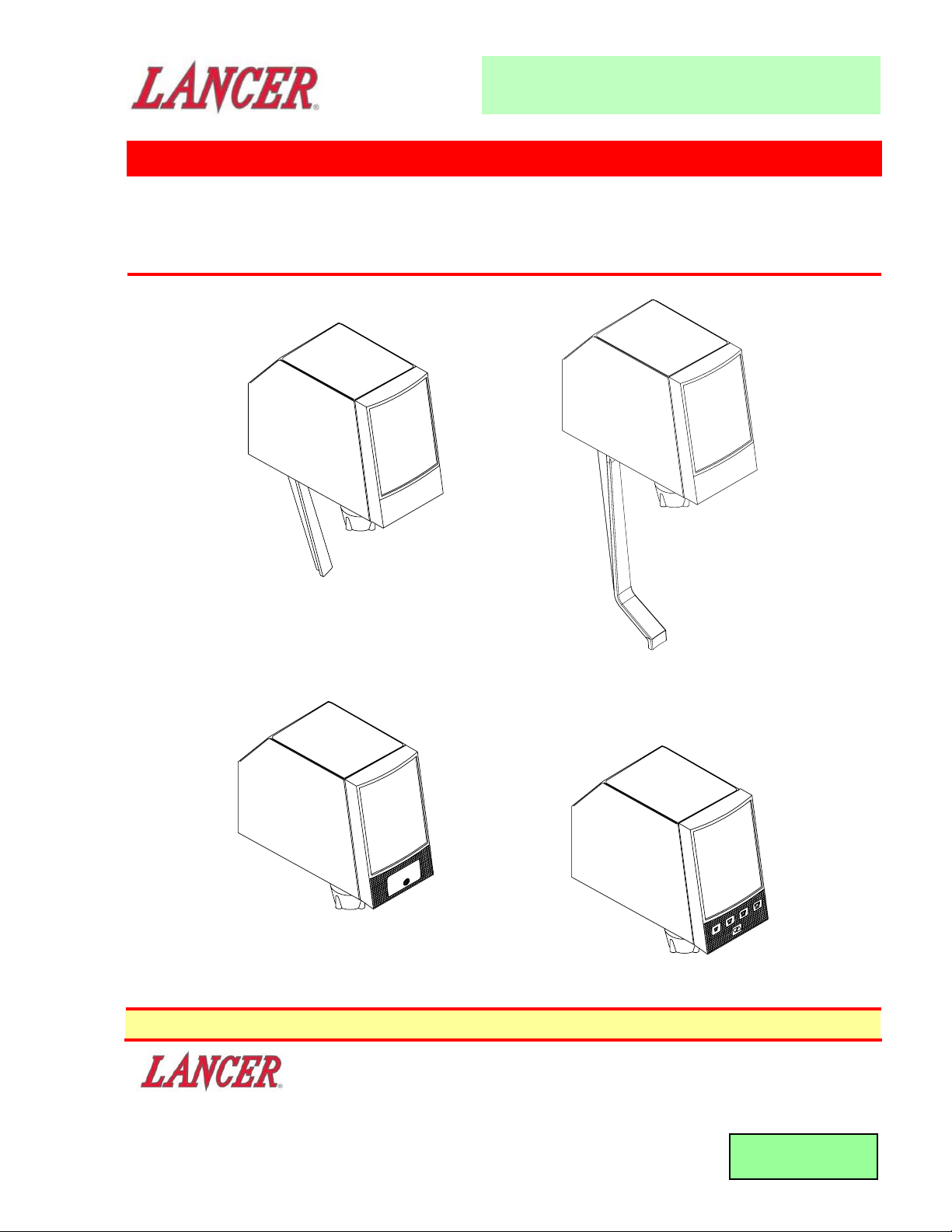
PUSH
Portion Control
Push Button
Standard Lever
Self-Serve Lever
Page 2

i
CONTENTS
CONTENTS.........................................................................................................................................................i
LISTING OF ILLUSTRATIONS...........................................................................................................................i
DESCRIPTION ...................................................................................................................................................1
SPECIFICATIONS..............................................................................................................................................1
MAINTENANCE TOOLS....................................................................................................................................1
1. PRINCIPLE OF OPERATION......................................................................................................................2
2. VOLUMETRIC VALVE CLEANING AND SANITIZING PROCEDURES ....................................................3
3. VALVE SET-UP............................................................................................................................................4
4. SYRUP RESTRICTOR SETTING................................................................................................................4
5. SYRUP PURGE PLUG................................................................................................................................4
6. PROGRAMMER OPERATING PROCEDURES..........................................................................................5
7. PORTION CONTROL PROGRAMMING PROCEDURES ..........................................................................7
8. COVER AND ID PANEL..............................................................................................................................8
9. VALVE .........................................................................................................................................................9
10. LEVER ARM ................................................................................................................................................9
11. NOZZLE/DIFFUSER ..................................................................................................................................10
12. CIRCUIT BOARD ......................................................................................................................................10
13. FLOWMETER ............................................................................................................................................10
14. FLOW WASHER ASSEMBLY ...................................................................................................................11
15. SYRUP REGULATOR PLUG ....................................................................................................................13
16. WATER SOLENOID ACCESS...................................................................................................................14
17. WATER SOLENOID ASSEMBLY..............................................................................................................14
18. SYRUP BODY ACCESS ...........................................................................................................................15
19. SYRUP SOLENOID ACCESS ...................................................................................................................16
20. SYRUP SOLENOID ASSEMBLY ..............................................................................................................17
21. TROUBLESHOOTING...............................................................................................................................18
VOLUMETRIC VALVE PARTS LIST ...............................................................................................................22
LISTING OF ILLUSTRA
TIONS
1. MAIN COMPONENTS .................................................................................................................................2
2. OPERATION DIAGRAM - VALVE ON ........................................................................................................2
3. OPERATION DIAGRAM - VALVE ON ........................................................................................................2
4. OPERATION DIAGRAM - VALVE OFF.......................................................................................................3
5. NOZZLE/DIFFUSER....................................................................................................................................3
6. VALVE CONTROLS ....................................................................................................................................4
7. SYRUP PURGE PLUG................................................................................................................................5
8, HAND HELD PROGRAMMER, PN 52-1420/01..........................................................................................5
9. PORTION CONTROL, CUP BUTTONS, OVERLAY...................................................................................7
10. PORTION CONTROL, CUP BUTTONS, OVERLAY, WITH WATER ..........................................................7
11. RAISED TAB CONFIGURATION ................................................................................................................8
12. REMOVING THE HOUSING .......................................................................................................................8
13. ID PANEL INSTALLATION..........................................................................................................................9
14. LEVER ARM REPLACEMENT....................................................................................................................9
15. NOZZLE/DIFFUSER ..................................................................................................................................10
16. CIRCUIT BOARD CONNECTIONS...........................................................................................................10
17. CIRCUIT BOARD MOUNTING ..................................................................................................................11
18. FLOW METER ACCESS ...........................................................................................................................12
19. FLOW WASHER/SYRUP PLUG ACCESS ...............................................................................................12
20. WATER SOLENOID ACCESS...................................................................................................................13
21. WATER SOLENOID ASSEMBLY..............................................................................................................14
22. SYRUP BODY ACCESS ...........................................................................................................................15
23. SYRUP SOLENOID ACCESS ...................................................................................................................16
24. SYRUP SOLENOID ASSEMBLY ..............................................................................................................17
25. EXPLODED VIEW, VOLUMETRIC VALVE ASSEMBLY ..........................................................................23
MAINTENANCE MANUAL
Volumetric Post-Mix Valve
Page 3

DESCRIPTION
The Volumetric Valve dispenses post-mix beverages accurately over a broad range of pressures and syrup
viscosities. Configurations, from a cup lever to a portion control panel interface, allow the Volumetric Valve
to fit many different applications. The Volumetric Valve mounts to a standard LEV
® back block and utilizes
the same cover as the LEV®.
SPECIFICATIONS
FINISHED DRINK FLOW RATES:
• 3.0 ounces per sec (88.7 ml/sec), Standard
• 2.25 ounces per sec (66.5 ml/sec)
• 1.50 ounces per sec (44.4 ml/sec)
PRESSURE REQUIREMENTS:
Flowing pressure (at the valve)
Minimum Maximum
Water 40 psig 110 psig
(2.8 Kg/cm2) (7.7 Kg/cm2)
Syrup (Sugar) 20 psig 70 psig
(1.4 Kg/cm2) (4.9 Kg/cm2)
Syrup (Diet) 10 psig 70 psig
(0.7 Kg/cm2) (4.9 Kg/cm2)
ELECTRICAL REQUIREMENT:
24 VAC, 50/60 Hz
MOUNTING
Mounts on the same hole pattern with the same mounting screws as the following valves:
Lancer LEV
® Cornelius SF-1 Dole SEV McCann Turbo Flo Jr. Dole FFV
MAINTENANCE TOOLS
When troubleshooting and accessing the Volumetric Valve, the following tools will be needed:
Standard
• #2 Phillips Head Screw Driver
• Flat End Screw Driver
• Dow Corning® 111 Valve Lubricant & Sealant
• Volumetric Valve Hand Held Programmer (Lancer PN 52-1420/02; CCPN 532179)
Optional
• 3/16 inch Hex Socket Driver
• Ohmmeter
1
MAINTENANCE MANUAL
Volumetric Post-Mix Valve
Page 4
1. PRINCIPLE OF OPERATION
1.1 HOW THE SYSTEM WORKS
2
Main Components
Figure 1
A. Three systems in the Volumetric Valve work together to maintain an accurate syrup to water
ratio:
• The circuit board with its computer.
• The water measuring system.
• The syrup injecting system.
B. Set the ratio by using the hand held programmer (Lancer PN 52-1420/02; CCPN 532179).
C. When a customer activates the valve, the water starts flowing to the nozzle. The flow washer
ensures that the water does not flow too fast.
D. The paddle wheel in the flowmeter begins to spin, sending signals to the circuit board (see
Figure 2).
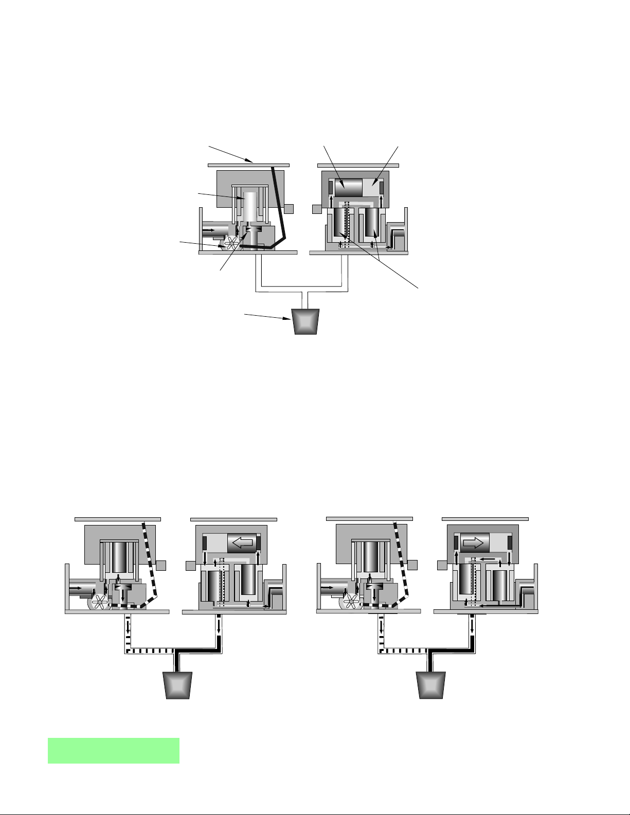
Operation Diagram - Valve ON
Figure 2
Operation Diagram - Valve ON
Figure 3
MAINTENANCE MANUAL
Volumetric Post-Mix Valve
Components:
Circuit Board
Water Syrup
Measuring
System
Water
Solenoid
Flowmeter
Flow Washer
Nozzle
W1
W1
Piston
S1
S1
Syrup Chamber
S2
S2
Injecting
System
Syrup Solenoids
S1
S1
S2
S2
Page 5
E. The computer on the circuit board
monitors the signals and determines
when to precisely inject syrup into the
water stream. The circuit board
energizes one syrup solenoid and then
the other. This alternating action injects a
metered amount of syrup into the water.
This happens seven to eight (7-8) times
a second (see Figures 2 and 3).
F. The circuit board indicates which
solenoid is activated with the LEDs
mounted on the front of the board. The
green LED corresponds to the water
solenoid and the red LEDs correspond to
the syrup solenoids.
3
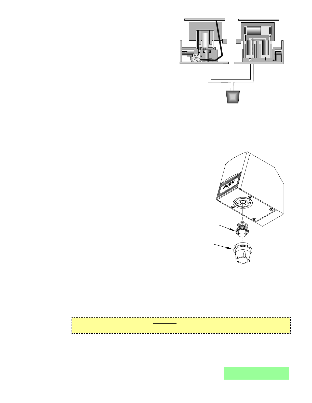
Operation Diagram - Valve OFF
Figure 4
2. VOLUMETRIC VALVE CLEANING AND SANITIZING PROCEDURES
2.1 DAILY NOZZLE/DIFFUSER CLEANING (SEE FIGURE 5)
Use the following procedures to clean the nozzle, and the diffuser assembly, each day:
A. Remove nozzle by twisting it counter-clockwise and
pulling it down.
B. Pull the diffuser assembly down to remove it from the
valve.
C. Wash the nozzle and diffuser with warm water.
D. If needed, apply 111 lubricant to the o-ring on the
diffuser assembly. Then, carefully press it into the
diffuser mounting area on the underside of the valve.
E. Install the nozzle by inserting it into the bottom plate
and twisting it clockwise to lock it in place.
2.2 MONTHLY NOZZLE/DIFFUSER SANITIZING
Use the following procedures to sanitize the nozzle, and
the diffuser assembly, once a month.
A. Cleaning Solution
Prepare a caustic-based (low sudsing, non-perfumed,
and easily rinsed) detergent solution and clean,
potable water at a temperature of 90° to 110°F. The
cleaning solution should be 2% sodium hydroxide.
B. Sanitizing Solution
Nozzle / Diffuser
Figure 5
potable water at a temperature of 90° to 110°F. Any sanitizing solution may be used as long as it is
prepared in accordance with the manufacturer’s written recommendations and safety guidelines, and
provides 50 PPM available chlorine.
C. Cleaning Procedure
CAUTION
BE CAREFUL NOT TO GET SANITIZING SOLUTION ON THE CIRCUIT BOARD.
1. Disconnect power, so the valve will not be inadvertently activated while cleaning.
2. Remove nozzle by twisting it counter-clockwise and pulling it down.
3. Pull the diffuser assembly down to remove it from the valve.
4. Wash the nozzle and diffuser with the cleaning solution.
5. Immerse the nozzle and diffuser in a bath of the sanitizing solution for 15 minutes.
MAINTENANCE MANUAL
Volumetric Post-Mix Valve
Prepare a chlorine solution (less than pH 7.0)
containing 50 PPM available chlorine with clean,
W1
W1
Diffuser Assembly
54-0176/02
(24245)
Nozzle
05-2053
(24246)
NOTE: Part Number in ( ) is a Coca-Cola PN
S1
S1
S2
S2
Page 6
6. While the parts are in the sanitizing
solution, visually inspect around the
nozzle mounting area on the valve
for syrup residue. Using a cloth or
nozzle brush and warm water,
clean this area.
7. Wipe off the dispensing lever and
any other areas that may have
been splashed by syrup.
8. Wearing sanitary gloves, remove,
drain, and air dry the nozzle and
diffuser.
9. Wearing sanitary gloves, carefully
press the diffuser into the mounting
area on the underside of the valve.
10. Wearing sanitary gloves, install the
nozzle by inserting it into the
bottom plate and twisting it
clockwise to lock it in place.
4
MAINTENANCE MANUAL
Volumetric Post-Mix Valve
Valve Controls
Figure 6
11. Connect power and replace cover. Valve is ready for operation.
12. Draw drinks to flush residual sanitizing solution. Taste the beverage to verify that there is
no off taste. If an off taste is found, additional flushing may be required.
2.3 VALVE AND SYSTEM SANITIZING
A. The complete valve and dispenser system must be sanitized during initial installation. Follow
the manufacturer’s instructions when scheduling and conducting dispenser sanitizing. The
valve must be sanitized once every two weeks. The valve may remain on the dispensing tower
during the sanitizing process.
B. For syrup side line priming, and cleaning and sanitization procedures, refer to the Syrup Purge
Plug (Lancer PN 52-1912) in the Valve Set-Up Section.
3. VALVE SET-UP
3.1 The following steps provide an overview of the valve set-up procedures:
A. Mount valve on back block (see Section 9).
B. Verify that power supply is 24 VAC, 50/60 Hz, then connect to valve.
C. Connect water (soda) and syrup supplies. Flowing pressures must meet valve specifications
(see Specifications, Page i).
D. Set ratio and select carbonation. See Section 6 for hand held programmer procedures.
E. Set the syrup restrictor for either diet or sugar syrup (see Section 4).
F. Purge syrup lines using the hand held programmer (see Section 6).
G. Install valve cover, and if necessary, connect ID panel (see Section 8).
H. Activate valve to test dispensing.
4. SYRUP RESTRICTOR SETTING
4.1 SUGAR SYRUP AND DIET SYRUP FROM FIGALS
Restrictor out and down. Syrup restrictor is not in use.
4.2 DIET SYRUP FROM BAG-IN-BOX
Restrictor in and up. Syrup restrictor is in use.
5. SYRUP PURGE PLUG
5.1 The Syrup Purge Plug (PN 52-1912), places the valve in continuous syrup side operation.
5.2 The targeted uses for the purge plug consist of priming the syrup line on an initial Volumetric Valve
install, and for cleaning and sanitization of the syrup side of the dispensing unit.
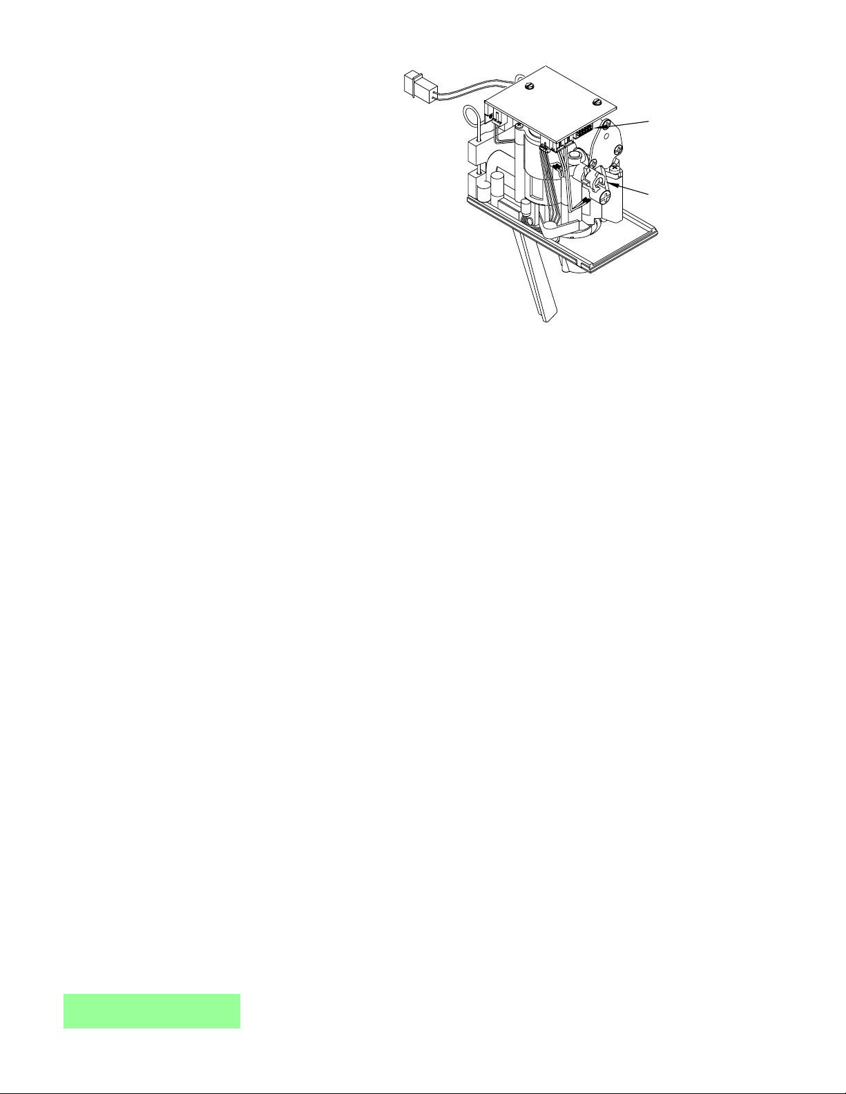
Plug (Programmer,
Portion Control,
Pushbutton, Syrup
Purge Plug)
Syrup Restrictor
Page 7
5.3 Operation of the syrup purge plug is as follows:
CAUTION
THE VALVE CONSUMES 12VA IN A CONTINUOUS SYRUP SIDE OPERATION. WITH A
STANDARD 75VA TRANSFORMER, UP TO SIX (6) VOLUMETRIC VALVES CAN BE OPERATED
IN SYRUP PURGE MODE SIMULTANEOUSLY.
A. Turn off electrical power to all valves.
B. Install syrup purge plugs into the valve or valves to be primed or sanitized. The syrup purge
5
MAINTENANCE MANUAL
Volumetric Post-Mix Valve
plug installs in the ten-pin connector of the Volumetric
Valve circuit board.
C. Turn on electrical power to the valves. At this time, the
syrup side of the valves will begin continuous operation.
D. When through with the priming or sanitization operation,
syrup purge operation can be stopped either of two
ways:
1. Method 1: Turn off electrical power to all valves,
remove syrup purge plugs from the valves. Turn on
electrical power to all valves. Tap valve lever or
push button to ensure proper operation of all valves.
Syrup Purge Plug
Figure 7
2. Method 2: Remove syrup purge plug from the valves while they are in purge operation. In
this case, the valve may continue in the purge mode for up to six (6) seconds after removal
of the plug (this is normal). Tap valve lever or push button to ensure proper operation of all
valves.
5.4 With a standard 75 VA transformer, up to six (6) Volumetric Valves can be operated in syrup purge
mode simultaneously.
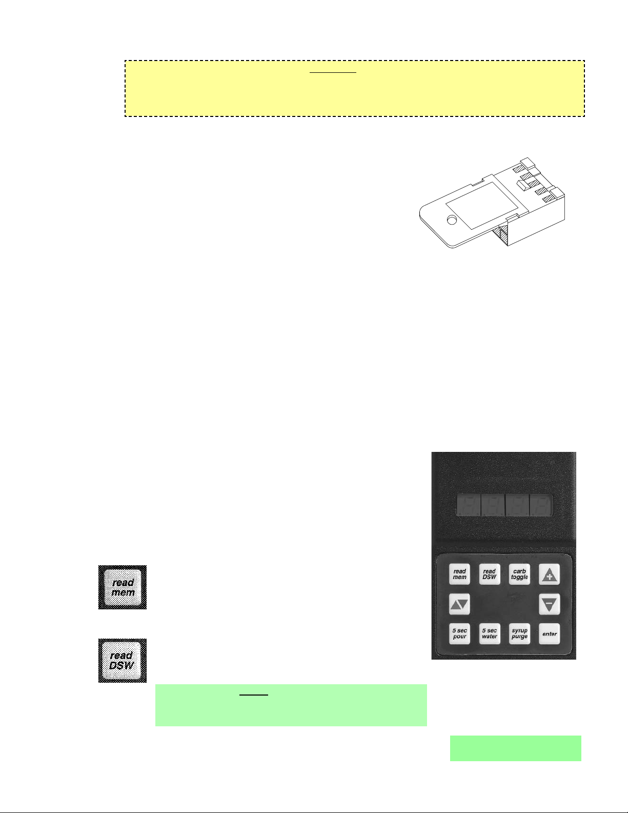
6. PROGRAMMER OPERATING PROCEDURES
6.1 CONNECTING
A. Remove the ID panel from the front of the valve.
B. Insert the programmer's 10-pin connector into the ID Panel plug on the front of the circuit board.
Hand Held Programmer,
Lancer PN 52-1420/02
CCPN 532179
Figure 8
C. When properly connected, the programmer will run a self
diagnostic test. The display will show all "8"s with the
decimal points lighted. After three (3) seconds, the display
indicates the setting of the dip switches.
D. If the programmer does not run its diagnostic test properly,
disconnect it and try plugging it in again. If the programmer
still fails, replace the programmer.
6.2 FUNCTIONS
Read Memory:
Press this button to read and display the current settings
programmed into the valve memory (i.e., S/W revision,
ratio, and carb/non carb settings).
Read Dip Switches:
Press this button to read the dip switch settings.
NOTE
Dip switches were used on some field test valves (see
28-0301, 12/20/95).
SYRUP PURGE
52-1912
Page 8
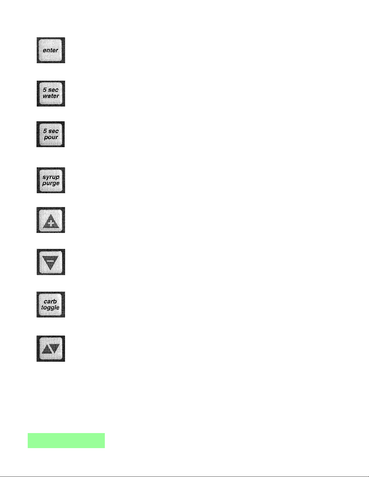
Write Memory:
Press this button to write the programmer’s displayed ratio and carbonation settings into the
valve’s memory.
Timed 5 Second Water:
Press this button to pour water for five (5) seconds. The programmer will display the ratio, the
counts from the flowmeter, the flow rate in oz/sec, and the flow rate in ml/sec.
Timed 5 Second Pour:
Press this button to dispense a five (5) second pour of water and syrup for ratio testing. When
complete, the programmer displays the ratio, carbonation settings, and total Flowmeter
counts.
Syrup Purge:
Press and release to dispense a six (6) second syrup purge. Continue holding to purge syrup
from system.
Ratio + (Plus):
Pressing this button will increase the ratio number on the display.
Ratio - (Minus):
Pressing this button will decrease the ratio number on the display.
Carb Toggle:
Pressing this button will toggle the carbonation setting from carbonated “C” to plain water “n”
(non-carbonated).
Pour/Stop:
Press this button to manually pour a mixed drink. This button will also stop a timed pour.
6.3 SETTING THE RATIO/CARBONATION
A. Connect the programmer to the Valve.
B. Press the “Read Mem” button.
C. Press the “Ratio +” or the “Ratio -” key until the desired ratio is displayed.
D. Verify drink type. Press “Carb Toggle”to select “C” for carbonated or “n” for non-carbonated.
E. Press the “Enter” button to program the valve with the setting on the display
F. Verify Ratio by pressing “Read Mem”.
G. Disconnect the programmer.
6
MAINTENANCE MANUAL
Volumetric Post-Mix Valve
Page 9
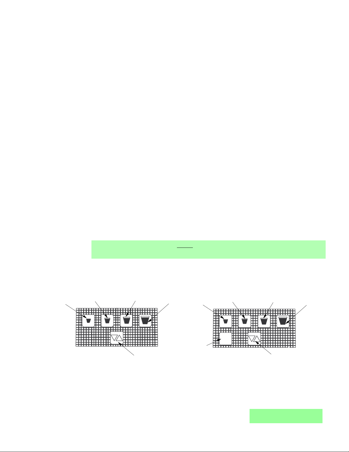
7. PORTION CONTROL PROGRAMMING PROCEDURES
The following procedures describe the operation and programming of portion control ID panels for the
Volumetric Valve.
7.1 OPERATION
A. Cup buttons are Small, Medium, Large, Extra-Large.
B. Press and release the desired cup size. Valve will fill cup as programmed (See below).
C. Pour/Cancel Button
1. Push and release to cancel or stop valve dispensing.
2. Push and hold for continuous pour.
D. Water Button
1. Push and hold for continuous water pour.
2. Valve will dispense carbonated or non-carbonated water, depending on its location on the
dispenser.
7.2 TEACH AND LEARN PORTION CONTROL PROGRAMMING
In this mode, the valve “learns” the steps to fill each cup size, including the top off delay time. When
activated, the valve dispenses the appropriate drink volume. Then, if a top off has been entered, it
will pause for the programmed length of time. Finally, the valve will dispense the correct top off
amount.
A. Initial Install Procedure
1. Simultaneously, press and hold the small cup button and the extra-large cup button
switches on the portion control until the LED light in center of module starts blinking, then
release switches. The blinking LED indicates that the set mode is active.
2. Put desired amount of ice in cup, place cup under valve and push selected size button
(small, medium, large, or extra-large). Hold button in until cup fills to desired portion, then
release button.
3. Top off: If a top off is not needed, go to Step 4. Wait for foam to settle, then actuate button
again to top off.
NOTE
Only one (1) top off is allowed.
4. Repeat steps 2 and 3 for other drink sizes. Go to Step 5 to exit program mode.
5. Press and release pour/stop button to return the portion control to the operational mode.
Blinking LED light will go out.
6. Repeat steps 1 through 5 for remaining valves.
7
MAINTENANCE MANUAL
Volumetric Post-Mix Valve
Portion Control, Cup Buttons, Overlay
Figure 9
Portion Control, Cup Buttons, Overlay, with Water
Figure 10
7.3 TO CHANGE DISPENSE SIZE
Use procedures in the Initial Install Procedure discussed above; it is not necessary to reprogram
every size.
Small
Cup Button
Medium
Cup Button
Large
Cup Button
Extra-Large
Cup Button
Small
Cup Button
Medium
Cup Button
Large
Cup Button
Extra-Large
Cup Button
water
Water
Pour/Stop
Cup Button
Button
Pour/Stop
Cup Button
Page 10

7.4 CALIBRATED CUP PORTION CONTROL PROGRAMMING
In this mode, the valve adds the volume from each programming step to the total drink size. When
activated, the valve dispenses the total drink, without pauses.
A. Simultaneously, press and hold the small and large buttons (see Figures 9 and 10) on the
portion control until the LED light in the center starts blinking, then release switches.
B. Place volume cup under nozzle of valve to be calibrated.
C. Press appropriate size switch and fill volume cup to a point just short of the calibration mark on
the volume cup. The LED will stay lighted constantly while programming an individual cup size.
D. Let foam settle, jog size switch until liquid reaches the calibration mark on the volume cup.
E. Press pour/stop button to end programming for selected cup size. LED will start blinking.
F. To program another cup size, repeat steps B through E, this section (above).
G. To exit the calibrated cup programming mode, press the pour/stop button when the LED is
blinking. If the LED is lighted constantly, press the pour/stop button once to end the cup size
program (LED starts blinking) and again to exit the program mode (LED off).
8. COVER AND ID PANEL
8.1 REMOVAL
8
MAINTENANCE MANUAL
Volumetric Post-Mix Valve
A. ID panel: Slide ID panel up until it detaches from cover.
CAUTION
PULL CAREFULLY, IF WIRES FOR A PUSHBUTTON OR
PORTION CONTROL ARE ATTACHED.
B. ID panel connector (If applicable): The circuit board
connector on the Volumetric Valve has an interlock feature
that acts to keep an ID panel plug or Hand Held
Programmer (HHP) plug properly connected. The interlock
feature consists of a recess in the circuit board connector housing and a raised tab on the
housing plug. See Figure 11, for the raised tab configuration.
When removing the connector, it is important to
hold the housing and not the wires. The housing
easily slides out of the circuit board connector
by placing a very slight downward pressure
onto the housing as it is removed (see
Figure 12).
NOTE
Pulling straight out while holding onto the wires
is not recommended and will likely cause
damage to the valve, ID panel and/or HHP
cable.
C. Cover: Loosen, but do not remove, cover screw.
Pull cover straight up, until it is clear of the valve
body.
NOTE
Push Button ID panel or lever must be connected to run "Syrup Pour" test from dip switches.
Push Button ID panel or lever must be disconnected to use the hand held programmer.
8.2 INSTALLATION
A. Plug the ID panel connector (if applicable) into the front of the circuit board.
B. Slide cover over valve, making certain that wires do not get pinched.
NOTE
If solenoids were replaced or moved, ensure terminal blocks do not interfere with cover. Check
for proper orientation.
Removing the Housing
Figure 12
Raised Tab Configuration
Figure 11
Raised Tab,
Housing Plug
Slight downward pressure here,
while pulling housing straight out
PUSH
Page 11

the pivot axle can be positioned over the slot formed by the valve body and bottom plate.
Release the valve to allow the pivot axle to be seated in the slot.
C. Mount valve in back block.
D. Install ID panel and cover.
9
C. Tighten cover screw.
CAUTION
DO NOT PINCH OR DAMAGE ID PANEL WIRES DURING
INSTALLATION.
D. Align the bottom of the ID panel with the guide slots on
the front of the cover. Slide the ID panel down into place.
NOTE
Attach the ID panel connector before installing cover to
keep wires out of the way.
9. VALVE
9.1 REMOVAL FROM BACK BLOCK
A. Remove cover and ID panel (see Section 8).
B. Turn back block shut-offs to the closed position.
C. Activate the valve (press lever arm or pushbutton) to
relieve pressure.
D. Unplug 24 Volt supply.
E. Raise valve retainer.
NOTE
The retainer cannot be pulled up until the back block
shut-offs are properly closed.
F. Pull the valve off of the back block.
MAINTENANCE MANUAL
Volumetric Post-Mix Valve
PUSH
2
1
PUSH
ID Panel Installation
Figure 13
9.2 MOUNTING ON BACK BLOCK
A. Check o-rings on back block. Replace o-rings, if necessary.
B. Apply 111 Lubricant to o-rings, if necessary.
C. Press valve into the back block.
D. Lower the valve retainer to lock the valve in place.
E. Turn the back block shut-offs to the open position.
F. Connect the 24 Volt supply to the plug on the circuit board.
G. Install cover and ID panel.
10. LEVER ARM
10.1 REMOVAL
A. Remove cover and ID panel (see Section 8).
B. Remove valve from back block (see Section 9).
C. Insert lever arm into bottom plate and
snap pivot axle into back of valve as
shown in Figure 14.
10.2 INSTALLATION
A. With the valve detached
from the back block, insert
the magnet end of the lever
arm into the hole on the
bottom, backside of the
valve.
Lever Arm Replacement
Figure 14
B. Pull the lever arm back while
pushing it into the valve, so
I.D. Panel, Large Pushbutton
Valve with
Cover in Place
Lever Arm
54-0125/01 Shown
(24234 Shown)
NOTE: Part Number in ( ) is a Coca-Cola PN
Page 12

11. NOZZLE/DIFFUSER
11.1 REMOVAL
A. Remove nozzle, by twisting it counter-clockwise and pulling
it in a downward direction (see Figure 15).
B. Remove the diffuser assembly, by pulling it in a downward
direction.
11.2 ASSEMBLY
A. Slide o-ring into the groove on the end of the diffuser
assembly, if necessary.
B. Apply 111 Lubricant to o-ring, as required.
C. Insert diffuser assembly carefully into the underside of the
valve.
D. Install nozzle by inserting it into the bottom plate and
twisting it in a clockwise direction to lock it into place.
12. CIRCUIT BOARD
10
MAINTENANCE MANUAL
Volumetric Post-Mix Valve
Nozzle / Diffuser
Figure 15
12.1 REMOVAL
A. Unplug 24 Volt supply.
B. Use a flat end screw driver to remove each of the screws holding the circuit board in place.
C. Disconnect the solenoids and flowmeter from the circuit board, by pressing each connectors
locking tab and pulling it down out of its socket.
D. Lift the circuit board off of the valve.
D
S
Circuit Board Connections
Figure 16
12.2 INSTALLATION
A. Plug the connector from the rear syrup solenoid
into the receptacle on the underside of the circuit
board near the rear of the valve.
B. Plug the connector from the soda solenoid into
the receptacle located at the front, left corner of
the circuit board.
NOTE
Each solenoid plugs into the nearest circuit
board socket.
C. Plug the connector from the front syrup solenoid
into the receptacle between the soda solenoid
connector and the 10-pin connector on the front
of the circuit board.
D. Plug the 4-pin connector from the flowmeter in
the 4-pin receptacle near the front corner of the
circuit board.
E. Position circuit board on the mounting posts on
top of the syrup body 10-pin connector to the
front.
F. Secure circuit board with two (2) screws.
G. Connect 24 Volt supply.
13. FLOWMETER
13.1 REMOVAL
A. Remove cover and ID panel (see Cover and ID Panel, Section 8).
B. Remove valve from back block (see Valve, Section 9).
C. Remove nozzle/diffuser (see Nozzle/ Diffuser, Section 11).
Diffuser Assembly
54-0176/02
(24245)
Nozzle
05-2053
(24246)
NOTE: Part Number in ( ) is a Coca-Cola PN
Programmer Plug, ID Panel
Front Syrup Solenoid
Plug, Rear Syrup Solenoid
Plug, Flowmeter
Plug, Water Solenoid
Page 13

D. Remove lever arm, if applicable (see Lever
Arm, Section 10).
E. Remove four (4) screws holding the bottom
plate in place.
F. Pull bottom plate off.
CAUTION
CAREFULLY POSITION THE FLOWMETER
SENSOR WIRES, SO THAT THEY ARE NOT
DAMAGED WHILE YOU REMOVE THE
SCREWS.
G. Remove four (4) screws holding the flowmeter
body in place.
H. Carefully pull the flowmeter body and o-ring
off of the valve. Use caution to not pull the
rotor and bearings out of the flowmeter body
as they are snapped into place.
13.2 INSTALLATION
A. Place the o-ring in the groove in the flowmeter
body.
CAUTION
DO NOT PINCH THE FLOWMETER O-RING
DURING INSTALLATION. IT MUST STAY IN THE
GROOVE ON THE FLOWMETER BODY.
11
Screw
Circuit Board
D
S
NOTE: Part Number in ( ) is a Coca-Cola PN
04-0640
(24208)
52-2345/05
(24155)
Circuit Board Mounting
Figure 17
B. Carefully apply a small amount of 111 Lubricant to o-ring, if necessary.
NOTE
Do not get lubricant in the flowmeter.
C. With the wires exiting toward the front of the valve, carefully press the flowmeter sub-assembly
into place on the underside of the valve body. The flat surface of the flowmeter must be flush
against the mounting surface of the valve body.
D. Install four (4) screws to hold the flowmeter in place. Gently position the sensor wires so they
are not pinched or scraped when the screws are installed.
NOTE
The flowmeter screws are 5/8" long, and are longer than the bottom plate screws.
E. Thread the connector attached to the flowmeter sensor wires through hole on the valve body
that is in front of flow washer mounting port (see Figure 18).
F. Place the flowmeter sensor wires around the outside of the flow washer mounting port, so that
they will not interfere with the bottom plate installation.
CAUTION
DO NOT PINCH ANY WIRES WITH THE BOTTOM PLATE.
G. Line up holes on the bottom plate with the screw holes on the underside of the valve body. The
raised sections around the screw holes should fit completely in the counterbores on the bottom
plate.
H. Secure bottom plate in place with four (4) screws.
I. Replace nozzle/diffuser and lever arm (if applicable).
J. Install ID panel and cover.
14. FLOW WASHER ASSEMBLY
14.1 REMOVAL
A. Remove cover and ID panel (see Cover and ID Panel, Section 8).
MAINTENANCE MANUAL
Volumetric Post-Mix Valve
Page 14

B. Remove valve from back block (see Valve, Section 9).
C. Remove nozzle/diffuser (see Nozzle/ Diffuser, Section 11).
D. Remove lever arm, if applicable (see Lever Arm, Section 10).
E. Remove four (4) screws holding the bottom plate in place.
F. Pull bottom plate off.
G. Pull the flow washer assembly out of its port, next to the nozzle mount on the underside of the
valve. The flow washer assembly will be one of the following:
1. Gray, 3.0 ounce/sec product flow.
2. White, 2.25 ounce/sec product flow.
3. Red, 1.5 ounce/sec product flow.
12
MAINTENANCE MANUAL
Volumetric Post-Mix Valve
S
D
Thread
Flow Meter Access
Figure 18
Flow Washer/Syrup Plug Access
Figure 19
D
S
Flowmeter
wires though
Valve Body
at this point
Thread Flowmeter wires though
Valve Body at this point.
Flowmeter
O-Ring
02-0354
Flowmeter
Body
54-0126
Screw
04-0549
(24242)
Bottom Plate
05-0960/01
(24244)
Screw
04-0633
(24209)
Diffuser Assembly
54-0176/02
(24245)
Nozzle
05-2053
(24246)
O-Ring
02-0005
(10050)
NOTE: Part Number in ( ) is a Coca-Cola PN
O-Ring
02-0003
(10049)
Regulator Plug
05-0779/01
(24236)
Flow Washer Assy
54-0192 (Red)
(24237)
Flow Washer Assy
54-0193 (White)
(24238)
Flow Washer Assy
54-0194 (Gray)
(24239)
Bottom Plate
05-0960/01
(24244)
Screw
04-0633
(24209)
O-Ring
02-0005
(10050)
Diffuser Assembly
54-0176/02
(24245)
Nozzle
05-2053
(24246)
NOTE: Part Number in ( ) is a Coca-Cola PN
Page 15

F. Secure bottom plate in place with four (4) screws.
G. Mount valve on back block.
H. Replace nozzle/diffuser and lever arm (if applicable).
I. Install ID panel and cover.
raised sections around the screw holes should fit
completely in the counterbores on the bottom plate.
CAUTION
DO NOT PINCH ANY WIRES DURING INSTALLATION.
F. Secure bottom plate in place with four (4) screws.
G. Mount valve in back block.
H. Replace nozzle/diffuser and lever arm (if
applicable).
I. Install ID panel and cover.
15. SYRUP REGULATOR PLUG
15.1 REMOVAL
A. If the syrup regulator plug or its o-rings need to be
replaced, remove the valve from the back block and
take off the bottom plate.
B. Pull the regulator plug from the regulator port near
the back of the underside of the valve body.
NOTE
There is nothing mounted inside the regulator port.
15.2 INSTALLATION
A. Install o-rings in groove on regulator plug.
B. Apply 111 Lubricant to the o-ring.
C. Insert regulator plug into keyed hole on the
underside of the valve body.
D. Place the flowmeter wires around the outside of the
flow washer assembly, so that they will not interfere
with the bottom plate installation.
CAUTION
DO NOT PINCH ANY WIRES DURING INSTALLATION.
E. Line up holes on the bottom plate with the screw
holes on the underside of the valve body.
13
MAINTENANCE MANUAL
Volumetric Post-Mix Valve
Water Solenoid Access
Figure 20
D
S
Screw
Solenoid
Circuit Board
Screw
Water
Soda Seat
O-Ring
NOTE: Part Number in ( ) is a Coca-Cola PN
02-0005
(10050)
05-0706
(24233)
Assembly
05-0707
(24222)
Retainer
Solenoid
04-0637
(24221)
52-2345/05
04-0640
(24208)
(24155)
14.2 INSTALLATION
A. Install o-rings, if necessary.
B. Apply 111 Lubricant to the o-rings, if necessary.
C. Install the appropriate flow washer assembly into the keyed port on the underside of the valve
body.
NOTE
The flow washer has a flat side and a concave side. The flow washer must be installed with the
concave side facing the small diameter hole in the flow washer retainer.
D. Place the flowmeter wires around the outside of the flow washer mounting port, so that they will
not interfere with the bottom plate installation.
E. Line up holes on the bottom plate with the screw holes on the underside of the valve body. The
CAUTION
THE BOTTOM PLATE HOLDS THE REGULATOR
PLUG AND THE FLOW WASHER RETAINER IN
PLACE. DO NOT PRESSURIZE UNTIL BOTTOM
PLATE IS FIRMLY ATTACHED.
Page 16

16. WATER SOLENOID ACCESS
16.1 REMOVAL
A. Disconnect valve from back block (see Valve, Section 9).
B. Remove circuit board (see Circuit Board, Section 12).
14
MAINTENANCE MANUAL
Volumetric Post-Mix Valve
CAUTION
DO NOT LET THE SOLENOID AND ITS COMPONENTS FALL
WHEN THE RETAINER IS REMOVED. THEY CAN BE
DAMAGED, IF DROPPED.
C. Remove three (3) screws holding the water solenoid
retainer in place. Remove the retainer.
D. Take the water solenoid assembly out of the valve.
16.2 INSTALLATION
If a water seat is already installed, skip to Step H.
A. Put o-ring in groove on water seat.
B. Apply 111 Lubricant to outside edges of o-ring.
CAUTION
USE CARE TO NOT DAMAGE SEATING AREA WHILE
INSERTING WATER SEAT INTO VALVE BODY.
C. Carefully press water seat into the hole at the base of the
water solenoid mounting area in the valve body. Make
certain that the water seat remains completely inserted into
the hole. If it does not, apply more 111 Lubricant to the
o-ring.
D. If necessary, install flow washer (See Flow Washer
Assembly, Section 14).
CAUTION
DO NOT PINCH ANY WIRES DURING INSTALLATION.
Water Solenoid Assembly
Figure 21
F. Secure bottom plate in place with four (4) Screws.
CAUTION
DO NOT GET LUBRICANT ON THE SPRING OR CORE IN THE SOLENOID.
G. Apply 111 Lubricant to the outside edge of o-ring on the water solenoid sub-assembly.
H. Turn valve body over and insert water solenoid sub-assembly into the hole where the water seat
is mounted. Carefully twist the solenoid while pressing it into place, so that the o-ring does not
get pinched. The terminal block on the side of the solenoid must be on the outside edge of the
valve body, turned so that it touches the single solenoid retainer post towards the front of the
valve. Hold the solenoid in place until the retainer is firmly mounted.
I. Place the water solenoid retainer on top of the solenoid and install three (3) screws. The water
solenoid sub-assembly must remain firmly seated during installation to avoid damaging the
o-ring. Tighten each screw a little at a time, so that the retainer stays perpendicular to the water
solenoid.
J. Install the circuit board.
K. Reconnect the valve.
17. WATER SOLENOID ASSEMBLY
17.1 DISASSEMBLY
A. Remove the core/spring assembly from the solenoid.
B. Slide the o-ring off the end of the solenoid.
E. Place the flowmeter wires around the outside of the flow
washer assembly, so that they will not interfere with the
bottom plate installation.
Plug Nut
10-0877/03
O-Ring
02-0538
(10061)
Bonnet,
Solenoid
81-0289
(24224)
Coil
12-0132/02-01
(24225)
Washer,
Solenoid
04-0600
(24226)
O-Ring
02-0109
(17428)
Core/Spring
Assembly
82-1624
(24229)
NOTE: Part Number in ( ) is a Coca-Cola PN
Page 17

J. Pull the syrup down tube restrictor assembly out of the port on the side of the syrup body.
18.2 INSTALLATION
A. If necessary, install an o-ring on either end of the syrup down tube restrictor assembly.
B. Apply 111 Lubricant around each end of the syrup down tube restrictor, if necessary.
C. Insert syrup down tube restrictor assembly into port on the side of the syrup body
sub-assembly.
D. Apply 111 Lubricant to the outside edge of o-ring on the syrup solenoids.
CAUTION
DO NOT GET LUBRICANT ON THE SPRING OR CORE IN THE SOLENOID.
D
S
Screw
C. Lift the solenoid washer off the end of the solenoid.
CAUTION
THE PLUG NUT MAY PULL OUT OF THE COIL, WHEN YOU ARE TRYING TO LOOSEN IT. THE
COIL CAN BE DAMAGED IF IT IS DROPPED.
D. Carefully hold the wire terminal block on the side of the coil while pulling the solenoid bonnet to
loosen the water plug nut. When the water plug nut has been pulled out of the coil enough,
remove it and the bonnet by hand.
17.2 ASSEMBLY
A. Slide o-ring into the groove on the water plug nut.
15
MAINTENANCE MANUAL
Volumetric Post-Mix Valve
B. Slide bonnet over coil.
C. Apply 111 Lubricant to o-ring in plug nut.
D. Press plug nut into top of coil/bonnet assembly.
E. Place solenoid washer on bottom end of the
coil/bonnet assembly.
F. Place o-ring over end of coil extending through the
solenoid washer.
G. Insert the core/spring assembly into the end of the
solenoid assembly.
NOTE
Water and syrup solenoid coils are interchangeable.
18. SYRUP BODY ACCESS
18.1 REMOVAL
A. Remove valve from back block (see Valve, Section 9).
B. Remove circuit board (see Circuit Board, Section 12).
C. Remove nozzle/diffuser (see Nozzle/Diffuser,
Section 11).
D. Remove lever arm, if applicable (see Lever Arm, Section
10).
E. Remove four (4) screws holding the bottom plate in
place.
F. Pull bottom plate off.
G. Remove two (2) screws located at front and rear of
syrup body.
H. Turn valve assembly over and remove the two (2)
screws on the underside of the main body, holding the
syrup body in place.
CAUTION
PARTS OF THE SYRUP SOLENOIDS MAY FALL OUT
WHEN THE SYRUP BODY IS REMOVED.
I. Lift the syrup body subassembly off of the syrup
solenoids.
Syrup Body Access
Figure 22
Circuit Board
52-2345/05
(24155)
Syrup Body
Subassembly
82-1117/01
(24217)
Down Tube
Restrictor
Assembly
54-0190
(24220)
04-0640
(24208)
Screw
04-0549
(24242)
Bottom Plate
05-0960/01
(24244)
Screw
04-0633
(24209)
O-Ring
02-0005
(10050)
Diffuser
Assembly
54-0176/02
(24245)
Nozzle
05-2053
(24246)
NOTE: Part Number in ( ) is a Coca-Cola PN
Screw
04-0637
(24221)
Page 18

E. Rotate the front syrup solenoid until its terminal block rests in groove, towards the syrup down
tube port.
F. Rotate the back syrup solenoid, so that its terminal block rests against the water solenoid
retainer mount.
CAUTION
SYRUP SOLENOIDS MUST BE SEATED AGAINST MAIN BODY. IF SOLENOIDS BECOME
UNSEATED, SEE SYRUP SOLENOID ACCESS, INSTALLATION, SECTION 19.
G. Carefully press the syrup body sub-assembly into place on top of the syrup solenoids. If the
syrup body will not smoothly press into place, then apply more 111 Lubricant to the solenoid
o-rings, so that they will not be pinched.
1. Make certain the syrup down tube restrictor assembly goes into the down tube port on the
valve body.
16
MAINTENANCE MANUAL
Volumetric Post-Mix Valve
D
S
Syrup Solenoid Access
Figure 23
2 Hold the syrup body firmly in place until the
mounting screws are completely installed.
CAUTION
MOUNTING SCREWS MUST BE TIGHT. LOOSE
SCREWS WILL CAUSE LEAKS AND WILL CHANGE
VALVE PERFORMANCE.
H. Install screw at front and rear of syrup body.
I. Install two (2) screws on the underside of the main
body, to secure syrup body.
J. Install circuit board (see Circuit Board, Section 12) and
secure with two (2) screws.
K. Place the flowmeter wires around the outside of the
flow washer assembly, so that they will not interfere
with the bottom plate installation. Connect to circuit
board.
CAUTION
DO NOT PINCH ANY WIRES DURING INSTALLATION.
L. Line up holes on the bottom plate with the screw holes
on the underside of the valve body.
M. Secure bottom plate with four (4) screws.
N. Install nozzle/diffuser
O. Install lever arm, if applicable.
19. SYRUP SOLENOID ACCESS
19.1 REMOVAL
H. Turn valve assembly over and remove the two (2) screws, on the underside of the main body,
holding the syrup body in place.
CAUTION
PARTS OF THE SYRUP SOLENOIDS MAY FALL OUT WHEN THE SYRUP BODY IS REMOVED.
A. Remove valve from back block (see Valve, Section 9).
B. Remove circuit board (see Circuit Board, Section 12).
C. Remove nozzle/diffuser (see Nozzle/ Diffuser, Section
11).
D. Remove lever arm, if applicable (see Lever Arm,
Section 10).
E. Remove four (4) screws holding the bottom plate in
place.
F. Pull bottom plate off.
G. Remove the two (2) screws that hold the syrup body in
place.
Screw
04-0640
(24208)
Screw
04-0459
(24242)
Syrup Body
Subassembly
82-1117/02
(24217)
Syrup Down Tube
Restrictor Assembly
54-0190
(24220)
Bottom Plate
05-0960/01
(24244)
Screw
04-0633
(24209)
O-Ring
02-0005
(10050)
Nozzle
05-2053
(24246)
NOTE: Part Number in ( ) is a Coca-Cola PN
Circuit Board
54-2345/05
(24155)
Syrup
Solenoid
Subassembly
O-Ring
02-0005
(10050)
Screw
04-0637
(24221)
Diffuser
Assembly
54-0176/02
(24245)
Page 19

I. Lift the syrup body off of the syrup solenoids.
J. Lift each syrup solenoid out of the valve.
NOTE
The o-ring mounted underneath the solenoid, may stick to the solenoid when it is removed.
19.2 INSTALLATION
A. Install an o-ring over the port in the bottom of each syrup solenoid mounting area on the main
body. Ensure that o-ring seats to bottom of mounting port.
B. Apply 111 Lubricant to the outside edges of the o-rings.
C. Insert syrup solenoid sub-assembly into the rear mounting area on the main body. Twist the
solenoid while pushing it into place to avoid pinching the o-ring at the bottom of the mounting
area. Turn the solenoid, so that the terminal block rests against the water solenoid retainer post.
D. Insert syrup solenoid sub-assembly into the front mounting area on the main body. Twist the
solenoid while pushing it into place to avoid pinching the o-ring at the bottom of the mounting
area. Turn the solenoid so that the terminal block rests in groove towards, but not over, the
syrup down tube port.
E. Apply 111 Lubricant around each of the o-rings on the syrup down tube.
F. Insert syrup down tube into port on the side of the syrup body sub-assembly.
CAUTION
DO NOT GET LUBRICANT ON THE SPRING OR CORE IN THE SOLENOID.
G. Apply 111 Lubricant to the outside edge of o-ring on the syrup solenoids.
H. Carefully press the syrup body sub-assembly into place on top of the syrup solenoids. If the
syrup body will not smoothly press into place, then apply more 111 Lubricant to the solenoid
17
o-rings, so that they will not be pinched. Make certain the
syrup down tube goes into the down tube port on the valve
body. If the solenoid assembly becomes unseated, remove
solenoid assembly and repeat Steps A through D above. Hold
the syrup body firmly in place until the mounting screws are
completely installed.
I. Install two (2) upper screws located at front and rear of syrup
body.
J. Install two (2) screws on the underside of main body, to
secure the syrup body.
K. Place the flowmeter wires around the outside of the flow
washer assembly, so that they will not interfere with the
bottom plate installation.
CAUTION
DO NOT PINCH ANY WIRES DURING INSTALLATION.
L. Line up holes on the bottom plate with the screw holes on the
underside of the main body.
M. Secure bottom plate in place with four (4) screws.
N. Install nozzle/diffuser
O. Install lever arm, if applicable.
P. Install circuit board (see Circuit Board, Section 12).
20. SYRUP SOLENOID ASSEMBLY
20.1 DISASSEMBLY
A. Remove the core/spring assembly from the solenoid.
B. Slide the o-ring off the end of the solenoid.
C. Lift the solenoid washer off the end of the solenoid.
D. If the o-ring remains in the end of the syrup plug nut or on the
post inside the syrup solenoid mounting area on the main
body, remove it.
Syrup Solenoid Assembly
Figure 24
MAINTENANCE MANUAL
Volumetric Post-Mix Valve
O-Ring
02-0109
(17428)
Coil
12-0132/02-01
(24225)
O-Ring
02-0538
(10061)
Core/Spring
Assembly
82-1624
(24229)
Solenoid
Washer
04-0600
(24226)
Solenoid
Bonnet
81-0289
(24224)
Plug Nut
10-0280/02
(24230)
O-Ring
02-0005
(10050)
NOTE: Part Number in ( ) is a Coca-Cola PN
Page 20

21.1 Drink Ratio A. Syrup restrictor A. Check location of restrictor. A. Position restrictor
Incorrect incorrectly set. Restrictor must be in and up for correctly.
(Weak or diet bag-in-box (BIB) applications,
Strong); directly above the the letter “D” in
Programmer the syrup down tube assembly.
available Restrictor must be down and out
for non-diet drinks, directly below
the letter “S” in the syrup down
tube assembly.
B. Flow washer bad B. Water flow over 2.7 oz/sec on a B. Replace flow washer
(if installed). timed pour. Flow washer installed assembly, or install
correctly. one if needed.
C. Insufficient syrup C. Run syrup purge test on hand held C. Increase dispensing
pressure. programmer. Output syrup should system syrup
be approximately 3 ounces. pressure.
D. Syrup obstructed. D. Incorrect ratio measurement after D. Disassemble syrup side
circuit board replaced. and remove obstruction.
E. Incorrect ratio E. 1. Plug in programmer and press E. 1. Reprogram valve’s
setting in memory. “Read Memory”, and ratio memory by using “+/-
and/or carbonation setting keys, Carb Toggle
incorrect. and Write Memory”.
2. Reprogramming of ratio and/or 2. Replace circuit
carbonation setting does not board.
work.
F. Flowmeter F. All other items above F. Replace flowmeter
malfunctioning. checked. assembly.
21.2 Drink Ratio A. Syrup restrictor A. Check location of restrictor. A. Position restrictor
Incorrect incorrectly set. Restrictor must be in and up for correctly.
(Weak or diet bag-in-box (BIB) applications,
Strong); directly above the the letter “D” in
Programmer the syrup down tube assembly.
unavailable Restrictor must be down and out
for non-diet drinks, directly below
the letter “S” in the syrup down
tube assembly.
(Section 21.2 continued on next page)
CAUTION
THE PLUG NUT MAY PULL OUT OF THE COIL, WHEN YOU ARE TRYING TO LOOSEN IT. THE
COIL CAN BE DAMAGED IF IT IS DROPPED.
E. Carefully hold the wire terminal block on the side of the coil while pulling the solenoid bonnet to
loosen the syrup plug nut. When the syrup plug nut has been pulled out of the coil enough,
remove it and the bonnet by hand.
20.2 ASSEMBLY
A. Slide o-ring into the groove on the syrup plug nut.
B. Slide bonnet over coil.
C. Apply 111 Lubricant to o-ring in plug nut, then press plug nut into top of coil/bonnet assembly.
D. Place solenoid washer on bottom end of coil/bonnet assembly.
E. Place o-ring over end of coil extending through solenoid washer.
F. Insert the core/spring assembly into the end of the solenoid assembly.
NOTE
Water and syrup solenoid coils are interchangeable.
21. TROUBLESHOOTING
Symptom Possible Cause Verification Solution
18
MAINTENANCE MANUAL
Volumetric Post-Mix Valve
Page 21

(Section 21.2 continued from previous page)
B. Flow washer bad B. Water flow over 2.7oz/sec on a B. Replace flow washer
(if installed). timed pour. Flow washer installed assembly, or install
correctly. one if needed.
C. Insufficient syrup C. Run syrup purge test on hand held C. Increase dispensing
pressure. programmer. Output syrup should system syrup pressure.
be approximately three (3) ounces.
D. Syrup obstructed. D. Incorrect ratio measurement after D. Disassemble syrup
circuit board replaced. side and remove
obstruction.
E. Flowmeter E. All other items above checked. E. Replace flowmeter
malfunctioning. assembly.
21.3 Nothing A. 24 Volt supply not A. 1. Check plug to 24 Volt supply. A. 1. Plug in 24 Volt
Dispensed plugged in. Supply.
When Valve 2. Neither green nor red LEDs 2. Key ON/OFF on
Activated light up. dispenser.
B. Mounting Block B. Programmer lights up when B. Open mounting block
shut-offs closed. plugged in. Green LED lights up. shut-offs.
C. Push Button or C. Programmer can activate valve, C. Replace ID panel.
Portion control but not Panel Buttons.
malfunctioning.
D. Circuit Board D. Programmer does not light up and D. Check fuse, or
malfunctioning. 24 Volt supply connected. replace circuit board.
E. Soda and front E. “5 sec water” button on E. Connect soda and
syrup solenoid programmer dispenses small front syrup to correct
wires plugged into amount of syrup. Green and red connectors.
wrong connector. LEDs light up.
F. Water solenoid F. Programmer lights up, but does F. Replace water
malfunctioning. not dispense water with solenoid.
“5 sec water”. Shut-offs open.
Green LED lights up.
G. Water Solenoid G. Rubber poppet in core is swollen G. Replace core.
Core defective. or deformed. Green LED lights up.
H. Circuit board H. A new ratio cannot be entered by H. Replace circuit board.
malfunctioning. programmer.
I. Circuit board I. Circuit board not screwed all the I. Ensure board is
misaligned. Lever way down. Board misaligned with aligned and screw
not making holes and mounting posts. board down all the way.
contact with circuit
board sensor.
21.4 Valve A. Syrup shut-off on A. Coils click when activated by A. Open syrup shut-off
Dispenses back block closed. programmer “syrup purge”. on mounting block.
Water Only Green and red LEDs light up.
B. Out of syrup. B. “Syrup purge” draws no syrup and B. Replace BIB or figal.
shut-off is open.
C. Syrup solenoid C. No clicking sound when “syrup C. Plug in syrup solenoid.
unplugged. purge” activated. Green and red
LEDs light up.
D. Flowmeter D. Flow rate zero (0) after programmer D. Plug in flowmeter
unplugged. “5 sec water” pour. Green LED connector.
lights up.
(Section 21.4 continued on next page)
19
MAINTENANCE MANUAL
Volumetric Post-Mix Valve
Symptom Possible Cause Verification Solution
Page 22

(Section 21.4 continued from previous page)
E. Flowmeter E. Flow rate zero (0) after E. Unplug. Dry connector.
connector wet. programmer “5 sec water” pour. Shake water out of
Circuit board wet. No LEDs plug.
light up.
F. Circuit board F. Programmer does not light up F. Replace circuit board.
malfunctioning. when plugged in.
G. Flowmeter rotor G. Flow rate zero (0) after G. Remove obstruction
obstructed, does programmer “5 sec water” pour. or replace flowmeter.
not turn freely. Green LED lights up.
H. Flowmeter H. Flow rate zero (0) after H. Replace flowmeter
sensor bad. programmer “5 sec water” pour. assembly.
Green LED lights up.
I. Syrup solenoid I. No clicking sound when “syrup I. Replace syrup
bad. purge” activated and coils properly solenoid.
connected. Green and red LEDs
light up.
J. Syrup solenoid J. Rubber poppet in core is swollen J. Replace core.
core is defective. or deformed. Green and red LEDs
light up.
K. Syrup side of K. Coils click when “syrup purge” K. Disassemble syrup
valve obstructed. activated, shut-off is open, and side and remove
syrup supply is full. Green and obstruction.
red LEDs light up.
21.5 Valve Pours A. Lever arm or A. Top end of lever arm does not A. Replace lever arm
On Its Own lever spring return to back of valve. and/or lever spring.
damaged.
B. Push Button/ B. Valve stops, when panel B. Replace panel.
Portion Control unplugged from circuit board.
malfunctioning.
C. Circuit board C. Valve pours with lever arm C. Replace circuit board.
malfunctioning. retracted, or pushbutton or
portion control unplugged.
D. Moisture in plug D. Circuit board covered with water D. Unplug. Dry out
(Push Button, or syrup. connector. Shake
programmer) on water out of plug.
front of circuit
card.
21.6 Valve Pours A. Connectors loose. A. Solenoid, flowmeter, and/or A. Insert connectors until
Erratically pushbutton connectors not locking tabs engage.
plugged into circuit board
completely.
B. Pushbutton B. Valve pours erratically when B. Replace pushbutton.
malfunctioning. pushed.
C. Connectors wet. C. Circuit board covered with water C. Unplug all connectors.
or syrup. Dry out and blow dry.
Shake water out of
plug.
D. Circuit board D. Valve pours erratically after D. Replace circuit board.
malfunctioning. pushbutton replaced and
connections cleaned.
E. Air in lines. E. Hissing sound heard out of E. Continue to pour until
valve. lines are purged of air.
Symptom Possible Cause Verification Solution
20
MAINTENANCE MANUAL
Volumetric Post-Mix Valve
Page 23

21.7 Water Leak A. Screw(s) loose. A. Water solenoid or flowmeter A. Tighten screw(s).
screws turn easily.
B. O-ring seal is B. Water leaks past o-ring, after B. Replace o-ring.
bad. screws have been tightened.
C. Flowmeter body C. Crack visible in flowmeter body. C. Replace flowmeter
is broken. assembly.
D. Debris in water D. Water leaks through nozzle. D. Remove debris from
solenoid. water solenoid.
E. Valve body E. Water continues to leak, after E. Replace valve.
broken. items (above) have been checked.
21.8 Syrup Leak A. Screw(s) loose. A. Syrup body or syrup retainer A. Tighten screw(s) to 9
screws turn easily. inch-pounds.
B. O-ring seal is B. Syrup leaks past o-ring, after B. Replace o-ring.
bad. screws have been tightened.
C. Syrup body is C. Crack visible in syrup body. C. Replace syrup body
cracked. Assembly.
D. Debris in syrup D. Syrup leaks through nozzle. D. Remove debris from
solenoid. Syrup Solenoid.
E. Valve body E. Syrup continues to leak, after E. Replace valve.
broken. items (above) have been
checked.
21.9 Excessive A. Diet restrictor A. Restrictor must be set up and in A. Set correctly.
Foam setting incorrect. for diet bag-in-box (BIB) drinks.
For all other drinks, restrictor
must be set out and sideways.
B. Air in system. B. Hissing sound heard from valve. B. Continue to pour until
air is purged from lines.
C. High flow rate. C. Water flow greater than C. Replace flow washer
2.7oz/sec. assembly, or install flow
washer assembly (if not
previously installed).
NOTES
21
MAINTENANCE MANUAL
Volumetric Post-Mix Valve
Symptom Possible Cause Verification Solution
Page 24

D
S
S
D
22. VOLUMETRIC VALVE ASSEMBLY
22
MAINTENANCE MANUAL
Volumetric Post-Mix Valve
Exploded View, Volumetric Valve
Figure 25
2
48
47
44
37
13
16
16
3
4
5
6
11
15
14
7
37
8
9
8
10
19
20
21
22
23
24
25
26
42
62
26
24
25
23
22
21
11
1
63
66
61
6
5
3
51
12
52
20
16
27
WATER
53
54
SODA
55
PUSH
46
45
49
50
28
17
18
30
31a
43
31b
34a
34b
34c
3
65
64
32
33
36
35
3
16
40
41
16
29
37
39
38
17
56
PUSH
WATER
58
WATER
57
PUSH
SODA
59
60
SODA
Page 25

Volumetric Valve Parts List
Lancer CCUSA
Part Part
Item Number
Description
Number
R 1 52-2345/05 PCB Assy 24155
(formerly 52-1561)
2 04-0640 Screw, 4 - 20 24208
R 3 04-0633/01 Screw, 6 - 19 x 0.437 24209
4 03-0188 Spring, Lever 24210
5 03-0187 Retainer, Syrup 24211
6 02-0221 O-Ring 22363
7 54-0115/01 Body Assy, Meter 24212
Assy, Syrup
8 02-0264 O-Ring 24213
R 9 81-0298 Sleeve, Syrup 1070147
10 81-0347 Piston 24215
R 11 05-0940/02 Retainer, Piston 24216
12 04-0302 Screw 21691
13 54-0175 Tube, Down, Syrup,
Restrictor
R 14 05-1094 Restrictor, Syrup 24219
15 02-0085 O-Ring 10060
16 02-0005 O-Ring 10050
17 04-0637 Screw 24221
18 05-0707 Retainer, Soda, 24222
Solenoid
R 19 10-0877/03 Plug Nut, Soda, 1071045
Solenoid
R 20 02-0538 O-Ring 10061
R 21 81-0289 Bonnet, Sub-assy, 24214
Solenoid
R 22 12-0132/01-01 Coil 24225
23 04-0600 Washer, Solenoid 24226
24 02-0109 O-Ring 17428
R 25 23-1071 Core Assy 1071046
26 03-0180 Spring, Core 24228
R 27 10-0280/02 Plug Nut, Syrup 24230
28 03-0233 Retainer, Valve 24231
R 29 54-0178 Main Body Assy 24232
30 05-0706 Seat, Soda 24233
R 31a 54-0125/01 Lever Arm 24234
R 31b 54-0195 Self-Serve Lever 24235
32 05-0779/01 Plug, Regulator 24236
33 02-0003 O-Ring 10049
34a 54-0192 Flow Washer Assy, 24237
Red, 1.50 Ounces
34b 54-0193 Flow Washer Assy, 24238
White, 2.25 Ounces
34c 54-0194 Flow Washer Assy, 24239
Gray, 3.00 Ounces
R 35 54-0126 Meter Assy
(Includes #36)
R 36 02-0354 O-Ring
37 04-0549 Screw, 6 - 19 X 0.625 24242
R 38* 05-1102 Filler, Plate, Bottom 24243
R 39 05-0960/01 Plate, Bottom 24244
R 40 54-0176/01 Diffuser, Body Assy 24245
R 41 05-2053 Nozzle 24246
R 42 54-0190 Down Tube, 24220
Restrictor Assy
R 43 82-0274 Mounting Block 19810
R 44 05-0266/01 Valve Stem, 12270
Mounting Block
R 45 05-0267 Washer 12286
R 46 02-0047 O-Ring 15175
R 47 04-0269 Screw 19894
R 48 03-0087 Retainer, Valve, 12263
Mounting Block
R 49 05-0265/01 Mounting Block 12189
R 50 02-0126 O-Ring 10706
R 51 54-0029/02 Cover Sub-assy 23984
R 52 05-0287/02 ID Panel 21432
R 53 52-1571 ID Panel, 24251
Water Button
R 54 52-1572 ID Panel, 24252
Soda Button
R 55 52-1399 ID Panel, 24253
Push Button
R 56 52-1573 ID Panel, 24254
Push Button, Water
R 57 52-1574 ID Panel, 24255
Push Button, Soda
R 58 52-1575/02 ID Panel, 24256
Portion Control,
R 59 52-1576/02 ID Panel, 24257
Portion Control,
Water
R 60 52-1577/02 ID Panel, 24258
Portion Control,
Soda
R 61 82-1117/02 Meter Assy, Syrup 24217
R 62 82-1624 Core/Spring Assy 24229
(Includes Items 25
and 26)
R 63 05-1187 Cover, 1071044
Programmer Plug
R 64 52-2491 Harness Assy,
Syrup Purge
R 65 05-1958 Holder. Purge Switch,
Volumetric Valve
R 66 12-0348 Fuse, 5 Amp, 5X15, 1070729
Fast Acting
R-- 52-1420/02 Hand Held 532179
Programmer Assy
* Model 150P - Pushbutton only
R in margin indicates change or revision
22. VOLUMETRIC VALVE ASSEMBLY (CONTINUED)
23
MAINTENANCE MANUAL
Volumetric Post-Mix Valve
Lancer CCUSA
Part Part
Item Number Description Number
Page 26

NOTES
24
MAINTENANCE MANUAL
Volumetric Post-Mix Valve
Please refer to the Lancer web site (www.lancercorp.com) for
information relating to Lancer Installation and Service Manuals,
Instruction Sheets, Technical Bulletins, Service Bulletins, etc.
Page 27

25
MAINTENANCE MANUAL
Volumetric Post-Mix Valve
Directory of USA - Canada Offices,
International Offices, and Authorized Distributors
(Continued)
(Continued from previous page)
Pell SudAmerica - Ecuador
Lancer Sales Company
Contact: Luciano Lopez
Sector Las Acacias
Luis De Beethoven #958
Y Capitan Rafael Ramos
Quito, Ecuador
Phone: 593-22-401-598, 400-937, 406-418
FAX: 593-22-400-535
e-mail: Llopez@ecnet.ec
Lancer Authorized Distributors
Eximport & Barter Co. - Caribbean
2101 S.W. 56th Terrace
Hollywood, FL 33023 USA
Phone: (954) 967-9999
FAX: (954) 967-9900
e-mail: edbrandao@aol.com
PromoVen, S.A. - Argentina
Contact: Rafael Mendoza
Juncal 858 - Piso 3 Depto. “L”
(1062) Buenos Aires
Argentina
Phone: (54.11)4394.7654
FAX: (54.11)4394.1193
e-mail: promoven@customw.com.ar
Bras Sulamericana LTDA. - Brasil
Contact: Fabio Queiroz
Rua. Dr. Ladislau Retti, 1400
Parque Alexandre
Cotia Sao Paulo - Brasil
CEP: 06714-150
Phone: 55-11-4612-1122
FAX: 55-11-4612-2219
e-mail: fabio.queiroz@bras.com.br
Lancer Chile Ltda. - Chile
Contact: Heriberto Concha
Vicuna Mackenna 3019, San Joaquin
Santiago, Chile
Phone: 56-2-552-1657
FAX: 56-2-552-1961
e-mail: chocha@lancer.tie.cl
Lancer Pacific
International Sales
6655 Lancer Blvd.
San Antonio, TX 78219
Phone: (210) 310-7000
FAX: (210) 310-7242
1-800-729-1500
e-mail: asia@lancercorp.com
Australia
Lancer Pacific Pty Ltd
5 Toogood Avenue
Beverley 5009
South Australia
Phone: 61-8-8268-1388
FAX: 61-8-8268-1978
e-mail: ian-lunniss@lancer-pacific.com.au
(General Manager, Lancer Pacific)
steve-sotiriou@lancer-pacific.com.au
(for Fountain)
fiore-alvaro@lancer-pacific.com.au
(for Beer)
Lancer Pacific Pty Ltd
7 Slough Avenue
Silverwater 2128
New South Wales
Australia
Phone: 61-2-9648-6840
FAX: 61-2-9648-6850
e-mail: neild-mcintosh@lancer-pacific.com.au
(Managing Director)
john-frize@lancer-pacific.com.au
(NSW State Manager)
Lancer Pacific Pty Ltd
55 Keele Street
Collingwood 3066
Victoria
Australia
Phone: 61-3-8415-1920
FAX: 61-3-8415-1929
e-mail: glenn-blakiston@lancer-pacific.com.au
Lancer Pacific Pty Ltd
Unit 31, 284 Musgrave Drive
Coopers Plains 4108
Queensland
Australia
Phone: 61-7-3274-5700
FAX: 61-7-3875-1805
e-mail: brett-thomson@lancer-pacific.com.au
New Zealand
Lancer Pacific Ltd
9 O’Rorke Street
Onehunga, Auckland
New Zealand
Phone: 64-9-634-3612
Mobile Phone: 64-21-745-389
FAX: 64-9-634-1472
e-mail: mike-peffers@lancer-pacific.com.au
andrew-nixon@lancer-pacific.com.au
Lancer Asia
Hong Kong
1001 Technology Plaza
651 King’s Road
North Point
Hong Kong
Patrick Co - Area Manager - Asia
Phone: 852-2214-9195
Rob Burdock - Senior Director - Asia
Phone: 852-2214-9196
FAX: 852-2214-9448
e-mail: rob-burdock@lancer-asia.com
patrickco@lancer-asia.com
Lancer Authorized Distributors
Shanghai Freser International Co Ltd. China
1856, Hu Tai Road
Shanghai, 200436, China
Phone: 86-21-5650-3555
FAX: 86-21-5650-2666
e-mail: daniel@freser.com.cn
Freser (HK) Company Ltd - Hong Kong
Flat A, 24/F., Houston Industrial Bldg.
32-40 Wang Lung Street
Tsuen Wan, N. T., Hong Kong
Phone: 852-2408-2595
FAX: 852-2408-2605
e-mail: freserhk@netvigator.com
P.T. Dikarunia Sejahtera - Indonesia
JI. Gelong Baru Tengah #1A, Tomang
Jakarta, Barat 11440, Indonesia
Phone: 62-21-5694-3242
62-21-5437-2534
FAX: 62-21-5694-3242
e-mail: dikarunia@cbn.net.id
Hayakawa Sanki - Japan
Hayakawa Sanki, Inc.
1-13-13, Kayaba-cho
Nihonbashi, Chuo-ku
Tokyo, 103-0025
Japan
Phone: 03-5651-1481
FAX: 03-5651-1445
e-mail: SANKI10217@aol.com
Tahoe Corporation - Korea
Tahoe Corporation
2FL, 835-66 Yocksam-dong
Kangnam-Ku
Seoul, Korea
Phone: 82-2-557-5612, -5614
FAX: 82-2-557-5615
e-mail: tahoepark@empal.com
Freser (MALAYSIA) SDN. BHD. - Malaysia
No. 31, Jalan TPP 5/13, Taman
Perindustrian Puchong, Seksyen 5,
47100 Puchong, Selangor, Malaysia
Phone: 60-3-8061-6666
FAX: 60-3-8062-1007
e-mail: freser@tm.net.my
R.B.P. Industrial Sales Inc - Philippines
Unit 20, Facilities Centre Bldg.
548 Shaw Blvd
Mandaluyong City, Philippines
Phone: 632-531-1215/1221/1289
FAX: 632-531-1271
e-mail: rbpsales@info.com.ph
Freser (S) Pte Ltd - Singapore
Blk 998 Toa Payoh North
#04-12/14
Singapore 318993
Phone: 65-6352-0943
FAX: 65-6352-8594
e-mail: fresersin@pacific.net.sg
Freser International Corporation - Taiwan
No. 76, Gui-Sui Street
Taipei 103, Taiwan R.O.C.
Phone: 886-2-2553-1555
FAX: 886-2-2553-2742
e-mail: herman@intl.freser.com.tw
Freser Makasan International Co., Ltd Thailand
Freser Makasan International Co., LTD.
Navanakorn Industrial Estate Zone 4
95/3 Moo 13, Klongnung, Klongluang
Patumthani 12120, Thailand
Phone: 662 520-3457 (Automatic, 7 lines)
FAX: 662 529-3840
e-mail: komsan@makasan.co.th
Lancer - Indian Sub-Continent
India
Shabbir Shafiqui - Area Manager
India and Sub-Continent
B-7, Pannalal Silk Mill Compounds
78, LBS Marg, Bhandup (W)
Mumbai 400-078, India
Phone: 91-22-2561-6665
Cel No.: 91-98-2029-5252
FAX: 91-22-5637-4018
e-mail: shafiquis@vsnl.com
Lancer Authorized Distributors
Western Refrigeration Ltd - India
B-7, Pannalal Silk Mill Compounds
78 L.B.S. Marg, Bhandup (W)
Mumbai 400-078, India
Phone: 91-22-2561-6665
FAX: 91-22-2562-2257
e-mail: western@bom5.vsnl.net.in
Bengal Marketing Company - Bangladesh
Skylark Point (6th Floor)
Room #G-2
24/A Bijoy Nagar,
Dhaka-1000, Bangladesh
Phone: 880-2-934-2987
FAX: 880-2-935-0127
e-mail: bmc@dhaka.agni.com
Dynamic Equipment - Pakistan
Dynamic Equipment and Controls (Pvt.) Ltd.
F-1/23, Canal Cottages, Block-D.
New Muslim Town.
Lahore. Pakistan.
Phone: 0092-42-583-6737
0092-42-583-6787
FAX: 0092-42-586-7924
e-mail: info@dynamic-eqpt.com.pk
m.ateeq@dynamic-eqpt.com.pk
Page 28

26
MAINTENANCE MANUAL
Volumetric Post-Mix Valve
Directory of USA - Canada Offices,
International Offices, and Authorized Distributors
Corporate Office
6655 Lancer Blvd. • San Antonio, Texas 78219 • 210-310-7000 • 1-800-729-1500 • FAX 210-310-7250
Lancer USA
Manufacturing LocationsFoster Road
Foster Road Facilities
6655 Lancer Blvd
San Antonio, TX 78219
Phone: (210) 310-7000
MFG FAX: (210) 310-7088
ENG FAX: (210) 310-7096
ACCT FAX: (210) 310-7091
PURCH FAX: (210) 310-7094
Lancer FBD
5620 Business Park
San Antonio, TX 78218
Phone: (210) 666-0544
FAX: (210) 666-2044
Lancer Ice Link
6655 Lancer Blvd
San Antonio, TX 78219
Phone: (210) 310-7174
FAX: (210) 310-7245
Remanufacturing
6655 Lancer Blvd
San Antonio, TX 78219
Phone: (210) 310-7256
FAX: (210) 310-7261
1-800-729-1550
Lancer North America
USA - Canada Sales
6655 Lancer Blvd.
San Antonio, TX 78219
Phone: (210) 310-7000
SALES FAX: (210) 310-7245
CUSTOMER SERVICE FAX: (210) 310-7250
1-800-729-1500
Georgia Office
1125 Northmeadow Parkway, Suite 116
Roswell, GA 30076
Phone: (770) 343-8828
FAX: (770) 475-8646
1-800-729-1750
Lancer Authorized Distributors
Advanced Beverage Solutions (ABS)
100 N. Gary Avenue, Suite C
Roselle, IL 60172
Phone: (847) 524-1707
(877) 814-2271
FAX: (847) 524-1710
www.absone.com
Bevco
6900 Camille Avenue
Oklahoma City, OK 73149
Phone: (405) 672-7770
FAX: (405) 672-7443
e-mail: info@bevcoinc.com
Joe Kirwan Company
119 White Oak Lane
Old Bridge, NJ 08857
Phone: (732) 679-1900
FAX: (732) 679-9236
e-mail: sales@jkirwan.com
L & M Beverage Equipment Co. Inc.
12510 Santa Fe Trail Drive
Lenexa, KS 66215
Phone: (913) 888-8988
FAX: (913) 888-9137
e-mail: L7mco@aol.com
(Update #50 - as of May 13, 2004)
Ernest F. Mariani Company
614 West 600 South
Salt Lake City, UT 84104
Phone: (801) 359-3744
FAX: (801) 531-9615
e-mail: febell@efmco.com, or
clay@efmco.com
Mark Powers & Company, Inc.
P.O. Box 72
1821 Henry Street
Guntersville, AL 35976
Phone: (256) 582-6620
FAX: (256) 582-8533
e-mail: sales@markpowers-and-company.com
Maurer Supply, Inc.
843 Rainier Avenue South
Seattle, WA 98144
Phone: (206) 323-8640
FAX: (206) 323-9286
e-mail: maurersupply@qwest.net
Simgo Ltd.
5122 Timberlea Blvd.
Mississauga, Ontario L4W 2S5
Canada
Phone: 905-602-5800
FAX: 905-602-5804
e-mail: simgo@simgo.com
Simgo (B.C.) Ltd.
16-8125 - 130th Street
Surrey, B.C. V3W 7X4
Canada
Phone: 604-590-4022
FAX: 604-590-1601
Lancer Europe
Belgium - European Central Office
Lancer Europe, S.A.
Mechelsesteenweg 592
B-1930 Zaventem
Belgium
Phone: 32-2-755-2390
FAX: 32-2-755-2399
e-mail: lancer.europe@glo.be
England
Managing Director
Contact: Paul Haskayne
Lancer G.B. Llp.
Unit 9 Prosperity Court, Midpoint 18
Middlewich CW10 OGD
Cheshire, United Kingdom.
Phone: 441606837711
FAX: +441606832705
e-mail: paul-haskayne@lancer-pacific.com.au
17 Bembridge Gardens
Ruislip, Middlesex
HA4 7ER, England
Phone: 44-1895672667
FAX: 44-1895637537
e-mail: court4lancer@msn.com
Hungary
H-2100 Gödöllõ
Isaszegi út 67
Hungary
Phone: 36-28-417-179
FAX: 36-28416-881
e-mail: bodolai@compuserve.com
Lancer Authorized Distributors
Complete Beverage Services, Ltd.
Republic of Ireland and Northern Ireland
Gortrush Industrial Estate
Omagh County Tyrone
Northern Ireland
Office: 44-1662 250 008
FAX: 44-1662-252-991
Provisiona, S.L. - Spain
Avda. Concha Espina 8
28036 Madrid Spain
Phone: 34-91-564 6900
FAX: 34-91-564 3065
e-mail: jmorales@bevserv.com
Lancer Russia
Lancer International Sales, Inc.
Representation Office
Kashirskoe shosse, 65 (1), Office 505
Moscow 115583 Russia
Mail: Moscow, 115551, Mail Box #2, Russia
Mobile Phone: 7-095-991-7778
Office Phone: 7-095-727-4063
Office FAX: 7-095-727-4064
e-mail: vdemkin@ktv.ru
lancer@online.ru
Lancer Middle East / Africa
Elsayed Moniem - Technical Manager
Lancer Middle East/Africa
7 Mubarak Street
East Ain Shams 11311
Cairo, Egypt
Phone/FAX: 2-02-49-35-395
Mobile Phone (GSM): 2-010-500-4007
e-mail: elsayed_lancer@msn.com
Lancer Authorized Distributor
DispenseTech - South Africa
P.O. Box 17495
Sunward Park, 1470
South Africa
Phone: 27-11-397-7455
FAX: 27-11-397-7648
e-mail: david@dispensetech.co.za
Lancer Latin America
Latin America Sales
6655 Lancer Blvd.
San Antonio, TX 78219
Phone: (210) 310-7000
FAX: (210) 310-7245
1-800-729-1500
e-mail: latinamerica@lancercorp.com
Lancer de México, S.A. de C.V.
Contact: Gerardo Canales
Calle Lerdo De Tejada #544 PTE.
Col. Las Villas
San Nicolas De Los Garza, N.L.
Monterrey, N. L., México C.P. 66422
Phone: (52)-81-83-52-85-32
Phone: (52)-81-83-52-85-34
Phone: (52)-81-83-52-53-60
FAX: (52)-81-83-32-54-10
e-mail: direccion@lancer.com.mx
Lancer de México, S.A. de C.V.
Branch Office, Mexico City
Contact: Carlos Lopez
Lancer de Mexico S.A. de C.V.
Sucursal Mexico D.F.
Calle: Centeotl No. 112
Colonia: La Preciosa
Delegacion: Azcapotzalco
Mexico D.F. C.P. 02460
Phone: (52)-55-53-53-89-28
Phone: (52)-55-53-53-89-26
Phone: (52)-55-53-53-88-60
Phone: (52)-55-53-53-88-21
FAX: (52)-55-53-52-46-30
e-mail: carlos.lopez@lancer.com.mx
(Continued on reverse)
 Loading...