

Page 1
REV. 10/20/00
P.N. 28-0471
This manual is an initial issue.
INSTALLATION AND SERVICE MANUAL
FOR
LANCER KOOL LINK
BEER DISPENSER
FAX ENGINEERING: • 210-310-7096
"Lancer" is the registered trademark of Lancer • Copyright — 2000 by Lancer, all rights reserved.
SPECIFICATIONS
LANCER KL-10 PN 85-5012, 115V/60HZ
PN 85-5022, 230V/50HZ
DIMENSIONS
Width 20 Inches (508 mm)
Depth 21 Inches (533 mm)
Height (with Casters) 40 1/4 Inches (1022 mm)
WEIGHT
Shipping 160 Pounds (73 kg)
Empty 152 Pounds (69 kg)
Operating 312 Pounds (142 kg)
REFRIGERANT 16 Ounces (454 g)
ICE BANK WEIGHT 55 Pounds (25 kg)
WATER BATH CAPACITY 19 Gallons (72 L)
COMPRESSOR Tecumseh, 1/3 HP
CAPACITY [@ 20°F (-6.7°C)] 625 Watts - 2133 BTUs/hour
AGITATOR MOTOR 90 Watts, 2600 RPM
CONDENSER FAN MOTOR 35 Watt
ICE BANK CONTROL Lancer Electronic
AVAILABLE IN 115V/60Hz OR 230V/50Hz
DRINK CAPACITY
90°F (32°C) Ambient, 75°F (24°C) Product
Continuous (one ounce/second) - 350 12 ounce drinks under 40°F (4°C)
Two 12 ounce drinks per minute - 875 12 ounce drinks under 40°F (4°C)
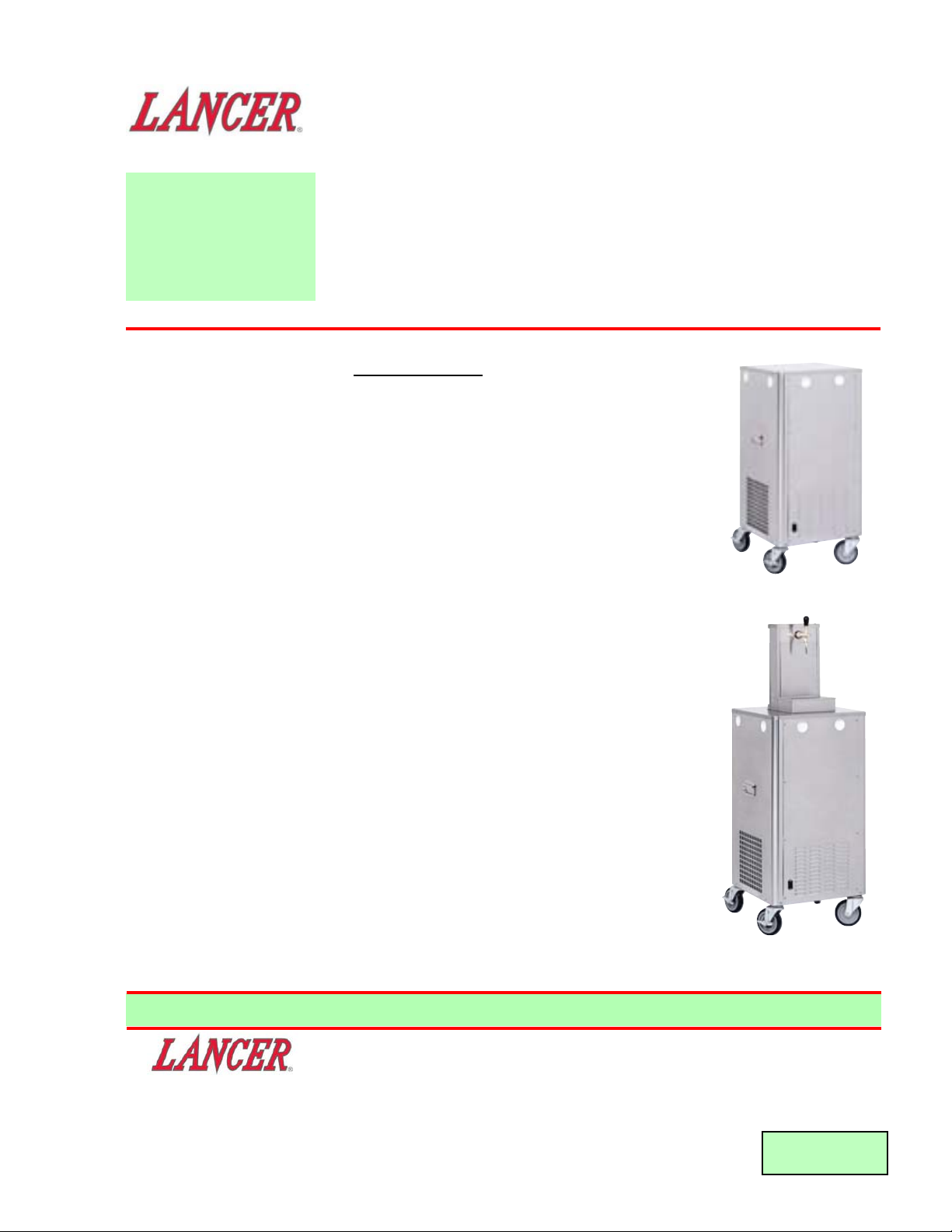
KL-10 Remote
KL-10 Remote with
Single Valve Tower
Please refer to the Lancer web
site (www.lancercorp.com)
for information relating to
Lancer Installation and
Service Manuals, Instruction
Sheets, Technical Bulletins,
Service Bulletins, etc.
6655 LANCER BLVD. • SAN ANTONIO, TEXAS 78219 USA • (210) 310-7000
FAX SALES
• NORTH AMERICA – 210-310-7245 • INTERNATIONAL SALES – 210-310-7242 • CUSTOMER SERVICE – 210-310-7242 •
• LATIN AMERICA – 210-524-9567 / 210-310-7245 • EUROPE – 32-2-755-2399 • PACIFIC – 61-8-8268-1978 •
Page 2
i
TABLE OF CONTENTS
SPECIFICATIONS KL-10 ..........................................................................................................................Cover
TABLE OF CONTENTS ......................................................................................................................................i
PRINCIPLE OF OPERATION .............................................................................................................................i
1. INSTALLATION ...........................................................................................................................................1
1.1 RECEIVING........................................................................................................................................1
1.2 UNPACKING ......................................................................................................................................1
1.3 UNPACKING INSTALLATION KITS (IF SUPPLIED)..........................................................................1
1.4 SELECTING A LOCATION.................................................................................................................1
1.5 CONNECTING TO PRODUCT SUPPLY ...........................................................................................1
1.6 FILLING THE UNIT WITH WATER ....................................................................................................1
1.7 CONNECTING TO ELECTRICAL POWER .......................................................................................1
2. SCHEDULED MAINTENANCE ...................................................................................................................2
2.1 WEEKLY.............................................................................................................................................2
2.2 EVERY SIX MONTHS........................................................................................................................2
2.3 EVERY TWELVE MONTHS ...............................................................................................................2
3. CLEANING & SANITIZING ICE BANK SYSTEMS ....................................................................................2
3.1 GENERAL GUIDELINES....................................................................................................................2
3.2 CLEANING PROCEDURES...............................................................................................................2
4. TROUBLE SHOOTING - REFRIGERATION...............................................................................................3
5. TROUBLE SHOOTING - PRODUCT ..........................................................................................................4
6. ILLUSTRATIONS, PARTS LISTINGS, AND WIRING DIAGRAMS ............................................................6
6.1 INSTALLATION DIAGRAM.................................................................................................................6
6.2 WIRING DIAGRAM, PN 06-2352.......................................................................................................7
6.3 PARTS LISTING.................................................................................................................................8
PRINCIPLE OF OPERATION
ICE BANK COOLERS
Lancer ice bank beer coolers utilize a water bath with an immersed copper tube evaporator which forms a solid
bank of ice around the evaporator coil.
Immersed in this water are two stainless steel beer coils through which the beer is pushed by CO
2 pressure.
As the beer travels through the stainless steel coil it is cooled by the cold water bath. An agitator or optional
agitator/pump keeps the water moving, washing the cold water over the ice bank and over the beer coils.
An ice bank thickness control starts and stops the refrigeration system to maintain the ice bank. The machine
should be left on at all times as the ice bank control will cycle the compressor to maintain the ice bank to the
required thickness.
The ice bank cooler will dispense beer between 1°C - 4.5°C, with an incoming beer temperature of 28°C up to
the stated capacity of the machine. The colder the kegs, the higher the capacity of the machine.
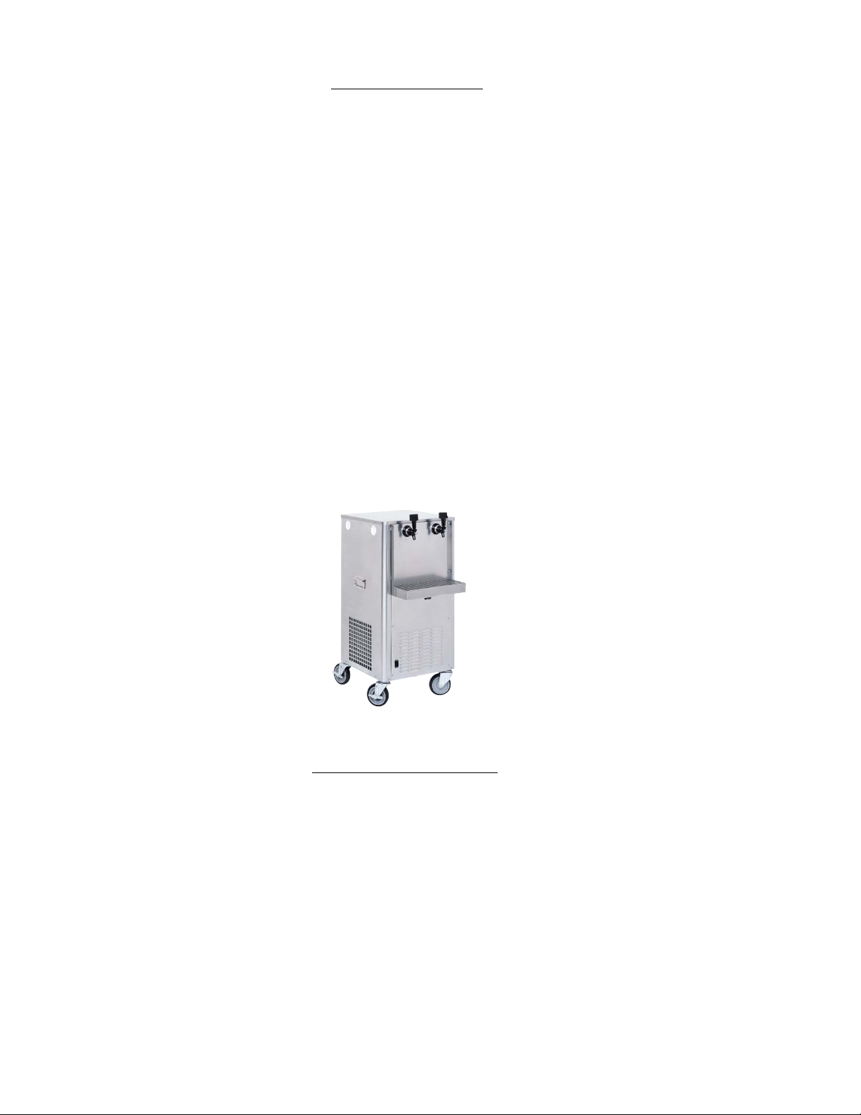
KL-10 Remote with Optional Valve
Plate, Cup Rest, and Drip Tray
Page 3

1
1. INSTALLATION
1.1 RECEIVING
A. Each unit is tested and thoroughly inspected before shipment. At time of shipment the carrier
accepts the unit and any claim for damages must be made with the carrier. Upon receiving the
units from the delivering carrier, carefully inspect the carton for visible indication of damage. If
damage exists have the carrier note it on the bill of lading and file a claim with the carrier.
1.2 UNPACKING
A. Carefully unpack the dispenser from the shipping carton.
1.3 UNPACKING INSTALLATION KITS (IF SUPPLIED)
A. Inspect kits for concealed damage and if evident notify delivering carrier and file a claim against
it.
B. Each kit contains a list and an assembly drawing showing the correct assembly of the parts.
1.4 SELECTING A LOCATION
W
ARNING
FAILURE TO MAINTAIN THE SPECIFIED CLEARANCE WILL CAUSE THE COMPRESSOR TO
OVERHEAT AND WILL RESULT IN COMPRESSOR FAILURE.
All refrigeration equipment should be installed to provide adequate ventilation and ease of service.
A. Allow at least six (6) inches around the machine to enable adequate airflow (integral machine
only). The chiller should be installed so that it can be pulled out to check the machine and
agitator without disconnecting any lines.
B. Install on a flat, level surface with the dispense point as close as possible to the machine, for
example directly above is ideal. Kegs should be as close as practical to the machine, without
hot air from refrigeration equipment, dishwashers, ovens, etc. warming the kegs or lines. Keep
the lines from the keg to the machine as short as practical, while still allowing easy tapping of
kegs.
C. A 10 to 15 amp power outlet should be located within nine (9) feet [approximately one (1) meter]
of the machine. A water supply for filling and cleaning of the ice bath and beer system would
be an advantage, but not essential. CO2 supply should be located close by. A waste pipe to
enable connection of the overflow from the machine, is not essential, but certainly makes a
better installation and is a lot easier for draining the water from the ice bath.
1.5 CONNECTING TO PRODUCT SUPPLY
A. Connect the product supply lines from the keg to the cooler and cooler to the dispense point
(see installation diagram).
B. If water recirculation lines are used to chill python or fonts, connect water recirculation lines to
appropriate ports on the agitator pump.
C. Check all connections for leaks.
1.6 FILLING THE UNIT WITH WATER
A. After installing the chiller as described above, fill the ice bath with clean water until level
reaches the overflow.
1.7 CONNECTING TO ELECTRICAL POWER
WARNING
THIS UNIT MUST BE PROPERLY ELECTRICALLY GROUNDED (EARTHED) TO AVOID
POSSIBLE FATAL ELECTRICAL SHOCK OR SERIOUS INJURY TO THE OPERATOR. THE
POWER CORD IS PROVIDED WITH A THREE PRONG GROUNDED PLUG. IF A THREE-HOLE
GROUNDED ELECTRICAL OUTLET IS NOT AVAILABLE, USE AN APPROVED METHOD TO
GROUND THE UNIT.
A. Remove the side panel where the power cord receptacle is located and check the serial
number plate of the dispenser for the correct electrical supply requirements. Use the dispenser
only on the power supply specified on the serial plate.
Page 4

B. Connect the power supply cord to a properly grounded outlet. The agitator motor/pump should
start. The compressor and condenser fan motor have a five (5) minute start delay. While
waiting for the ice bank to form, connect CO2 regulator to CO2 bottle (use a fiber washer). Turn
on CO2 supply and set regulator to 26-35 psi (or as advised by brewery). Fit tapping heads to
kegs, ensure all taps are closed and all lines are connected. Depress tapping head levers to
tap kegs. Place just over tap outlets and draw beer into coils until solid beer is seen at the tap.
Wait for the machine to cycle off, then you will have a full ice bank and will be able to dispense
beer to the chillers rated capacity. This will take a variable length of time depending on
conditions.
C. Once the ice bank is built, the refrigeration compressor and condenser fan will cycle off but the
agitator/pump will run continuously.
2. SCHEDULED MAINTENANCE
2.1 WEEKLY
A. Clean and sanitize beer lines to remove protein build-up, which can cause off-taste and
foaming (see Section 3 or follow recommendations from your brewery).
B. Remove front condenser vent panel. Clean condenser.
2.2 EVERY SIX MONTHS
A. Pull the machine out and clean behind and underneath. Check refrigeration area for any loose
components or noises (i.e., fan motor rattling).
2.3 EVERY TWELVE MONTHS
A. Disconnect the unit from the power.
B. Drain the water bath and flush with warm water to remove ice.
C. Inspect evaporator and product coils for scale or other deposits that could inhibit heat transfer.
Clean as required.
D. Inspect agitator blade for deposits or wear.
E. Inspect pump (if used) for blockage or build up.
F. Refill water bath and reconnect power.
3. CLEANING & SANITIZING ICE BANK SYSTEMS
3.1 GENERAL GUIDELINES
A. Because Ice bank Systems often use kegs at ambient room temperature, beer spoilage can
occur more rapidly due to yeast growth and bacteria. The cleaning process is most important
and cannot be over stressed.
B. Contamination is often first noticed by yeast sediment in the lines from the keg to the ice bank,
as these lines are warm or at least at the surrounding air temperature.
C. These lines are normally clear PVC tube, and are the only window available to look inside the
system. If these lines are cloudy and dirty, you can be sure the system is contaminated which
will result in poor quality beer and off-taste.
D. If this is the case, clean the lines as described below. After cleaning, fit a new keg, as the part
full keg removed from the contaminated system will only re-contaminate the cleaned system.
3.2 CLEANING PROCEDURES
THE CLEANING PROCEDURE BELOW IS A GUIDE ONLY AND MAY NOT COMPLY WITH
BREWERY PROCEDURE. PLEASE CONTACT BREWERY FOR THEIR CLEANING
PROCEDURES.
WARNING
MOST CLEANING SOLUTIONS ARE CAUSTIC BASED. PLEASE ENSURE THIS PRODUCT IS
USED WITH CAUTION.
A. Mix approved cleaning solution (as advised by brewery) with warm, not hot, water in cleaning
can or bottle. Remove tapping heads from beer kegs. Fit to cleaning can. Press down tapping
lever. Sanitizer will now pressurize system. Open taps and pour until one (1) gallon (3.8 L) of
sanitizer is drawn from each tap. Let the system soak for 30 minutes.
2
Page 5

B. Close off the tapping heads. Release the pressure from the system by opening taps. Remove
and clean taps in "CXA" or "Diversy Release" sterilant cleaner. Refit taps and draw off
1/4 gallon [approximately one (1) liter] of sanitizer. Let soak for another 30 minutes, then draw
off the remaining solution through the taps.
C. Release pressure from the cleaning bottle and remove cap. Wash out and fill with clean cold
water. Flush through all taps with at least one and one half to two (1 1/2 to 2) gallons (5 1/2 to
7 1/2 liters) through each tap. The system should now be clean.
4. TROUBLE SHOOTING - REFRIGERATION
TROUBLE CAUSE REMEDY
4.1 Compressor does not A. Compressor relay or overload A. Replace compressor relay or
start (no hum), but malfunctioning. overload.
condenser fan motor B. Inadequate voltage. B. Measure voltage across common
runs. and run terminal on compressor.
Voltage must not drop below 90%
of rated voltage.
C. Incorrect wiring. C. Refer to wiring diagram and
correct.
D. Compressor malfunctioning. D. Replace compressor.
4.2 Compressor starts and A. Ice bank control failure. A. Replace ice bank control.
continues to run until B. Incorrect wiring. B. Refer to wiring diagram
freeze up and will not and correct.
cut off. C. Probe shorted. C. Check probe for foreign material
or damage.
4.3 Compressor does not A. Inadequate voltage. A. Measure voltage across common
start but hums. and run terminal on compressor.
Voltage must not drop below 90%
of rated voltage.
B. Incorrect wiring. B. Refer to wiring diagram
and correct.
C. Starting relay malfunctioning. C. Replace starting relay. Be sure to
use correct relay. Failure to use
correct relay will cause compressor
failure.
D. Compressor malfunctioning. D. Replace compressor.
4.4 Compressor starts but A. Inadequate voltage. A. Measure voltage across common
does not switch off start and run terminal on compressor.
winding (will run for only B. Incorrect wiring. B. Refer to wiring diagram
a few seconds before and correct.
internal overload C. Starting relay malfunctioning. C. Replace starting relay. Be sure to
switches compressor off). use correct relay. Failure to use
correct relay will cause compressor
failure.
4.5 Compressor starts and A. Dirty condenser. A. Clean the condenser.
runs a short time but B. Insufficient or blocked air flow. B. Remove all obstructions and allow
shuts off on overload. for minimum clearances of 15
inches (380 mm) over top.
C. Inadequate voltage. C. Measure voltage across common
and run terminal on compressor.
Voltage must not drop below 90%
of rated voltage.
D. Incorrect wiring. D. Refer to wiring diagram
and correct.
E. Defective condenser fan E. Replace condenser fan motor.
motor.
F. Refrigerant leak. F. Repair and recharge.
G. Compressor malfunctioning. G. Replace compressor.
3
Page 6

4.6 Compressor and A. Transformer tripped. A. Reset transformer.
Condenser Fan Motor B. Relay will not turn on B. Failed relay. Replace Control
will not start after compressor. Board.
five (5) minute Power C. Probe unplugged. C. Check probe connection at PCB.
Off delay (Lancer EIBC
Export only).
4.7 Compressor and A. Improper Wiring. A. Check Power Indicator Lamp;
Condenser Fan Motor check wiring per Wiring Diagram.
will not start after B. Probe unplugged. B. Check Probe connection at PCB.
five (5) minute Power C. Damaged electronics. C. Replace Control.
Off delay (Lancer EIBC,
USA Only).
4.8 Warm drinks. A. Restricted airflow. A Check clearances around sides,
top, and inlet of unit. Remove
objects blocking airflow through
grill.
B. Dispenser connected to hot B. Switch to cold water supply.
water supply.
C. Refrigeration system not C. Refer to Sections 4.11 - 4.15.
running.
D. Refrigerant leak. D. Repair and recharge.
E. Condenser fan motor not E. Replace condenser fan motor.
working.
F. Dirty condenser. F. Clean condenser.
G. Dispenser capacity exceeded. G. Add pre-chiller.
5. TROUBLE SHOOTING - PRODUCT
TROUBLE
CAUSE REMEDY
5.1 Heady Beer A. Power not ON. A. Ensure unit is turned ON.
B. Volume of beer too high for B. Give machine time to build up
machine capacity (ice bank ice bank again, or a larger capacity
depleted). unit may be required.
C. Keg turnover too slow. C. Keg over carbonated, replace keg.
D. Incorrect tap manipulation. D. Ensure, when pouring, that tap is
fully open.
E. Glass held too far from tap. E. Ensure glass is held at an angle
and held up close to tap
when dispensing.
F. Glass temperature too high. F. Pre-chill glass in a cool or
refrigerated space.
G. Faulty CO2 regulator. G. Repair/replace CO2 regulator.
H. CO2 pressure too low H. Re-adjust CO2.
I. Over carbonation (26-35 psi I. Depressurize keg/check CO2
or as advised by brewery). regulator pressure.
J. Unit not adequately ventilated. J. Move unit out from wall, counter.
K. Storage temperature too low. K. Relocate keg or adjust room
temperature.
L. Obstruction in beer lines L. Check and remove. Flush
or equipment. beer lines and equipment.
M. Agitator not operating. M. Repair/replace Agitator.
N. Refrigeration fault N. Repair/replace
(fan motor or compressor).
O. Faulty equipment and/or O. Repair or replace.
beer tap.
5.2 Product Not Cold. A. Refrigeration system not A. Check for blown fuse, tripped circuit
operating. breaker or disconnected power
supply.
(Section 5.2 continued on next page)
4
TROUBLE CAUSE REMEDY
Page 7

(Section 5.2 continued from previous page)
B. Ice bank control defective B. Replace ice bank control.
(no ice bank).
C. Low refrigerant charge. C. Leak check and repair
as necessary.
D. Agitator motor, seized or fused. D. Replace.
5.3 Hazy Beer. A. Aged beer/incorrect A. Rotate stock.
stock rotation.
B. Beer subject to high B. Re-locate to cooler area.
storage temperature.
C. Dirty beer lines and C. Empty beer lines. Flush lines with
equipment. sterilizing agents or replace lines.
D. Beer blown back to kegs. D. Check beer keg check valves.
E. Beer infected by spoilage E. Replace keg. Clean system,
organism. sanitize before restarting.
F. Insufficient rinse water F. Use sufficient rinse water.
after detergent line rinsing.
5.4 Unpalatable Beer. A. High storage temperature. A. Replace keg. Re-locate storage of
kegs to cooler ambient.
B. Aged beer B. Ensure correct rotation of stock.
C. Dirty lines and equipment, C. Clean and sterilize beer system.
including tap.
D. Use of non-approved D. Use correct cleaning compounds.
cleaning compounds. (Ask your local Brewery.)
E. Insufficient rinse water after E. Use sufficient amounts of rinsing
detergent line cleaning. water.
F. Beer infected by spoilage F. Replace keg/sanitize system.
organism.
G. Poor quality of CO
2 gas. G. Purchase higher grade of CO2 gas
(food grade).
5.5 Poor Head Retention. A. Soapy or greasy glasses. A. Ensure glasses are washed and
thoroughly rinsed with clean water
before using.
B. Residual detergent left B. Ensure glasses are rinsed with
on glasses. clean water before using.
C. Over filled glasses. C. Fill glasses approximately 0.4 to
0.8 inches (10-20mm) from top to
allow head retention.
D. Low CO2 pressure. D. Check CO2 regulator pressure
increase.
E. Dirty beer lines and E. Clean and sterilize beer lines and
equipment. equipment.
5.6 Flat Beer A. Residual detergent on A. Ensure glasses are rinsed with
glassware. clean water after washing.
B. Greasy glassware. B. Ensure glasses are cleaned
properly and rinsed thoroughly.
C. CO2 turned off. C. Turn on CO2.
D. CO2 bottle empty. D. Replace CO2.
E. Incorrect CO2 pressure. E. Adjust CO2.
F. Leaking CO2 fittings. F. Leak check CO2 system and repair.
G. CO2 line incorrectly fitted. G. Fit correctly.
H. Faulty CO2 regulator. H. Repair or replace.
I. Tapping head in off position. I. Open tapping head.
5
TROUBLE CAUSE REMEDY
Page 8

6
6. ILLUSTRATIONS, PARTS LISTINGS, AND DIAGRAMS
6.1 INSTALLATION DIAGRAM
CO2
KEG
KEG
TO VALVES
Page 9

7
6.2 WIRING DIAGRAM, PN 06-2352
LABEL, WIRING, BEER
DISPENSER
PN 06-2352
BL
GR
WH
BL / WH
LINE
NEUTRAL
BL
BL
BL
WH
OR
GR
BL
BL / WH
BR
BL
AGITATOR
MOTOR
OVERLOAD
FAN MOTOR
COMPRESSOR
START
CAPACITOR
C
MS
BL
LOAD
LINE
TRANSFORMER
WH
BL
RELAY
LANCER
ICE
BANK
CONTROL
GR
PROBE
LS
WHEN STARTING UNIT, OR IF POWER IS INTERRUPTED,
THERE IS A FIVE (5) MINUTE DELAY BEFORE THE
COMPRESSOR AND FAN MOTOR START.
M
Page 10

ITEM PART NO. DESCRIPTION
51-5758 Top Cover Assy
30-8220 Side Panel, Front/Back
51-5759 Side Panel Assy, Left/Right
51-5756 Pump/Agitator Bracket Assy
42-0070 Tank Assy
51-5752 Tank Support Assy
23-1264 Coil Frame Assy
48-1871 Tube Assy, Internal
48-1872 Tube Assy, External
04-0236 Screw, 10 - 24 X 0.375
04-0545 Screw, 8-16 X .750
81-0538 Handle
05-1914 Hole Plug, 2"
04-0072 Rivet, 0.125 X 0.312
12-0418 Power Cord Receptacle
04-1071 Screw, 8 - 32 X 0.375
30-8224 Plug Cover Plate
81-0294 Caster, Without LOCK
81-0295 Caster, With LOCK
04-0993 Caster Jam Nut
23-1262 Condenser Assy
30-8188 Condenser Shroud
04-0504 Screw, 8 - 18 X 0.375
83-0033 Compressor Assy, 1/3 HP,
115V/60Hz
83-0034 Compressor Assy, 1/3 HP,
230V/50Hz
02-0114 Compressor Grommet
04-1242 Compressor Grommet Bushing
04-0032 Nut, Lock, 1/4 - 20
04-0033 Washer, Flat, 1/4
23-1263 Dryer/Cap Assy
91-0017 Fan Motor, 35W, 115V/60Hz
91-0018 Fan Motor, 35W, 230V/50Hz
07-0570 Condenser Fan Blade
30-8187 Fan Motor Bracket
04-0059 Screw, 8 - 36 X 0.375
47-2531 Tube, Condenser Out/Dryer
47-2532 Tube, High Side
47-2533 Tube, Suction/Accumulator
47-2534 Tube, Evaporator Return
51-5400 Accumulator
01-1712 Tube, Elbow, 1/2" X 1/2"
01-1713 Tube, Elbow, Reducer, 1/2" X
5/16"
47-0344 Tube, Process
48-1873 Evaporator Coil Assy
50-0105 Insulation, Accumulator
88-0058 Insulation, Tubular, 1/2" ID
25-0060 Transformer, 115V/60Hz, 20VA
25-0063 Transformer, 230V/50Hz, 20VA
12-0301 Terminal Block
04-0542 Screw, 8 - 32 X 0.500
52-2153 Electronic Ice Bank Control Assy
52-2334 Probe Assy, EIBC
04-0394 Screw, 6 - 32 X 0.500
52-2151/01 Harness Assy, EIBC
52-2335 Harness Assy, Jumper, EIBC
Probe
04-0110 Nut, 8-32
04-0576 Washer, Lock, Internal Tooth
04-0286 Nut, 10 - 24, KEPS
52-2206 Lead Assy, Trans Primary, Black
52-2207 Lead Assy, Trans Primary, BL/WH
52-2371 Harness Assy, EIBC/Compressor
52-2370 Harness Assy, Jumper,
Power Cord
52-2372 Harness Assy, Harness, Agitator
06-2352 Label, Wiring Diagram
52-2375 Agitator Motor/Pump Assy,
115V/60Hz
52-2376 Agitator Motor/Pump Assy,
230V/50Hz
52-2377 Start Cap Assy, 115V/60Hz
52-2378 Start Cap Assy, 230V/50Hz
11-0009 Wire Tie
08-0007 Tubing, Overflow
07-0438 Clamp, Oetiker, 21/32"
03-0300 Clip, Wire
08-0004 Tubing, Agitator/Pump
07-0434 Clamp, Oetiker, 35/64"
21-0752 Power Cord, 115V/60Hz, USA
21-0769 Power Cord, 230V/50Hz, EU
OPTIONS:
30-8222 Valve Plate/Drip Tray
30-8221 Cup Rest
6.3 PARTS LISTING
ITEM PART NO.
DESCRIPTION
8
Page 11

R.B.P. Industrial Sales Inc - Philippines
Unit 20, Facilities Centre Bldg.
548 Shaw Blvd
Mandaluyong City, Philippines
Phone: 632-531-1215/1221/1289
FAX: 632-531-1271
e-mail: rbpsales@info.com.ph
Freser (S) Pte Ltd - Singapore
Blk 998 Toa Payoh North
#04-12/14
Singapore 318993
Phone: 65-6352-0943
FAX: 65-6352-8594
e-mail: fresersin@pacific.net.sg
Freser International Corporation - Taiwan
No. 76, Gui-Sui Street
Taipei 103, Taiwan R.O.C.
Phone: 886-2-2553-1555
FAX: 886-2-2553-2742
e-mail: allen@intl.freser.com.tw
Freser (Thailand) Co Ltd - Thailand
3/15 Moo 3, Soi Ruammitr
Tivanont Road, Banmai
Pakkred, Nonthaburi, 11120
Thailand
Phone: 662-961-9543
FAX: 662-961-9550
e-mail: prachat@asianet.co.th
Lancer - Indian Sub-Continent
India
Shabbir Shafiqui - Area Manager
India and Sub-Continent
B-7, Pannalal Silk Mill Compounds
78, LBS Marg, Bhandup (W)
Mumbai 400-078, India
Phone: 91-22-2561-6665
Cel No.: 91-98-2029-5252
FAX: 91-22-5637-4018
e-mail: shafiquis@vsnl.com
Lancer Authorized Distributors
Western Refrigeration Ltd - India
B-7, Pannalal Silk Mill Compounds
78 L.B.S. Marg, Bhandup (W)
Mumbai 400-078, India
Phone: 91-22-2561-6665
FAX: 91-22-2562-2257
e-mail: western@bom5.vsnl.net.in
Bengal Marketing Company - Bangladesh
Skylark Point (6th Floor)
Room #G-2
24/A Bijoy Nagar,
Dhaka-1000, Bangladesh
Phone: 880-2-934-2987
FAX: 880-2-935-0127
e-mail: bmc@dhaka.agni.com
Dynamic Equipment - Pakistan
Dynamic Equipment and Controls (Pvt.) Ltd.
F-1/23, Canal Cottages, Block-D.
New Muslim Town.
Lahore. Pakistan.
Phone: 0092-42-583-6737
0092-42-583-6787
FAX: 0092-42-586-7924
e-mail: info@dynamic-eqpt.com.pk
Lancer Pacific Pty Ltd
55 Keele Street
Collingwood
Melbourne Victoria 3066
Australia
Phone: 03 8415 1920
FAX: 03 8415 1929
e-mail: glenn-blakiston@lancer-pacific.com.au
Lancer Pacific Pty Ltd
Unit 31, 284 Musgrave Drive
Coopers Plains 4108
Queensland
Australia
Phone: 61-7-3274-5700
FAX: 61-7-3875-1805
e-mail: brett-thomson@lancer-pacific.com.au
New Zealand
Lancer Pacific Ltd
9 O’Rorke Street
Onehunga, Auckland
New Zealand
Phone: 64-9-634-3612
FAX: 64-9-634-1472
e-mail: phil-mason@lancer-pacific.com.au
Hong Kong
Patrick Co - Area Manager - Asia
Phone: 852-29670900
FAX: 852-30105882
e-mail: patrickco@lancer-asia.com
Lancer Authorized Distributors
Shanghai Freser International Co Ltd. China
1856, Hu Tai Road
Shanghai, 200436, China
Phone: 86-21-5650-3555
FAX: 86-21-5650-2666
e-mail: daniel@freser.com.cn
Freser (HK) Company Ltd - Hong Kong
Flat A, 24/F., Houston Industrial Bldg.
32-40 Wang Lung Street
Tsuen Wan, N. T., Hong Kong
Phone: 852-2408-2595
FAX: 852-2408-2605
e-mail: freserhk@netvigator.com
P.T. Ciptapratama Sentosamakmur - Indonesia
JI. Anggrek Nelly Murni, Blok A - 39, Slipi
Jakarta 11480, Indonesia
Phone: 62-21-532-3737
FAX: 62-21-532-3666
e-mail: ciptasm@indosat.net.id
Hayakawa Sanki - Japan
Hayakawa Sanki, Inc.
1-13-13, Kayaba-cho
Nihonbashi, Chuo-ku
Tokyo, 103-0025
Japan
Phone: 03-5651-1481
FAX: 03-5651-1445
e-mail: SANKI10217@aol.com
Tahoe Corporation - Korea
Tahoe Corporation
2FL, 835-66 Yocksam-dong
Kangnam-Ku
Seoul, Korea
Phone: 82-2-557-5612, -5614
FAX: 82-2-557-5615
e-mail: tahoepark@netsgo.com
Freser (MALAYSIA) SDN. BHD. - Malaysia
No. 31, Jalan TPP 5/13, Taman
Perindustrian Puchong, Seksyen 5,
47100 Puchong, Selangor, Malaysia
Phone: 60-3-8061-6666
FAX: 60-3-8062-1007
e-mail: freser@tm.net.my
(Continued from previous page)
EcuaLancer S.A. - Ecuador
Lancer Sales Company
Contact: Luciano Lopez
Sector Las Acacias
Luis De Beethoven #958
Y Capitan Rafael Ramos
Quito, Ecuador
Phone: 593-22-401-598, 400-937, 406-418
FAX: 593-22-400-535
e-mail: Llopez@ecnet.ec
Lancer Authorized Distributors
Eximport & Barter Co. - Caribbean
2101 S.W. 56th Terrace
Hollywood, FL 33023 USA
Phone: (954) 967-9999
FAX: (954) 967-9900
e-mail: edbrandao@aol.com
PromoVen, S.A. - Argentina
Contact: Rafael Mendoza
Juncal 858 - Piso 3 Depto. “L”
(1062) Buenos Aires
Argentina
Phone: (54.11)4394.7654
FAX: (54.11)4394.1193
e-mail: promoven@customw.com.ar
Bras Sulamericana LTDA. - Brasil
Contact: Fabio Queiroz
Rua. Dr. Ladislau Retti, 1400
Parque Alexandre
Cotia Sao Paulo - Brasil
CEP: 06714-150
Phone: 55-11-4612-1122
FAX: 55-11-4612-2219
e-mail: fabio.queiroz@bras.com.br
Lancer Chile Ltda. - Chile
Contact: Heriberto Concha
Vicuna Mackenna 3019, San Joaquin
Santiago, Chile
Phone: 56-2-552-1657
FAX: 56-2-552-1961
e-mail: hconcha@lancer-intl.com
Lancer Pacific
International Sales
6655 Lancer Blvd.
San Antonio, TX 78219
Phone: (210) 310-7000
FAX: (210) 310-7242
1-800-729-1500
e-mail: asia@lancercorp.com
Australia
Lancer Pacific Pty Ltd
5 Toogood Avenue
Beverley SA 5009
Australia
Phone: 61-8-8268-1388
FAX: 61-8-8268-1978
e-mail: ian-lunniss@lancer-pacific.com.au
steve-sotiriou@lancer-pacific.com.au
Lancer Pacific Pty Ltd
7 Slough Avenue
Silverwater, NSW, 2128
Sydney, Australia
Phone: 61-2-9648-6840
FAX: 61-2-9648-6850
e-mail: richard-abraham@lancer-pacific.com.au
fiore-alvaro@lancer-pacific.com.au
(for Beer)
rob-burdock@lancer-pacific.com.au
(Senior Director - Asia)
Directory of USA - Canada Offices,
International Offices, and Authorized Distributors
(Continued)
9
Page 12

10
Lancer USA
Manufacturing Locations
Foster Road Facilities
6655 Lancer Blvd
San Antonio, TX 78219
Phone: (210) 310-7000
MFG FAX: (210) 310-7088
ENG FAX: (210) 310-7096
ACCT FAX: (210) 310-7091
PURCH FAX: (210) 310-7094
Lancer FBD
5620 Business Park
San Antonio, TX 78218
Phone: (210) 666-0544
FAX: (210) 666-2044
Lancer Ice Link
6655 Lancer Blvd
San Antonio, TX 78219
Phone: (210) 310-7174
FAX: (210) 310-7245
Remanufacturing
6655 Lancer Blvd
San Antonio, TX 78219
Phone: (210) 310-7356
FAX: (210) 310-7261
1-800-729-1550
Lancer North America
USA - Canada Sales
6655 Lancer Blvd.
San Antonio, TX 78219
Phone: (210) 310-7000
SALES FAX: (210) 310-7245
CUSTOMER SERVICE FAX: (210) 310-7250
1-800-729-1500
Georgia Office
1125 Northmeadow Parkway, Suite 116
Roswell, GA 30076
Phone: (770) 343-8828
FAX: (770) 475-8646
1-800-729-1750
Lancer Authorized Distributors
Advanced Beverage Solutions (ABS)
1425 South Wright Blvd.
Schaumburg, IL 60193
Phone: (847) 524-1707
(877) 814-2271
FAX: (847) 524-1710
www.absone.com
Bevco
6900 Camille Avenue
Oklahoma City, OK 73149
Phone: (405) 672-7770
FAX: (405) 672-7443
e-mail: info@bevcoinc.com
Joe Kirwan Company
119 White Oak Lane
Old Bridge, NJ 08857
Phone: (732) 679-1900
FAX: (732) 679-9236
e-mail: sales@jkirwan.com
L & M Beverage Equipment Co. Inc.
12510 Santa Fe Trail Drive
Lenexa, KS 66215
Phone: (913) 888-8988
FAX: (913) 888-9137
e-mail: L7mco@aol.com
(Update #43 - as of March 05, 2003)
Lancer Russia
Lancer Sales Company
Vyatskaya Street 27
Building 15, 4th Floor
125015 Moscow, Russia
Phone: 7-095-745-7108
FAX: 7-095-745-7109
Mobile Phone: 7-095-991-7778
7-095-139-0335
e-mail: lancer@online.ru
vdemkin@ktv.ru
Lancer Middle East / Africa
Elsayed Moniem - Technical Manager
Lancer Middle East/Africa
7 Mubarak Street
East Ain Shams 11311
Cairo, Egypt
Phone/FAX: 2-02-49-35-395
Mobile Phone (GSM): 2-010-500-4007
e-mail: elsayed_lancer@msn.com
Lancer Authorized Distributor
DispenseTech - South Africa
P.O. Box 17495
Sunward Park, 1470
South Africa
Phone: 27-11-397-7455
FAX: 27-11-397-7648
e-mail: david@dispensetech.co.za
Lancer Latin America
Latin America Sales
6655 Lancer Blvd.
San Antonio, TX 78219
Phone: (210) 310-7000
FAX: (210) 310-7245
1-800-729-1500
e-mail: latinamerica@lancercorp.com
Lancer de México, S.A. de C.V.
Contact: Gerardo Canales
Calle Lerdo De Tejada #544 PTE.
Col. Las Villas
San Nicolas De Los Garza, N.L.
Monterrey, N. L., México C.P. 66422
Phone: (52)-81-83-52-85-32
Phone: (52)-81-83-52-85-34
Phone: (52)-81-83-52-53-60
FAX: (52)-81-83-32-54-10
e-mail: direccion@lancer.com.mx
Lancer de México, S.A. de C.V.
Branch Office, Mexico City
Contact: Carlos Lopez
Lancer de Mexico S.A. de C.V.
Sucursal Mexico D.F.
Calle: Centeotl No. 112
Colonia: La Preciosa
Delegacion: Azcapotzalco
Mexico D.F. C.P. 02460
Phone: (52)-55-53-53-89-28
Phone: (52)-55-53-53-89-26
Phone: (52)-55-53-53-88-60
Phone: (52)-55-53-53-88-21
FAX: (52)-55-53-52-46-30
e-mail: lancer@prodigy.net.mx
Lancer de México, Branch Office, Cd. Juarez
Contact: Yolanda Puga
Lancer de Mexico
Camino de la Lomas # 4380
Col. Partido Iglesias
Cd. Juarez, CHIH, C.P. 32617
México
Phone and FAX: 521-605-00-86
Phone: 521-605-00-87
e-mail: cdjuarez@lancer.com.mx
(Continued on reverse)
Ernest F. Mariani Company
614 West 600 South
Salt Lake City, UT 84104
Phone: (801) 359-3744
FAX: (801) 531-9615
e-mail: febell@efmco.com, or
clay@efmco.com
Mark Powers & Company, Inc.
P.O. Box 72
1821 Henry Street
Guntersville, AL 35976
Phone: (256) 582-6620
FAX: (256) 582-8533
e-mail: sales@markpowers-and-company.com
Maurer Supply, Inc.
843 Rainier Avenue South
Seattle, WA 98144
Phone: (206) 323-8640
FAX: (206) 323-9286
e-mail: maurersupply@qwest.net
Simgo Ltd.
5122 Timberlea Blvd.
Mississauga, Ontario L4W 2S5
Canada
Phone: 905-602-5800
FAX: 905-602-5804
e-mail: simgo@simgo.com
Simgo (B.C.) Ltd.
16-8125 - 130th Street
Surrey, B.C. V3W 7X4
Canada
Phone: 604-590-4022
FAX: 604-590-1601
Lancer Europe
Belgium - European Central Office
Lancer Europe, S.A.
Mechelsesteenweg 592
B-1930 Zaventem
Belgium
Phone: 32-2-755-2390
FAX: 32-2-755-2399
e-mail: lancer.europe@glo.be
England
17 Bembridge Gardens
Ruislip, Middlesex
HA4 7ER, England
Phone: 44-1895672667
FAX: 44-1895637537
e-mail: court4lancer@msn.com
Hungary
H-2100 Gödöllõ
Isaszegi út 67
Hungary
Phone: 36-28-417-179
FAX: 36-28416-881
e-mail: bodolai@compuserve.com
Lancer Authorized Distributors
Complete Beverage Services, Ltd.
Republic of Ireland and Northern Ireland
Gortrush Industrial Estate
Omagh County Tyrone
Northern Ireland
Office: 44-1662 250 008
FAX: 44-1662-252-991
Intercom - Spain
Intercom
Avda. Concha Espina 8
28036 Madrid Spain
Phone: 34-91-564 6900
FAX: 34-91-564 3065
e-mail: jmorales@bevserv.com
Directory of USA - Canada Offices,
International Offices, and Authorized Distributors
Corporate Office
6655 Lancer Blvd. • San Antonio, Texas 78219 • 210-310-7000 • 1-800-729-1500 • FAX 210-310-7250
 Loading...