

Page 1

INSTALLATION AND SERVICE MANUAL
FOR
LANCER ICE COOLED DISPENSER
REV: 05/22/98
P.N. 28–0058/03
This manual supersedes Installation and Service Manual, 28-0058/02, dated 10/17/97
SERIES 2300 -- DROP IN
SERIES 2400 -- FREE STANDING
• FAX ENGINEERING: • 210-310-7096 •
"Lancer" is the registered trademark of Lancer • Copyright — 1998 by Lancer, all rights reserved.
Please refer to the Lancer web site (www.lancercorp.com) for
information relating to Lancer Installation and Service Manuals,
Instruction Sheets, Technical Bulletins, Service Bulletins, etc.
6655 LANCER BLVD. • SAN ANTONIO, TEXAS 78219 USA • (210) 310-7000
FAX SALES
• NORTH AMERICA – 210-310-7245 • INTERNATIONAL SALES – 210-310-7242 • CUSTOMER SERVICE – 210-310-7242 •
• LATIN AMERICA – 210-310-7245 • EUROPE – 32-2-755-2399 • PACIFIC – 61-8-8268-1978 •
Page 2

TABLE OF CONTENTS
TABLE OF CONTENTS ......................................................................................................................................i
SPECIFICATIONS...............................................................................................................................................i
1. INSTALLATION OF LANCER ICE COOLED DISPENSER........................................................................1
1.1 RECEIVING........................................................................................................................................1
1.2 UNPACKING ......................................................................................................................................1
1.3 SELECTING A COUNTER LOCATION..............................................................................................1
1.4 WATER SUPPLY................................................................................................................................1
1.5 ELECTRICAL SUPPLY ......................................................................................................................1
1.6 SYRUP CONTAINERS.......................................................................................................................1
1.7 INSTALLATION OF THE UNIT...........................................................................................................2
1.8 CONNECTION OF THE UNIT ...........................................................................................................2
1.9 START UP ..........................................................................................................................................3
1.10 ADJUSTING WATER FLOW..............................................................................................................3
1.11 ADJUSTING WATER TO SYRUP RATIO (BRIX) ..............................................................................4
1.12 REPLENISHING SYRUP SUPPLY (5 GALLON TANKS) ..................................................................4
2. RECOMMENDED SERVICES AND MAINTENANCE.................................................................................4
2.1 SCHEDULED .....................................................................................................................................4
2.2 CLEANING AND SANITIZING SYSTEMS.........................................................................................4
2.3 CLEANING AND SANITIZING FIGAL SYSTEMS..............................................................................5
2.4 CLEANING AND SANITIZING BAG-IN-BOX (BIB) SYSTEMS .........................................................6
2.5 VALVES..............................................................................................................................................7
2.6 ICE BIN COMPARTMENT ON ALL ICE CHESTS .............................................................................7
3. TROUBLESHOOTING.................................................................................................................................8
3.1 NO CARBONATION ...........................................................................................................................8
3.2 NOISY CARBONATOR PUMP...........................................................................................................8
3.3 OFF TASTE IN SODA ........................................................................................................................8
3.4 VALVES INOPERABLE......................................................................................................................8
4. ILLUSTRATIONS, PARTS LISTINGS AND WIRING DIAGRAMS ...........................................................10
4.1 SERIES 2300 DROP-IN ..............................................................................................................10-11
4.2 SERIES 2400 FREE-STANDING................................................................................................12-13
4.3 SERIES 2300 DROP-IN WITH PLUG-IN TOWERS...................................................................14-15
4.4 SERIES 2400 FREE-STANDING WITH PLUG-IN TOWERS .....................................................16-17
4.5 SERIES 2300 DROP-IN (PRE-MIX) ...........................................................................................18-19
4.6 SERIES 2400 FREE-STANDING (PRE-MIX) .............................................................................20-21
4.7 ICE COOLED UNIVERSAL WIRING DIAGRAM WITH BIN LID SWITCH......................................22
4.8 ICE COOLED UNIVERSAL WIRING DIAGRAM WITHOUT BIN LID SWITCH...............................23
4.9 LANCER ICE COOLED DISPENSER - ACCESSORIES ................................................................24
i
SPECIFICATIONS
DIMENSION
Cabinet 23 inches x 23 inches (58.42 cm x 58.42 cm)
Rim 25 inches x 25 inches (63.50 cm x 63.50 cm)
Height (without legs) 18 inches (45.72 cm) above counter
18 inches (45.72 cm) below counter
WEIGHT
Shipping 130 pounds (59.09 kg)
Empty 106 pounds (48.18 kg)
Operating 206 pounds (93.64 kg)
ICE BIN CAPACITY 100 pounds (45.46 kg)
CAUTION
POURING HOT WATER INTO DRAIN MAY CAUSE THE DRAIN TUBE TO COLLAPSE. ALLOW ONLY
LUKEWARM OR COLD WATER TO ENTER DRAIN TUBE.
POURING COFFEE, TEA, AND LIKE SUBSTANCES INTO DRAIN MAY CAUSE THE DRAIN TUBE TO
BECOME CLOGGED WITH COFFEE OR TEA GROUNDS, OR OTHER SOLID PARTICLES.
Page 3

1. INSTALLATION OF LANCER ICE COOLED DISPENSER
1.1 RECEIVING
Each unit is completely tested under operating conditions and thoroughly inspected before
shipment. At the time of shipment, the carrier accepts the unit, and any claim(s) for damage must
be made with the carrier. Upon receiving units from the delivering carrier, carefully inspect carton
for visible indication(s) of damage. If damage exists, have carrier note same on bill of lading and
file a claim with the carrier.
1.2 UNPACKING
A. The Lancer ice cooled dispenser is shipped in a corrugated shipping carton.
B. Remove the corrugated shipping carton from the unit.
C. Remove parts from the ice compartment.
D. Inspect unit and parts for concealed damage(s). If damage exists, notify delivering carrier and
file claim against same.
1.3 SELECTING A COUNTER LOCATION
A. Select a counter location which is close to a properly grounded electrical outlet, and a water
supply that meets the requirements specified in Section 1.4 below.
B. Counter location must be able to safely support a minimum 225 pounds (102.3 kg) after counter
cutout is made.
1.4 WATER SUPPLY
CAUTION
FAILURE TO LIMIT WATER PRESSURE TO 50 PSI WILL RESULT IN IMPROPER
PERFORMANCE OF THE DISPENSER.
A. An adequate potable water supply must be provided. The water supply line must be at least a
3/8 inches (9.525 mm) pipe with a minimum of 20 PSI line pressure, but not exceeding a
maximum of 50 PSI. Water pressure exceeding 50 PSI must be reduced to 50 PSI with a
pressure regulator.
CAUTION
A FILTER IN THE WATER LINE MUST BE USED IF THE WATER SUPPLY CONTAINS ANY
APPRECIABLE AMOUNT OF SILT, SAND, OR ANY OTHER DEBRIS. FAILURE TO DO SO CAN
RESULT IN EQUIPMENT DAMAGE.
B. The Carbonator Pump is equipped with a Strainer and a Tee on the outlet side for a plain water
Valve (if required), but a water supply containing any appreciable quantity of silt, fine sand, or
other debris requires a Filter ahead of the Unit. The Filter cartridge must be cleaned
periodically, depending upon the condition of the water. Failure to do so may starve the Pump
and cause it to burn out; thereby, voiding the equipment warranty
1.5 ELECTRICAL SUPPLY
W
ARNING
THE POWER SUPPLY MUST BE PROPERLY ELECTRICALLY GROUNDED TO AVOID
POSSIBLE ELECTRICAL SHOCK OR SERIOUS INJURY TO THE OPERATOR. THE POWER
CORD IS PROVIDED WITH A THREE PRONG GROUNDED PLUG. IF A THREE-HOLE
GROUNDED ELECTRICAL OUTLET IS NOT AVAILABLE, USE AN APPROVED METHOD TO
GROUND THE UNIT.
A. A standard 15 AMP, 110 VAC, 60 Hz, single phase electrical power outlet with a ground
connector should be provided for the operation of the unit
1.6 SYRUP CONTAINERS
A. When the unit is used in the Coca-Cola Company installations, the syrup containers are to be
attached as outlined in the appropriate Coca-Cola Company Service Manual.
B. For other installations, the syrup containers, sold as an accessory, are stainless steel with a
capacity of five gallons. They are equipped with a CO
2 gas quick disconnect fitting and a syrup
1
Page 4
2
quick disconnect fitting. The standard syrup outlet is a 1/4 inch (6.350 mm) male flare (MF). A
low pressure regulator manifold (an accessory) may be mounted on the wall above the syrup
tanks.
C. The inlets on the unit, located on the left side of the machine, are tagged or coded to the
proper valves. When making the connection to these inlets, provide a good, tight, leak-free joint
to prevent twisting the tubing.
1.7 INSTALLATION OF THE UNIT
A Inspect the counter location where the unit is to be installed. Verify that the counter is strong
enough to safely support a 225 pounds (102.3 kg) load, after the cutout for the unit is made.
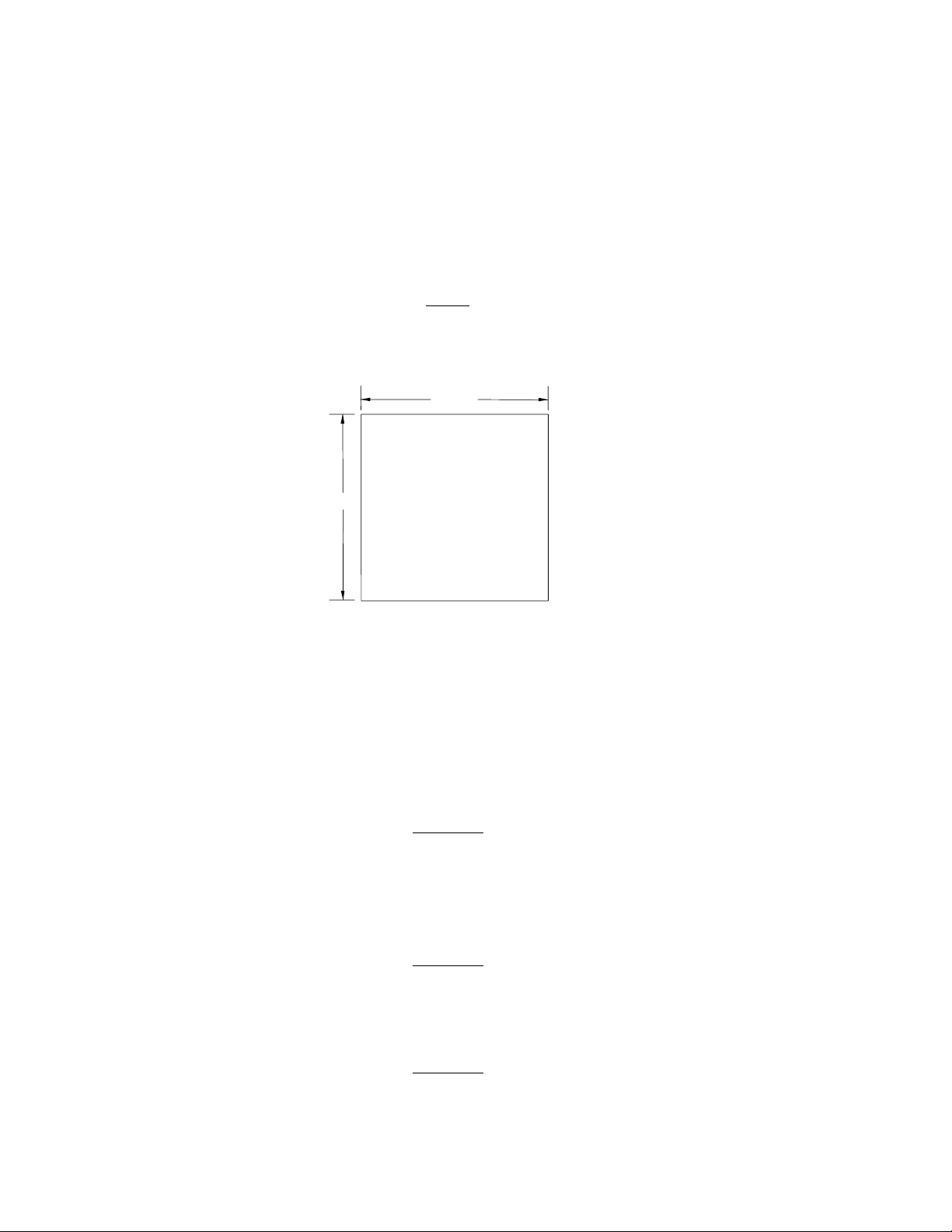
B. Verify that the unit will fit in the desired location. See Figure 1 for the counter cutout for the unit.
NOTE
Remember that the unit can extend up to 23 inches (58.42 cm) below the counter, including the
shipping risers, which Lancer recommends be left attached to the unit. Should the dispenser
ever require removal, the shipping risers will protect the inlet tubes from being damaged.
C. After the counter cutout is complete, the unit may be lowered into the counter.
1.8 CONNECTION OF THE UNIT
A. Position the CO2 gas tank in location. Assemble high pressure regulator to CO2 gas tank and
run jumper line to low pressure regulator.
B. Attach the CO
2 gas line to the carbonator by attaching the line from the high pressure regulator
to the single check valve marked "gas" on top of the carbonator tank. The setting of the high
pressure CO2 gas regulator should be 90 PSI to 110 PSI.
CAUTION
DO NOT TURN ON THE CO2 AT THIS TIME.
C. Position the syrup tanks in the desired location. Attach the CO2 gas lines leading from the low
pressure regulator to these tanks.
D. Connect syrup lines from tanks to the appropriate inlets at the right front of the unit. The syrup
inlets are identified.
CAUTION
A FILTER IN THE WATER LINE MUST BE USED IF THE WATER SUPPLY CONTAINS ANY
APPRECIABLE AMOUNT OF SILT, SAND, OR ANY OTHER DEBRIS. FAILURE TO DO SO CAN
RESULT IN EQUIPMENT DAMAGE.
E. Mount the water filter assembly (if used) and water regulator in a convenient location.
CAUTION
FAILURE TO LIMIT WATER PRESSURE TO 50 PSI WILL RESULT IN IMPROPER
PERFORMANCE OF THE DISPENSER.
F. Connect water inlet line to water regulator, to water filter, and then to the water inlet of the
Counter Cutout for dispenser
Figure 1
23 1/4"
23 1/4"
Page 5
carbonator pump on the carbonator.
G. Provide a suitable drain in the plumbing system and attach the one (1) inch (2.54 cm) diameter
schedule 40 PVC drains to it. The drip pan drainage outlet is located at the center rear of the
unit. The ice water drainage outlet is located at the right front of the unit.
H. Be sure to place the ice trap in the drain outlet inside the ice bin before filling the cabinet with
ice. This device holds the ice away from the drain outlet, allowing the ice water to drain
properly.
W
ARNING
THE POWER SUPPLY MUST BE PROPERLY ELECTRICALLY GROUNDED TO AVOID
POSSIBLE ELECTRICAL SHOCK OR SERIOUS INJURY TO THE OPERATOR. THE POWER
CORD IS PROVIDED WITH A THREE PRONG GROUNDED PLUG. IF A THREE-HOLE
GROUNDED ELECTRICAL OUTLET IS NOT AVAILABLE, USE AN APPROVED METHOD TO
GROUND THE UNIT.
I. Plug in the transformer box to a standard 15 AMP, 110 VAC, single phase outlet. The unit will
internally convert the 110 VAC to 24 VAC.
1.9 START UP
A. After all connections to water, CO
2 gas, electrical power, and syrup containers are made, check
for leaks.
B. Be sure syrup tanks contain syrup.
CAUTION
DO NOT OPERATE CARBONATOR PUMP WITH WATER SUPPLY SHUT OFF.
C. Turn on water; open the pressure relief valve on the carbonator tank by lifting the wire ring or
flipping lever, and hold it open until water flows from the relief valve. Close the relief valve and
turn on the CO
2 gas and electrical power in that order.
D. To fill all lines with water, cycle the carbonator several times by operating the dispensing valves.
1. A low pressure gas regulator controls the flow of syrup to each dispensing valve. For
proper operation of the valves, the pressure regulator should be set so that 40 PSI is at the
backblock of the valve.
2. For diet type syrup, the tank pressures should be set at 10 PSI (or as recommended by the
3
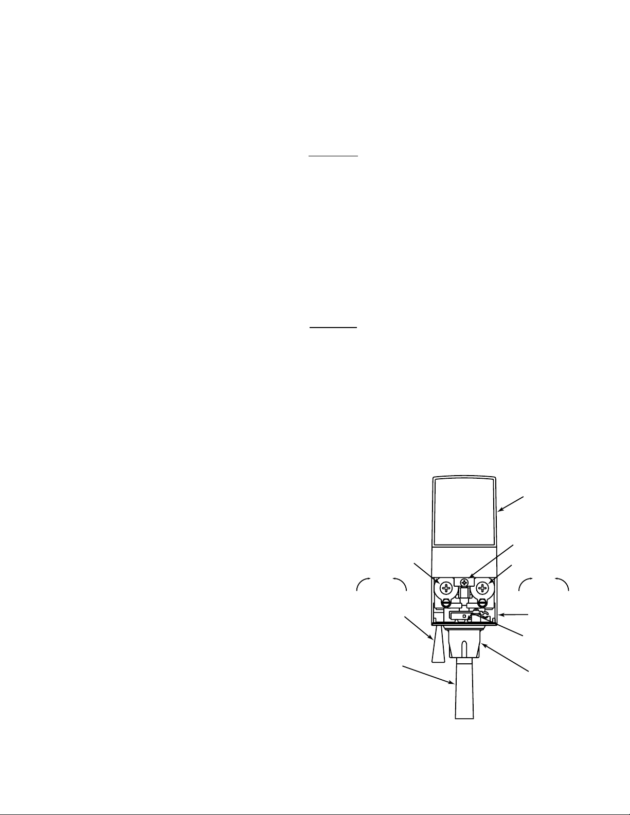
Valve Adjustments
Figure 2
syrup supplier). Additional pressure
may be necessary, depending on the
distance from the syrup tank to the
unit.
E. The unit should now be filled with ice
cubes to the level of the door opening.
1.10 ADJUSTING WATER FLOW
A. The water flow can be adjusted to either
1.25 ounces/second (37 ml/sec) or 2.50
ounces/second (74 ml/sec) on all
dispensing valves, using the following
procedure.
B. The unit should have ice on cold plate for
a least one hour before you attempt to
brix the valves. The drink temperature
should be no higher than 40
o
F (4.4oC)
when the ratio is set. This is done after
the unit has ice in the ice bin.
C. Slide the ID panel UP, until the flow
controls are exposed (see Figure 2).
D. Remove nozzle by twisting counter
clockwise and pulling down.
E. Remove diffuser by pulling down.
I.D. PANEL
open position)
FLOW CONTROL
SYRUP
DecreaseIncrease
SODA LEVER
(Optional)
CUP LEVER
COVER SCREW
FLOW CONTROL
MANUFACTURE
SERIES NO.
(Shown in
SYRUP
DecreaseIncrease
COVER
DATE OF
NOZZLE
Page 6

F. Install Lancer (yellow) syrup separator (PN 54-0031) in place of nozzle.
G. Activate dispensing valve to fill separator syrup tube.
H. Hold a Lancer brix cup under the syrup separator and dispense water and syrup into cup for
four (4) seconds. Divide number of ounces (ml) of water in cup by four (4) to determine water
flow rate per second.
I. To obtain the proper flow, use a screwdriver to adjust water flow control (see Figure 2).
J. Repeat process for each valve.
1.11 ADJUSTING WATER TO SYRUP RATIO (BRIX)
A. Hold the Lancer brix cup under the syrup separator and activate valve. Check ratio (brix).
B. To obtain the proper ratio, use screwdriver to adjust syrup flow control (see Figure 2).
C. Remove syrup separator.
D. Install diffuser and nozzle.
E. Slide ID panel DOWN.
F. Repeat process for each valve.
NOTE
In all cases of reassembly of valves involving o-rings, be sure the o-ring is lubricated with an
FDA approved lubricant or water to prevent leakage or damage to the o-ring.
1.12 REPLENISHING SYRUP SUPPLY (5 GALLON TANKS)
A. To add syrup to a tank after the system is in operation, the following procedure should be used.
1. Shut off CO
2 gas supply system to syrup tanks.
2. Snap off the self-sealing quick-coupler and allow gas in syrup tank to escape by pulling the
outer shell of the quick-coupler toward the flexible line and allowing the whole connection to
pull free.
W
ARNING
TO AVOID POSSIBLE PERSONAL INJURY OR PROPERTY DAMAGE, DO NOT ATTEMPT
TO REMOVE SYRUP TANK COVER UNTIL CO
2 PRESSURE HAS BEEN RELEASED FROM
TANK.
3. Remove the cover by pulling upward on the hinged locking bar.
4. Fill tank with appropriate syrup, leaving one (1) inch (2.54 cm) of space for CO2 gas.
5. Replace locking cover insuring that the cover and cover gasket are properly aligned.
6. Snap on quick-coupler and lock it securely in place. Turn CO
2
gas pressure ON. When
properly connected, the gas will automatically enter the tank with an audible noise.
2. RECOMMENDED SERVICE AND MAINTENANCE
2.1 SCHEDULED
A. Daily – See Section 2.5 for daily cleaning.
B Monthly – See Section 2.6 for monthly cleaning.
C. Periodic Sanitizing - See sections 2.2, 2.3, and 2.4 for sanitizing requirements.
D. As Needed - Keep exterior surfaces (to include drip tray and cup rest) of dispenser cleaned with
damp, clean cloth.
2.2 CLEANING AND SANITIZING SYSTEMS
A. General Information
(1) Lancer equipment (new or reconditioned) is shipped from the factory cleaned and sanitized
in accordance with NSF guidelines. The operator of the equipment must provide
continuous maintenance as required by this manual and/or state and local health
department guidelines to ensure proper operation and sanitation requirements are
maintained.
NOTE
The cleaning and sanitizing procedures provided herein pertain to the Lancer equipment
identified by this manual. If other equipment is being cleaned, follow the guidelines
established for that equipment.
4
Page 7

(2) Cleaning and sanitizing should be accomplished only by trained personnel. Sanitary gloves
are to be used during cleaning and sanitizing operations. Applicable safety precautions
must be observed. Instruction warnings on the product being used must be followed.
IMPORT
ANT
Water lines are not to be disconnected during the cleaning and sanitizing of syrup lines to
avoid contamination.
(3) Recommended Preparation of Cleaning Solutions.
(a) Cleaning solutions (for example, Ivory Liquid, Calgon, etc.) mixed with clean, potable
water at a temperature of 90 to 110 degrees Fahrenheit should be used to clean
equipment. The mixture ratio, using Ivory Liquid, is one (1) ounce of cleanser to two (2)
gallons of water. A minimum of four (4) gallons of cleaning mixture should be prepared.
NOTE
Extended lengths of product lines may require that an additional volume of solution be
prepared.
(b) Any equivalent cleanser may be used as long as it provides a caustic based,
non-perfumed, easily rinsed mixture containing at least two (2) percent sodium
hydroxide (NaOH).
(4) Recommended Preparation of Sanitizing Solutions.
(a) Sanitizing solutions should be prepared in accordance with the manufacturer’s written
recommendations and safety guidelines. Follow manufacturer’s requirements so that
the solution provides 200 parts per million (PPM) available chlorine at a temperature of
90
o
F to 120oF. A minimum of four (4) gallons of sanitizing solution should be prepared.
NOTE
Extended lengths of product lines may require that an additional volume of solution be
prepared.
(b) Any sanitizing solution may be used as long as it is prepared in accordance with the
manufacturer’s written recommendations and safety guidelines, and provides 200 parts
per million (PPM) available chlorine.
2.3 CLEANING AND SANITIZING FIGAL SYSTEMS
A. Remove all ice from ice bin by melting with hot water.
B. Remove quick disconnect from syrup tank.
CAUTION
DO NOT USE A WIRE BRUSH TO CLEAN VALVES.
C. Using a clean plastic bristle brush and a detergent soap solution prepared in accordance with
the instructions in Section 2.2, scrub both valves of the disconnect. Rinse with clean, potable
water.
D. Using a mechanical spray bottle and a sanitizing solution prepared in accordance with the
instructions in Section 2.2, spray both halves of the quick disconnects. Allow to air dry.
NOTE
Please note that a fresh water rinse cannot follow sanitization of equipment. Purge only with the
end use product. This is an NSF requirement.
E. Connect syrup line to a syrup tank filled with clean, potable, room temperature water. Connect
CO
2 supply hose to tank and pressurize.
F. Place waste container under applicable dispensing valve. Activate valve until water is
dispensed. Flush and rinse line and fittings for a minimum of 60 seconds to remove all traces
of residual product.
NOTE
Extended lengths of product lines may require additional time for flushing and rinsing lines.
5
Page 8

WARNING
TO AVOID POSSIBLE PERSONAL INJURY OR PROPERTY DAMAGE, DO NOT ATTEMPT
TO REMOVE SYRUP TANK COVER UNTIL CO2PRESSURE HAS BEEN RELEASED FROM
TANK.
G. Disconnect CO
2 supply hose from the water filled syrup tank.
H. Prepare cleaning solution as described in Section 2.2 above. Fill a tank with cleaning solution.
Connect syrup line to the tank. Connect CO
2 supply hose to tank and pressurize.
I. Place waste container under applicable dispensing valve. Activate valve and draw cleaning
solution through lines for a minimum of 60 seconds. This will ensure line is flushed and filled
with cleaning solution. Allow line to stand for at least 30 minutes.
NOTE
Extended lengths of product lines may require additional time for flushing and filling lines.
J. Disconnect CO2supply hose from the tank.
K. Connect syrup line to a tank filled with clean, potable, water at a temperature of 90 to 110
o
F.
Connect CO
2 supply hose to tank and pressurize.
L. Place waste container under applicable dispensing valve. Activate valve to flush and rinse line
and fittings for a minimum of 60 seconds to remove all traces of cleaning solution. Continue
rinsing until testing with phenolpthalein shows that the rinse water is free of residual detergent.
M. Disconnect CO
2 supply hose from the tank.
N. Fill a tank with sanitizing solution. Connect syrup line to the tank. Connect CO2 supply hose to
tank and pressurize.
O. Remove dispensing valve nozzle (twist and pull down) and pull out center mixing baffle. Using
a plastic bristle brush and detergent soap solution scrub the nozzle, mixing baffle, bottom of
dispensing valve, and cup lever. Rinse with clean water.
P. Reassemble mixing baffle and nozzle.
Q. Place waste container under applicable dispensing valve. Activate valve and draw sanitizing
solution through line for a minimum of 60 seconds. This will ensure line is flushed and filled with
sanitizing solution. Allow line to stand for at least 30 minutes.
R. Disconnect CO
2 supply hose from the tank.
S. Reconnect syrup lines to syrup containers (for example, quick disconnects, figal containers, etc.)
and ready unit for operation.
W
ARNING
FLUSH SANITIZING SOLUTION FROM SYRUP SYSTEMS AS INSTRUCTED. RESIDUAL
SANITIZING SOLUTION LEFT IN SYSTEM COULD CREATE A HEALTH HAZARD.
T. Draw drinks and refill lines with end product to flush sanitizing solution from the dispenser.
NOTE
Please note that a fresh water rinse cannot follow sanitization of equipment. Purge only with the
end use product. This is an NSF requirement.
U. Test dispenser in normal manner for proper operation. Taste dispensed product to ensure there
is no off-taste. If off-taste is found, additional flushing of syrup system may be required.
V. Repeat cleaning, rinsing, and sanitizing procedures for each valve/syrup circuit.
W. Clean exterior of unit as instructed in Section 2.6.
X. Using a spray bottle of sanitizing solution, spray the underside of all dispenser valves, valve
spouts and cup levers. Allow to air dry.
NOTE
Thoroughly rinse inside and outside of syrup tank that was used for sanitizing solution with plain
water to remove all solution residue.
Y. Fill ice bin with ice. Install ice bin cover on unit.
2.4 CLEANING AND SANITIZING BAG-IN-BOX (BIB) SYSTEMS
A. Disconnect syrup quick disconnect coupling from syrup packages and connect coupling to a bag
6
Page 9

valve removed from an empty Bag-in-Box package.
B. Place end of syrup inlet line, with bag valve attached, in a clean container filled with clean,
potable, room temperature water.
C. Place waste container under applicable dispensing valve. Activate valve until water is
dispensed. Flush and rinse line and fittings for a minimum of 60 seconds to remove all traces
of residual product.
NOTE
Extended lengths of product lines may require additional time for flushing and rinsing lines.
D. Prepare cleaning solution as described in Section 2.2 above. Place end of syrup inlet line in
container filled with cleaning solution.
E. Place waste container under applicable dispensing valve. Activate valve and draw cleaning
solution through lines for a minimum of 60 seconds. This will ensure line is flushed and filled
with cleaning solution. Allow line to stand for at least 30 minutes.
F. Place end of syrup inlet line in a clean container filled with clean, potable, water at a
temperature of 90 to 110
o
F.
G. Place waste container under applicable dispensing valve. Activate valve to flush and rinse line
and fittings for a minimum of 60 seconds to remove all traces of cleaning solution. Continue
rinsing until testing with phenolpthalein shows that the rinse water is free of residual detergent.
H. Prepare sanitizing solution as described in Section 2.2 above. Place end of syrup inlet line in
container filled with sanitizing solution which has been prepared.
I. Activate valve and draw sanitizing solution through line for a minimum of 60 seconds. This will
ensure line is flushed and filled with sanitizing solution. Allow line to stand for at least
30 minutes.
J. Remove bag valve from quick disconnect coupling and reconnect syrup inlet line to syrup
package. Ready unit for operation.
W
ARNING
FLUSH SANITIZING SOLUTION FROM SYRUP SYSTEMS AS INSTRUCTED. RESIDUAL
SANITIZING SOLUTION LEFT IN SYSTEM COULD CREATE A HEALTH HAZARD.
K. Draw drinks and refill lines with end product to flush sanitizing solution from the dispenser.
NOTE
Please note that a fresh water rinse cannot follow sanitization of equipment. Purge only with the
end use product. This is an NSF requirement.
L. Test dispenser in normal manner for proper operation. Taste dispensed product to ensure there
is no off-taste. If off-taste is found, additional flushing of syrup system may be required.
M. Repeat cleaning, rinsing, and sanitizing procedures for each valve circuit.
2.5 VALVES
A. Valves may be cleaned and sanitized (see preparation in Section 2.2) in the same manner.
1. Remove cover and disconnect power so the valve will not be activated during the cleaning
procedure. Remove nozzle and diffuser. Wash these parts in cleaning solution; then
immerse them in a bath of sanitizing solution for 15 minutes.
2. Visually inspect around nozzle area for syrup residue. This area may be cleaned with warm
water and cloth or with the nozzle brush supplied. Wipe off dispensing lever.
3. Wearing sanitary gloves, remove, drain and air dry the nozzle and diffuser.
4. Wearing sanitary gloves, replace diffuser, twist nozzle in place.
5 Connect power and replace cover. Valve is ready for operation.
2.6 ICE BIN COMPARTMENT ON ALL ICE CHESTS
A. The ice bin compartment of the dispenser should be thoroughly cleaned and sanitized at least
once every month. Use. the following procedure.
B. Prepare cleaning solution and sanitizing solution in accordance with Section 2.2.
C. Using the cleaning solution and a clean soft cloth, wash down the sides of the ice bin and the
surface of the aluminum casting.
7
Page 10

D. Using clean, potable water, thoroughly rinse away the cleaning solution from the sides and
surface of the casting.
E. Using plastic sanitary gloves, soak a white cotton gauze cleaning rag in the sanitizing solution
and wipe all surfaces in the ice compartment.
NOTE
Please note that a fresh water rinse cannot follow sanitization of equipment. Purge only with the
end use product. This is an NSF requirement.
F. Sanitizing of the ice compartment is complete. Refill with ice.
3. TROUBLESHOOTING
TROUBLE
CAUSE
REMEDY
CAUTION
POURING HOT WATER INTO DRAIN MAY CAUSE THE DRAIN TUBE TO COLLAPSE. ALLOW ONLY
LUKEWARM OR COLD WATER TO ENTER DRAIN TUBE.
POURING COFFEE, TEA, AND LIKE SUBSTANCES INTO DRAIN MAY CAUSE THE DRAIN TUBE TO
BECOME CLOGGED WITH COFFEE OR TEA GROUNDS, OR OTHER SOLID PARTICLES.
3.1 No carbonation. A. Carbonator motor not running. A. Check power supply. Be sure
toggle switch is in ON position.
B. Absence of CO2 gas. B. Replace with full tank of CO2 gas.
C. Gas only from valves. C. Check for power failure. Check
fuses. Clean strainer on pump.
D. Carbonator tank air bound. D. Relieve gas pressure in tank by
pulling ring on safety relief valve
until water spurts out.
E. CO2 gas pressure below E. Reset high pressure CO
2
gas
90 PSI. regulator to 90-110 PSI. Change
CO
2 tank if required.
F. Carbonator motor running F. Check switch on carbonator.
continuously. Check water in check valve for
blockage. Check carbonator
control. Check carbonator pump for
efficiency.
3.2 Noisy Carbonator A. Insufficient water supply or A. Provide adequate water supply.
Pump. water leak, allowing air to Check strainer for Cleanliness.
be pulled into pump.
B. Loose pump coupling. B. Tighten set screw on pump
coupling.
3.3 Off taste in soda. A. Leaking water check valve, A. Dismantle and clean check valve.
allowing carbonated water Replace O-Ring, if torn or distorted.
to back into supply line.
3.4 Valves inoperable. A. Loss of power. A. Check power supply to see if
plugged in. Check transformer
circuit breaker. Check main power
circuit breaker, 110V.
8
Page 11

9
NOTES
Page 12

4. ILLUSTRATIONS, PARTS LISTINGS, AND WIRING DIAGRAMS
4.1 SERIES 2300 DROP-IN
10
13
8
12
14
7
15
16
11
10
9
6
26
25
5
24
29 28
27
4
COVER MUST BE COMPLETELY
CLOSED TO OPERATE VALVES
SLIDING COVER
3
DO NOT LIFT
17
18
19
20
21
22
23
1
35
30
2
31
32
33
34
Page 13

11
4.1 SERIES 2300 DROP-IN (CONTINUED)
ITEM PART NO. DESCRIPTION
1 42-0035 Tank Assy, High Performance
- 42-0036 Tank Assy, Standard Performance
2 30-5473/03 Tank Wrapper
3 51-1236/01 Rim Assy
4 30-7140 Lid, Ice Bin
5 19-0077 LEV
®
- 19-0078 LEV® with Soda Lever
6 05-1074/01 Drip Tray
7 23-0797/02 Cup Rest
8 30-5424 Splash Plate
9 04-0459 Screw, 10 - 32 X 1.000 (for LEV
®
only)
10 30-6052 Door Stop
11 04-1028 Screw, 10 - 32 X 0.375
12 51-5089/01 Faucet Plate (5 Valve Stainless Steel)
- 51-5088/01 Faucet Plate (6 Valve Stainless Steel)
13 52-0828/03 Wire Harness Assy. (5 Valve)
- 52-0827/03 Wire Harness Assy. (6 Valve)
14 48-0776 Foamed Manifold (5 Valve, 4-1)
- 48-0767 Foamed Manifold (6 Valve, 5-1)
- 48-0851 Foamed Manifold (5 Valve, 2-1-2)
- 48-0850 Foamed Manifold (6 Valve, 3-1-2)
15 07-0360 Plug
16 30-5986 Tower Cap
17 04-0148 Screw, 10 - 32 X 0.250
18 07-0555 Plug
19 12-0097 Key Lock Switch Assy
20 81-0126 Key
21 51-5161/01 Tower Body (Stainless Steel)
22 06-0645-05 Nameplate (5 Valve)
- 06-0645-06 Nameplate (6 Valve)
23 51-5541 Base Assy.
24 82-1490 Switch Bracket Assy
25 30-7004 Wire Clip
26 82-1094 Casual Drink Device
27 07-0556 Plug
28 13-0015 Bushing
29 11-0015 Housing Socket
30 04-0072 Rivet
31 23-0862 Wire Drain Assy
32 30-0294 Shipping Riser
33 04-0510 Screw, 8 - 18 X 0.500
34 30-5151 Shipping Riser, Large
35 82-1103 Transformer Assy
Page 14

12
4.2 SERIES 2400 FREE-STANDING
8
11
13
12
7
14
15
6
10
9
16
17
29
18
26
5
4
28
27
25
23
24
19
20
21
3
COVER MUST BE COMPLETELY
CLOSED TO OPERATE VALVES
SLIDING COVER
DO NOT LIFT
22
1
30
31
2
32
33
34
36
35
Page 15

ITEM PART NO. DESCRIPTION
1 42-0035 Tank Assy, High Performance
- 42-0036 Tank Assy, Standard Performance
2 51-0641/02 Tank Wrapper
3 51-5227/02 Rim Assy
4 30-7140 Lid, Ice Bin
5 19-0077 LEV
®
- 19-0078 LEV® with Soda Lever
6 05-1074/01 Drip Tray
7 23-0797/02 Cup Rest
8 30-5424 Splash Plate
9 30-6052 Door Stop
10 04-1028 Screw, 10 - 32 X 0.375
11 51-5089/01 Faucet Plate (5 Valve Stainless Steel)
- 51-5088/01 Faucet Plate (6 Valve Stainless Steel)
12 52-0828/03 Wire Harness Assy. (5 Valve)
- 52-0827/03 Wire Harness Assy. (6 Valve)
13 48-0776 Foamed Manifold (5 Valve, 4-1)
- 48-0767 Foamed Manifold (6 Valve, 5-1)
- 48-0851 Foamed Manifold (5 Valve, 2-1-2)
- 48-0850 Foamed Manifold (6 Valve, 3-1-2)
14 07-0360 Plug
15 30-5986 Tower Cap
16 04-0148 Screw, 10 -32 X 0.250
17 07-0555 Plug
18 12-0097 Key Lock Switch Assy
19 81-0126 Key
20 51-5161/01 Tower Body (Stainless Steel)
21 06-0645-05 Nameplate (5 Valve)
- 06-0645-06 Nameplate (6 Valve)
22 51-5541 Base Assy
23 82-1490 Switch Bracket Assy
24 30-7004 Wire Clip
25 82-1094 Casual Drink Device
26 07-0556 Plug
27 13-0015 Bushing
28 11-0015 Housing Socket
29 04-0459 Screw, 10 - 32 X 1.000 (for
LEV
® only)
30 30-6200 Back Access Door
31 04-0072 Rivet
32 23-0862 Wire Drain Assy
33 04-0608 Screw, 10 - 32 X 1.500
34 81-0011 Legs
35 30-0797/01 Front Access Door
36 82-1103 Transformer Assy
13
4.2 SERIES 2400 FREE-STANDING
Page 16

4.3 SERIES 2300 DROP-IN WITH PLUG IN TOWERS
14
10
11
13
12
9
14
15
16
27
28
8
17
18
24
23
7
25
26
19
20
6
5
4
COVER MUST BE COMPLETELY
CLOSED TO OPERATE VALVES
SLIDING COVER
DO NOT LIFT
21
22
3
35
29
1
30
31
2
32
33
34
Page 17

ITEM PART NO. DESCRIPTION
1 42-0048 Tank Assy
2 30-5473/03 Tank Wrapper
3 51-1236/01 Rim Assy
4 30-7140 Lid, Ice Bin
5 13-0005 Bushing
6 11-0015 Housing Socket
7 19-0077 LEV
®
- 19-0078 LEV® with Soda Lever
8 05-1147 Drip Tray
9 23-0797/02 Cup Rest
10 30-5424 Splash Plate
11 04-0558 Screw, 10 - 32 X 0.375
12 51-5089/01 Faucet Plate (5 Valve Sabre)
- 51-0711/01 Faucet Plate (6 Valve Sabre)
- 51-5089/01 Faucet Plate (5 Valve Stainless Steel)
- 51-5088/01 Faucet Plate (6 Valve Stainless Steel)
13 52-0828/03 Wire Harness Assy (5 Valve)
- 52-0827/03 Wire Harness Assy (6 Valve)
14 51-5161/01 Tower Body (Stainless Steel)
- 51-5019/01 Tower Body (Sabre)
15 06-0234 Coca-Cola, Sabre, Sign
16 05-0332 Mounting Graphic Panel
17 48-1134 Foamed Manifold (5 Valve Sabre
Plug In)
- 48-0744 Foamed Manifold (6 Valve Sabre
Plug In)
- 48-1133 Foamed Manifold (5 Valve Stainless
Steel Plug In)
- 48-0951 Foamed Manifold (6 Valve Stainless
Steel Plug In)
18 05-1516 Plug, Sabre, Gray
19 12-0097 Key Lock Switch Assy
20 81-0126 Key
21 06-0645-55 Nameplate (5 Valve Sabre)
- 06-0645-56 Nameplate (6 Valve Sabre)
- 06-0645-05 Nameplate (5 Valve Stainless Steel)
- 06-0645-06 Nameplate (6 Valve Stainless Steel)
22 51-5541 Base Assy
23 82-1490 Switch Bracket Assy
24 30-7004 Wire Clip
25 07-0556 Plug
26 04-0459 Screw
27 04-1028 Screw, 10 - 32 X 0.375
28 30-6184/01 Bracket, Tower Stiffener
29 02-0003 O-ring
30 04-0072 Rivet
31 23-0862 Wire Drain Assy
32 30-0294 Shipping Riser
33 04-0510 Screw, 8 - 18 X 0.500
34 30-5151 Shipping Riser, Large
35 82-1103 Transformer Assy
4.3 SERIES 2300 DROP-IN WITH PLUG IN TOWERS (CONTINUED)
15
Page 18

4.4 SERIES 2400 FREE-STANDING WITH PLUG IN TOWERS
16
14
13
12
11
10
9
27
28
15
16
17
8
24
23
7
6
5
4
3
1
2
26
25
21
18
19
20
22
29
30
31
32
33
36
34
35
Page 19

ITEM PART NO. DESCRIPTION
1 42-0048 Tank Assy
2 51-0641/02 Tank Wrapper
3 51-5227/02 Rim Assy
4 30-7140 Lid, Ice Bin
5 13-0005 Bushing
6 11-0015 Housing Socket
7 19-0077 LEV
®
- 19-0078 LEV® with Soda Lever
8 05-1147 Drip Tray
9 23-0797/02 Cup Rest
10 30-5424 Splash Plate
11 04-0558 Screw, 10 - 32 X 0.375
12 51-5089/01 Faucet Plate (5 Valve Sabre)
- 51-0711/01 Faucet Plate (6 Valve Sabre)
- 51-5089/01 Faucet Plate (5 Valve Stainless Steel)
- 51-5088/01 Faucet Plate (6 Valve Stainless Steel)
13 52-0828/03 Wire Harness Assy (5 Valve)
- 52-0827/03 Wire Harness Assy (6 Valve)
14 51-5161/01 Tower Body (Stainless Steel)
- 51-5019/01 Tower Body (Sabre)
15 06-0234 Coca-Cola Sabre Sign
16 05-0332 Mounting Graphic Panel
17 48-1134 Foamed Manifold (5 Valve Sabre
Plug In)
- 48-0744 Foamed Manifold (6 Valve Sabre
Plug In)
- 48-1133 Foamed Manifold (5 Valve Stainless
Steel Plug In)
- 48-0951 Foamed Manifold (6 Valve Stainless
Steel Plug In)
18 05-1516 Plug Sabre Gray
19 12-0097 Key Lock Switch Assy
20 81-0126 Key
21 06-0645-55 Nameplate (5 Valve Sabre)
- 06-0645-56 Nameplate (6 Valve Sabre)
- 06-0645-05 Nameplate (5 Valve Stainless Steel)
- 06-0645-06 Nameplate (6 Valve Stainless Steel)
22 51-5541 Base Assy
23 82-1490 Switch Bracket Assy
24 30-7004 Wire Clip
25 07-0556 Plug
26 04-0459 Screw, 10 - 32 X 1.000 (for
LEV
® only)
27 04-1028 Screw, 10 - 32 X 0.375
28 30-6184 Bracket, Tower Stiffener
29 02-0003 O-ring
30 30-6200 Back Access Door
31 04 0072 Rivet
32 23-0862 Wire Drain Assy
33 04-0608 Screw, 10 - 32 X 1.500
34 81-0011 Legs
35 30-0797/01 Front Access Door
36 82-1103 Transformer Assy
4.4 SERIES 2400 FREE-STANDING WITH PLUG IN TOWERS (CONTINUED)
17
Page 20

18
4.5 SERIES 2300 DROP-IN (PRE-MIX)
8
10
11
7
9
6
5
4
3
1
12
13
14
15
16
17
18
19
20
21
22
23
24
2
28
25
26
27
Page 21

ITEM PART NO. DESCRIPTION
1 42-0038 Tank Assy
2 30-5473/03 Tank Wrapper
3 51-1236/01 Rim Assy
4 30-7140 Lid, Ice Bin
5 19-0002 Pre-Mix Valve
6 05-1074/01 Drip Tray
7 23-0797/02 Cup Rest
8 30-5424 Splash Plate
9 04-1028 Screw 10 - 32 X 0.375
10 30-5731 Faucet Plate (5 Valve)
- 30-5730 Faucet Plate (6 Valve)
11 51-5161/01 Tower Body (Stainless Steel)
12 07-0360 Plug
13 30-5986 Tower Cap
14 04-0148 Screw, 10- 32 X 0.250
15 07-0555 Plug
16 C-15-0794-100 Yoke Fitting
17 01-0222 Fitting
18 07-0405 Plug
19 07-0438 Clamp, Oetiker
20 08-0263 Tubing, Red Line
21 88-0118 Insulation
22 06-0645-05 Nameplate (5 Valve)
- 06-0645-06 Nameplate (6 Valve)
23 51-5541 Base Assy
24 04-0072 Rivet
25 23-0862 Wire Drain Assy
26 30-0294 Shipping Riser
27 04-0510 Screw, 8 - 18 X 0.500
28 30-5151 Shipping Riser, Large
19
4.5 SERIES 2300 DROP-IN (PRE-MIX) (CONTINUED)
Page 22

4.6 SERIES 2400 FREE-STANDING (PRE-MIX)
20
11
8
10
7
9
6
5
4
3
1
2
12
13
14
15
16
17
18
19
20
21
22
23
24
25
26
29
27
28
Page 23

ITEM
PART NO. DESCRIPTION
1 42-0038 Tank Assy
2 51-0641/02 Tank Wrapper
3 51-5227/02 Rim Assy
4 30-7140 Lid, Ice Bin
5 19-0002 Premix Valve
6 05-1074/01 Drip Tray
7 23-0797/02 Cup Rest
8 30-5424 Splash Plate
9 04-1028 Screw, 10 - 32 X 0.375
10 30-5731 Faucet Plate (5 Valve)
- 30-5730 Faucet Plate (6 Valve)
11 51-5161/01 Tower Body (Stainless Steel)
12 07-0360 Plug
13 30-5986 Tower Cap
14 04-0148 Screw, 10 - 32 X 0.250
15 07-0555 Plug
16 C-15-0794-100 Yoke Fitting
17 01-0222 Fitting
18 07-0405 Plug
19 07-0438 Clamp, Oetiker
20 08-0263 Red Line, Tubing
21 88-0118 Insulation
22 06-0644-05 Nameplate (5 Valve)
- 06-0644-06 Nameplate (6 Valve)
23 51-5541 Base Assy
24 30-6200 Back Access Door
25 04-0072 Rivet
26 23-0862 Wire Drain Assy
27 04-0608 Screw 10 - 32 X 1.500
28 81-0011 Legs
29 30-0797/01 Front Access Door
4.6 SERIES 2400 FREE-STANDING (PRE-MIX) (CONTINUED)
21
Page 24

22
4.7 ICE COOLED UNIVERSAL WIRING DIAGRAM WITH BIN LID SWITCH
BLACK
WHITE
PRESSURE SWITCH
3F
LIGHT KIT
3M
SYRUP OUT
CDA
SOLENOID
BLACK
PCB
1
BLACK
2F
WHITE
BLACK
2M
WHITE
2
62F543
F
WHITE
2F
2M
BLACK
WHITE
Y
WHITE
KEY
F
BLACK
WHITE
M
LOCK
FY
F
BLACK
WHITE
F
F
SOLENOID
WATER SPIGOT
2F
2M
2F
2M
BLACK
F
ORIGINAL
POWER SUPPLY
2F
2M
F
F
F
F
BUTTON
WATER SPIGOT
2F
2F
2F
2M
2F
ON SPRITE VALVE
REPLACES INTERNAL
CHERRY SWITCH HARNESS
F M
VALVE MANIFOLD HARNESS
F
WHITE
F
F
BIN
SWITCH
M
WHITE
F
Y
ALTERNATE
POWER SUPPLY
2F
IN CONJUNCTION WITH
THIS HARNESS IS NOT USED
ALTERNATE POWER SUPPLY
2F
2M
OR
MARQUEE
MERCHANDISER
: 2 PIN FEMALE CONNECTOR
: MALE BLADE
: FEMALE BLADE RECEPTACLE
F
M
2F
: "Y" CONNECTOR (2 MALES, 1 FEMALE)
: 2 PIN MALE CONNECTOR
: 3 PIN MALE CONNECTOR
: 3 PIN FEMALE CONNECTOR
Y
3F
2M
3M
Page 25

23
4.8 ICE COOLED UNIVERSAL WIRING DIAGRAM WITHOUT BIN LID SWITCH
BLACK
WHITE
3F
3M
LIGHT KIT
SYRUP OUT
CDA
SOLENOID
2F
2M
BLACK
WHITE
PCB
2
1
PRESSURE SWITCH
BLACK
543 6
BLACK
WHITE
2M
BLACK
WHITE
WATER SPIGOT
KEY
LOCK
F
Y
F
F
WHITE
WHITE
BLACK
2F
WHITE
Y
F
BLACK
2M
WHITE
2F
F
M
F
F
SOLENOID
2F
2M
BLACK
ORIGINAL
POWER SUPPLY
2F
2M
F
F
F
F
BUTTON
WATER SPIGOT
2M
2F 2F 2F 2F 2F
ON SPRITE VALVE
REPLACES INTERNAL
CHERRY SWITCH HARNESS
MF
VALVE MANIFOLD HARNESS
F
Y
ALTERNATE
POWER SUPPLY
2F
IN CONJUNCTION WITH
THIS HARNESS IS NOT USED
ALTERNATE POWER SUPPLY
2F
2M
OR
MARQUEE
MERCHANDISER
: 2 PIN FEMALE CONNECTOR
: FEMALE BLADE RECEPTACLE
: MALE BLADE
F
M
2F
: "Y" CONNECTOR (2 MALES, 1 FEMALE)
: 2 PIN MALE CONNECTOR
: 3 PIN MALE CONNECTOR
: 3 PIN FEMALE CONNECTOR
Y
3F
3M
2M
Page 26

4.9 LANCER ICE COOLED DISPENSER -- ACCESSORIES
24
Illuminated Merchandiser
PN 85-2304
Illuminated Marquee
PN 85-2302
T & S Valve for Chilled Water
PN 19-0036
Water Spigot for Ambient
Temperature Water Kit
PN 82-1597
Splash Guards Kit
PN 82-2076
Page 27

Directory of USA - Canada Offices,
International Offices, and Authorized Distributors (Continued)
(Continued from previous page)
EcuaLancer S.A. - Ecuador
Lancer Sales Company
Contact: Luciano Lopez
Sector Las Acacias
Luis De Beethoven #958
Y Capitan Rafael Ramos
Quito, Ecuador
Phone: 593-22-401-598, 400-937, 406-418
FAX: 593-22-400-535
e-mail: Llopez@ecnet.ec
Lancer Authorized Distributors
Eximport & Barter Co. - Caribbean
2101 S.W. 56th Terrace
Hollywood, FL 33023 USA
Phone: (954) 967-9999
FAX: (954) 967-9900
e-mail: edbrandao@aol.com
PromoVen, S.A. - Argentina
Contact: Rafael Mendoza
Juncal 858 - Piso 3 Depto. “L”
(1062) Buenos Aires
Argentina
Phone: (54.11)4394.7654
FAX: (54.11)4394.1193
e-mail: promoven@customw.com.ar
Bras Sulamericana LTDA. - Brasil
Contact: Fabio Queiroz
Rua. Dr. Ladislau Retti, 1400
Parque Alexandre
Cotia Sao Paulo - Brasil
CEP: 06714-150
Phone: 55-11-4612-1122
FAX: 55-11-4612-2219
e-mail: fabio.queiroz@bras.com.br
Lancer Chile Ltda. - Chile
Contact: Heriberto Concha
Vicuna Mackenna 3019, San Joaquin
Santiago, Chile
Phone: 56-2-552-1657
FAX: 56-2-552-1961
e-mail: hconcha@lancer-intl.com
Lancer Pacific
International Sales
6655 Lancer Blvd.
San Antonio, TX 78219
Phone: (210) 310-7000
FAX: (210) 310-7242
1-800-729-1500
e-mail: asia@lancercorp.com
Australia
Lancer Pacific Pty Ltd
5 Toogood Avenue
Beverley 5009
South Australia
Phone: 61-8-8268-1388
FAX: 61-8-8268-1978
e-mail: ian-lunniss@lancer-pacific.com.au
steve-sotiriou@lancer-pacific.com.au
(for Fountain)
fiore-alvaro@lancer-pacific.com.au
(for Beer)
rob-burdock@lancer-pacific.com.au
(Senior Director - Asia)
Lancer Pacific Pty Ltd
7 Slough Avenue
Silverwater 2128
New South Wales
Australia
Phone: 61-2-9648-6840
FAX: 61-2-9648-6850
e-mail: richard-abraham@lancer-
pacific.com.au
Lancer Pacific Pty Ltd
55 Keele Street
Collingwood 3066
Victoria
Australia
Phone: 03 8415 1920
FAX: 03 8415 1929
e-mail: glenn-blakiston@lancer-pacific.com.au
Lancer Pacific Pty Ltd
Unit 31, 284 Musgrave Drive
Coopers Plains 4108
Queensland
Australia
Phone: 61-7-3274-5700
FAX: 61-7-3875-1805
e-mail: brett-thomson@lancer-pacific.com.au
New Zealand
Lancer Pacific Ltd
9 O’Rorke Street
Onehunga, Auckland
New Zealand
Phone: 64-9-634-3612
FAX: 64-9-634-1472
e-mail: phil-mason@lancer-pacific.com.au
Hong Kong
Patrick Co - Area Manager - Asia
Phone: 852-29670900
FAX: 852-30105882
e-mail: patrickco@lancer-asia.com
Lancer Authorized Distributors
Shanghai Freser International Co Ltd. China
1856, Hu Tai Road
Shanghai, 200436, China
Phone: 86-21-5650-3555
FAX: 86-21-5650-2666
e-mail: daniel@freser.com.cn
Freser (HK) Company Ltd - Hong Kong
Flat A, 24/F., Houston Industrial Bldg.
32-40 Wang Lung Street
Tsuen Wan, N. T., Hong Kong
Phone: 852-2408-2595
FAX: 852-2408-2605
e-mail: freserhk@netvigator.com
P.T. Ciptapratama Sentosamakmur Indonesia
JI. Anggrek Nelly Murni, Blok A - 39, Slipi
Jakarta 11480, Indonesia
Phone: 62-21-532-3737
FAX: 62-21-532-3666
e-mail: ciptasm@indosat.net.id
Hayakawa Sanki - Japan
Hayakawa Sanki, Inc.
1-13-13, Kayaba-cho
Nihonbashi, Chuo-ku
Tokyo, 103-0025
Japan
Phone: 03-5651-1481
FAX: 03-5651-1445
e-mail: SANKI10217@aol.com
Tahoe Corporation - Korea
Tahoe Corporation
2FL, 835-66 Yocksam-dong
Kangnam-Ku
Seoul, Korea
Phone: 82-2-557-5612, -5614
FAX: 82-2-557-5615
e-mail: tahoepark@netsgo.com
Freser (MALAYSIA) SDN. BHD. - Malaysia
No. 31, Jalan TPP 5/13, Taman
Perindustrian Puchong, Seksyen 5,
47100 Puchong, Selangor, Malaysia
Phone: 60-3-8061-6666
FAX: 60-3-8062-1007
e-mail: freser@tm.net.my
R.B.P. Industrial Sales Inc - Philippines
Unit 20, Facilities Centre Bldg.
548 Shaw Blvd
Mandaluyong City, Philippines
Phone: 632-531-1215/1221/1289
FAX: 632-531-1271
e-mail: rbpsales@info.com.ph
Freser (S) Pte Ltd - Singapore
Blk 998 Toa Payoh North
#04-12/14
Singapore 318993
Phone: 65-6352-0943
FAX: 65-6352-8594
e-mail: fresersin@pacific.net.sg
Freser International Corporation - Taiwan
No. 76, Gui-Sui Street
Taipei 103, Taiwan R.O.C.
Phone: 886-2-2553-1555
FAX: 886-2-2553-2742
e-mail: allen@intl.freser.com.tw
Freser (Thailand) Co Ltd - Thailand
3/15 Moo 3, Soi Ruammitr
Tivanont Road, Banmai
Pakkred, Nonthaburi, 11120
Thailand
Phone: 662-961-9543
FAX: 662-961-9550
e-mail: prachat@asianet.co.th
Lancer - Indian Sub-Continent
India
Shabbir Shafiqui - Area Manager
India and Sub-Continent
B-7, Pannalal Silk Mill Compounds
78, LBS Marg, Bhandup (W)
Mumbai 400-078, India
Phone: 91-22-2561-6665
Cel No.: 91-98-2029-5252
FAX: 91-22-5637-4018
e-mail: shafiquis@vsnl.com
Lancer Authorized Distributors
Western Refrigeration Ltd - India
B-7, Pannalal Silk Mill Compounds
78 L.B.S. Marg, Bhandup (W)
Mumbai 400-078, India
Phone: 91-22-2561-6665
FAX: 91-22-2562-2257
e-mail: western@bom5.vsnl.net.in
Bengal Marketing Company - Bangladesh
Skylark Point (6th Floor)
Room #G-2
24/A Bijoy Nagar,
Dhaka-1000, Bangladesh
Phone: 880-2-934-2987
FAX: 880-2-935-0127
e-mail: bmc@dhaka.agni.com
Dynamic Equipment - Pakistan
Dynamic Equipment and Controls (Pvt.) Ltd.
F-1/23, Canal Cottages, Block-D.
New Muslim Town.
Lahore. Pakistan.
Phone: 0092-42-583-6737
0092-42-583-6787
FAX: 0092-42-586-7924
e-mail: info@dynamic-eqpt.com.pk
25
Page 28

Lancer Russia
Lancer Sales Company
Vyatskaya Street 27
Building 15, 4th Floor
125015 Moscow, Russia
Phone: 7-095-745-7108
FAX: 7-095-745-7109
Mobile Phone: 7-095-991-7778
7-095-139-0335
e-mail: lancer@online.ru
vdemkin@ktv.ru
Lancer Middle East / Africa
Elsayed Moniem - Technical Manager
Lancer Middle East/Africa
7 Mubarak Street
East Ain Shams 11311
Cairo, Egypt
Phone/FAX: 2-02-49-35-395
Mobile Phone (GSM): 2-010-500-4007
e-mail: elsayed_lancer@msn.com
Lancer Authorized Distributor
DispenseTech - South Africa
P.O. Box 17495
Sunward Park, 1470
South Africa
Phone: 27-11-397-7455
FAX: 27-11-397-7648
e-mail: david@dispensetech.co.za
Lancer Latin America
Latin America Sales
6655 Lancer Blvd.
San Antonio, TX 78219
Phone: (210) 310-7000
FAX: (210) 310-7245
1-800-729-1500
e-mail: latinamerica@lancercorp.com
Lancer de México, S.A. de C.V.
Contact: Gerardo Canales
Calle Lerdo De Tejada #544 PTE.
Col. Las Villas
San Nicolas De Los Garza, N.L.
Monterrey, N. L., México C.P. 66422
Phone: (52)-81-83-52-85-32
Phone: (52)-81-83-52-85-34
Phone: (52)-81-83-52-53-60
FAX: (52)-81-83-32-54-10
e-mail: direccion@lancer.com.mx
Lancer de México, S.A. de C.V.
Branch Office, Mexico City
Contact: Carlos Lopez
Lancer de Mexico S.A. de C.V.
Sucursal Mexico D.F.
Calle: Centeotl No. 112
Colonia: La Preciosa
Delegacion: Azcapotzalco
Mexico D.F. C.P. 02460
Phone: (52)-55-53-53-89-28
Phone: (52)-55-53-53-89-26
Phone: (52)-55-53-53-88-60
Phone: (52)-55-53-53-88-21
FAX: (52)-55-53-52-46-30
e-mail: lancer@prodigy.net.mx
Lancer de México, Branch Office, Cd.
Juarez
Contact: Yolanda Puga
Lancer de Mexico
Camino de la Lomas # 4380
Col. Partido Iglesias
Cd. Juarez, CHIH, C.P. 32617
México
Phone and FAX: 521-605-00-86
Phone: 521-605-00-87
e-mail: cdjuarez@lancer.com.mx
(Continued on reverse)
Ernest F. Mariani Company
614 West 600 South
Salt Lake City, UT 84104
Phone: (801) 359-3744
FAX: (801) 531-9615
e-mail: febell@efmco.com, or
clay@efmco.com
Mark Powers & Company, Inc.
P.O. Box 72
1821 Henry Street
Guntersville, AL 35976
Phone: (256) 582-6620
FAX: (256) 582-8533
e-mail: sales@markpowers-and-company.com
Maurer Supply, Inc.
843 Rainier Avenue South
Seattle, WA 98144
Phone: (206) 323-8640
FAX: (206) 323-9286
e-mail: maurersupply@qwest.net
Simgo Ltd.
5122 Timberlea Blvd.
Mississauga, Ontario L4W 2S5
Canada
Phone: 905-602-5800
FAX: 905-602-5804
e-mail: simgo@simgo.com
Simgo (B.C.) Ltd.
16-8125 - 130th Street
Surrey, B.C. V3W 7X4
Canada
Phone: 604-590-4022
FAX: 604-590-1601
Lancer Europe
Belgium - European Central Office
Lancer Europe, S.A.
Mechelsesteenweg 592
B-1930 Zaventem
Belgium
Phone: 32-2-755-2390
FAX: 32-2-755-2399
e-mail: lancer.europe@glo.be
England
17 Bembridge Gardens
Ruislip, Middlesex
HA4 7ER, England
Phone: 44-1895672667
FAX: 44-1895637537
e-mail: court4lancer@msn.com
Hungary
H-2100 Gödöllõ
Isaszegi út 67
Hungary
Phone: 36-28-417-179
FAX: 36-28416-881
e-mail: bodolai@compuserve.com
Lancer Authorized Distributors
Complete Beverage Services, Ltd.
Republic of Ireland and Northern Ireland
Gortrush Industrial Estate
Omagh County Tyrone
Northern Ireland
Office: 44-1662 250 008
FAX: 44-1662-252-991
Intercom - Spain
Intercom
Avda. Concha Espina 8
28036 Madrid Spain
Phone: 34-91-564 6900
FAX: 34-91-564 3065
e-mail: jmorales@bevserv.com
Lancer USA
Manufacturing Locations
Foster Road Facilities
6655 Lancer Blvd
San Antonio, TX 78219
Phone: (210) 310-7000
MFG FAX: (210) 310-7088
ENG FAX: (210) 310-7096
ACCT FAX: (210) 310-7091
PURCH FAX: (210) 310-7094
Lancer FBD
5620 Business Park
San Antonio, TX 78218
Phone: (210) 666-0544
FAX: (210) 666-2044
Lancer Ice Link
6655 Lancer Blvd
San Antonio, TX 78219
Phone: (210) 310-7174
FAX: (210) 310-7245
Remanufacturing
6655 Lancer Blvd
San Antonio, TX 78219
Phone: (210) 310-7356
FAX: (210) 310-7261
1-800-729-1550
Lancer North America
USA - Canada Sales
6655 Lancer Blvd.
San Antonio, TX 78219
Phone: (210) 310-7000
SALES FAX: (210) 310-7245
CUSTOMER SERVICE FAX: (210) 310-7250
1-800-729-1500
Georgia Office
1125 Northmeadow Parkway, Suite 116
Roswell, GA 30076
Phone: (770) 343-8828
FAX: (770) 475-8646
1-800-729-1750
Lancer Authorized Distributors
Advanced Beverage Solutions (ABS)
100 N. Gary Avenue, Suite C
Roselle, IL 60172
Phone: (847) 524-1707
(877) 814-2271
FAX: (847) 524-1710
www.absone.com
Bevco
6900 Camille Avenue
Oklahoma City, OK 73149
Phone: (405) 672-7770
FAX: (405) 672-7443
e-mail: info@bevcoinc.com
Joe Kirwan Company
119 White Oak Lane
Old Bridge, NJ 08857
Phone: (732) 679-1900
FAX: (732) 679-9236
e-mail: sales@jkirwan.com
L & M Beverage Equipment Co. Inc.
12510 Santa Fe Trail Drive
Lenexa, KS 66215
Phone: (913) 888-8988
FAX: (913) 888-9137
e-mail: L7mco@aol.com
(Update #44 - as of May 01, 2003)
Directory of USA - Canada Offices,
International Offices, and Authorized Distributors
Corporate Office
6655 Lancer Blvd. • San Antonio, Texas 78219 • 210-310-7000 • 1-800-729-1500 • FAX 210-310-7250
26
 Loading...