

Page 1
SPECIFICA
TIONS
22” WIDE
30” WIDE
DIMENSIONS
HEIGHT: 34 Inches (86.4 cm) 34 Inches (864 mm)
WIDTH: 22 Inches (55.9 cm) 30 Inches (762 mm)
DEPTH: 30.5 Inches (77.5 cm) 30.5 Inches (775 mm)
TOTAL ICE CAPACITY: 180 Pounds (81.8 kg) 250 Pounds (113.6 kg)
DISPENSABLE ICE CAPACITY: 150 Pounds (68.1 kg) 175 Pounds (79.5 kg)
COUNTER WEIGHT (WITHOUT ICE): 225 Pounds (102.2 kg) 275 Pounds (125.0 kg)
SHIPPING WEIGHT: 255 Pounds (115.9 kg) 305 Pounds (138.6 kg)
ELECTRICAL
VOLTAGE: 1
15 230 115 230
AMPS: 3.0 1.5 3.6 1.8
Hz: 60 50/60 60 50/60
W
ARNING
THIS UNIT IS EQUIPPED WITH AUTOMATIC AGITATION. IT MAY ACTIVATE UNEXPECTEDLY. DO NOT PLACE
HANDS, OR FOREIGN OBJECTS IN THE ICE STORAGE COMPARTMENT.
WHEN UNIT IS BEING SERVICED, CLEANED, OR SANITIZED, UNPLUG DISPENSER FROM THE POWER
SOURCE.
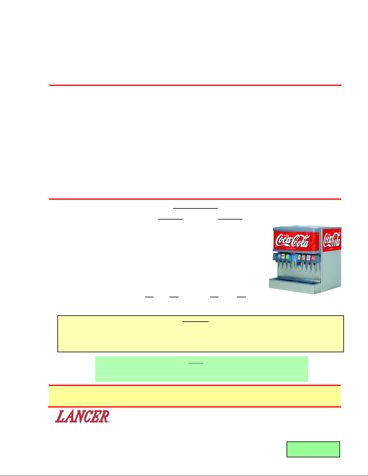
INSTALLATION AND SERVICE MANUAL
FOR
ICE BEVERAGE DISPENSERS, IBD22 - IBD30
LANCER SERIES 4500
85-4526H ICE BEVERAGE DISPENSER, 22 INCH WIDE, 6V, 115V/60Hz
85-4536H ICE BEVERAGE DISPENSER, 22 INCH WIDE, 6V, 230V/50-60Hz
85-4566H ICE BEVERAGE DISPENSER, 22 INCH WIDE, 6V, PRE-MIX, 115V/60Hz
85-4548N ICE BEVERAGE DISPENSER, 30 INCH WIDE, 8V, 115V/60Hz, PELLET ICE ONLY
85-4548H ICE BEVERAGE DISPENSER, 30 INCH WIDE, 8V, 115V/60Hz
85-4558H ICE BEVERAGE DISPENSER, 30 INCH WIDE, 8V, 230V/50-60Hz
85-4541H ICE BEVERAGE DISPENSER, 30 INCH WIDE, 10V, 115V/60Hz
85-4420H ICE DISPENSER, 22 INCH WIDE, 115V/60Hz
85-4430H ICE DISPENSER, 22 INCH WIDE, 230V/50-60Hz
85-4440H ICE DISPENSER, 30 INCH WIDE, 115V/60Hz
85-4450H ICE DISPENSER, 30 INCH WIDE, 230V/50-60Hz
This manual supersedes Installation and Service Manual 28-0255/09, Dated 02/15/06,
and is being published on the Lancer Web Site only.
DATE: 03/06/06
P.N. 28–0255/10
• FAX ENGINEERING: • 210-310-7096 •
• "Lancer" is the registered trademark of Lancer •
• Copyright — 2006 by Lancer, all rights reserved. •
6655 LANCER BLVD. • SAN ANTONIO, TEXAS 78219 USA • (210) 310-7000
FAX SALES
• NORTH AMERICA – 210-310-7245 • INTERNATIONAL SALES – 210-310-7242 • CUSTOMER SERVICE – 210-310-7242 •
• LATIN AMERICA – 210-310-7245 • EUROPE – 32-2-755-2399 • PACIFIC – 61-8-8268-1978 •
NOTE
Lancer does not recommend the use of shaved, flake, nugget, or pellet ice in
dispensers not properly equipped to do so.
Page 2

TABLE OF CONTENTS
SPECIFICATIONS ......................................................................................................................................cover
TABLE OF CONTENTS .....................................................................................................................................1
1. INSTALLATION ...........................................................................................................................................1
1.1 RECEIVING........................................................................................................................................1
1.2 UNPACKING ......................................................................................................................................1
1.3 SELECTING COUNTER LOCATION.................................................................................................1
1.4 INSTALLING THE DISPENSER.........................................................................................................3
1.5 ADJUSTING THE ICE FLOW REGULATOR (230 VOLT UNITS ONLY)...........................................3
2. CLEANING AND SANITIZING INSTRUCTIONS ........................................................................................4
2.1 GENERAL INFORMATION ................................................................................................................4
2.2 REQUIRED CLEANING EQUIPMENT...............................................................................................4
2.3 DAILY CLEANING..............................................................................................................................5
2.4 ICE BIN CLEANING – START UP AND MONTHLY ..........................................................................5
2.5 CLEANING AND SANITIZING BEVERAGE COMPONENTS - FIGAL SYSTEMS............................5
2.6 CLEANING AND SANITIZING BEVERAGE COMPONENTS - BAG-IN-BOX SYSTEMS.................6
3. TROUBLESHOOTING.................................................................................................................................7
4. LIGHT EMITTING DIODES ......................................................................................................................7-8
5. AUTOMATIC AGITATION AND LOW ICE ALARM CONTROL..................................................................8
6. ILLUSTRATIONS, PARTS LISTINGS, AND WIRING DIAGRAMS............................................................9
6.1 DECALS AND LABELS.................................................................................................................9-10
6.2 FINAL ASSEMBLY, POST-MIX IBD AND ICE DISPENSER .......................................................11-12
6.3 FAUCET PLATE AND ICE CHUTE SUB-ASSEMBLY, POST-MIX, IBD.....................................13-14
6.4 ELECTRICAL BOX AND GEAR MOTOR SUB-ASSEMBLY, POST-MIX, IBD............................15-16
6.5 FINAL ASSEMBLY, PRE-MIX, IBD22 .........................................................................................17-18
6.6 FAUCET PLATE AND ICE CHUTE SUB-ASSEMBLY, PRE-MIX, IBD22 ...................................19-20
6.7 ELECTRICAL BOX AND GEAR MOTOR SUB-ASSEMBLY, PRE-MIX, IBD22..........................21-22
6.8 PELLET ICE DISPENSER SUB-ASSEMBLY, IBD30.......................................................................23
6.9 WIRING DIAGRAM - 115V/60HZ.....................................................................................................24
6.10 WIRING DIAGRAM - 230V/50-60HZ ...............................................................................................25
6.11 AGITATION - CONTROLS, EXPANDED VIEW ...............................................................................26
6.12 RECOMMENDED PLUMBING, SIX (6) VALVE ...............................................................................27
6.13 RECOMMENDED PLUMBING, EIGHT (8) VALVE ..........................................................................27
1
1. INSTALLATION
1.1 RECEIVING
Each unit is completely tested under operating conditions and thoroughly inspected before shipment.
At time of shipment the carrier accepts the unit, and any claim for damage must be made with the
carrier. Upon receiving units from the delivering carrier, carefully inspect carton for visible indication
of damage. If damage exists, have carrier note same on bill of lading and file claim with carrier.
1.2 UNPACKING
A. Set shipping carton upright on the floor.
B. Cut band and remove.
C. Open top of carton and remove interior packing.
D. Lift carton up and off of the dispenser.
E. Remove wood shipping base from the bottom of the dispenser. (Support dispenser while
removing shipping base to prevent damage to the dispenser.)
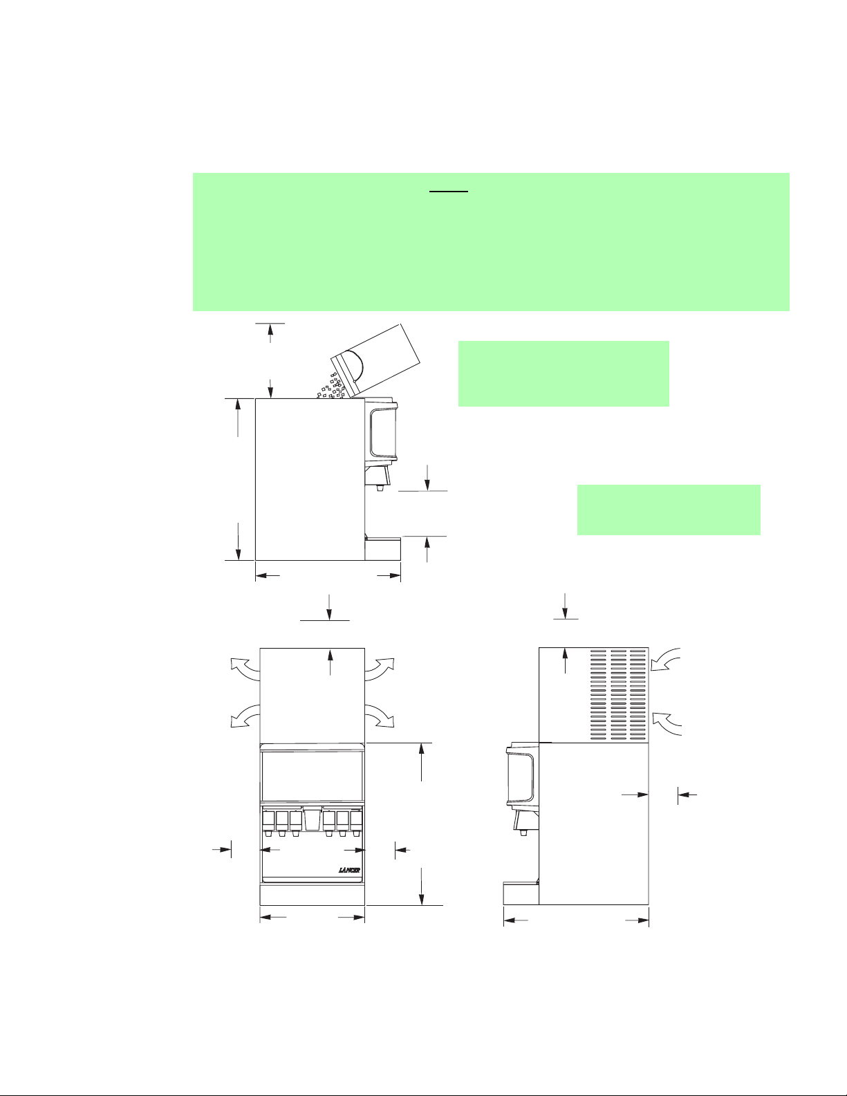
1.3 SELECTING COUNTER LOCATION (SEE FIGURE 1)
W
ARNING
THIS APPLIANCE MUST BE EARTHED. THIS DISPENSER MUST BE ELECTRICALLY
GROUNDED TO AVOID DANGER TO THE OPERATOR. THE POWER CORD PROVIDED HAS
A THREE PRONG GROUNDED PLUG. IF A THREE HOLE GROUNDED ELECTRICAL OUTLET
IS NOT AVAILABLE, USE AN APPROVED METHOD OF INSURING A PROPER GROUND TO
THE DISPENSER.
A. Select a location close to a properly grounded electrical outlet, convenient to an open type drain,
access for soda, water, and syrup lines, and sufficient clearance for air circulation.
1. If at all possible, location should be away from direct sunlight or other heat sources.
Page 3
2
NOTE: 22 Inch wide unit is
displayed in this
illustration.
Figure 1
C. Location must insure sufficient clearance on sides, top and back of unit is provided for
ventilation and air circulation (see Figure 1).
D. Additionally, if an ice maker is not top mounted on the unit, sufficient clearance should be
provided [a minimum of 16 inches (40.6 cm) is recommended] to allow filling the unit with ice
2. Connecting lines may be run through access in back of the unit or extend down through a
counter cut out.
3. The counter must support the weight of the dispenser, ice, and possibly an ice maker. To tal
weight may exceed 800 lbs (363.6 kg).
B. Unit may be installed directly on the countertop or on legs supplied with the unit. If installed
directly on the counter, the unit must be sealed to the countertop. If an ice maker is to be
mounted on top of dispenser, do not install dispenser on legs.
NOTE
Water pipe connections and fixtures directly connected to a potable water supply must all be
sized, installed, and maintained according to Federal, State, and Local laws.
The water supply must be protected by means of an air gap, a backflow prevention device
(located upstream of the CO2 injection system) or another approved method to comply with
NSF standards. A backflow prevention device must comply with ASSE and local standards.
It is the responsibility of the installer to ensure compliance.
NOTE:
Please refer to specific icemaker
model for proper air intake/exhaust
ventilation with Lancer units.
SUFFICIENT CLEARANCE FOR
FILLING MANUALLY WITH ICE,
WHEN ICE MAKER NOT USED
34" (864 mm)
30 1/2" (775 Mm)
MINIMUM of 6" (152 mm)
clearance above ice maker
AIR
OUT
OUT
AIR
9 3/4" (248 Mm)
DISPENSE HEIGHT
OUT
AIR
AIR
OUT
MINIMUM of 6" (152 mm)
clearance above ice maker
IN
AIR
AIR
IN
I C E
PUSH
6" (152 mm) clearance
22" (559 mm)
34" (864 mm)
6" (152 mm) clearance
30 1/2" (775 mm)
wall clearance
MINIMUM of 6" (152 mm)
Page 4
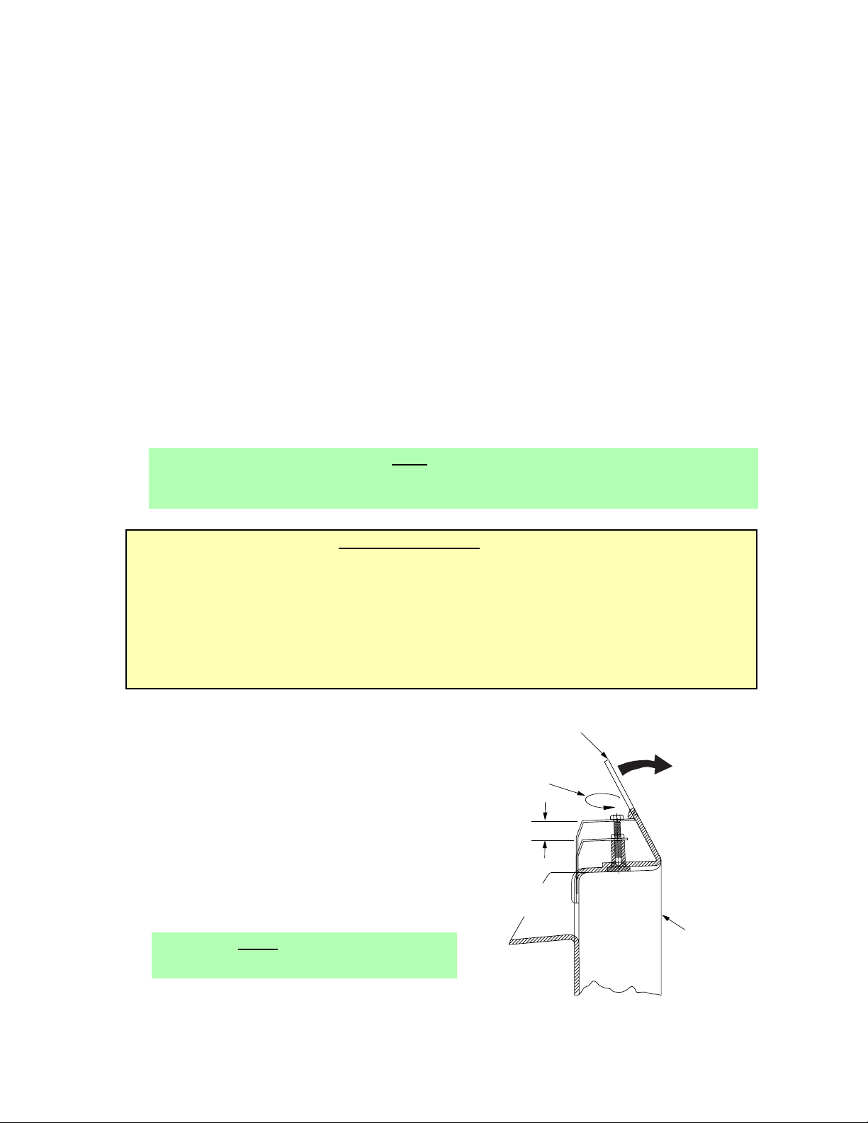
Figure 2
from a five (5) gallon (19 liter) container (see Figure 1).
1.4 INSTALLING THE DISPENSER
A. Remove Cup Rest, Drip Tray, Splash Plate, and Top Cover.
B. Remove Cover Plate at rear of unit if not a through the counter installation.
C. Connect soda and water supply lines to 3/8 inch barb fittings at the front of the unit. Check for
leaks. (If dispenser is to operate with all soda valves, connect water line into one of the soda
supply lines.)
D. Connect syrup supply lines to the 3/8 inch barb inlet fittings at the front of the unit. Check for
leaks.
E. Uncoil drain hose from Cold Plate drain and extend to an open type drain.
F. Install Drip Tray and extend hose to open type drain.
G. Both drain lines must be insulated with a closed cell insulation. Insulation must cover the entire
length of the drain hose, including fittings. The drain should be installed in such a manner that
water does not collect in sags or other low points, as condensation will form.
H. Install Cup Rest and Splash Plate.
I. Connect Power Cord to grounded electrical outlet.
J. Test Motor operation by pushing Ice Chute.
K. Clean and sanitize dispenser (see Section 2).
L. Fill unit approximately half full with ice. Push Chute and check for ice delivery.
M. Finish filling unit with ice.
N. Install Top Cover.
NOTE
Lancer does not recommend the use of shaved, flake, nugget, or pellet ice in dispensers not properly
equipped to do so.
O. Set brix ratio for beverage dispensing valves according to manufacturer’s instructions.
IMPORT
ANT NOTICE
WHEN INSTALLING AN ICEMAKER ON AN IBD UNIT, A BIN THERMOSTAT OR OTHER MEANS
OF CONTROLLING THE ICE LEVEL MUST BE INSTALLED. FAILURE TO DO SO COULD
RESULT IN DAMAGE TO THE DISPENSING MECHANISM AND VOID THE WARRANTY.
DURING THE AUTOMATIC AGITATION CYCLE AND/OR WHILE DISPENSING ICE, THERE
MUST BE ADEQUATE ROOM BETWEEN THE TOP OF THE ICE LEVEL AND THE BOTTOM OF
THE ICEMAKER SO THAT THE ICE CAN MOVE WITHOUT OBSTRUCTION.
CONTACT YOUR ICEMAKER SUPPLIER FOR INFORMATION ON PROPER BIN THERMOSTAT.
3
Turn Screw to Adjust
Adjustment
To Ice
ICE
CUT AWAY VIEW
Access Slot in
If necessary, bend
Wheel
Clockwise to Close
Counter Clockwise to Open
Plastic Wheel Shroud
slightly forward for
easier installation.
for adjustment
Use the access slot
Shroud
Dispensing Chute
SIDE
1.5 ADJUSTING THE ICE FLOW REGULATOR
(230 VOLT UNITS ONLY) (SEE FIGURE 2)
The Regulator Door Assembly (PN 82-2904) can
regulate the dispensed ice flow. Installation of an
Ice Flow Regulator is NOT necessary for the
dispensing of ice. This IBD unit will dispense ice
unrestricted.
A. Remove Bin Lids.
B. Adjust Ice Regulator to desired position by
turning the nut screw clockwise to close, or
counter clockwise to open, with the use of a nut
driver or a socket wrench (see Figure 2).
NOTE
Total adjustment: 1/2 inch.
C. Reinstall bin lids.
Page 5

4
2. CLEANING AND SANITIZING INSTRUCTIONS
2.1 GENERAL INFORMATION
A. Lancer equipment (new or reconditioned) is shipped from the factory cleaned and sanitized in
accordance with NSF guidelines. This equipment must be cleaned and sanitized after
installation is complete, and the operator of the equipment must provide continuous
maintenance as required by this manual and/or state and local health department guidelines to
ensure proper operation and sanitation requirements are maintained.
NOTE
The cleaning and sanitizing procedures provided herein pertain to the Lancer equipment
identified by this manual. If other equipment is being cleaned, follow the guidelines established
for that equipment.
B. Cleaning and sanitizing should be accomplished only by trained personnel. Sanitary gloves are
to be used during cleaning and sanitizing operations. Applicable safety precautions must be
observed. Instruction warnings on the product being used must be followed.
C. Water lines are not to be disconnected during the cleaning and sanitizing of syrup lines to avoid
contamination.
D. Do NOT use strong bleaches or detergents. They tend to discolor and/or corrode various
materials.
E. Do NOT use metal scrapers, sharp objects, steel wool, scouring pads, abrasives, solvents, etc.,
on the dispenser.
F. Do NOT use hot water above 140°F (60°C). This may damage certain materials.
2.2 REQUIRED CLEANING EQUIPMENT
A. Cleansers (for example, Ivory Liquid, Calgon, etc.) mixed with clean, potable water at a
temperature of 90 to 110 degrees Fahrenheit should be used to clean equipment. The mixture
ratio, using Ivory Liquid, is one (1) ounce of cleanser to two (2) gallons of water. A minimum of
five (5) gallons of cleaning mixture should be prepared. Any equivalent cleanser may be used
as long as it provides a caustic based, non-perfumed, easily rinsed mixture containing at least
two (2) percent sodium hydroxide (NaOH). Rinsing must be thorough and use clean, potable
water which is also at a temperature of 90° to 110°F.
NOTE
Extended lengths of product lines may require that an additional volume of cleaning solution be
prepared.
B. Sanitizing solutions should be prepared in accordance with the manufacturer’s written
recommendations and safety guidelines. The solution must provide 200 parts per million (PPM)
available chlorine. A minimum of five (5) gallons of sanitizing solution should be prepared. Any
sanitizing solution may be used as long as it is prepared in accordance with the manufacturer’s
written recommendations and safety guidelines, and provides 200 parts per million (PPM)
available chlorine. Sanitizing solution is to be purged from line(s) and equipment by flushing
with product only until there is no after taste. Do not rinse with water.
NOTE
Please note that a fresh water rinse cannot follow sanitization of equipment. Purge only with
the end use product until there is no after taste in the product. This is an NSF requirement.
Extended lengths of product lines may require that an additional volume of sanitizing solution
be prepared.
C. Other:
(1) Clean cloth towels.
(2) Bucket.
(3) Small brush (PN 22-0017) - included with installation kit.
(4) Extra nozzle.
(5) Sanitary gloves.
Page 6

2.3 DAILY CLEANING
Using a mild detergent solution, clean Top Cover and all exterior stainless steel surfaces. Clean
exterior of dispensing valves and ice chute. Remove Cup Rest. Clean Drip Tray and Cup Rest, and
replace Cup Rest. Wipe clean all splash areas using a damp cloth soaked in cleaning solution.
Clean beverage valves as specified by the valve manufacturer.
2.4 ICE BIN CLEANING - START UP AND MONTHLY
A. Disconnect Dispenser from power source.
B. Remove Top Cover.
C. Remove Agitator Pin from Agitator Shaft. Slide Agitator Shaft rearward out of Motor Shaft and
pull out of rear Bearing to remove.
D. Remove Dispensing Wheel from Motor Shaft by sliding rearward.
E. Remove Dispensing Wheel Shroud.
F. Remove Splash Plate Assembly by lifting it up and out from the dispenser face.
G. Using cleaning solution, described in Section 2.2, and a clean cloth or soft brush, clean all
removable parts, sides of Ice Bin, Ice Chute, and surface of aluminum casting.
H. Repeat Step G for all exterior surfaces of the dispenser.
I. Using hot water, thoroughly rinse away the cleaning solution.
J. Wearing sanitary gloves, soak a clean cloth towel in sanitizing solution, described in Section 2.2,
and wash all surfaces of removable parts, sides of Ice Bin, Ice Chute, and surface of aluminum
casting.
K. Repeat Step J for all metal and plastic surfaces (but not labels) of the dispenser exterior.
L. Wearing sanitary gloves, reassemble all removable parts.
M. Fill Unit with ice and replace Top Cover.
NOTE
Lancer does not recommend the use of shaved, flake, nugget, or pellet ice in dispensers not properly
equipped to do so.
N. Reconnect Dispenser to power source.
2.5 CLEANING AND SANITIZING BEVERAGE COMPONENTS - FIGAL SYSTEMS
NOTE
Extended lengths of product lines may require more time for flushing and rinsing lines than
stated below.
A. Disconnect syrup lines from syrup containers (for example, quick disconnects, figal containers,
etc.).
B. Connect hose half of syrup line to a syrup tank filled with clean, potable, room temperature
water. Connect CO
2 supply hose to tank and pressurize.
C. Activate valve until water is dispensed. Flush and rinse line and fittings for a minimum of
60 seconds to remove all traces of residual product.
W
ARNING
TO AVOID POSSIBLE PERSONAL INJURY OR PROPERTY DAMAGE, DO NOT ATTEMPT TO
REMOVE SYRUP TANK COVER UNTIL CO
2 PRESSURE HAS BEEN RELEASED FROM TANK.
D. Disconnect CO2 supply hose from the water filled syrup tank.
E. Following the instructions as described in Section 2.2 above, mix appropriate amount of
cleaning solution. Fill a tank with this solution. Connect hose half of syrup line to the tank.
Connect CO
2 supply hose to tank and pressurize.
F. Activate valve and draw cleaning solution through lines for a minimum of 60 seconds. This will
ensure line is flushed and filled with cleaning solution. Allow line to stand for at least
30 minutes.
G. Disconnect CO
2 supply hose from the tank.
H. Connect hose half of syrup line to a tank filled with clean, potable, water at a temperature of 90°
to 110°F. Connect CO
2 supply hose to tank and pressurize.
I. Activate valve to flush and rinse line and fittings for a minimum of 60 seconds to remove all
traces of cleaning solution. Continue rinsing until testing with phenolpthalein shows that the
5
Page 7

6
rinse water is free of residual detergent.
J. Disconnect CO
2 supply hose from the tank.
K. Following the instructions as described in 2.2 above, mix appropriate amount of sanitizing
solution. Fill a tank with this solution. Connect hose half of syrup line to the tank. Connect CO
2
supply hose to tank and pressurize.
L. Activate valve and draw sanitizing solution through line for a minimum of 60 seconds. This will
ensure line is flushed and filled with sanitizing solution. Allow line to stand for at least
30 minutes.
M. Disconnect CO
2 supply hose from the tank.
N. Reconnect syrup lines to syrup containers (for example, quick disconnects, figal containers, etc.)
and ready unit for operation.
O. Draw drinks to refill lines and flush the sanitizing solution from the dispenser.
NOTE
Please note that a fresh water rinse cannot follow sanitization of equipment. Purge only with the
end use product until there is no after taste in the product.
P. Test dispenser in normal manner for proper operation. Taste dispensed product to ensure there
is no off-taste. If off-taste is found, additional flushing of syrup system may be required.
Q. Repeat cleaning, rinsing, and sanitizing procedures for each valve and each circuit.
2.6 CLEANING AND SANITIZING BEVERAGE COMPONENTS - BAG-IN-BOX SYSTEMS
NOTE
Extended lengths of product lines may require more time for flushing and rinsing lines than
stated below.
A. Disconnect syrup quick disconnect coupling from syrup packages and connect coupling to a bag
valve removed from an empty Bag-in-Box (BIB) package.
B. Place syrup inlet line in a clean container filled with clean, potable, room temperature water.
C. Activate valve until water is dispensed. Flush and rinse line and fittings for a minimum of
60 seconds to remove all traces of residual product.
D. Following the instructions as described in 2.2 above, mix appropriate amount of cleaning
solution in a clean container. Place syrup inlet line in container filled with cleaning solution.
E. Activate valve and draw cleaning solution through lines for a minimum of 60 seconds. This will
ensure line is flushed and filled with cleaning solution. Allow line to stand for at least 30 minutes.
F. Place syrup inlet line in a clean container filled with clean, potable, water at a temperature of 90
°
to 110°F.
G. Activate valve to flush and rinse line and fittings for a minimum of 60 seconds to remove all traces
of cleaning solution. Continue rinsing until testing with phenolpthalein shows that the rinse water
is free of residual detergent.
H. Following the instructions as described in 2.2 above, mix appropriate amount of sanitizing
solution in a clean container. Place syrup inlet line in container filled with sanitizing solution.
I. Activate valve and draw sanitizing solution through line for a minimum of 60 seconds. This will
ensure line is flushed and filled with sanitizing solution. Allow line to stand for at least
30 minutes.
J. Remove bag valve from quick disconnect coupling and reconnect syrup inlet line to syrup
package. Ready unit for operation.
K. Draw drinks to refill lines and to flush the chlorine sanitizing solution from the dispenser.
NOTE
Please note that a fresh water rinse cannot follow sanitization of equipment. Purge only with the
end use product until there is no after taste in the product. This is an NSF requirement.
L. Test dispenser in normal manner for proper operation. Taste dispensed product to ensure there
is no off-taste. If off-taste is found, additional flushing of syrup system may be required.
M. Repeat cleaning, rinsing, and sanitizing procedures for each valve and each circuit.
Page 8

7
3. TROUBLESHOOTING
TROUBLE CAUSE REMEDY
3.1 Push Chute and A. Dispenser not connected to A. Connect Dispenser to power
nothing happens. power source. source.*
B. Microswitch defective. B. Replace Microswitch.*
C. Wiring Harness not plugged in. C. Plug in Wiring Harness.*
D. PC Board defective. D. Replace PC Board.*
3.2 Push Chute, Trap Door A. Wiring Harness not plugged in. A. Plug in Wiring Harness.*
opens but Motor does B. PC Board defective. B. Replace PC Board.*
not run. C. Motor defective. C. Replace Motor.*
3.3 Push Chute, Motor A. Solenoid not connected to A. Connect Solenoid to PC board.*
runs but Trap Door PC Board.
does not open. B. Solenoid defective. B. Replace Solenoid.*
C. PC Board defective. C. Replace PC Board.*
3.4 Push Chute, Trap Door A. Dispenser is out of ice. A. Fill unit with ice.
opens, Motor runs, B. Agitator Pin is missing or B Replace Agitator Pin.
but no ice dispenses. damaged.
3.5 Valves do not operate. A. Keyswitch is off. A. Turn Keyswitch on.
B. Transformer tripped. B. Reset Transformer.
C. Unit not plugged in. C. Plug in Dispenser.*
3.6 Water in Ice Bin. A. Coldplate Drain is obstructed. A. Remove Drain Hose and
90 degree fitting to obtain
access to Drain.
B. Drain Hose is kinked. B. Replace Drain Hose.
* Light Emitting Diodes (LEDs) are provided on the PC Board to aid in troubleshooting electrical
difficulties. Referring to the wiring diagram included in this manual (also affixed to the electrical box
cover), the following information in Section 4 can be obtained from the LEDs.
4. LIGHT EMITTING DIODES (LEDS)
4.1 LED D3
This light is on when the ice dispense switch is activated. If the chute is depressed and the light does
not turn on, check to see if the wire harness is connected or if the dispense switch is defective.
4.2 LED D4
This light is used on units with lid interlock switches. On the 4500 series ice-beverage dispenser, this
light should always be lit. If it is not, check the Lid Interlock Jumper (black wire with 4 pin white
connector).
4.3 LED D5
This light is on when +5VDC is present at the circuit board. It should be lit whenever the unit is
connected to a power source. If the light is off, check to see if the internal circuit breaker on the
transformer has tripped. If it has tripped, it can be reset by depressing the switch on the top of the
transformer.
4.4 LED D6
This light is on when +32VDC is present at the circuit board. It should be lit whenever the unit is
connected to a power source. If the light is off, check to see if the internal circuit breaker on the
transformer has tripped. If it has tripped, it can be reset by depressing the switch on the top of the
transformer.
4.5 LED D7
This light flashes when there is no ice between the sensors in the ice bin. If the bin is empty and the
light is not flashing, check all wiring harnesses.
Page 9

4.6 LED D8
This light is on when the solenoid is activated. When the chute is depressed, this light should turn on.
If it does not, check to see if the solenoid leads are connected to the PC board or damaged, check
continuity of solenoid. Replace if defective.
4.7 LED D9
This light is on when the motor is activated. When the chute is depressed, this light should turn on. If
it does not, check to see if the motor harness is connected to the PC board or damaged, check
continuity of motor harness and motor. Replace if defective.
5. AUTOMATIC AGITATION AND LOW ICE ALARM CONTROL
W
ARNING
THIS UNIT IS EQUIPPED WITH AUTOMATIC AGITATION. IT MAY ACTIVATE UNEXPECTEDLY. DO
NOT PLACE HANDS, OR FOREIGN OBJECTS IN THE ICE STORAGE COMPARTMENT.
WHEN UNIT IS BEING SERVICED, CLEANED, OR SANITIZED, UNPLUG DISPENSER FROM THE
POWER SOURCE.
Each Series 4500 ice beverage dispenser is equipped with automatic agitation for the ice bin. The unit is
shipped with timing set at two (2) seconds ON every 60 minutes. Referring to the tables on the wiring
diagram included in this manual (also affixed to the electrical box cover), the automatic agitation timing can
be changed as follows. A set of DIP switches is provided to control the timing and low ice control.
NOTE:
Dispensers using pellet ice must have the automatic agitation settings adjusted to four (4) seconds ON
every 150 minutes. See Section 6.11.
5.1 DIP#1
This switch controls the low ice indicator light. With the switch in the ON position, the light operates
when a low ice condition exists. In the OFF position, the light is turned off. The unit is shipped with
the light switch in the ON position.
5.2 DIP#2
This switch controls the low ice audible alarm. With the switch in the ON position, the alarm operates
when a low ice condition exists. In the OFF position, the alarm is turned off. The unit is shipped with
the alarm switch in the OFF position.
5.3 DIP#3 & #4
These switches control the ON time for automatic agitation. By referring to the table and setting the
switches as shown, ON times from one (1) second to four (4) seconds [in one (1) second increments]
can be obtained. EXAMPLE: For three (3) seconds ON time, switch 3 should be in the ON position,
and switch 4 should be in the OFF position. The unit is shipped with two (2) seconds ON time.
5.4 DIP#5 through #8
A. These switches control the OFF time for automatic agitation. By referring to the table and setting
the switches as shown, OFF times from 10 minutes to 150 minutes (in 10 minute increments) can
be obtained. EXAMPLE: For 40 minute OFF time, switch 5 should be in the OFF position, switch
6 should be in the ON position, switch 7 should be in the OFF position, and switch 8 should be in
the OFF position. The unit is shipped with 60 minute OFF time.
B. To turn the agitation completely off, set switches 5 through 8 all OFF.
NOTES:
8
Page 10

6. ILLUSTRATIONS AND PARTS LISTINGS
6.1 DECALS AND LABELS
9
E
L
D
E
C
H
A
T
A
R
Z
U
IC
N
A
N
I
R
A
T
D
L
G
M
S
O
D
A
Y
I
U
H
S
E
S
A
C
S
O
E
C
O
C
R
M
T
R
N
V
I
K
N
V
O
I
C
A
H
E
V
T
C
I
N
I
E
A
T
N
G
Z
U
P
G
O
A
N
O
P
R
E
W
R
X
C
D
E
A
P
L
R
R
E
E
C
B
A
T
E
T
N
S
E
F
I
N
O
D
G
L
R
Y
E
U
N
I
T
1
.
12
11
2, 3, 4
5
6
10
7
8
9
Page 11

10
Item Part
No. Description
- 85-4526H-100 IBD22H, Series 4500,
115V/60Hz, 6 LEV®
- 85-4548H-100 IBD30H, Series 4500,
115V/60Hz, 8 LEV
®
- 85-4536H-100 IBD22H, Series 4500,
230V/50-60Hz, 6 LEV®
- 85-4558H-100 IBD30H, Series 4500,
230V/50-60Hz, 8 LEV®
- 85-4541H-100 IBD30H, Series 4500,
115V/60Hz, 10 LEV
®
1 06-1139 Label, Warning, Lid, IBD
2 06-2057/01 Panel, Graphic, IBD22,
Round
- 06-2072/01 Panel, Graphic, IBD30,
Round
3 27-0069 Diffuser Lens, IBD22
- 27-0070 Diffuser Lens, IBD30
4 27-0063 Clear Lens, IBD22
- 27-0064 Clear Lens, IBD30
5 06-1184/01 Label, Cleaning,
Merchandiser
6 06-1182/04 Label, Wiring Diagram,
115V, IBD (See Section 6.9)
- 06-1521/02 Label, Wiring Diagram,
230V, IBD (See Section
6.10)
7 06-1181/02 Label, Plumbing Diagram,
IBD22 (See Section 6.12)
- 06-2226 Label, Plumbing Diagram,
IBD30 (See Section 6.13)
8 06-1522 Label, Low Ice, IBD
9 06-1207 Label, Cold Plate Cleaning,
IBD
10 06-2058/01 Decal, Wrapper, Side, IBD,
Round
11 06-1183 Decal, Cleaning, Hopper,
IBD
12 06-2059/01 Decal, Wrapper, Back,
IBD22, Round
- 06-2073/01 Decal, Wrapper, Back,
IBD30, Round
- 12-0193 Ice Out Indicator
6.1 DECALS AND LABELS (CONTINUED)
Page 12

6.2 FINAL ASSEMBLY, POST-MIX IBD AND ICE DISPENSER
11
NOTE:
TO ADJUST ICE FLOW
REGULATOR, SEE SECTION 1.5
(230 VOLT ONLY)
6
7
10
8
9
11
9
1
5
2
4
3
13
1
12
14
15
Page 13

Item Part No. Description
- 85-4526H IBD22H, Series 4500,
115V/60Hz,6 Valve
- 85-4548H IBD30H, Series 4500,
115V/60Hz,8 Valve
- 85-4536H IBD22H, Series 4500,
230V/50-60Hz,6 Valve
- 85-4558H IBD30H, Series 4500,
230V/50-60Hz,8 Valve
- 85-4541H IBD30H, Series 4500,
115V/60Hz,10 Valve
1 05-1309/02 Wheel Shroud, IBD22
- 82-1892/01 Wheel Shroud Assy, IBD22,
Mod (230V ONLY)
- 05-1310/02 Wheel Shroud, IBD30
- 82-1893 Wheel Shroud Assy, IBD30,
Mod (230V ONLY)
2 03-0368 Retainer, RUE-14-S
3 23-1373 Agitator Assy, HEX, IBD
(115V)
- 23-1355 Agitator Assy, IBD
(230V Only)
4 10-0762 Pin, Agitator, IBD, Single
Retainer
5 82-3556 Dispensing Wheel Assy, HEX,
IBD (115V)
- 82-3413 Dispensing Wheel Assy, IBD
(230V Only)
6 05-1467 Lid, Back, IBD22, Round
- 05-1606 Lid, Back, IBD30, Round
7 05-1476 Lid, Front, IBD, Round
8 82-2630 Merchandiser Assy, IBD,
22 Inch, Round
- 82-2641 Merchandiser Assy, IBD,
30 Inch, Round
6.2 FINAL ASSEMBLY, POST-MIX IBD AND ICE DISPENSER (CONTINUED)
12
9 03-0300 Wire Clip, Adhesive
10 23-1038/01 Drain, Spider, IBD
11 03-0049 Clip, Cord
12 12-0146/01 Lamp, 18 Inch, 15W, T8
13 30-5951/03 Plate, Splash, IBD, 22 Inch
Wide (Before November 19,
2001)
30-8466 Plate, Splash, IBD, 22 Inch
Wide (After November 19,
2001)
- 30-5904/02 Plate, Splash, IBD, 30 Inch
Wide (Before November 19,
2001)
- 30-8564 Plate, Splash, IBD, 30 Inch
Wide (After November 19,
2001)
14 82-1535-SP Drip Tray Assy, IBD, 22 Inch
Wide (Before November 19,
2001)
82-3175-SP Drip Tray Assy, IBD, 22 Inch
Wide (After November 19,
2001)
- 82-1532-SP Drip Tray Assy, IBD, 30 Inch
Wide (Before November 19,
2001)
82-3177-SP Drip Tray Assy, IBD, 30 Inch
Wide (After November 19,
2001)
15 04-0559 Cap, Protective, Vinyl,
VC-375-8
Item Part
No. Description
Page 14

13
6.3 FAUCET PLATE AND ICE CHUTE SUB-ASSEMBLY, POST-MIX, IBD
10
9
8
6
11
21
7
5
4
3
2
1
TO TRANSFORMER
P
A
R
W
IE
T
TO KEY
WHITE
BLACK
P
A
R
W
IE
T
A
R
W
IE
T
SWITCH
BLACK
BLACK
P
A
R
W
IE
T
P
15
14
13
9
12
Page 15

Item Part No. Description
- 85-4526H IBD22H, Series 4500,
115V/60Hz, 6 Valve
- 85-4548H IBD30H, Series 4500,
115V/60Hz, 8 Valve
- 85-4536H IBD22H, Series 4500,
230V/50-60Hz, 6 Valve
- 85-4558H IBD30H, Series 4500,
230V/50-60Hz, 8 Valve
- 85-4541H IBD30H, Series 4500,
115V/60Hz,10 Valve
1 04-0308 Screw, 10 - 32 X 0.438
2 82-1559 Faucet Plate Assy, IBD22
- 82-1631 Faucet Plate Assy, IBD30
- 82-1938 Faucet Plate Assy, 10
Valve, IBD30
3 02-0005 O-Ring, 2-010
4 06-0877 Label, Ground
5 04-1089 Screw, 10 - 32 X 1.000, RH,
PH/SL
6 04-0553 Screw, 10 - 24 X 1.75, LG.
7 82-3538 Chute Assy, Printed, Small
Dispenser, IBD
8 05-0928/02 Trap Door, IBD
9 04-0504 Screw, 8 - 18 X 0.375, PHD
10 82-1566/01 Solenoid Assy, IBD
6.3 FAUCET PLATE AND ICE CHUTE SUB-ASSEMBLY, POST-MIX, IBD (CONTINUED)
14
A 03-0086 Ring, Retaining (5304-18)
B 04-0328 Washer, Rubber
C 04-0327 Washer, Flat
D 12-0195 Solenoid, D-90
E 30-5165/01 Bracket, Solenoid
F 23-1029 Plunger Assy
G 10-0496 Pin, Solenoid Assy
H 03-0110 Spring, Solenoid
I 03-0111 Ring, Retaining (5133-62)
J 10-0353 Linkage, Door, IBD
K 04-0320 Screw, 8 - 32 X 0.187, PHD
11 82-1551/01 Trim Assy, IBD22, Round
- 82-1618/01 Trim Assy, IBD30, Round
12 30-5876/01 Cover, Electrical Box, IBD
13 30-6145 Lock, Drip Tray, IBD
14 10-0364 Spacer, Drip Tray Lock, IBD
15 04-0529 Screw, 8 - 32 x 0.750, PH
16 10-0732 Shaft, ice Chute Door
17 05-0359 Bushing, Shaft
18 03-0113 Ring, Retaining (5144-12)
19 05-0546 Lever, Door,
20 03-0205 Ring, Retaining (5304-25)
21 12-0244 Ice Door Switch
Item Part No. Description
10
20
K
A
E
G
19
8
B
C
D
F
H
I
J
18
17
16
Page 16

15
6.4 ELECTRICAL BOX AND GEAR MOTOR SUB-ASSEMBLY, POST-MIX, IBD
20
2
21
2
22
23
2
12
24
24
25
2
26
12
11
13
14
15
16
11
17
18
27
19
17
25
26
28
29
4
3
7
29
10
2
5
6
BLACK
WHITE
7
2
6
WHITE
BLACK
2
8
2
2
9
4
3
29
1
2
30
29
Page 17

Item
Part No. Description
- 85-4526H IBD22H, Series 4500,
115V/60Hz, 6 Valve
- 85-4548H IBD30H, Series 4500,
115V/60Hz, 8 Valve
- 85-4536H IBD22H, Series 4500,
230V/50-60Hz, 6 Valve
- 85-4558H IBD30H, Series 4500,
230V/50-60Hz, 8 Valve
- 85-4541H IBD30H, Series 4500,
115V/60Hz,10 Valve
1* 82-1529/02 Electrical Box Assy, IBD,
115V*
- 82-2017/02 Electrical Box Assy, IBD,
230V
- 52-1527 Power Cord Assy, 115V
- 52-2006 Power Cord Assy, 230V
- 21-0769 Power Cord, Europe
- 52-1436/05 PCB Assy, IBD
2 04-0504 Screw, 8 - 18 X 0.375, PHD
3 52-1584 Harness Assy, Light, Black
4 04-0237 Screw, 8 - 32 x 0.250, PH,
MS, SS
5 30-6152 Bracket, Right, Light, IBD
6 11-0295 Socket, 660W/600V MAX
7 52-1583 Harness Assy, Light, White
8 30-6153 Bracket, Left, Light, IBD
9 52-2122 Ballast Assy, Long Lead,
230V, IBD
- 52-1902/01 Ballast Assy, 115V
10 02-0005 O-Ring, 2-010
11 52-2450 Harness Assy, Detector
12 06-2488 Label, Ice Link Tag, IBD
13 02-0406 Seal, Shaft, Motor, IBD
14 82-1324H Tank Assy, Foamed, IBD22
- 82-1606H Tank Assy, Foamed, IBD30
- 82-2225H Tank Assy, Foamed, IBD30,
10 Valve
15 05-1859 Body, Detector, Sensor,
Plug
16 05-1858 Body, Emitter, Sensor, Plug
6.4 ELECTRICAL BOX AND GEAR MOTOR SUB-ASSEMBLY, POST-MIX, IBD (CONTINUED)
16
17 02-0155 O-Ring, 2-015
18 52-2353 Body Assy, Detector, Sensor
19 52-2352 Body Assy, Emitter, Sensor
20 30-8468 Wrapper Assy, IBD22,
Round
- 30-8566 Wrapper Assy, IBD30,
Round
21** 12-0097 Switch, Key Lock**
22 30-6149 Cover, Cut Out, Wrapper,
IBD
23 06-1580 Label, Patent
24 52-2449 Harness Assy, Emitter, IBD
25 07-0211 Washer, Shipping Base
26 04-0203 Screw, 3/8 - 16 X 1.00, FHD
27 90-0756 Shipping Board, IBD,
22 Inch Wide
- 90-0760 Shipping Board, IBD,
30 Inch Wide
28 82-3688 Drive Assy, Motor, HEX,
IBD, 115V
- 82-2018 Drive Assy, Motor, IBD,
230V
29 04-0069 Screw, 10 - 16 X 0.500
30 30-6147 Cover, Motor, IBD
-- 05-1555 Rear Bearing (Not Shown)
REF Ballast Assy Components (Not Shown)
-- 12-0104 Starter, 115VAC, 14-20 WA
-- 12-0194 Starter, Base
REF Electrical Box Assy Components
(Not Shown)
*-- 52-1436/05 PCB Assy, Available as
Spare Part
*-- 25-0039 120V-24V Transformer,
Available as Spare Part
*-- 25-0047 75VA-24V Transformer,
Available as Spare Part
*-- 25-0040 220V-24V Transformer,
Available as Spare Part
**-- 81-0125 Key, Available as Spare Part
Item Part No.
Description
Page 18

6.5 FINAL ASSEMBLY, PRE-MIX, IBD22
17
6
7
8
9
10
5
2
4
3
1
13
11
9
12
14
15
16
Page 19

Item Part No. Description
- 85-4566H IBD22H, Series 4500, 115V,
6 Premix Valve
1 05-1309/02 Wheel Shroud Assy, IBD22
2 03-0368 Retainer, RUE-14-S
3 23-1373 Agitator Assy, HEX, IBD
4 10-0762 Pin, Agitator, HEX, IBD,
Single retainer
5 82-3556 Dispensing Wheel Assy, HEX,
IBD
6 05-1467 Lid, Back, IBD22, Round
7 05-1476 Lid, Front, IBD, Round
8 82-2630 Merchandiser Assy, IBD22,
Round
9 03-0300 Wire Clip, Adhesive
10 23-1038/01 Drain Spider, IBD
11 03-0049 Clip, Cord
12 12-0146/01 Lamp, 18 Inch, 15W, T8
13 82-1929 Cover Assy, Faucet Plate,
IBD, 22 Inch, Pre-Mix
14 82-1535-SP Drip Tray Assy, IBD
(Before November 19, 2001)
82-3175-SP Drip Tray Assy, IBD
(After November 19, 2001)
15 30-7319/02 Plate, Splash, PreMix, IBD22
(Before November 19, 2001)
30-8586 Plate, Splash, PreMix, IBD22
(After November 19, 2001)
16 04-0559 Cap, Protective, Vinyl,
VC-375-8
6.5 FINAL ASSEMBLY, PRE-MIX, IBD22 (CONTINUED)
18
Page 20

6.6 FAUCET PLATE AND ICE CHUTE SUB-ASSEMBLY, PRE-MIX, IBD22
19
9
8
7
6
10
17
5
4
3
2
1
11
8
Page 21

6.6 FAUCET PLATE AND ICE CHUTE SUB-ASSEMBLY, PRE-MIX, IBD22 (CONTINUED)
20
Item Part
No. Description
- 85-4566H IBD22H, Series 4500, 115V,
6 Premix Valve
1 82-1875 Faucet Plate Assy, Premix,
IBD22
2 04-0308 Screw, 10 - 32 X 0.438
3 02-0005 O-Ring, 2-010
4 04-1089 Screw, 10 - 32 x 1.000, RH,
PH/SL
5 82-3538 Chute Assy, IBD
6 04-0553 Screw, 10 - 24 X 1.75, LG
7 05-0928/01 Trap Door, IBD
8 04-0504 Screw, 8 - 18 X 0.375, PHD
9 82-1566/01 Solenoid Assy
A 03-0086 Ring, Retaining (5304-18)
B 04-0328 Washer, Rubber
C 04-0327 Washer, Flat
D 12-0195 Solenoid, D-90
E 30-5165/01 Bracket, Solenoid
F 23-1029 Plunger Assy
G 10-0496 Pin, Solenoid Assy
H 03-0110 Spring, Solenoid
I 03-0111 Ring, Retaining (5133-62)
J 10-0353 Linkage, Door, IBD
K 04-0320 Screw, 8 - 32 x 0.187
10 82-1551/01 Trim Assy, IBD
11 30-5876/01 Cover, Electrical Box, IBD
12 10-0732 Shaft, ice Chute Door
13 05-0359 Bushing, Shaft
14 03-0113 Ring, Retaining (5144-12)
15 05-0546 Lever, Door,
16 03-0205 Ring, Retaining (5304-25)
17 12-0244 Ice Door Switch
Item Part
No. Description
K
A
E
B
C
D
F
G
9
15
16
7
H
I
J
14
13
12
Page 22

6.7 ELECTRICAL BOX AND GEAR MOTOR SUB-ASSEMBLY, PRE-MIX, IBD22
21
19
2
20
2
21
22
2
11
23
23
24
2
25
11
10
12
13
14
15
10
16
17
18
16
26
24
25
27
28
5
9
6
2
BLACK
WHITE
4
3
7
29
7
2
6
WHITE
BLACK
28
8
2
4
3
1
2
29
28
Page 23

6.7 ELECTRICAL BOX AND GEAR MOTOR SUB-ASSEMBLY, PRE-MIX, IBD22 (CONTINUED)
22
Item Part No. Description
- 85-4566H IBD22H, Series 4500, 115V,
6 Premix Valve
1* 82-1879/01 Electrical Box Assy, Pre-Mix,
IBD22*
- 52-1902/01 Ballast Assy, 115V
2 04-0504 Screw, 8 - 18 X 0.375, PHD
3 52-1584 Harness Assy, Light, Black
4 04-0237 Screw, 8 - 32 x 0.250, PH,
MS, SS
5 30-6152 Bracket, Right, Light, IBD
6 11-0295 Socket, 660W/600V MAX
7 52-1583 Harness Assy, Light, White
8 30-6153 Bracket, Left, Light, IBD
9 02-0005 O-Ring, 2-010
10 52-2450 Harness Assy, Detector
11 06-2488 Label, Ice Link Tag, IBD
12 02-0406 Seal, Shaft, Motor, IBD
13 82-1874H Tank Assy, Foamed, Pre-Mix,
IBD22
14 05-1859 Body, Detector, Sensor, Plug
15 05-1858 Body, Emitter, Sensor, Plug
16 02-0155 O-Ring, 2-015
17 52-2353 Body Assy, Detector, Sensor
18 52-2352 Body Assy, Emitter, Sensor
19 30-8468 Wrapper Assy, IBD22, Round
20** 12-0097 Switch, Key Lock**
21 30-6149 Cover, Cut Out, Wrapper, IBD
22 06-1580 Label, Patent
23 52-2449 Harness Assy, Emitter, IBD
24 07-0211 Washer, Shipping Base
25 04-0203 Screw, 3/8 - 16 X 1.00, FHD
26 90-0756 Shipping Board, IBD,
22 Inch Wide
27 82-1556 Drive Assy, Motor, IBD, 115V
28 04-0069 Screw, 10 - 16 X 0.500
29 30-6147 Cover, Motor, IBD
-- 05-1555 Rear Bearing (Not Shown)
Item Part No. Description
REF Ballast Assy Components (Not Shown)
-- 12-0104 Starter, 115VAC, 14-20 WA
-- 12-0194 Starter, Base
REF Electrical Box Assy Components
(Not Shown)
*-- 52-1436/05 PCB Assy, Available as
Spare Part
*-- 25-0039 120V-24V Transformer,
Available as Spare Part
*-- 25-0047 75VA-24V Transformer,
Available as Spare Part
*-- 25-0040 220V-24V Transformer,
Available as Spare Part
**-- 81-0125 Key, Available as Spare
Part
Page 24

6.8 PELLET ICE DISPENSER SUB-ASSEMBLY, IBD30,
CONVERSION KIT, PN 82-3633/01
23
NOTE:
*Item 11 is NOT used on the IBD 4500 Series.
NOTE:
This Conversion Kit is compatible for IBDs
with Serial Numbers 854545H0418M03 and
above
Retrofits for the 30” IBD must include
PN 23-1363 (Item 5).
NOTICE:
The Pellet Ice components listed are to be used ONLY in
conjunction with Nugget, Cubelet, or Chewblet ice.
LANCER makes no warranty of any kind with regard to
these components being used with any other kind of ice.
ITEM
PART NO. DESCRIPTION
QTY
XX 1 02-0577 Grommet, Rubber, 3
G3002
XX 2 03-0368 Retainer, Pin, 1
Agitator, IBD
XX 3 05-2293/01 Ice Shroud, IC 1
XX 4 23-1401 Agitator Assy, 1
Helical, IC, HEX
XR5 23-1363 Extension Assy, 1
4 1/2”, IBD30
XX 6 42-0109 Foamed Cover, 1
Scots/Hoshi,
Pellet Ice
XX 7 30-9446 Adapter, Mech 1
Bin-Stat, Scots
XX 8 82-3538 Ice Chute Assy, 1
IBD30, Pellet Ice
XX 9 82-3651 Dispensing Wheel 1
Assy, Pellet Ice, HEX
XXR10 30-9880 Shield, Nugget Ice, 1
One Piece with Tab
XR11 30-8832/01 Bracket, Valve Plate, 1
FS30
An R next to the Item Number indicates new, revised
or realigned information.
An X in the left columns indicates the parts used in the
installation for an IBD30 Dispenser or an FS30
Dispenser.
IBD30
FS30
LABEL FOR
HOSHIZAKI
ICE MAKER
(TO FRONT OF
DISPENSER)
ATTACH HERE
6 (FOAMED
7
FOR HOSHIZAKI
1
1
2
1
ATTACH HERE
FOR SCOTSMAN
LABEL FOR
TOP COVER
SCOTSMAN
ASSEMBLY)
BIN STAT
ADAPTER,
MECHANICAL
ICE MAKER
(TO FRONT OF
DISPENSER)
5
10
4
11
9
3
8
Page 25

6.9 WIRING DIAGRAM - 115V/60HZ
24
NOT USED ON
PREMIX DISPENSERS
NOTE:
WHITE
VALV E
EMITTER
LOW ICE SENSOR
GREEN
MOTOR
WHITE
BLACK
WHITE
BLACK
BLACK
BLACK
FRONT
FRONT
BACK
BACK
BLACK
BLACK
WHITE
WHITE
WHITE
WHITE
BLACK
BLACK
BLACK
BLACK
BLACK
BLUE
RED
WHITE
YEL
ICE
RED
ALARM
BLUE
J8
WHITE
DETECTOR
LOW ICE SENSOR
J1
ON
BLACK
ICE
DISPENSE
5876
1342
WHITE
SWITCH
J3
J6J5J4
BLACK
BLACK
TRAP
DOOR
SOLENOID
J2
J7
BLACK
WIRING DIAGRAM FOR LANCER ICE DISPENSER WITH LOW ICE SENSING (TYP.)
ELECTRICAL BOX BOUNDARY
RED
BLACK
LOW
LOW
RED
ICE
BLACK
LIGHT
Page 26

6.10 WIRING DIAGRAM - 230V/50-60HZ
25
NOTE: NOT USED ON
PREMIX DISPENSERS
ELECTRICAL BOX BOUNDARY
WHITE
VALV E
EMITTER
LOW ICE SENSOR
GREEN
MOTOR
WHITE
WHITE
BLACK
BLACK
BLACK
BLACK
BLACK
BLACK
WHITE
WHITE
WHITE
WHITE
RED
BLACK
BLUE
YEL
RED
BLUE
WHITE
J1
J8
J4
62431578
ON
J3
J6J5
J2
J7
BLUE
BLUE
RED
RED
BLACK
LIGHT
RED
BLACK
ICE
LOW
ALARM
DETECTOR
BLACK
ICE
DISPENSE
WHITE
SWITCH
TRAP
DOOR
SOLENOID
BLACK
BLACK
RED
WIRING DIAGRAM FOR LANCER ICE DISPENSER WITH LOW ICE SENSING (TYP.)
LOW
ICE
Page 27

6.11 AGITATION - CONTROLS, EXPANDED VIEW
26
876
OFF
ON
=
=
X
FOR PELLET CAPABLE
DISPENSERS ONLY
PELLET ICE SETTING:
AGITATION ON TIME: 4 SEC.
OFF TIME: 150 MIN.
SWITCHES 5-8 : AGITATION "OFF TIME"
CUBE ICE SETTING:
AGITATION ON TIME: 2 SEC.
OFF TIME: 60 MIN.
AGITATION
OFF TIME
8
7
EXPANDED VIEW OF CONTROLS
6
SWITCH NUMBER
5
10 MINUTES
NO AGITATION
O
X
O
O
O
O
O
OO
SWITCH 1 : "LOW ICE" LED INDICATOR
20 MINUTES
30 MINUTES
X
O
X
X
O
O
O
SWITCHES 3-4 : AGITATION "ON TIME"
SWITCH 2 : "LOW ICE" ALARM
40 MINUTES
50 MINUTES
60 MINUTES
O
O
XXX
O
XXXX
O
O
OOO
70 MINUTES
X
O
ON TIME
AGITATION
4
3
SWITCH
NUMBER
90 MINUTES
80 MINUTES
O
X
O
O
OO
X
XXX
ON
1 SECOND
2 SECOND
X
OOO
120 MINUTES
110 MINUTES
100 MINUTES
O
X
O
X
X
O
O
O
X
X
51342
3 SECOND
4 SECOND
X
O
X
X
130 MINUTES
X
O
X
XX
SLIDE SWITCHES:
SLIDE SWITCH UP TO TURN "ON"
SLIDE SWITCH DOWN TO TURN "OFF"
140 MINUTES
150 MINUTES
O
X
X
X
X
X
X
LED
INDICATORS
SWITCH IS CLOSED
D3-ON WHEN ICE DISPENSE
D4-ON WHEN LID IS CLOSED
D5-ON WHEN +5VDC IS AVAILABLE
D6-ON WHEN +32VDC IS
AVAILABLE
D7-FLASHES WHEN ICE IS LOW
SOLENOID IS OPEN
D8-ON WHEN TRAP DOOR
D9-ON WHEN MOTOR IS ON
Page 28

27
Please refer to the Lancer web
site (www.lancercorp.com) for
information relating to Lancer
Installation and Service
Manuals, Instruction Sheets,
Technical Bulletins, Service
Bulletins, etc.
6.12 RECOMMENDED PLUMBING, SIX (6) VALVE
6.13 RECOMMENDED PLUMBING, EIGHT (8) VALVE
RECOMMENDED PLUMBING
6 5 4 321
SODA/WATER #5
SODA/WATER #3,4
SODA/WATER #1,2,6
SYRUP LINES NOT SHOWN
3-2-1 CONFIGURATION
FOR ASSISTANCE CALL 1-800-729-1500
06-1181/02
SYRUP #1
SYRUP #2
SYRUP #3
SYRUP #4
SYRUP #5
SYRUP #6
RECOMMENDED PLUMBING
8 7 6 3 2 1
SODA/WATER #1,2,3
SODA/WATER #4
SODA/WATER #5
SYRUP LINES NOT SHOWN
3-1-1-3 CONFIGURATION
FOR ASSISTANCE CALL 1-800-729-1500
PART NO: 06-2226
5 4
SODA/WATER #6,7,8
SYRUP #1
SYRUP #2
SYRUP #3
SYRUP #4
SYRUP #5
SYRUP #6
SYRUP #7
SYRUP #8
 Loading...