

Page 1
ICE BEVERAGE DISPENSERS, IBD 25 SERIES 4500
Operation Manual
PN: 28-0417/02
Model Number
Lancer Corp.
6655 Lancer Blvd.
San Antonio, Texas 78219
800-729-1500
Technical Support/Warranty: 800-729-1550
custserv@lancercorp.com
lancercorp.com
Manual PN: 28-0417/02
FEB 2006
FOR QUALIFIED INSTALLER ONLY
“Lancer” is the registered trademark of Lancer © 2013 by Lancer, all rights reserved.
Page 2

ABOUT THIS MANUAL
This booklet is an integral and essential part of the product and should be handed over to the operator after the
installation and preserved for any further consultation that may be necessary. Please read carefully the guidelines and
warnings contained herein as they are intended to provide the user with essential information for the continued safe
use and maintenance of the product. In addition, it provides GUIDANCE ONLY to the user on the correct services and
site location of the unit.
The installation and relocation, if necessary, of this product must be carried out by qualied personnel with up-to-date
safety and hygiene knowledge and practical experience, in accordance with current regulations.
TABLE OF CONTENTS
SPECIFICATIONS...............................................................................................................................4
LANCER IBD 4500 Series..................................................................................................................5
PRE-INTALLATION CHECKLIST........................................................................................................5
WARNINGS/CAUTIONS..................................................................................................................6-9
1. INSTALLATION............................................................................................................................10
1.1 RECIEVING.........................................................................................................................10
1.2 UNPACKING.......................................................................................................................10
1.3 SELECTING A LOCATION.............................................................................................10-11
1.4 INSTALLING THE DISPENSER..........................................................................................11
1.5 ADJUSTING THE ICE FLOW REGULATOR (230 VOLT UNITS ONLY)............................12
2. CLEANING AND SANITIZING INSTRUCTIONS........................................................................12
2.1 GENERAL INFORMATION..................................................................................................12
2.2 REQUIRED CLEANING EQUIPMENT...........................................................................12-13
2.3 DAILY CLEANING...............................................................................................................13
2.4 ICE BIN CLEANING - STARTUP AND MONTHLY..............................................................13
2.5 CLEANING AND SANITIZING BEVERAGE COMPONENTS - FIGAL SYSTEMS........13-14
2.7 CLEANING AND SANITIZING BEVERAGE COMPONENTS
BAG-IN-BOX SYSTEMS...............................................................................................14-15
3. TROUBLESHOOTING
3.1 NO PRODUCT WHEN SWITCH IS ACTIVATED (SWITCH PANEL IS NOT LIT) ..............16
3.2 NO PRODUCT WHEN SWITCH IS ACTIVATED (SWITCH PANEL IS LIT).......................16
3.3 PUSH CHUTE; NO RESPONSE........................................................................................16
3.4 PUSH CHUTE, ICE DOOR OPENS BUT MOTOR DOES NOT RUN................................16
3.5 PUSH CHUTE, MOTOR RUNS BUT ICE DOOR DOES NOT OPEN................................16
3.6 PUSH CHUTE, ICE DOOR OPENS, MOTOR RUNS, BUT ICE DOES NOT DISPENSE,
OR ICE IS OF POOR QUALITY..........................................................................................16
3.7 WATER IN ICE BIN.............................................................................................................17
3.8 WATER LEAKAGE AROUND NOZZLE..............................................................................17
3.9 MISCELLANEOUS LEAKAGE............................................................................................17
3.10 NOISY/CAVITATING CARBONATOR PUMP......................................................................17
3.11 INSUFFICIENT SODA FLOW (CARBONATED DRINKS)...................................................17
3.12 INSUFFICIENT WATER FLOW (PLAIN WATER DRINKS).................................................17
3.13 ERRATIC RATIO.................................................................................................................17
3.14 INSUFFICIENT SYRUP FLOW...........................................................................................18
3.15 VALVE WILL NOT SHUT OFF............................................................................................18
3.16 WATER CONTINUALLY LEAKING AT CONNECTIONS.....................................................18
3.17 WATER ONLY DISPENSED, NO SYRUP OR SYRUP
ONLY DISPENSED, NO WATER........................................................................................18
3.18 SYRUP ONLY DISPENSED. NO WATER, BUT CO2 GAS DISPENSED WITH SYRUP...19
3.19 EXCESSIVE FOAMING......................................................................................................19
2
Page 3

3.20 CIRCUIT BREAKER TRIPPING.........................................................................................19
3.21 BIB PUMP DOES NOT OPERATE WHEN DISPENSING VALVE IS OPENED..................20
3.22 BIB PUMP OPERATING, BUT NO FLOW..........................................................................20
3.23 BIB PUMP CONTINUES TO OPERATE WHEN BAG IS EMPTY.......................................20
3.24 BIB PUMP FAILS TO RESTART AFTER BAG REPLACEMENT........................................20
3.25 BIB PUMP FAILS TO STOP WHEN DISPENSING VALVE IS CLOSED............................20
3.26 LOW OR NO CARBONATION............................................................................................20
4. LIGHT EMITTING DIODES (LEDS)............................................................................................21
5. AUTOMATIC AGITATION AND LOW ICE ALARM CONTROL.............................................21-22
6. ILLUSTRATIONS AND PARTS LISTINGS ................................................................................24
6.1 DECALS AND LABELS, IBD25.....................................................................................24-25
6.2 FINAL ASSEMBLY, POST-MIX IBD AND ICE DISPENSER, IBD25..............................26-27
6.3 FAUCET PLATE AND ICE CHUTE SUB-ASSEMBLY, POST-MIX, IBD25....................28-29
6.4 ELECTRICAL BOX AND GEAR MOTOR SUB-ASSEMBLY, POST-MIX, IBD25...........30-31
6.5 WIRING DIAGRAM - 115V/60HZ, SERIES 4500 IBD........................................................32
6.6 WIRING DIAGRAM - 230V/50-60HZ, SERIES 4500 IBD...................................................33
6.7 AGITATION - CONTROLS, EXPANDED VIEW, SERIES 4500 IBD...................................34
6.8 PLUMBING DIAGRAM........................................................................................................35
7. DISPENSER DISPOSAL.............................................................................................................35
3
Page 4
IBD - 25” SPECIFICATIONS
DIMENSIONS
Width: 25 in (635 mm)
Depth: 30.5 in (774.7 mm)
Height: 34 in (863.6 mm)
SPACE REQUIRED
Left Side: 6 in (152.4 mm)
Right side: 6 in (152.4 mm)
ELECTRICAL
115V/60Hz/3.6 amps
230V/50-60Hz/1.8 amps
WEIGHT
Shipping: 285 lbs (129.3 kg)
Empty: 250 lbs (113.4 kg)
ICE
Capacity: 210 lbs (95.2 kg)
Dispensable: 170 lbs (77.1 kg)
FITTINGS
Soda water inlet: 3/8” barb
Brand syrup inlets: 3/8” barb
4
PLAIN WATER SUPPLY
Min owing pressure:
25 PSI (0.172 MPA)
Max owing pressure:
50 PSI (0.345 MPA)
CARBON DIOXIDE (CO2)
Min pressure:
60 PSIG (0.413 MPA)
Max pressure:
80 PSIG (0.552 MPA)
Page 5

LANCER IBD SERIES 4500
85-4528H ICE BEVERAGE DISPENSER, 25 INCH WIDE, 8V, 115V/60Hz
85-4538H ICE BEVERAGE DISPENSER, 25 INCH WIDE, 8V, 230V/50-60Hz
85-4425H ICE DISPENSER, 25 INCH WIDE, 115V/60Hz
85-4435H ICE DISPENSER, 25 INCH WIDE, 230V/50-60Hz
PRE-INSTALLATION CHECKLIST
TOOLS REQUIRED
Oetiker Pliers Slotted Screwdriver
Tubing Cutters Phillips Screwdriver
Wrench Cordless Drill
ACCESSORIES
CO2 Regulator Set CO2 Supply
Beverage Tubing Oetiker Clamps/Fittings
Water Booster Water Regulator
BIB SYSTEM
BIB Rack BIB Regulator Set
BIB Syrup Boxes
BIB Connectors - ensure you have the correct connectors for syrup lineup.
CONSIDER LOCATION OF THE FOLLOWING PRIOR TO INSTALL
Water supply lines Drain
Is the countertop level? Heating and air conditioning ducts
Grounded electrical outlet.
Enough space to install the dispenser. Include space for a top-mounted ice machine, if necessary.
Does the top-mounted ice machine have a minimum clearance on all sides?
Located away from direct sunlight or overhead lighting.
Can the countertop support the weight of the dispenser? Be sure to include the weight of an ice
machine (if necessary) plus the weight of the ice.
This unit is not suitable for use in an area where a water jet could be used.
5
Page 6

! !
WARNING/ADVERTENCIA/AVERTISSEMENT
! The dispenser is for indoor use only. This unit is not a toy. Children should not be supervised not to play with
appliance. It should not be used by children or inrm persons without supervision. This appliance is not intended for
use by persons (including children) with reduced physical, sensory or mental capabilities, or lack of experience and
knowledge, unless they have been given supervision or instruction concerning use of the appliance by a person responsible for their safety. Cleaning and user maintenance shall not be performed by children without supervision. This
unit is not designed to dispense dairy products. The min/max ambient operating temperature for the dispenser is 40°F
to 105°F (4.4°C to 40.5°C). Do not operate unit below minimum ambient operation conditions. Should freezing
occur, cease operation of the unit and contact authorized service technician. Service, cleaning and sanitizing should
be accomplished only by trained personnel. Applicable safety precautions must be observed. Instruction warnings on
the product being used must be followed.
! El dispensador sólo debe usarse en interiores. Esta unidad no es un juguete. Los niños deben ser supervisados
para no jugar con aparato. No la deben usar niños ni personas discapacitadas sin supervisión. Esta unidad no está
destinada al uso por parte de personas (incluso niños) con capacidad física, sensorial o mental reducida, o sin experiencia y conocimientos sucientes, a menos que una persona responsable de su seguridad les haya dado supervisión o capacitación en el uso de la unidad. Limpieza y mantenimiento de usuario no deberá ser realizada por los
niños sin supervisión. Esta unidad no ha sido diseñada para suministrar productos lácteos. La temperatura ambiente
operativa mínima / máxima para el dispensador es de 40°F a 105°F (4.4°C a 40.5°C). No opere la unidad debajo de
las condiciones de funcionamiento ambientales mínimos. En caso de congelación se produce, cesar la operación de
la unidad y el contacto técnico de servicio autorizado. Servicio de limpieza y desinfección deben llevarse a cabo solamente por personal capacitado. Es necesario tomar medidas de seguridad aplicables. Advertencias de las instrucciones sobre el producto utilizado se deben seguir.
! Le distributeur est destiné à un usage à l’intérieur seulement. Cet appareil n’est pas un jouet. Les enfants doivent
être surveillés an de ne pas jouer avec l’appareil. Il ne devrait pas être utilisé par des enfants ou des personnes
inrmes sans surveillance. Cet appareil n’est pas destiné à un usage par des personnes (y compris les enfants)
ayant des capacités physiques, sensorielles ou mentales réduites, ou manquant d’expérience et de connaissances,
à moins qu’elles obtiennent de la surveillance ou des instructions au sujet de l’utilisation de l’appareil de la part d’une
personne chargée de leur sécurité. Nettoyage et entretien de l’utilisateur ne doivent pas être effectués par des enfants sans surveillance. Cet appareil n’est pas conçu pour distribuer des produits laitiers. La température de service
ambiante minimum/maximum pour le distributeur est de 40°F à 105°F (4.4°C à 40.5°C). Ne pas utiliser l’appareil
dans des conditions de performance environnementale minimale. En cas de gel, cesser l’exploitation de l’unité
et contactez un technicien agréé. Nettoyage et désinfection doivent être effectuées uniquement par du personnel
qualié. Vous devez prendre des mesures de sécurité. Avertissements instructions sur le produit utilisé doivent être
respectées.
6
Page 7
!
This unit has been factory sanitized per Lancer specications.
Listed below are six critical elements which will aid in a successful installation.
1. If this dispenser is installed in an area that is susceptible to ±10% variation of the nominal line voltage, consider
installing a surge protector or similar protection device.
2. The unit is equipped with a protective timer for the carbonator pump motor, set for three (3) minutes. If the
carbonator motor has timed out, it must be manually reset by either momentarily unplugging the unit or switching off
the ON/OFF switch (if present). Once power is restored, the ve (5) minute compressor d elay would be in effect.
3. Supply Water Pressure: Minimum - 25 PSI (0.172 MPA); Maximum - 50 PSI (0.345 MPA); If pressure is over 50
PSIG, a water pressure regulator must be used.
4. CO2 Pressure: Recommend nominal pressure 70 PSIG (0.483 MPA). Pressure may be reduced to a minimum of
60 PSIG (0.413 MPA) if remote syrup pumps are being used. It may be increased to a maximum of 80 PSIG (0.552
MPA) only when internal syrup pumps are being used with highlyviscous syrups. Important: Internal syrup pumps may
not work at pressures less than 60 PSIG (0.413 MPA). CO2 pressure over 80 PSIG (0.552 MPA) may result in damage or leakage from the syrup pump system or may cause excessive foam in the drink.
5. Valve Adjustment: Make sure drink temperature is below 40°F (4.4°C) before adjusting brix.
DISPENSER INSTALLATION HIGHLIGHTS
!
!
Esta tin/dad ha sido saneada en fabrica por las especicaciones de Lancer.
A continuacion se relacionan 6 puntos importantes para una connecta instalacion.
1. Si la unidad va a ser instalada en un area en la que puedan darse variaciones de voltage de + 6 - 10% de su valor
nominal, se debe considerar la conveniencia de instalar un estabilizador de corriente o sistema de proteccion similar.
2. La unidad esta provista de un protector de tiempo para el motor de la bomba del carbonatador, regulado en 3
minutos. Si el motor del carbonatador se desajustara, se deabe restablecer manualmente, bien desconectando electricamente la unidad o desconectando el interrupter on/off (si lo tiene). Una vez se restablezca la corriente, la demora
de los 5 minutos sera efectiva nuevamente.
3. Presión de suministro del agua de red: Minimo 25 PSIG (0.172 MPA). Maximo 50 PSIG (0.345 MPA). En unidades
sin regulador de presión incorporado, si la presión del agua es superior a 50 PSIG (0.345 MPA) se debe usar un
regulador de presión.
4. PRESION CO2: Presión nominal recomendada 70 PSIG (0.483 MPA). Se puede reducir la presión a un minimo de
60 PSIG (0.413 MPA), si se utilizan bombas de jarabe internas con jarabes de alta viscosidad. IMPORTANTE: Las
bombas de jarabe intemas pueden no trabajr a presiónes par debajo de 60 PSIG (0.413 MPA). Presiónes superi-
ores a 80 PSIG (0.552 MPA) pueden dañar o causer fugas en el sistema de bombeo de jarabe o producir excesiva
espuma en el producto terminado.
5. Ajuste de las valvulas: Cerciórese de que la temperatura de la bebida es inferior a 4.4°C (40°F) antes de regular el
coeciente Brix.
REGLES DE SECURITE POUR L’NSTALLATION DU DISTRIBUTEUR DE SODAS
!
La proprètè da cet ensamable est assurè à I’usine sulvant les spècications èmis par Lancer .
Il est essentiel de respecter les 6 points suivants pour l’installation de l’appareil:
1. Si le distributeur es installè dans une zone ou la tension èlectrique nominale est susceptible de variations de (+)
10%, il est conseillè d’installer un appaeil de protection contre les sautes de courant.
2. L’ unitè est èquipèe d’une minuterie de protection pour le moteur de la pompe de carbonateur, règlèe sur 3
minutes. Si le moteur du carbonateur s’est dèrèglèe, il faut refaire le règlage manuellement, soit en dèbranchant
temporairement l’unitè, solt en arretant l’appareil avec l’interrupteur (s’il y en a un). Le rètablissement du courant sera
suivi par le de’lai de 5 minutes du compresseur.
3. Pression de l’eau: Minimum 25 PSIG (0,176 MPA); Maximum 50 PSIG (0,352 MPA). Sur les unitès qui n’ont pas de
règulateur de pression d’eau incorprè, si la pression d’H2O est supèrieure à 50 PSIG (0,352 MPA), un règulateur de
pression d’eau doit etre utilsisè.
4. Pression de CO2: on recommande une pression nominal de 70 PSIG (0,483 MPA). La pression peut etre rèduite à
un minumum de 60 PSIG (0,413 MPA) si on utilise des pompes à sirop sèparès. Elle peut etre aumentee jusqu’à un
maximum de 80 PSIG (0,552 MPA) uniquement les pompes à sirop internes sont utilisèes avec des sirops très èpals.
ATTENTION: Les pompes à sirop internes peuvent ne pas fonctionner à des fuites dans le système de ponmpage du
sirop, ou produire trop de mousse dans les boissons.
5. Règlage des valves: S’ assurer que la tempèrature de la boisson est infèrieure a 4.4°C (40°F) avant de règler le
degrè Brix.
PUNTOS IMPORTANTES EN LA UNIDAD DISPENSADORA
!
!
7
Page 8
ELECTRICAL WARNING/ADVERTENCIA ELÉCTRICA/
F F
AVERTISSEMENT ÉLECTRIQUE
F Check the dispenser serial number plate for correct electrical requirements of unit. Do not plug into a wall
electrical outlet unless the current shown on the serial number plate agrees with local current available. Follow
all local electrical codes when making connections. Each dispenser must have a separate electrical circuit. Do not
use extension cords with this unit. Do not ‘gang’ together with other electrical devices on the same outlet. The
keyswitch does not disable the line voltage to the transformer primary. Always disconnect electrical power to the unit
to prevent personal injury before attempting any internal maintenance. The resettable breaker switch should not
be used as a substitute for unplugging the dispenser from the power source to service the unit. Only qualied person-
nel should service internal components of electrical control housing. Make sure that all water lines are tight
and units are dry before making any electrical connections!
F Verique la placa con el número de serie del dispensador, donde encontrará los requisitos eléctricos correctos
de la unidad. No enchufe la unidad en un tomacorriente de pared a menos que la corriente indicada en la placa con
el número de serie concuerde con la corriente local disponible. Al hacer las conexiones, respete todos los códi- gos
eléctricos locales. Cada dispensador debe tener un circuito eléctrico independiente. No use extensiones con esta
unidad. No la conecte junto con otros dispositivos eléctricos al mismo tomacorriente. El interruptor de llave no corta
el voltaje de línea al transformador primario desconecte siempre la alimentación eléctrica a la unidad para evitar
lesiones personales antes de tratar de realizar tareas de mantenimiento. El disyuntor de sobrecarga reseteable no se debe usar como sustituto para desenchufar el dispensador de la fuente de alimentación para realizar
tareas de servicio de la unidad. El servicio de los componentes internos de la caja de control eléctrico debe conarse
exclusivamente a personal calicado. Asegúrese de que todas las líneas de agua estén ajustadas y las unidades
estén secas antes de hacer conexiones eléctricas.
F Examinez la plaque de numéro de série du distributeur pour connaître les bonnes exigences en matière
d’électricité pour l’appareil. Ne le branchez pas à une prise électrique murale à moins que le courant indiqué sur la
plaque de numéro de série corresponde au courant local disponible. Respectez tous les codes électriques locaux
lorsque vous faites des connexions. Chaque distributrice doit avoir un circuit électrique séparé. N’utilisez pas
de cordons prolongateurs avec cet appareil. Ne pas le brancher avec d’autres appareils électriques sur la même
prise. L’interrupteur à clé ne coupe pas la tension secteur au transformateur primaire. Débranchez toujours le courant
électrique à l’appareil, an de prévenir des blessures, avant de faire un entretien interne quelconque. Le disjoncteur
réarmable ne devrait pas être utilisé au lieu de débrancher le distributeur de la source d’alimentation en électricité
pour faire de l’entretien/une réparation de l’appareil. Seul le personnel qualié devrait faire l’entretien/la réparation
des composants internes dans le logement des commandes électriques. Assurez-vous que toutes les conduites
d’eau sont étanches et que les appareils sont secs avant de faire des connexions électriques!
CO2/CARBON DIOXIDE /El ANHÍDRIDO CARBÓNICO/
5 5
DIOXYDE DE CARBONE
5 Carbon Dioxide (CO2) is a colorless, noncombustible gas with a light pungent odor. High percentages of CO2 may
displace oxygen in the blood. Prolonged exposure to CO2 can be harmful. Personnel exposed to high concentrations
of CO2 gas will experience tremors which are followed by a loss of consciousness and suffocation. If a CO2 gas leak
is suspected, immediately ventilate the contaminated area before attempting to repair the leak. Strict attention must
be observed in the prevention of CO2 gas leaks in the entire CO2 and soft drink system.
5 El anhídrido carbónico (CO2) es un gas incoloro, no combustible, con un olor pungente ligero. Altos porcentajes
de CO2 en la sangre pueden desplazar el oxígeno en la sangre. La exposición prolongada al CO2 puede ser nociva.
El personal expuesto a concentraciones altas de CO2 sufre temblores seguidos de la pérdida de la consciencia y
sofocación. Si se sospecha que existe una pérdida de CO2, ventile el área contaminada antes de tratar de reparar
la pérdida. Hay que prestar suma atención para evitar pérdidas de CO2 en todo el sistema de CO2 y de bebidas
gaseosas.
5 Le dioxyde de carbone (CO2) est plus lourd que l’air et déplace l'oxygène. Le CO2 est un gaz incolore et incom-
bustible, ayant une odeur un peu âcre. Des concentrations fortes de CO2 peuvent déplacer l'oxygène dans le sang.
Une exposition prolongée au CO2 peut être nocive. Le personnel exposé à de fortes concentrations de CO2 gazeux
éprouvera des tremblements, suivis rapidement d'une perte de conscience et de suffocation. On doit faire très attention de prévenir les fuites de CO2 gazeux dans le système entier de CO2 et de boisson gazeuse. Si on suspecte qu'il
y a une fuite de CO2 gazeux, aérez le secteur contaminé immédiatement avant d'essayer de réparer la fuite.
8
Page 9
AUTOMATIC AGITATION/AGITACIÓN AUTOMÁTICA/
! Units are equipped with an automatic agitation system and will activate unexpectedly. Do not place hands or for-
eign objects in the water bath tank. Unplug the dispenser during servicing, cleaning, and sanitizing. To avoid personal
injury, do not attempt to lift the dispenser without assistance. For heavier dispensers, use a mechanical lift.
! Las unidades están equipadas con un sistema automático de agitación, por lo que se pueden activar repentina-
mente. No ponga las manos ni objetos extraños en el compartimiento donde se guarda el hielo. Durante el servicio,
la limpieza y la esterilización, desenchufe el dispensador. Para evitar lesiones personales, no trate de levantar el
dispensador sin ayuda. Para los dispensadores más pesados, use un elevador mecánico.
! Les appareils sont équipés d’un système d’agitation automatique qui s’activera de manière inattendue. Ne mettez
pas les mains ou des corps étrangers dans le compartiment d’entreposage de glace. Débranchez le distributeur
pendant l’entretien/la réparation, le nettoyage et l’aseptisation. Pour éviter des blessures, n’essayez pas de soulever
le distributeur sans aide. Pour les distributeurs plus lourds, utilisez un chariot élévateur.
! !
WATER NOTICE/AGUA AVISO/ PRÉAVIS DE L’EAU
! Provide an adequate potable water supply. Water pipe connections and xtures directly connected to a potable
water supply must be sized, installed, and maintained according to federal, state, and local laws. The water supply line must be at least a 3/8 inches (9.525 mm) pipe with a minimum of 25 PSI (0.172 MPA) line pressure, but not
exceeding a maximum of 50 PSI (0.345 MPA). Water pressure exceeding 50 PSI (0.345 MPA) must be reduced to
50 PSI (0.345 MPA) with the provided pressure regulator. Use a lter in the water line to avoid equipment damage
and beverage off-taste. Check the water lter periodically, as required by local conditions. The water supply must be
protected by means of an air gap, a backow prevention device (located upstream of the CO2 injection system) or an-
other approved method to comply with NSF standards. A leaking inlet water check valve will allow carbonated water
to ow back through the pump when it is shut off and contaminate the water supply. Ensure the backow prevention
device complies with ASSE and local standards. It is the responsibility of the installer to ensure compliance.
! Proporcione un suministro adecuado de agua potable. La línea de suministro de agua debe ser de una tubería de
por lo menos 3/8 pulgadas (9.525 mm) con una presión de línea mínima de 25 PSI (0.172 MPA) , pero sin superar
el máximo de 50 PSI (0.345 MPA). La presión de agua que supere los 50 PSI se debe reducir a 50 PSI (0.345 MPA)
con un regulador de presión. Use un ltro en la línea de agua para evitar daños al equipo y cierto sabor raro en las
bebidas. Verique periódicamente el ltro de agua de acuerdo con las condiciones imperantes. El suministro de
agua debe estar protegido por una separación de aire, un dispositivo de prevención del contraujo (situado antes del
sistema de inyección de CO2) u otro método aprobado para cumplir las normas NSF. Si la válvula de retención de
entrada de agua tuviera pérdidas, permitiría el contraujo del agua carbonatada a través de la bomba cuando se la
detiene y contaminaría el suministro de agua. Asegúrese de que el dispositivo de prevención del contraujo cumpla
con las normas locales y de ASSE. Es responsabilidad del instalador cumplir con estos requisitos.
! Fournissez une alimentation en eau potable adéquate. Les connexions et les dispositifs de conduite d’eau con-
nectés directement à une alimentation en eau potable doivent être calibrés, installés et maintenus selon les lois
fédérales, provinciales et locales. La conduite d’alimentation en eau doit être un tuyau d’au moins 3/8 pouces (9.525
millimètres) avec une pression de ligne minimum de 25 LPC (0.172 MPA) , mais ne doit pas dépasser un maximum
de 50 LPC (0.345 MPA). Une pression d’eau de plus de 50 LPC (0.345 MPA) doit être réduite à 550 LPC (0.345
MPA) avec le régu- lateur de pression fourni. Utilisez un ltre dans la conduite d’eau pour éviter des dommages à
l’équipement et un goût des boissons qui n’est pas juste. Vériez le ltre à eau périodiquement, selon les exigences
des conditions locales. L’alimentation en eau doit être protégée au moyen d’un intervalle d’air, un disconnecteur
hydraulique (situé en amont du système d’injection de CO2) ou une autre méthode approuvée pour se conformer
aux normes de la NSF. Un clapet antiretour pour l’eau entrante qui fuie permettra à l’eau gazeuse de repasser par
la pompe quand elle est fermée et de contaminer l’alimentation en eau. Assurez-vous que le disjoncteur hydraulique
soit conforme aux normes de l’ASSE et locales. L’installateur est responsable d’assurer la conformité.
9
Page 10
1. INSTALLATION
1.1 RECEIVING
Each unit is completely tested under operating conditions and thoroughly inspected before
shipment. At time of shipment the carrier accepts the unit, and any claim for damage must be made
with the carrier. Upon receiving units from the delivering carrier, carefully inspect carton for visible
indication of damage. If damage exists, have carrier note same on bill of lading and le claim with
carrier.
1.2 UNPACKING
A. Set shipping carton upright on the oor.
B. Cut band and remove.
C. Open top of carton and remove interior packing.
D. Lift carton up and off of the dispenser.
E. Remove wood shipping base from the bottom of the dispenser. (Support dispenser while
removing shipping base to prevent damage to the dispenser.)
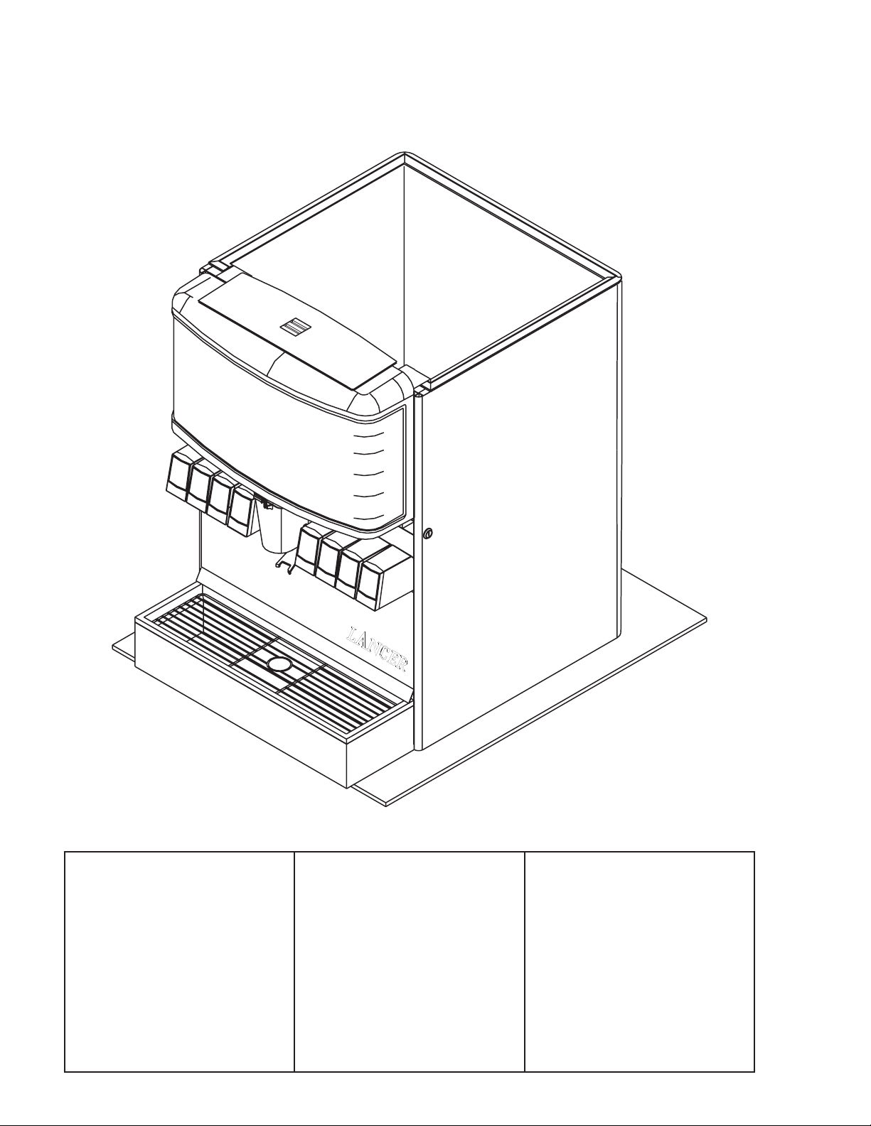
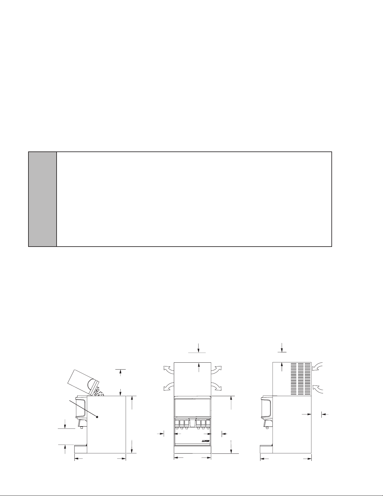
1.3 SELECTING COUNTER LOCATION (SEE FIGURE 1)
WARNING THIS APPLIANCE MUST BE EARTHED. THIS DISPENSER MUST BE ELECTRICALLY GROUNDED TO
AVOID DANGER TO THE OPERATOR. THE POWER CORD PROVIDED HAS A THREE PRONG GROUNDED PLUG. IF
A THREE HOLE GROUNDED ELECTRICAL OUTLET IS NOT AVAILABLE, USE AN APPROVED METHOD OF
INSURING A PROPER GROUND TO THE DISPENSER.
ADVERTENCIA ESTE APARATO DEBE CONECTARSE A TIERRA. ESTE DISPENSADOR DEBE TENER
CONEXIÓN A TIERRA PARA EVITAR PELIGRO PARA EL OPERADOR. EL CABLE SUMINISTRADO TIENE UN
ENCHUFE DE TIERRA DE TRES PUNTAS. SI UN AGUJERO TRES TOMACORRIENTE PUESTO A TIERRA NO ESTÁ
!
DISPONIBLE, UTILICE UN MÉTODO APROBADO DE ASEGURAR UNA TIERRA CORRESPONDIENTE EN LA
CUBETA.
AVERTISSEMENT CET APPAREIL DOIT ETRE MIS A LA TERRE. CE DISTRIBUTEUR DOIT ÊTRE MIS À LA TERRE
ÉLECTRIQUE POUR ÉVITER DANGER POUR L’OPÉRATEUR. LE CORDON D’ALIMENTATION FOURNIS A UN TROIS
BROCHES TERRE. SI UN TROIS TROUS TERRE ALIMENTATION ÉLECTRIQUE N’EST DISPONIBLE, UTILISER UNE
MÉTHODE APPROUVÉE D’ASSURER UN MOTIF VALABLE AU DISTRIBUTEUR.
A. Select a location close to a properly grounded electrical outlet, convenient to an open type
drain, access for soda, water, and syrup lines, and sufcient clearance for air circulation.
1. If at all possible, location should be away from direct sunlight or other heat sources.
2. Connecting lines may be run through access in back of the unit or extend down through a
counter cut out.
3. The counter must support the weight of the dispenser, ice, and possibly an ice maker. Total
weight may exceed 800 lbs (363.6 kg).
B. Unit may be installed directly on the countertop or on legs supplied with the unit. If installed
directly on the counter, the unit must be sealed to the countertop. If an ice maker is to be
mounted on top of dispenser, do not install dispenser on legs.
FIGURE 1.
ENSURE KEY SWITCH
IS ACCESSIBLE
9 3/4” (248 MM)
DISPENSE HEIGHT
SUFFICIENT CLEARANCE FOR
FILLING MANUALLY WITH ICE,
WHEN ICE MAKER NOT USED
36” (925 MM)
MINIMUM of 6" (152 mm)
clearance above ice maker
AIR
OUT
OUT
AIR
ecnaraelc )mm 251( "6
I C E
PUSH
OUT
AIR
AIR
OUT
ecnaraelc )mm 251( "6
34" (864 mm)
MINIMUM of 6" (152 mm)
clearance above ice maker
IN
AIR
AIR
IN
ecnaraelc llaw
MUMINIM of 6" (152 mm)
10
22" (559 mm)
30 1/2" (775 mm)
Page 11

1.3 SELECTING COUNTER LOCATION (CONTINUED)
NOTE: Water pipe connections and xtures directly connected to a potable water supply must all be
sized, installed, and maintained according to Federal, State, and Local laws. The water supply must
be protected by means of an air gap, a backow prevention device (located upstream of the CO2
injection system) or another approved method to comply with NSF standards. A backow
prevention device must comply with ASSE and local standards. It is the responsibility of the installer
to ensure compliance.
C. Location must insure sufcient clearance on sides, top and back of unit is provided for
ventilation and air circulation (see Figure 1).
D. Additionally, if an ice maker is not top mounted on the unit, sufcient clearance should be
provided [a minimum of 16 inches (40.6 cm) is recommended] to allow lling the unit with ice
from a ve (5) gallon (19 liter) container (see Figure 1).
1.4 INSTALLING THE DISPENSER
A. Remove Cup Rest, Drip Tray, Splash Plate, and Top Cover.
B. Remove Cover Plate at rear of unit if not a through the counter installation.
C. Connect soda and water supply lines to 3/8 inch barb ttings at the front of the unit. Check for
leaks. (If dispenser is to operate with all soda valves, connect water line into one of the soda
supply lines.)
D. Connect syrup supply lines to the 3/8 inch barb inlet ttings at the front of the unit. Check for
leaks.
E. Uncoil drain hose from Cold Plate drain and extend to an open type drain.
F. Install Drip Tray and extend hose to open type drain.
G. Both drain lines must be insulated with a closed cell insulation. Insulation must cover the entire
length of the drain hose, including ttings. The drain should be installed in such a manner that
water does not collect in sags or other low points, as condensation will form.
H. Install Cup Rest and Splash Plate.
I. Connect Power Cord to grounded electrical outlet.
J. Test Motor operation by pushing Ice Chute.
K. Clean and sanitize dispenser (see Section 2).
L. Fill unit approximately half full with ice. Push Chute and check for ice delivery.
M. Finish lling unit with ice.
N. Install Top Cover.
NOTE: Lancer does not recommend the use of shaved, ake, nugget, or pellet ice in dispensers not
properly equipped to do so.
O. Set brix ratio for beverage dispensing valves according to manufacturer’s instructions.
!
WARNING WHEN INSTALLING AN ICEMAKER ON AN IBD UNIT, A BIN THERMOSTAT OR OTHER MEANS
OF CONTROLLING THE ICE LEVEL MUST BE INSTALLED. FAILURE TO DO SO COULD RESULT IN DAMAGE TO
THE DISPENSING MECHANISM AND VOID THE WARRANTY. DURING THE AUTOMATIC AGITATION CYCLE AND/OR
WHILE DISPENSING ICE, THERE MUST BE ADEQUATE ROOM BETWEEN THE TOP OF THE ICE LEVEL AND THE
BOTTOM OF THE ICEMAKER SO THAT THE ICE CAN MOVE WITHOUT OBSTRUCTION. CONTACT YOUR
ICEMAKER SUPPLIER FOR INFORMATION ON PROPER BIN THERMOSTAT.
ADVERTENCIA AL INSTALAR UNA MÁQUINA DE HIELO EN UNA UNIDAD DE IBD, A BIN TERMOSTATO U OTROS
MEDIOS DE CONTROLAR EL NIVEL ICE DEBE ESTAR INSTALADO. NO HACERLO PUEDE CAUSAR
DAÑOS AL MECANISMO DISPENSING Y ANULAR LA GARANTÍA. DURANTE EL CICLO AUTOMÁTICO AGITACIÓN Y
/ O HIELO, MIENTRAS QUE LA DISPENSACIÓN, DEBE HABER ESPACIO SUFICIENTE ENTRE EL TOP DEL NIVEL
DE HIELO Y EL FONDO DE LA MÁQUINA DE HIELO PARA QUE EL ICE PUEDE MOVERSE SIN OBSTRUCCIÓN.
CONTACTO CON SU PROVEEDOR DE FABRICACIÓN DE HIELO PARA INFORMACIÓN SOBRE ADECUADO BIN
TERMOSTATO.
AVERTISSEMENT LORSQUE VOUS INSTALLEZ UNE MACHINE À GLAÇONS SUR UNE UNITÉ EIA, UN
THERMOSTAT DU BAC OU AUTRES MOYENS DE CONTRÔLER LE NIVEAU DE LA CIE DOIT ÊTRE INSTALLÉ.
PANNE DE LE FAIRE POURRAIT PROVOQUER DES DOMMAGES AU MÉCANISME DE DISTRIBUTION ET ANNULE
LA GARANTIE. PENDANT LE CYCLE AUTOMATIQUE AGITATION ET / OU TOUT DISTRIBUTION DE GLACE,
DOIVENT TROUVER PLACE SUFFISANTE ENTRE LE SOMMET DE L’ÉCHELLE DE L’ICE ET LE BAS DE LA
MACHINE À GLAÇONS POUR QUE LA GLACE PEUT SE DÉPLACER SANS ENTRAVE. CONTACTEZ VOTRE
FOURNISSEUR DE ICEMAKER INFORMATIONS SUR UNE BONNE THERMOSTAT DU BAC.
11
Page 12

1.5 ADJUSTING THE ICE FLOW REGULATOR
Turn Screw to Adjust
Adjustment
To Ice
ICE
CUT AWAY VIEW
Access Slot in
If necessary, bend
Wheel
Clockwise to Close
Counter Clockwise to Open
Plastic Wheel Shroud
slightly forward for
easier installation.
for adjustment
Use the access slot
Shroud
Dispensing Chute
SIDE
(230 VOLT UNITS ONLY) (SEE FIGURE 2)
The Regulator Door Assembly (PN 82-2904) can
Ice Flow Regulator is NOT necessary for the
dispensing of ice. This IBD unit will dispense ice
unrestricted.
A. Remove Bin Lids.
B. Adjust Ice Regulator to desired position by
turning the nut screw clockwise to close, or
counter clockwise to open, with the use of a nut
driver or a socket wrench (see Figure 2).
NOTE: Total adjustment: 1/2 inch.
C. Reinstall bin lids.
2. CLEANING AND SANITIZING INSTRUCTIONS
2.1 GENERAL INFORMATION
A. Lancer equipment (new or reconditioned) is shipped from the factory cleaned and sanitized in
accordance with NSF guidelines. This equipment must be cleaned and sanitized after
installation is complete, and the operator of the equipment must provide continuous
maintenance as required by this manual and/or state and local health department guidelines to
ensure proper operation and sanitation requirements are maintained.
NOTE: The cleaning and sanitizing procedures provided herein pertain to the Lancer equipment
identied by this manual. If other equipment is being cleaned, follow the guidelines established
for that equipment.
B. Cleaning and sanitizing should be accomplished only by trained personnel. Sanitary gloves are
to be used during cleaning and sanitizing operations. Applicable safety precautions must be
observed. Instruction warnings on the product being used must be followed.
C. Water lines are not to be disconnected during the cleaning and sanitizing of syrup lines to avoid
contamination.
D. Do NOT use strong bleaches or detergents. They tend to discolor and/or corrode various
materials.
E. Do NOT use metal scrapers, sharp objects, steel wool, scouring pads, abrasives, solvents, etc.,
on the dispenser.
F. Do NOT use hot water above 140°F (60°C). This may damage certain materials.
2.2 REQUIRED CLEANING EQUIPMENT
A. Cleansers (for example, Ivory Liquid, Calgon, etc.) mixed with clean, potable water at a
temperature of 90 to 110 degrees Fahrenheit should be used to clean equipment. The mixture
ratio, using Ivory Liquid, is one (1) ounce of cleanser to two (2) gallons of water. A minimum of
ve (5) gallons of cleaning mixture should be prepared. Any equivalent cleanser may be used
as long as it provides a caustic based, non-perfumed, easily rinsed mixture containing at least
two (2) percent sodium hydroxide (NaOH). Rinsing must be thorough and use clean, potable
water which is also at a temperature of 90° to 110°F.
NOTE: Extended lengths of product lines may require that an additional volume of cleaning solution
B. Sanitizing solutions should be prepared in accordance with the manufacturer’s written
recommendations and safety guidelines. The solution must provide 200 parts per million (PPM)
available chlorine. A minimum of ve (5) gallons of sanitizing solution should be prepared. Any
sanitizing solution may be used as long as it is prepared in accordance with the manufacturer’s
written recommendations and safety guidelines, and provides 200 parts per million (PPM)
available chlorine. Sanitizing solution is to be purged from line(s) and equipment by ushing
with product only until there is no after taste. Do not rinse with water.
regulate the dispensed ice ow. Installation of an
be prepared.
FIGURE 2.
12
Page 13

2.2 REQUIRED CLEANING EQUIPMENT (CONTINUED)
NOTE: Please note that a fresh water rinse cannot follow sanitization of equipment. Purge only with
the end use product until there is no after taste in the product. This is an NSF requirement.
Extended lengths of product lines may require that an additional volume of sanitizing solution
be prepared.
C. Other:
1. Clean cloth towels.
2. Bucket.
3. Small brush (PN 22-0017) - included with installation kit.
4. Extra nozzle.
5. Sanitary gloves.
2.3 DAILY CLEANING
Using a mild detergent solution, clean Top Cover and all exterior stainless steel surfaces. Clean
exterior of dispensing valves and ice chute. Remove Cup Rest. Clean Drip Tray and Cup Rest, and
replace Cup Rest. Wipe clean all splash areas using a damp cloth soaked in cleaning solution.
Clean beverage valves as specied by the valve manufacturer.
2.4 ICE BIN CLEANING - START UP AND MONTHLY
A. Disconnect Dispenser from power source.
B. Remove Top Cover.
C. Remove Agitator Pin from Agitator Shaft. Slide Agitator Shaft rearward out of Motor Shaft and
pull out of rear Bearing to remove.
D. Remove Dispensing Wheel from Motor Shaft by sliding rearward.
E. Remove Dispensing Wheel Shroud.
F. Remove Splash Plate Assembly by lifting it up and out from the dispenser face.
G. Using cleaning solution, described in Section 2.2, and a clean cloth or soft brush, clean all
removable parts, sides of Ice Bin, Ice Chute, and surface of aluminum casting.
H. Repeat Step G for all exterior surfaces of the dispenser.
I. Using hot water, thoroughly rinse away the cleaning solution.
J. Wearing sanitary gloves, soak a clean cloth towel in sanitizing solution, described in Section 2.2,
and wash all surfaces of removable parts, sides of Ice Bin, Ice Chute, and surface of aluminum
casting.
K. Repeat Step J for all metal and plastic surfaces (but not labels) of the dispenser exterior.
L. Wearing sanitary gloves, reassemble all removable parts.
M. Fill Unit with ice and replace Top Cover.
NOTE: Lancer does not recommend the use of shaved, ake, nugget, or pellet ice in dispensers not
properly equipped to do so.
N. Reconnect Dispenser to power source.
2.5 CLEANING AND SANITIZING BEVERAGE COMPONENTS - FIGAL SYSTEMS
NOTE: Extended lengths of product lines may require more time than stated below to ush and
rinse lines.
A. Disconnect syrup lines from syrup containers (for example, quick disconnects, gal containers,
etc.).
B. Connect hose half of syrup line to a syrup tank lled with clean, potable, room temperature
water. Connect CO2 supply hose to tank and pressurize.
C. Activate valve until water is dispensed. Flush and rinse line and ttings for a minimum of 60
seconds to remove all traces of residual product.
13
Page 14

2.5 CLEANING AND SANITIZING BEVERAGE COMPONENTS - FIGAL SYSTEMS (CONTINUED)
WARNING TO AVOID POSSIBLE PERSONAL INJURY OR PROPERTY DAMAGE, DO NOT ATTEMPT TO
REMOVE SYRUP TANK COVER UNTIL CO2 HAS BEEN RELEASED FROM TANK.
ADVERTENCIA PARA EVITAR POSIBLES LESIONES PERSONALES O DAÑOS MATERIALES, NO TRATE DE
RETIRAR LA TAPA DEL TANQUE DE SOROPE HASTA QUE SE HAYA LIBERADO LA PRESIÓN DEL CO2 DEL
TANQUE.
!
AVERTISSEMENT POUR ÉVITER DES BLESSURES OU DES DOMMAGES MATÉRIELS POSSIBLES, N’ESSAYEZ
PAS DE RETIRER LE COUVERCLE DU RÉSERVOIR DE SIROP, JUSQU’A CE QUE DE LA PRESSION DE CO2 AIT
ÉTÉ LIBÉRÉE DU RESERVOIR.
D. Disconnect CO2 supply hose from the water lled syrup tank.
E. Following the instructions as described in Section 3.1 above, mix appropriate amount of cleaning
solution. Fill a tank with this solution. Connect hose half of syrup line to the tank. Connect CO2
supply hose to tank and pressurize.
F. Activate valve and draw cleaning solution through lines for a minimum of 60 seconds. This will
ensure line is ushed and lled with cleaning solution. Allow line to stand for at least 30 minutes.
G. Disconnect CO2 supply hose from the tank.
H. Connect hose half of syrup line to a tank lled with clean, potable, water at a temperature of 90°
to 110°F. Connect CO2 supply hose to tank and pressurize.
I. Activate valve to ush and rinse line and ttings for a minimum of 60 seconds to remove all
traces of cleaning solution. Taste dispensed product to ensure there is no off-taste. If off-taste is
found, additional ushing of syrup system may be required.
J. Disconnect CO2 supply hose from the tank.
K. Reconnect Dispenser to power source.
L. Following the instructions as described in 3.1 above, mix appropriate amount of sanitizing
solution.Fill a tank with this solution. Connect hose half of syrup line to the tank. Connect CO2
supply hose to tank and pressurize.
M. Activate valve and draw sanitizing solution through line for a minimum of 60 seconds. This will
ensure line is ushed and lled with sanitizing solution. Allow line to stand for at least 30
minutes.
N. Disconnect CO2 supply hose from the tank.
O. Reconnect syrup lines to syrup containers (for example, quick disconnects, gal containers, etc.)
and ready unit for operation.
P. Draw drinks to rell the lines and ush the sanitizing solution from the dispenser.
NOTE: Please note that a fresh water rinse cannot follow sanitization of equipment. Purge only with
the end use product until there is no after taste in the product.
Q. Test dispenser in normal manner for proper operation. Taste dispensed product to ensure off-
taste is not present. If off-taste is found, additional ushing of syrup system may be required.
R. Repeat cleaning, rinsing, and sanitizing procedures for each valve and each circuit.
2.6 CLEANING AND SANITIZING BEVERAGE COMPONENTS - BAG-IN-BOX SYSTEMS
NOTE: Extended lengths of product lines may require more time for ushing and rinsing lines than
described below.
A. Disconnect the syrup quick disconnect coupling from the syrup packages and connect the
coupling to a bag valve removed from an empty Bag-in-Box (BIB) package.
B. Place the syrup inlet line in a clean container lled with clean, potable, room temperature water.
C. Activate valve until water is dispensed. Flush and rinse line and ttings for a minimum of 60
seconds to remove all traces of residual product.
D. Following the instructions as described in 3.1 above, mix appropriate amount of cleaning
solution in a clean container. Place syrup inlet line in container lled with cleaning solution.
E. Activate valve and draw cleaning solution through lines for a minimum of 60 seconds. This will
ensure line is ushed and lled with cleaning solution. Allow line to stand for at least 30 minutes.
F. Place syrup inlet line in a clean container lled with clean, potable, water at a temperature of 90°
to 110°F.
G. Activate valve to ush and rinse line and ttings for a minimum of 60 seconds to remove all
traces of cleaning solution.
14
Page 15

2.6 CLEANING AND SANITIZING BEVERAGE COMPONENTS - BAG-IN-BOX SYSTEMS
(CONTINUED)
H. Following the instructions as described in 3.1 above, mix appropriate amount of sanitizing
solution in a clean container. Place syrup inlet line in container lled with sanitizing solution.
Refer to Section 3.3 CAUTION.
I. Activate valve and draw sanitizing solution through line for a minimum of 60 seconds. This will
ensure line is ushed and lled with sanitizing solution. Allow line to stand for at least 30
minutes.
J. Remove bag valve from quick disconnect coupling and reconnect syrup inlet line to syrup
package. Ready unit for operation.
K. Draw drinks to rell lines and to ush the chlorine sanitizing solution from the dispenser.
NOTE: Please note that a fresh water rinse cannot follow sanitization of equipment. Purge only with
the end use product until there is no after taste in the product. This is an NSF requirement.
L. Test dispenser in normal manner for proper operation. Taste dispensed product to ensure
off-taste is not present. If off-taste is found, additional ushing of syrup system may be required.
M. Repeat cleaning, rinsing, and sanitizing procedures for each valve and each circuit.
15
Page 16

3. TROUBLESHOOTING
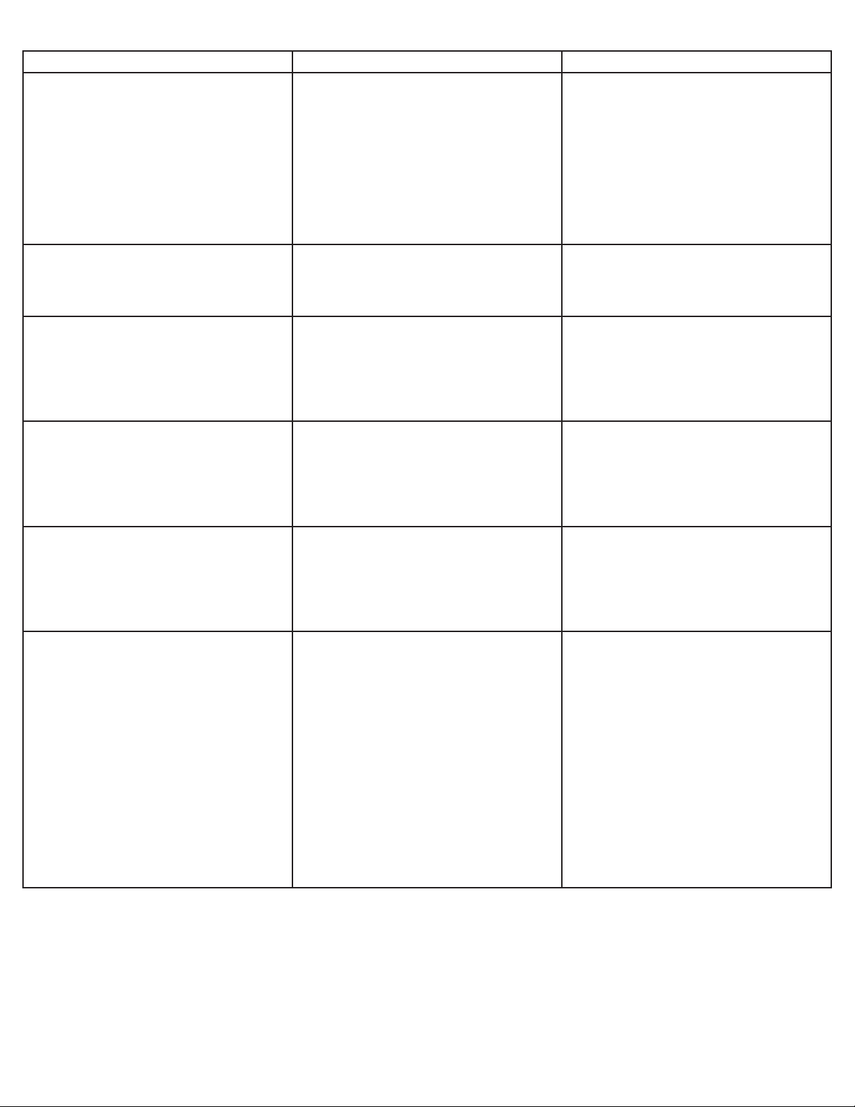
ISSUE CAUSE SOLUTION
3.1 No product when switch is activated
(switch panel is not lit).
A. Malfunctioning switch assembly.
B. No power to dispenser.
A. Replace switch assembly.
B. Check internal breaker and incoming
power.
C. Malfunctioning power supply.
D. Malfunctioning PCB board.
3.2 No product when switch is activated
(switch panel is lit).
3.3 Push chute; no response. A. Dispenser not connected to power
A. Keyswitch is off or keyswitch harness
is disconnected.
B. Malfunctioning switch assembly.
C. Malfunctioning LEV module.
source.
B. Hall-effect sensor defective.
C. Wiring harness not plugged in.
D. PC board defective.
E. Malfunctioning power supply.
F. Magnet not in ice chute shell.
C. Check voltage to power supply. Check
fuses.
D. Replace PCB board.
A. Turn keyswitch on and/or reconnect
keyswitch harness.
B. Replace switch assembly.
C. Replace module.
A. Connect dispenser to power source.
B. Replace ice chute base.
C. Plug in wiring harness.
D. Replace PC board.
E. Check voltage to power supply. Check
fuses.
F. Install magnet in ice chute shell.
3.4 Push chute, ice door opens but motor
does not run.
3.5 Push chute, motor runs but ice door
does not open.
3.6 Push chute, ice door opens, motor
runs, but ice does not dispense, or ice is
of poor quality.
A. Wiring harness not plugged in.
B. PC board defective.
C. Motor defective.
A. Solenoid not connected to PC board.
B. Solenoid defective.
C. PC board defective.
A. Dispenser is out of ice.
B. Agitator pin is missing or damaged.
C. Poor ice quality.
D. Key not installed on auger shaft.
E. Auger trough empty.
A. Plug in wiring harness.
B. Replace PC board.
C. Replace motor.
A. Connect solenoid to PC board.
B. Replace solenoid.
C. Replace PC board.
A. Fill dispenser with ice.
B. Replace agitator pin.
C. Service ice machine.
D.Install key on auger shaft.
E. Change agitation settings.
16
Page 17

ISSUE CAUSE SOLUTION
3.7 Water in ice bin. A. Coldplate drain is obstructed. A. Remove splash plate and drip tray to
obtain access to drain tubes and clear
accordingly.
3.8 Water leakage around nozzle. A. Damaged or improperly installed o-ring
on nozzle.
3.9 Miscellaneous leakage. A. Gap between parts.
B. Damaged or improperly installed
o-rings.
3.10 Noisy/cavitating carbonator pump. A. Insufcient incoming water
supply pressure.
3.11 Insufcient soda ow (carbonated
drinks).
3.12 Insufcient water ow (plain water
drinks).
A. Insufcient CO2 supply pressure.
B. Shutoff on mounting block is not fully
open.
C. Foreign debris in soda ow control.
A. Insufcient incoming supply pressure.
A. If damaged, replace. If improperly
installed, adjust.
A. Tighten appropriate retaining screws.
B. Replace or adjust appropriate o-rings.
A. Verify incoming supply water
pressure to carbonator pump is min. of
25 PSI, max. of 50 PSI.
A. Verify incoming CO2 pressure is
between 70-75 PSI.
B. Open shutoff fully.
C. Remove soda ow control from valve
and clean out any foreign material to
ensure smooth spool movement.
A. Verify incoming supply water pressure
to plain water inlet is a minimum of
75 PSI, max. of 125 PSI.
B. Shutoff on mounting block not fully
open.
C. Foreign debris in water ow control.
D. Water ltration problem.
3.13 Erratic ratio. A. Incoming water and/or syrup supply
not at minimum owing pressure.
B. Foreign debris in water and/or syrup
ow control.
C. CO2 regulator malfunction.
B. Open shutoff fully.
C. Remove water ow control from valve
and clean out any foreign material to
ensure smooth spool movement.
D. Service water system as required.
A. Check pressure and adjust.
B. Remove ow control from suspected
valve and clean out any foreign
material to ensure smooth spool
movement.
C. Repair or replace CO2 regulator.
17
Page 18

ISSUE CAUSE SOLUTION
3.14 Insufcient syrup ow. A. Insufcient CO2 pressure to BIB
pumps.
A. Adjust CO2 pressure to BIB pumps to
80 PSI (min. 70 PSI). Do not exceed
manufacturer’s recommendations.
B. Shutoff on mounting block not fully
open.
C. Foreign debris in syrup ow control.
D. Defective BIB pump.
3.15 Valve will not shut off. A. Debris in solenoid seat.
B. Solenoid plunger sticking.
3.16 Water continually leaking at
connections.
3.17 Water only dispensed, no syrup.
Or syrup only dispensed, no water.
A. Loose water connections.
B. Flare seal washer leaks.
A. Syrup BIB empty.
B. Water or syrup shutoff on
mounting block not fully open.
C. Improper or inadequate water
or syrup supply.
B. Open shutoff fully.
C. Remove syrup ow control from valve
and clean out any foreign material to
ensure smooth spool movement.
D. Replace pump.
A. Activate valve a few times to free
debris. Remove the solenoid coil and
plunger. Clean out any foreign material.
B. Replace solenoid coil.
A. Tighten water connections.
B. Replace are seal washer.
A. Replace syrup BIB as required.
B. Open shutoff completely.
C. Remove valve from mounting block &
open shutoffs slightly. Check water &
syrup supply. If no supply, check unit for
other problems. Ensure BIB connection
is engaged.
D. CO2 pressure to syrup pump
too low.
E. Stalled or inoperative BIB
pump.
F. Kinked line.
G. CO2 regulator malfunction.
H. Defective LFCV module.
D. Check the CO2 pressure to the pump
to ensure it is between 70-80 PSI.
E. Check CO2 pressure and/or replace
pump.
F. Remove kink or replace line.
G. Repair or replace CO2 regulator as
required.
H. Replace module.
18
Page 19

ISSUE CAUSE SOLUTION
3.18 Syrup only dispensed. No water, but
CO2 gas dispensed with syrup.
A. Improper water ow to dispenser.
B. Carbonator pump motor has timed out
(display message on the LCD screen).
A. Check for water ow to dispenser.
B. Reset by turning the unit OFF, then ON
by using the circuit breaker on the
power supply or momentarily unplugging
unit.
C. Liquid level probe not connected
properly to PCB.
D. Defective PCB assembly.
E. Defective liquid level probe.
F. Weak or defective carbonator pump.
3.19 Excessive foaming. A. No ice in bin.
B. Incoming water or syrup temperature
too high.
C. CO2 pressure too high.
D. Water ow rate too high.
E. Nozzle and diffuser not clean.
F. Air in BIB lines.
3.20 Circuit breaker tripping. A. Valve wire harness shorted to itself
or faucet plate.
C. Check connections of liquid level
probe to PCB assembly.
D. Replace PCB assembly.
E. Replace liquid level probe.
F. Replace pump.
A. Fill bin with ice and allow coldplate
to re-stabilize.
B. Correct prior to dispenser.
C. Adjust CO2 pressure downward, but
not less than 70 PSI.
D. Re-adjust and reset ratio.
E. Remove and clean.
F. Bleed air from BIB lines.
A. Detect short by disconnecting valve
harnesses from switch panel (4 25-pin
harnesses and 4 9-pin harnesses).
Restore power. If breaker does not trip,
nd and replace shorted harness. If
breaker trips, re-install the 8 harnesses,
and proceed to step B.
B. Controller PCB is bad.
C. Secondary wire harness has a short.
D. Power supply is bad.
19
B. Detect by disconnecting the white
5-pin harness from the controller PCB.
Restore power. If breaker does not trip,
replace controller PCB. If breaker trips,
re-install the white 5-in harness and
proceed to step C.
C. Locate short from a motor or solenoid
harness and replace.
D. Detect short by disconnecting all
harnesses connected to power supply.
Restore power. If breaker still trips,
replace power supply.
Page 20
ISSUE CAUSE SOLUTION
3.21 BIB pump does not operate when
dispensing valve is opened.
A. Out of CO2, CO2 not turned on, or low
CO2 pressure.
A. Replace CO2 supply, turn on CO2
supply, or adjust CO2 pressure to
70-80 PSI.
B. Out of syrup.
C. BIB connector not tight.
D. Kinks in syrup or gas lines.
3.22 BIB pump operating, but no ow. A. Leak in syrup inlet or outlet line.
B. Defective BIB pump.
3.23 BIB pump continues to operate
when bag is empty.
3.24 BIB pump fails to restart after bag
replacement.
3.25 BIB pump fails to stop when
dispensing valve is closed.
A. Leak in suction line.
B. Leaking o-ring on pump inlet tting.
C. Defective syrup BIB pump.
A. BIB connector not on tightly.
B. BIB connector is stopped up.
C. Kinks in syrup line.
A. Leak in discharge line or ttings.
B. Empty BIB.
B. Replace syrup supply.
C. Fasten connector tightly.
D. Straighten or replace lines.
A. Replace line.
B. Replace BIB pump.
A. Replace line.
B. Replace o-ring
C. Replace defective pump.
A. Tighten BIB connector.
B. Clean out or replace BIB connector.
C. Straighten or replace line.
A. Repair or replace discharge line.
B. Replace BIB.
C. Air leak on inlet line or bag connector.
3.26 Low or no carbonation. A. Low or no CO2.
B. Low water pressure.
C. Worn or defective carbonator pump.
D. Backow preventer not allowing water
to ow.
E. Probe malfunctioning.
F. PCB malfunctioning.
C. Repair or replace.
A. Check CO2 supply. Adjust CO2
pressure to 70 PSI.
B. Need water booster kit.
C. Replace carbonator pump.
D. Replace backow preventer, noting
the ow direction arrow from pump to
coldplate.
E. Replace probe.
F. Replace PCB.
20
Page 21

4. LIGHT EMITTING DIODES (LEDS)
4.1 LED D3
This light is on when the ice dispense switch is activated. If the chute is depressed and the light
does not turn on, check to see if the wire harness is connected or if the dispense switch is
defective.
4.2 LED D4
This light is used on units with lid interlock switches. On the 4500 series ice-beverage dispenser,
this light should always be lit. If it is not, check the Lid Interlock Jumper (black wire with 4 pin white
connector).
4.3 LED D5
This light is on when +5VDC is present at the circuit board. It should be lit whenever the unit is
connected to a power source. If the light is off, check to see if the internal circuit breaker on the
transformer has tripped. If it has tripped, it can be reset by depressing the switch on the top of the
transformer.
4.4 LED D6
This light is on when +32VDC is present at the circuit board. It should be lit whenever the unit is
connected to a power source. If the light is off, check to see if the internal circuit breaker on the
transformer has tripped. If it has tripped, it can be reset by depressing the switch on the top of the
transformer.
4.5 LED D7
This light ashes when there is no ice between the sensors in the ice bin. If the bin is empty and the
light is not ashing, check all wiring harnesses.
4.6 LED D8
This light is on when the solenoid is activated. When the chute is depressed, this light should turn
on. If it does not, check to see if the solenoid leads are connected to the PC board or damaged,
check continuity of solenoid. Replace if defective.
4.7 LED D9
This light is on when the motor is activated. When the chute is depressed, this light should turn on.
If it does not, check to see if the motor harness is connected to the PC board or damaged, check
continuity of motor harness and motor. Replace if defective.
5. AUTOMATIC AGITATION AND LOW ICE ALARM CONTROL
WARNING THIS UNIT IS EQUIPPED WITH AUTOMATIC AGITATION. IT MAY ACTIVATE UNEXPECTEDLY. DO
NOT PLACE HANDS, OR FOREIGN OBJECTS IN THE ICE STORAGE COMPARTMENT. WHEN UNIT IS BEING
SERVICED, CLEANED, OR SANITIZED, UNPLUG DISPENSER FROM THE POWER SOURCE.
ADVERTENCIA ESTA UNIDAD ESTÁ EQUIPADA CON AUTOMÁTICO AGITACIÓN. PUEDE ACTIVAR
INESPERADAMENTE. NO INTRODUZCA LAS MANOS, NI OTROS OBJETOS EXTRAÑOS EN EL COMPARTIMIENTO
DE ALMACENAMIENTO DE HIELO. CUANDO LA UNIDAD SE ESTÁ ATENDIENDO, LIMPIADOS O DESINFECTADOS
!
Each Series 4500 ice beverage dispenser is equipped with automatic agitation for the ice bin. The unit is
shipped with timing set at two (2) seconds ON every 60 minutes. Referring to the tables on the wiring
diagram included in this manual (also afxed to the electrical box cover), the automatic agitation
timing can be changed as follows. A set of DIP switches is provided to control the timing and low ice
control.
NOTE: Dispensers using pellet ice must have the automatic agitation settings adjusted to four (4)
seconds ON every 150 minutes. See Section 6.11.
DISPENSADOR DESENCHUFE DE LA FUENTE DE ALIMENTACIÓN.
AVERTISSEMENT CET APPAREIL EST ÉQUIPÉ AUTOMATIQUE AGITATION. ELLE PEUT ACTIVER UNE FAÇON
INATTENDUE. NE PAS METTRE LES MAINS OU DES OBJETS DANS LE COMPARTIMENT DE STOCKAGE DE
GLACE. AVEC L’APPAREIL EST RÉPARÉ, NETTOYÉES OU ASEPTISÉ, DISTRIBUTEUR DÉBRANCHEZ LA SOURCE
D’ALIMENTATION.
21
Page 22

5. AUTOMATIC AGITATION AND LOW ICE ALARM CONTROL (CONTINUED)
5.1 DIP#1
This switch controls the low ice indicator light. With the switch in the ON position, the light operates
when a low ice condition exists. In the OFF position, the light is turned off. The unit is shipped with
the light switch in the ON position.
5.2 DIP#2
This switch controls the low ice audible alarm. With the switch in the ON position, the alarm
operates when a low ice condition exists. In the OFF position, the alarm is turned off. The unit is
shipped with the alarm switch in the OFF position.
5.3 DIP#3 & #4
These switches control the ON time for automatic agitation. By referring to the table and setting the
switches as shown, ON times from one (1) second to four (4) seconds [in one (1) second
increments] can be obtained. EXAMPLE: For three (3) seconds ON time, switch 3 should be in the
ON position, and switch 4 should be in the OFF position. The unit is shipped with two (2) seconds
ON time.
5.4 DIP#5 through #8
A. These switches control the OFF time for automatic agitation. By referring to the table and
setting the switches as shown, OFF times from 10 minutes to 150 minutes (in 10 minute
increments) can be obtained. EXAMPLE: For 40 minute OFF time, switch 5 should be in the
OFF position, switch 6 should be in the ON position, switch 7 should be in the OFF position,
and switch 8 should be in the OFF position. The unit is shipped with 60 minute OFF time.
B. To turn the agitation completely off, set switches 5 through 8 all OFF.
22
Page 23

NOTES
23
Page 24

6. ILLUSTRATIONS, PARTS LISTINGS, AND WIRING DIAGRAMS, IBD25
6.1 DECALS AND LABELS, IBD25
D
ELEC
A
N
HAZ
TRI
G
U
ARDO
N
CAL
I
T
E
M
SHO
A
D
R
Y
US M
IS
A
C
S
C
O
E
T
CK
R
N
IV
V
O
N
A
IC
E
T
VI
HAZ
C
E
IN
T
NG P
U
G
P
N
O
ARD
O
E
W
R
X
ART
P
E
C
E
R
L
C
E
B
T
A
S
E
E
N
F
D
I
O
N
L
Y
R
G
E
U
N
I
T
1
.
2
10
9
3
4
8
5
6
7
24
Page 25

6.1 DECALS AND LABELS, IBD25 (CONTINUED)
Item Part No. Description
- 85-4528H-100 IBD25H, Series 4500, 115V/60Hz, 8 LEV®
- 85-4538H-100 IBD25H, Series 4500, 230V,/50-60Hz, 8 LEV®
1 06-1139 Label, Warning, Lid, IBD
2 06-2117/01 Panel, Graphic, IBD25, Round
3 06-1184/01 Label, Cleaning, Merchandiser
R 4 06-1182/04 Label, Wiring Diagram, 115V, IBD (See Section 6.6)
R - 06-1521/02 Label, Wiring Diagram, 230V, IBD (See Section 6.7)
R 5 06-2226 Label, Plumbing Diagram, IBD25 (See Section 6.2)
6 06-1522 Label, Low Ice, IBD
7 06-1207 Label, Cold Plate Cleaning, IBD
8 06-2058/01 Decal, Wrapper, Side, IBD, Round
9 06-1183 Label, Cleaning, Hopper, IBD
10 06-2118/01 Decal, Wrapper, Back, IBD25, Round
- 12-0193 Ice Out Indicator
- 27-0068, Lens, Clear, Marquee
- 27-0071, Diffuser, Marquee
R in margin indicates change or revision
25
Page 26

6.2 FINAL ASSEMBLY, POST-MIX IBD AND ICE DISPENSER, IBD25
6
11
10
NOTE:
TO ADJUST ICE FLOW
REGULATOR, SEE SECTION 1.5
(230 VOLT ONLY)
2
4
3
7
1
5
8
9
9
1
14
12
13
15
26
Page 27

6.2 FINAL ASSEMBLY, POST-MIX IBD AND ICE DISPENSER, IBD25 (CONTINUED)
Item Part No. Description
- 85-4528H IBD25H, Series 4500, 115V/60Hz, 8 Valve
- 85-4538H IBD25H, Series 4500, 230V/50-60Hz, 8 Valve
R 1 05-1658/01 Wheel Shroud Assy, IBD25, Mod (115V)
R - 82-2705 Wheel Shroud Assy, IBD25, Mod (230V Only)
R 2 03-0368 Retainer, RUE-14-S
R 3 23-1373 Agitator Assy, HEX, IBD (115V)
R - 23-1355 Agitator Assy, IBD, (230V Only)
R 4 10-0762 Pin, Agitator, IBD, Single Retainer
R 5 82-3556 Dispensing Wheel Assy, HEX, IBD (115V)
R - 82-3413 Dispensing Wheel Assy, IBD (230V Only)
6 05-1659 Lid, Back, IBD25, Round
7 05-1476 Lid, Front, IBD, Round
8 23-1038/01 Drain, Spider, IBD
9 03-0300 Wire Clip, Adhesive
10 82-2706 Merchandiser Assy, IBD25
11 03-0049 Clip, Cord
12 12-0146/01 Lamp, 18 Inch, 15W, T8
13 82-2707-SP Drip Tray Assy, IBD, 25 Inch Wide (Before December 30, 2003)
-- 82-3186-SP Drip Tray Assy, IBD, 25 Inch Wide (After December 30, 2003)
14 30-7517/01 Plate, Splash, IBD, 25 Inch Wide (Before December 30, 2003)
-- 30-8625 Plate, Splash, IBD, 25 Inch Wide (After December 30, 2003)
15 04-0559 Cap, Protective, Vinyl, VC-375-8
R in margin indicates change or revision
27
Page 28

6.3 FAUCET PLATE AND ICE CHUTE SUB-ASSEMBLY, POST-MIX, IBD25
9
8
10
7
5
3
4
20
6
2
1
TO TRANSFORMER
TIE WRAP
WHITE
BLACK
TIE WRAP
BLACK
TO KEYSWITCH
BLACK
TIE WRAP
11
8
14
13
12
28
Page 29

6.3 FAUCET PLATE AND ICE CHUTE SUB-ASSEMBLY, POST-MIX, IBD25 (CONTINUED)
Item Part No. Description
- 85-4528H IBD25H, Series 4500,
115V/60Hz, 8 Valve
- 85-4538H IBD25H, Series 4500,
230V/50-60Hz, 8 Valve
1 04-0308 Screw, 10 - 32 X 0.438
2 82-2703 Faucet Plate Assy, IBD25
R 3 02-0005 O-Ring, 2-010
R 4 06-0877 Label, Ground
R 5 04-0553 Screw, 10 - 24 X 1.75, LG
R 6 82-3538 Chute Assy, Printed, Small
Dispenser, IBD
R 7 05-0928/01 Trap Door, IBD
R 8 04-0504 Screw, 8 - 18 x 0.375, PHD
R 9 82-1566/01 Solenoid Assy
R A 03-0086 Ring, Retaining (5304-18)
R B 04-0328 Washer, Rubber
R C 04-0327 Washer, Flat
R D 12-0195 Solenoid, D-90
R E 30-5165 Bracket, Solenoid
R F 23-1380 Plunger Assy
R G 10-0496 Pin, Solenoid Assy
R H 03-0110 Spring, Solenoid
R I 03-0111 Ring, Retaining (5133-62)
R J 10-0353 Linkage, Door, IBD
R K 04-0320 Screw, 8 - 32 x. 0.187, PHD
Item Part No. Description
R 10 82-2704 Trim Assy, IBD25, Round
11 30-5876/01 Cover, Electrical Box, IBD
R 12 30-6145 Lock, Drip Tray, IBD
R 13 10-0364 Spacer, Drip Tray Lock, IBD
R 14 04-0529 Screw, 8 - 32 x 0.750, PH
R 15 10-0732 Shaft, ice Chute Door
R 16 05-0359 Bushing, Shaft
R 17 03-0113 Ring, Retaining (5144-12)
R 18 05-0546 Lever, Door
R 19 03-0205 Ring, Retaining (5304-25)
R 20 12-0244 Ice Door Switch
R in margin indicates change or revision
K
A
E
B
C
D
F
G
H
I
9
18
J
17
15
16
19
29
7
Page 30

6.4 ELECTRICAL BOX AND GEAR MOTOR SUB-ASSEMBLY, POST-MIX, IBD25
20
12
29
28
27
12
9
26
12
26
25
1
12
12
14
24
15
12
23
16
12
19
24
23
22
20
21
20
2
3
4
6
5
7
8
9
10
14
17
12
16
18
15
10
11
12
12
13
12
30
Page 31

6.4 ELECTRICAL BOX AND GEAR MOTOR SUB-ASSEMBLY, POST-MIX, IBD25 (CONTINUED)
Item Part No. Description
- 85-4528H IBD25H, Series 4500, 115V/60Hz, 8 Valve
- 85-4538H IBD25H, Series 4500, 230V/50-60Hz, 8 Valve
1 30-7153 Wrapper Assy, IBD25, Round (Before December 30, 2003)
-- 30-8628 Wrapper Assy, IBD25, Round (After December 30, 2003)
2 82-2701H Tank Assy, Foamed, IBD25
R 3 02-0155 O-Ring, 2-015
4 05-1858 Body, Emitter, Sensor, Plug
5 05-1859 Body, Detector, Sensor, Plug
6 52-2352 Emitter Assy, Sensor
7 52-2353 Detector Assy, Sensor
8 02-0406 Seal, Shaft, Motor, IBD
9 06-2488 Label, Ice Link Tag, IBD
10 52-2450 Harness Assy, Detector, IBD
11 52-2122 Ballast Assy, Long Lead, 230V, IBD
12 04-0504 Screw, 8 - 18 x 0.375
13 30-6153 Bracket, Left, Light, IBD
14 04-0237 Screw, 8 - 32 x 0.250
15 52-1584 Harness Assy, Light, Black
16 52-1583 Harness Assy, Light, White
17 11-0295 Socket, 660W/600V MAX
18 30-6152 Bracket, Right, Light, IBD
R 19* 82-1529/02 Electrical Box Assy, IBD, 115V*
R -** 82-2017/02 Electrical Box Assy, IBD, 230V**
R - 52-1527 Power Cord Assy, 115V
R - 52-2006 Power Cord Assy, 230V
20 04-0069 Screw, 10 - 16 X 0.500
21 30-6147 Cover, Motor, IBD
R 22 82-3688 Drive Assy, Motor, HEX, IBD, 115V
- 82-2018 Drive Assy, Motor, IBD, 230V
23 04-0203 Screw, 3/8 - 16 X 1.00, FHD
24 07-0211 Washer, Shipping Base
25 90-0985 Shipping Board, IBD, 25 Inch Wide
26 52-2449 Harness Assy, Emitter, IBD
27 06-1580 Label, Patent
R 28*** 12-0097 Switch, Key Lock***
29 30-7113 Cover, Cutout, Wrapper, IBD
R - 05-1555 Rear Bearing (Not Shown)
R REF Ballast Assy Components (Not Shown)
R -- 12-0104 Starter, 115VAC, 14-20 WA
R -- 12-0194 Starter, Base
R REF Electrical Box Assy Components (Not Shown)
R *-- 52-1436/05 PCB Assy, Available as Spare Part
R *-- 25-0039 120V-24V Transformer, Available as Spare Part
R *-- 25-0047 75VA-24V Transformer, Available as Spare Part
R **-- 25-0040 220V-24V Transformer, Available as Spare Part
R ***-- 81-0126 Key, Available as Spare Part
R in margin indicates new or revised data
31
Page 32

6.5 WIRING DIAGRAM - 115V/60HZ, SERIES 4500 IBD
NOT USED ON
PREMIX DISPENSERS
NOTE:
WHITE
VALV E
EMITTER
LOW ICE SENSOR
GREEN
MOTOR
WHITE
WHITE
BLACK
BLACK
BLACK
BLACK
FRONT
FRONT
BACK
BACK
BLACK
BLACK
WHITE
WHITE
WHITE
WHITE
BLACK
BLACK
BLACK
BLACK
BLACK
BLUE
WHITE
RED
YEL
ICE
RED
ALARM
BLUE
J1
5876
ON
ICE
1342
WHITE
BLACK
SWITCH
DISPENSE
J3
J6J5J4
BLACK
BLACK
TRAP
DOOR
SOLENOID
J8
WHITE
DETECTOR
LOW ICE SENSOR
J2
J7
BLACK
WIRING DIAGRAM FOR LANCER ICE DISPENSER WITH LOW ICE SENSING (TYP.)
ELECTRICAL BOX BOUNDARY
RED
BLACK
LOW
LOW
RED
ICE
BLACK
LIGHT
32
Page 33

6.6 WIRING DIAGRAM - 230V/50-60HZ, SERIES 4500 IBD
NOTE: NOT USED ON
PREMIX DISPENSERS
WHITE
VALV E
EMITTER
LOW ICE SENSOR
GREEN
MOTOR
WHITE
WHITE
BLACK
BLACK
BLACK
BLACK
BLACK
BLACK
WHITE
WHITE
WHITE
WHITE
RED
BLACK
BLUE
YEL
BLUE
J1
WHITE
J8
J4
ELECTRICAL BOX BOUNDARY
RED
RED
BLACK
RED
BLACK
WIRING DIAGRAM FOR LANCER ICE DISPENSER WITH LOW ICE SENSING (TYP.)
ICE
LOW
LIGHT
LOW
ICE
ALARM
DETECTOR
ON
BLACK
ICE
DISPENSE
62431578
WHITE
SWITCH
J2
J3
J6J5
BLACK
BLACK
DOOR
TRAP
J7
SOLENOID
RED
RED
BLUE
BLUE
33
Page 34
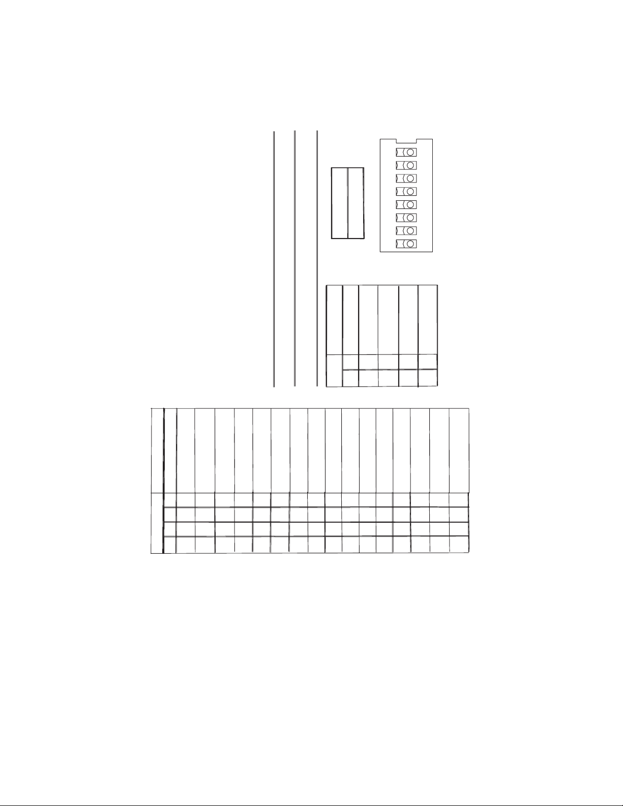
6.7 AGITATION - CONTROLS, EXPANDED VIEW, SERIES 4500 IBD
876
OFF
ON
=
=
X
FOR PELLET CAPABLE
DISPENSERS ONLY
PELLET ICE SETTING:
AGITATION ON TIME: 4 SEC.
OFF TIME: 150 MIN.
SWITCHES 5-8 : AGITATION "OFF TIME"
CUBE ICE SETTING:
AGITATION ON TIME: 2 SEC.
OFF TIME: 60 MIN.
AGITATION
OFF TIME
8
7
EXPANDED VIEW OF CONTROLS
6
SWITCH NUMBER
5
10 MINUTES
NO AGITATION
O
X
O
O
O
O
O
OO
SWITCH 1 : "LOW ICE" LED INDICATOR
20 MINUTES
30 MINUTES
X
O
X
X
O
O
O
SWITCHES 3-4 : AGITATION "ON TIME"
SWITCH 2 : "LOW ICE" ALARM
40 MINUTES
50 MINUTES
60 MINUTES
O
O
XXX
O
XXXX
O
O
70 MINUTES
X
OOO
O
ON TIME
AGITATION
4
3
SWITCH
NUMBER
90 MINUTES
80 MINUTES
X
O
O
O
OO
X
XXX
ON
1 SECOND
2 SECOND
X
OOO
100 MINUTES
O
X
O
X
120 MINUTES
110 MINUTES
X
O
O
X
O
X
X
51342
3 SECOND
4 SECOND
X
O
X
130 MINUTES
140 MINUTES
X
O
O
X
X
X
XX
SLIDE SWITCHES:
SLIDE SWITCH UP TO TURN "ON"
SLIDE SWITCH DOWN TO TURN "OFF"
150 MINUTES
X
X
X
X
LED
INDICATORS
SWITCH IS CLOSED
D3-ON WHEN ICE DISPENSE
D4-ON WHEN LID IS CLOSED
AVAILABLE
D5-ON WHEN +5VDC IS AVAILABLE
D6-ON WHEN +32VDC IS
SOLENOID IS OPEN
D7-FLASHES WHEN ICE IS LOW
D8-ON WHEN TRAP DOOR
D9-ON WHEN MOTOR IS ON
34
Page 35

6.8 PLUMBING DIAGRAM
RECOMMENDED PLUMBING
8 7 6 3 2 1
SODA/WATER #5
SODA/WATER #4
SODA/WATER #1,2,3
5 4
SODA/WATER #6,7,8
SYRUP #1
SYRUP #2
SYRUP LINES NOT SHOWN
3-1-1-3 CONFIGURATION
FOR ASSISTANCE CALL 1-800-729-1500
PART NO: 06-2226
SYRUP #3
SYRUP #4
SYRUP #5
SYRUP #6
SYRUP #7
SYRUP #8
7. DISPENSER DISPOSAL
To prevent possible harm to the environment from improper disposal, recycle the unit
by locating an authorized recycler or contact the retailer where the product was pur
chased. Comply with local regulations regarding disposal of the refrigerant and
insulation.
35
Page 36

Lancer Corp.
800-729-1500
Technical Support/Warranty: 800-729-1550
custserv@lancercorp.com
lancercorp.com
 Loading...