

Page 1
FLAVOR SELECT 22 (FS) ICE BEVERAGE DISPENSER
Operation Manual
PN: 28-0580/03
FS22
Lancer Corp.
6655 Lancer Blvd.
San Antonio, Texas 78219
800-729-1500
Technical Support/Warranty: 800-729-1550
custserv@lancercorp.com
lancercorp.com
Manual PN: 28-0580/03
MARCH 2013
FOR QUALIFIED INSTALLER ONLY
“Lancer” is the registered trademark of Lancer © 2014 by Lancer, all rights reserved.
Page 2

ABOUT THIS MANUAL
This booklet is an integral and essential part of the product and should be handed over to the operator after the
installation and preserved for any further consultation that may be necessary. Please read carefully the guidelines and
warnings contained herein as they are intended to provide the user with essential information for the continued safe
use and maintenance of the product. In addition, it provides GUIDANCE ONLY to the user on the correct services and
site location of the unit.
The installation and relocation, if necessary, of this product must be carried out by qualied personnel with up-to-date
safety and hygiene knowledge and practical experience, in accordance with current regulations.
TABLE OF CONTENTS
ABOUT THE FS22 DISPENSERS/SPECIFICATIONS.......................................................................3
PRE-INSTALLATION CHECKLIST......................................................................................................4
SAFETY/WARNINGS........................................................................................................................5-7
1. INSTALLATION..............................................................................................................................8
1.1 UNPACKING THE DISPENSER............................................................................................8
1.2 DRAIN SPIDER.....................................................................................................................8
1.3 SELECTING A LOCATION FOR THE DISPENSER.............................................................9
1.4 INSTALLING AN ICEMAKER...........................................................................................9-10
1.5 LEVELING THE DISPENSER.............................................................................................10
1.6 CONNECTING TO WATER SUPPLY LINES..................................................................10-11
1.7 INSTALLATION OVERVIEW..........................................................................................11-12
1.8 CONNECTING CO2...........................................................................................................12
1.9 CONNECTING TO ELECTRICAL POWER.........................................................................13
1.10 INSTALLING THE FS30 DISPENSER...........................................................................13-14
2. CLEANING AND SANITIZING.....................................................................................................14
2.1 GENERAL INFORMATION.................................................................................................14
2.2 CLEANING AND SANITIZING SOLUTIONS..................................................................14-15
2.3 DAILY CLEANING..........................................................................................................15-16
2.4 ICE BIN CLEANING - PERFORM AT STARTUP AND MONTHLY......................................16
2.5 CLEANING/SANITIZING BEVERAGE COMPONENTS - BAG-IN-BOX SYSTEMS..........17
2.6 ICE CHUTE CLEANING......................................................................................................17
3. HOW TO OPERATE AND ADJUST THE DISPENSER..............................................................17
3.1 NORMAL OPERATION........................................................................................................17
3.2 PROGRAMMING AND SETUP SOFTWARE.................................................................18-19
3.3 PURGING THE CARBONATION SYSTEM.........................................................................19
3.4 PURGING THE WATER AND SYRUP SYSTEMS..............................................................20
3.5 ADJUSTING WATER FLOW AND WATER TO SYRUP RATIO (BRIX)..............................20
3.6 CARBONATOR PUMP MODIFICATIONS...........................................................................20
4. TROUBLESHOOTING............................................................................................................21-25
5. DISPENSER DISPOSAL.............................................................................................................25
6. ILLUSTRATIONS, PARTS LISTINGS, AND WIRING DIAGRAMS............................................26
6.1 FINAL ASSEMBLY.........................................................................................................26-27
6.2 ICE CHUTE ASSEMBLY......................................................................................................28
6.3 PELLET ICE ASSEMBLY AND PARTS LISTING................................................................29
6.4 LANCER FLOW CONTROL VALVE (LFCV).......................................................................30
6.5 WIRING DIAGRAM..............................................................................................................31
6.6 PLUMBING DIAGRAM WITH VALVE WIRING...................................................................32
6.7 FS22COUNTER CUTOUT...................................................................................................33
2
Page 3
ABOUT THE FS22
The FS22 is designed using the highest quality materials and state-of-the-art technology
providing our customers with consistent quality and a unique drink experience.
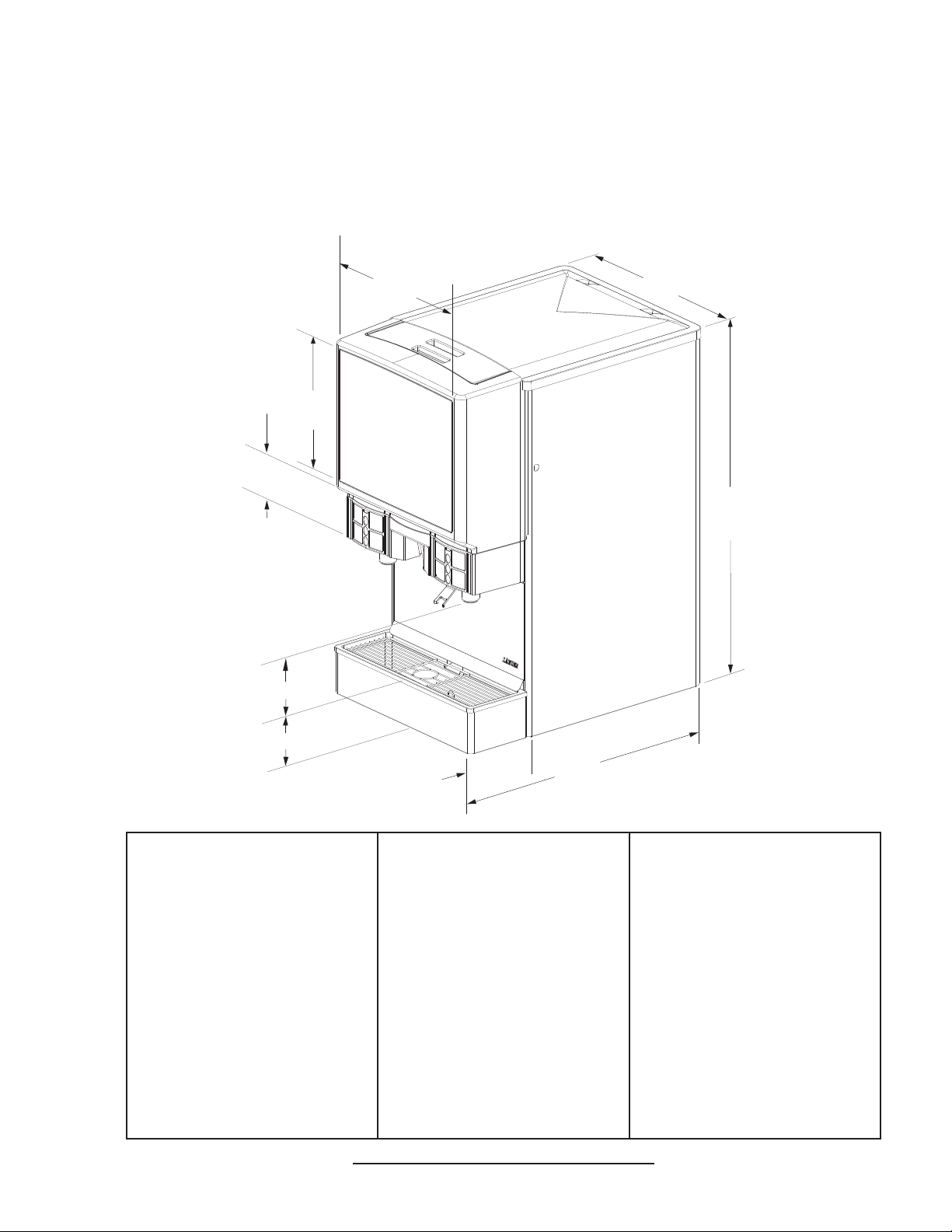
FS22 SPECIFICATIONS
22”
17 5/8”
14 3/8”
(365 mm)
4 1/2”
(114 mm)
(559 mm)
40 1/4”
( 986 mm)
10”
(254 mm)
5 1/8”
(130 mm)
DIMENSIONS
Width: 22 in (559 mm)
Depth: 30.5 in (775 mm)
Height: 40.25 in (1022 mm)
SPACE REQUIRED
Left Side: 1 in (25 mm)
Right side: 1 in (25 mm)
Back: 1 in (25 mm)
Top: 6 in (152 mm)
Optional legs: 4 in (102 mm)
ELECTRICAL
220/230 VAC,50\60Hz,3.5AMPs
115 VAC, 60 Hz, 7 amps
7 1/2”
(190 mm)
WEIGHT
Without ice: 280 lbs (127 kg)
With ice: 480 lbs (218 kg)
Shipping: 310 lbs (141 kg)
ICE
Capacity: 200 lbs (91 kg)
Dispensable: 170 lbs (77 kg)
FITTINGS
Water for carbonator inlet:
3/8” barb
Plain water inlet: 3/8” barb
Brand syrup inlets: 3/8” barb
Injection avor inlets: 1/4” barb
CO2 inlet: 3/8” barb
30 1/2”
(775 mm)
PLAIN WATER SUPPLY
Min owing pressure: 75 PSIG
(0.517 MPA)
CARBONATOR WATER SUPPLY
Min owing pressure: 25 PSIG
(0.172 MPA)
Max static pressure: 50 PSIG
(0.345 MPA)
CARBON DIOXIDE (CO2)
Min pressure: 70 PSIG
(0.483 MPA)
Max pressure: 80 PSIG
(0.552 MPA)
This unit emits a sound pressure level below 70 dB
3
Page 4
PRE-INSTALLATION CHECKLIST
BEFORE GETTING STARTED
Each unit is tested under operating conditions and is thoroughly inspected before
shipment. At the time of shipment, the carrier accepts responsibility for the unit. Upon
receiving the unit, carefully inspect the carton for visible damage. If damage exists, have
the carrier note the damage on the freight bill and le a claim with carrier. Responsibility for
damage to the dispenser lies with the carrier.
TOOLS REQUIRED
Oetiker Pliers Slotted Screwdriver
Tubing Cutters Phillips Screwdriver
Wrench
POST MIX ACCESSORIES
CO2 Regulator Set CO2 Supply
Beverage Tubing Oetiker Clamps/Fittings
Water Booster Water Regulator
BIB SYSTEM
BIB Rack BIB Regulator Set
BIB Syrup Boxes
BIB Connectors - ensure you have the correct connectors for syrup lineup.
CONSIDER LOCATION OF THE FOLLOWING PRIOR TO INSTALL
Water supply lines Drain
Is the countertop level? Heating and air conditioning ducts
Grounded electrical outlet.
Enough space to install the dispenser. Include space for a top-mounted ice machine, if necessary.
Does the top-mounted ice machine have a minimum clearance on all sides?
Located away from direct sunlight or overhead lighting.
Can the countertop support the weight of the dispenser? Be sure to include the weight of an ice
machine (if necessary) plus the weight of the ice.
This unit is not suitable for use in an area where a water jet could be used.
4
Page 5
!
!
! The dispenser is for indoor use only. This appliance is intended for use in commercial applications such as
WARNING/ADVERTENCIA/AVERTISSEMENT
restaurants, stores or similar. This unit is not a toy. It should not be used by children or inrm persons without
supervision. This appliance is not intended for use by persons (including children) with reduced physical, sensory
or mental capabilities, or lack of experience and knowledge, unless they have been given supervision or instruction
concerning use of the appliance by a person responsible for their safety. Cleaning and user maintenance shall not
be performed by children without supervision. This unit is not designed to dispense dairy products. The minimum/
maximum ambient operating temperature for the dispenser is 40°F to 90°F (4°C to 32°C). Do not operate unit below
minimum ambient operation conditions. Should freezing occur, cease operation of the unit and contact aurthorized
service technician. Service, cleaning and sanitizing should be accomplished only by trained personnel. Applicable
safety precautions must be observed. Instruction warnings on the product being used must be followed.
! El dispensador sólo debe usarse en interiores. Esta unidad está diseñada para su uso en aplicaciones
comerciales tales como restaurantes, tienda o similares. Esta unidad no es un juguete. No la deben usar niños ni
personas discapacitadas sin supervisión. Esta unidad no está destinada al uso por parte de personas (incluso niños)
con capacidad física, sensorial o mental reducida, o sin experiencia y conocimientos sucientes, a menos que una
persona responsable de su seguridad les haya dado supervisión o capacitación en el uso de la unidad. Limpieza y
mantenimiento de usuario no deberá ser realizada por los niños sin supervisión. Esta unidad no ha sido diseñada
para suministrar productos lácteos. La temperatura ambiente operativa mínima / máxima para el dispensador es de
40°F a 90°F (4°C a 32°C). No opere la unidad por debajo de las condiciones mínimas de funcionamiento ambiente.
En caso de ocurrir congelación, cesar la operación de la unidad y póngase en contacto con el servicio técnico
autorizado. Servicio de limpieza y desinfección debe llevarse a cabo solamente por personal especializado.
Precauciones de seguridad aplicables deben ser observadas. Advertencias de instrucciones en el producto que se
use debe ser seguido.
! Le distributeur est destiné à un usage à l’intérieur seulement. Cet appareil est conçu pour une utilisation dans des
applications commerciales telles que les restaurants, les dépanneurs ou similaires. Cet appareil n’est pas un jouet. Il
ne devrait pas être utilisé par des enfants ou des personnes inrmes sans surveillance. Cet appareil n’est pas destiné
à un usage par des personnes (y compris les enfants) ayant des capacités physiques, sensorielles ou mentales
réduites, ou manquant d’expérience et de connaissances, à moins qu’elles obtiennent de la surveillance ou des
instructions au sujet de l’utilisation de l’appareil de la part d’une personne chargée de leur sécurité. Nettoyage et
entretien de l’utilisateur ne doivent pas être effectués par des enfants sans surveillance. Cet appareil n’est pas conçu
pour distribuer des produits laitiers. La température de service ambiante minimum/maximum pour le distributeur est
de 40°F à 90°F (4°C à 32°C). Ne pas faire fonctionner l’appareil ci-dessous les conditions minimales de
fonctionnement ambiantes. Faut-gel se produisent, cesser l’exploitation de l’appareil et contactez technicien agréé.
Service de nettoyage et de désinfection doivent être effectuées uniquement par du personnel qualié. Les mesures
de sécurité applicables doivent être respectées. Avertissements Instruction sur le produit utilisé doit être suivie.
CO2/CARBON DIOXIDE /EL ANHÍDRIDO CARBÓNICO/
5
DIOXYDE DE CARBONE
5
5 Carbon Dioxide (CO2) is a colorless, noncombustible gas with a light pungent odor. High percentages of CO2 may
displace oxygen in the blood. Prolonged exposure to CO2 can be harmful. Personnel exposed to high concentrations
of CO2 gas will experience tremors which are followed by a loss of consciousness and suffocation. If a CO2 gas leak
is suspected, immediately ventilate the contaminated area before attempting to repair the leak. Strict attention must
be observed in the prevention of CO2 gas leaks in the entire CO2 and soft drink system.
5 El anhídrido carbónico (CO2) es un gas incoloro, no combustible, con un olor pungente ligero. Altos porcentajes
de CO2 en la sangre pueden desplazar el oxígeno en la sangre. La exposición prolongada al CO2 puede ser nociva.
El personal expuesto a concentraciones altas de CO2 sufre temblores seguidos de la pérdida de la consciencia y
sofocación. Si se sospecha que existe una pérdida de CO2, ventile el área contaminada antes de tratar de reparar
la pérdida. Hay que prestar suma atención para evitar pérdidas de CO2 en todo el sistema de CO2 y de bebidas
gaseosas.
5 Le dioxyde de carbone (CO2) est plus lourd que l’air et déplace l'oxygène. Le CO2 est un gaz incolore et
incombustible, ayant une odeur un peu âcre. Des concentrations fortes de CO2 peuvent déplacer l'oxygène dans le
sang. Une exposition prolongée au CO2 peut être nocive. Le personnel exposé à de fortes concentrations de CO2
gazeux éprouvera des tremblements, suivis rapidement d'une perte de conscience et de suffocation. On doit faire très
attention de prévenir les fuites de CO2 gazeux dans le système entier de CO2 et de boisson gazeuse. Si on suspecte
qu'il y a une fuite de CO2 gazeux, aérez le secteur contaminé immédiatement avant d'essayer de réparer la fuite.
5
Page 6
ELECTRICAL WARNING/ADVERTENCIA ELÉCTRICA/
F F
AVERTISSEMENT ÉLECTRIQUE
F Check the dispenser serial number plate for correct electrical requirements of unit. Do not plug into a wall
electrical outlet unless the current shown on the serial number plate agrees with local current available. Follow all
local electrical codes when making connections. If supply cord is damaged, it must be replaced by the manufacturer
or an authorized service agent to avoid hazard or injury. Each dispenser must have a separate electrical circuit. Do
not use extension cords with this unit. Do not ‘gang’ together with other electrical devices on the same outlet. The
keyswitch does not disable the line voltage to the transformer primary. Always disconnect electrical power to the unit
to prevent personal injury before attempting any internal maintenance. The resettable breaker switch should not be
used as a substitute for unplugging the dispenser from the powersource to service the unit. Only qualied personnel
should service internal components of electrical control housing. Make sure that all water lines are tight and units are
dry before making any electrical connections!
F Verique la placa con el número de serie del dispensador, donde encontrará los requisitos eléctricos correctos de
la unidad. No enchufe la unidad en un tomacorriente de pared a menos que la corriente indicada en la placa con el
número de serie concuerde con la corriente local disponible. Si el cable de alimentación está dañado, debe ser
reemplazado por el fabricante o un agente de servicio autorizado para evitar riesgos o lesiones. Al hacer las
conexiones, respete todos los códigos eléctricos locales. Cada dispensador debe tener un circuito eléctrico
independiente. No use extensiones con esta unidad. No la conecte junto con otros dispositivos eléctricos al mismo
tomacorriente. El interruptor de llave no corta el voltaje de línea al transformador primario desconecte siempre la
alimentación eléctrica a la unidad para evitar lesiones personales antes de tratar de realizar tareas de
mantenimiento. El disyuntor de sobrecarga reseteable no se debe usar como sustituto para desenchufar el
dispensador de la fuente de alimentación para realizar tareas de servicio de la unidad. El servicio de los
componentes internos de la caja de control eléctrico debe conarse exclusivamente a personal calicado. Asegúrese
de que todas las líneas de agua estén ajustadas y las unidades estén secas antes de hacer conexiones eléctricas.
F Examinez la plaque de numéro de série du distributeur pour connaître les bonnes exigences en matière
d’électricité pour l’appareil. Ne le branchez pas à une prise électrique murale à moins que le courant indiqué sur la
plaque de numéro de série corresponde au courant local disponible. Si le cordon d’alimentation est endommagé, il
doit être remplacé par le fabricant ou un technicien agréé pour éviter tout danger ou de blessure. Respectez tous
les codes électriques locaux lorsque vous faites des connexions. Chaque distributrice doit avoir un circuit électrique
séparé. N’utilisez pas de cordons prolongateurs avec cet appareil. Ne pas le brancher avec d’autres appareils
électriques sur la même prise. L’interrupteur à clé ne coupe pas la tension secteur au transformateur primaire.
Débranchez toujours le courant électrique à l’appareil, an de prévenir des blessures, avant de faire un entretien
interne quelconque. Le disjoncteur réarmable ne devrait pas être utilisé au lieu de débrancher le distributeur de la
source d’alimentation en électricité pour faire de l’entretien/une réparation de l’appareil. Seul le personnel qualié
devrait faire l’entretien/la réparation des composants internes dans le logement des commandes électriques.
Assurez-vous que toutes les conduites d’eau sont étanches et que les appareils sont secs avant de faire des
connexions électriques!
AUTOMATIC AGITATION/AGITACIÓN AUTOMÁTICA/
! Units equipped with automatic agitation and will activate unexpectedly. Do not place hands or foreign objects in
the ice storage unit compartment. Unplug the dispenser during servicing, cleaning and sanitizing.
! Las unidades equipadas con agitación se activan repentinamente. No ponga las manos ni obetos extraños
en el compartimiento de almacenamiento de hielo. Desenchufe el dispensador durante tareas de servicio, limpieza y
esterilzación.
! Les appareils sont munis d’agitation automatique et s’activeront de manière imprévue. Ne placez pas vos mains
ou des corps étrangers dans le compartiment de stockage de l’appareil. Débranchez le distributeur pendant son
entretien, son nettoyage et sa désinfection.
6
Page 7
WATER NOTICE/ADVERTENCIA DE SUMINISTRO DE
! !
AGUA/AVERTISSEMENT D’ALIMENTATION DE L’EAU
! Provide an adequate potable water supply. Water pipe connections and xtures directly connected to a potable
water supply must be sized, installed, and maintained according to federal, state, and local laws. The water
supply line must be at least a 3/8 inches (9.525 mm) pipe with a minimum of 75 PSI (0.517 MPA) line pressure, but
not exceeding a maximum of 125 PSI (0.860 MPA). Water pressure exceeding 125 PSI (0.860 MPA) must be reduced
to 125 PSI (0.860 MPA) with the provided pressure regulator. Use a lter in the water line to avoid equipment damage
and beverage off-taste. Check the water lter periodically, as required by local conditions. The water supply must be
protected by means of an air gap, a backow prevention device (located upstream of the CO2 injection system) or
another approved method to comply with NSF standards. A leaking inlet water check valve will allow carbonated
water to ow back through the pump when it is shut off and contaminate the water supply. Ensure the backow
prevention device complies with ASSE and local standards. It is the responsibility of the installer to ensure compliance.
! Proporcione un suministro adecuado de agua potable. La línea de suministro de agua debe ser de una tubería de
por lo menos 3/8 pulgadas (9.525 mm) con una presión de línea mínima de 75 PSI (0.517 MPAr) , pero sin superar
el máximo de 125 PSI (0.860 MPA). La presión de agua que supere los 125 PSI (0.860 MPAr) se debe reducir a 125
PSI (0.860 MPA) con un regulador de presión. Use un ltro en la línea de agua para evitar daños al equipo y cierto
sabor raro en las bebidas. Verique periódicamente el ltro de agua de acuerdo con las condiciones imperantes. El
suministro de agua debe estar protegido por una separación de aire, un dispositivo de prevención del contraujo
(situado antes del sistema de inyección de CO2) u otro método aprobado para cumplir las normas NSF. Si la válvula
de retención de entrada de agua tuviera pérdidas, permitiría el contraujo del agua carbonatada a través de la
bomba cuando se la detiene y contaminaría el suministro de agua. Asegúrese de que el dispositivo de prevención del
contraujo cumpla con las normas locales y de ASSE. Es responsabilidad del instalador cumplir con estos requisitos.
! Fournissez une alimentation en eau potable adéquate. Les connexions et les dispositifs de conduite d'eau
connectés directement à une alimentation en eau potable doivent être calibrés, installés et maintenus selon les lois
fédérales, provinciales et locales. La conduite d'alimentation en eau doit être un tuyau d’au moins 3/8 pouces (9.525
millimètres) avec une pression de ligne minimum de 75 LPC (0.517 MPA), mais ne doit pas dépasser un
maximum de 125 (0.860 MPA). Une pression d'eau de plus de 125 LPC (0.860 MPA) doit être réduite à 125 LPC
(0.860 MPA)avec le régulateur de pression fourni. Utilisez un ltre dans la conduite d’eau pour éviter des dommages
à l’équipement et un goût des boissons qui n’est pas juste. Vériez le ltre à eau périodiquement, selon les exigences
des conditions locales. L’alimentation en eau doit être protégée au moyen d’un intervalle d’air, un disconnecteur
hydraulique (situé en amont du système d'injection de CO2) ou une autre méthode approuvée pour se conformer
aux normes de la NSF. Un clapet antiretour pour l’eau entrante qui fuie permettra à l'eau gazeuse de repasser par la
pompe quand elle est fermée et de contaminer l'alimentation en eau. Assurez-vous que le disjoncteur hydraulique
soit conforme aux normes de l’ASSE et locales. L’installateur est responsable d'assurer la conformité.
i ICE INFORMATION i
Dispensers using cubed ice may also use pellet ice if properly congured. Contact Lancer Customer Service or your
Sales Representative for more information.Lancer dispensers will not dispense shaved or aked ice. Do use bagged
ice. Bagged ice will damage components.
Dispensadores con cubitos de hielo también puede usar el hielo pellet si está bien congurado. Comuníquese con
el Servicio al Cliente Lancer o su representante de ventas para distribuidores information.Lancer más no dispensará
afeitado o en copos de hielo. Hacer uso de hielo en bolsas. Hielo en bolsas dañará los componentes.
Distributeurs à l’aide de glaçons peut aussi utiliser de la glace à granulés s’il est correctement conguré. Contactez le
service clientèle Lancer ou votre représentant des ventes pour les distributeurs information.Lancer plus ne distribue
pas rasé ou en ocons de glace. Faire utiliser de la glace en sac. Glace en sac endommager les composants.
7
Page 8
1. INSTALLATION
THINGS TO CONSIDER:
Connecting lines can be run through the back of the dispenser or extend down through a counter cutout.
Seal the dispenser directly on the countertop.
1.1 UNPACKING THE DISPENSER
A. Set shipping carton upright on the oor. Cut band and remove. Remove any staples that
secure the shipping board and lid to the carton. Open top of carton and remove interior
packing.
B. Lift carton up and off of the dispenser. Remove wood shipping base from the bottom of the
dispenser. (Support dispenser while removing shipping base to prevent damage to the
dispenser.)
C. Remove installation parts kits from the ice compartment.
D. Inspect unit and parts for concealed damage(s). If damage exists, notify delivering carrier
and le a claim against the carrier.
E. To remove the merchandiser: remove the two (2) screws on the Faucet Plate that secure
the merchandiser. The two (2) screws are located (from the left), above the second and
third nozzle and the sixth nozzle.
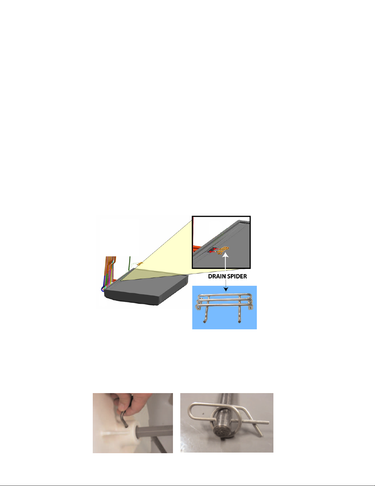
1.2 DRAIN SPIDER
The drain spider (Fig 1) is located directly in the center of the bin under the ice shroud. The
coldplate has a cavity designed to hold the drain spider. During shipment or installation, the
drain spider may become dislodged from its original position. Prior to installing the dispenser,
ensure the drain spider is in the correct position. This will prevent drain clog issues. Inspect the
lower bin area and reach under the shroud to ensure the drain spider is secure in the coldplate
cutout.
FIGURE 1
If the drain spider is not in place, proceed with the following steps:
A. Remove agitator clip and pin from agitator bar.
B. Remove agitator bar from paddle wheel.
C. Remove paddle wheel.
D. Remove ice shroud by lifting back then out of bin.
E. Locate drain spider and reinstall in the coldplate cavity where drain line exits (see gure above).
F. Reinstall all components. Ensure agitator clip is locked.
FIGURE 2
8
Page 9
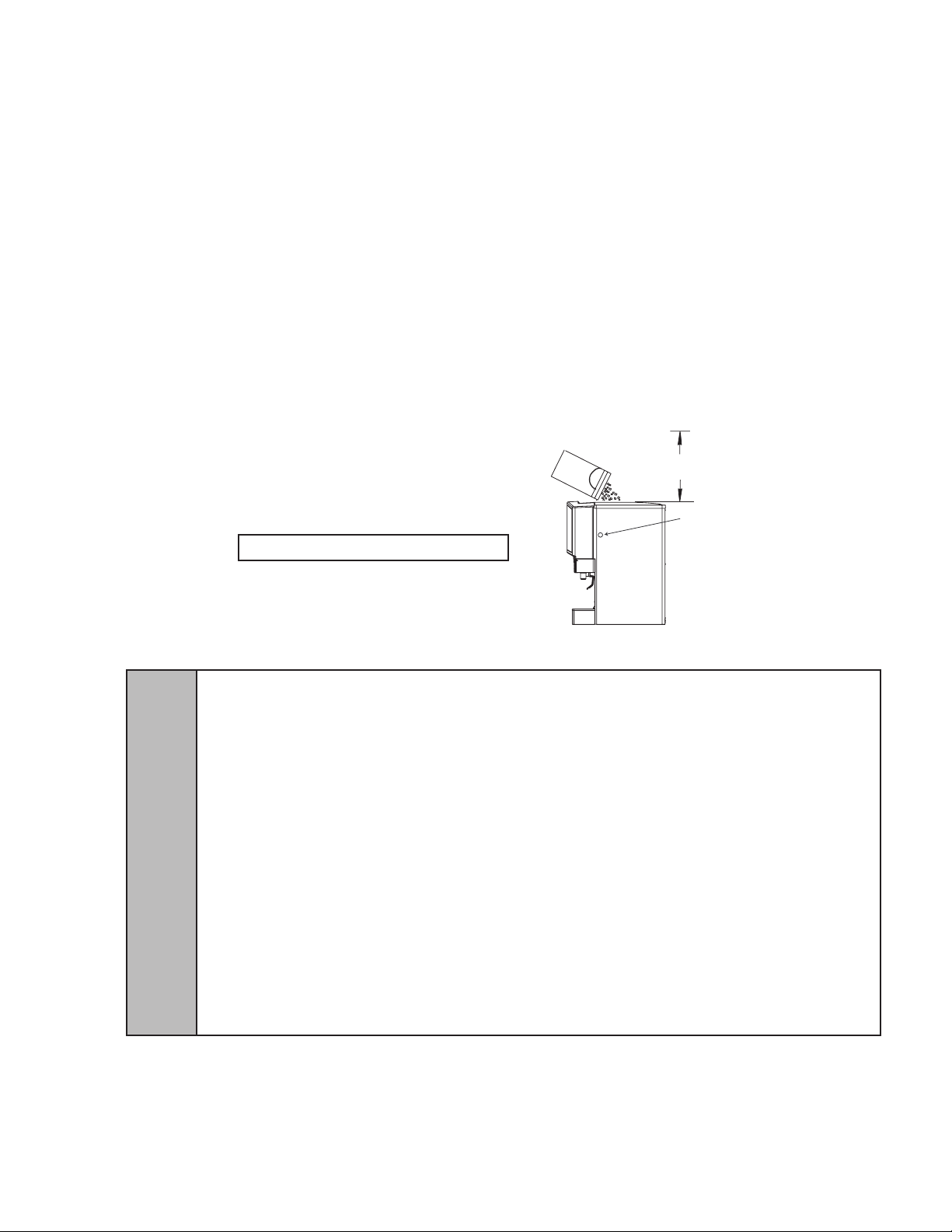
1.3 SELECTING A LOCATION
ENSURE SUFFICIENT CLEARANCE
FOR FILLING WITH ICE
FS22 DISPENSER, NO ICEMAKER
ENSURE KEYSWITCH
IS ACCESSIBLE
Connecting lines can be run through the back of the dispenser or extend down through a counter
cutout. Seal the dispenser directly on the countertop. Counter Cutouts are located in the Section 5.
Illustrations, Parts Listings and Wiring Diagrams.
A. Select a level, well ventilated, accessible location away from direct sunlight (avoid) or overhead
lighting (convenient to water, soda, and syrup lines and open type drain), a properly grounded
electric supply and ensure sufcient clearance for air circulation.
B. Sufcient clearance must be provided, if an ice maker is not installed, to allow lling the ice
compartment from a ve gallon bucket (a minimum of 16 inches (106.4 mm) is recommended),
refer to Fig 3. Lancer does NOT recommend the use of shaved or ake ice in the dispenser.
B. The selected location should be able to support the weight of the dispenser, ice and possibly
an ice maker being installed after counter cut out is made. Total weight (with ice maker) could
exceed 800 pounds (363.6kg).
C. Unit may be installed directly on the countertop or on legs. If installed directly on the counter,
the unit must be sealed to the countertop with an FDA approved sealant. If an ice maker is to
be mounted on top of dispenser, do not install dispenser on legs.
D. The dispenser is only to be installed in locations where it can be overseen by trained personnel.
NOTE: The ice level should not exceed the height of the metal bin wall when lled manually (Fig 3).
FIGURE 3. Unit Displayed (no icemaker)
NOTE: Fill ice with merchandiser intact.
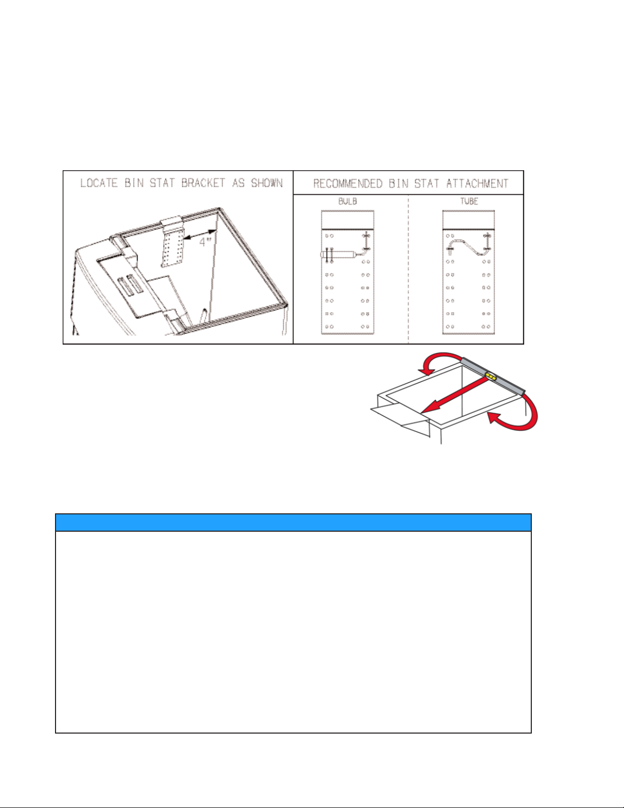
1.4 INSTALLING AN ICEMAKER
WARNING WHEN INSTALLING AN ICEMAKER ON THE DISPENSER, USE A BIN THERMOSTAT TO CONTROL THE
ICE LEVEL (SEE BELOW). THIS WILL PREVENT DAMAGE TO THE DISPENSING MECHANISM. THE BRACKET
FOR MOUNTING A THERMOSTAT IS LOCATED IN THE ICE BIN. DURING THE AUTOMATIC AGITATION CYCLE AND
WHILE DISPENSING ICE, ENSURE THERE IS ADEQUATE SPACE BETWEEN THE TOP OF THE ICE LEVEL AND
THE BOTTOM OF THE ICEMAKER SO THE ICE CAN MOVE WITHOUT OBSTRUCTION. CONTACT YOUR ICEMAKER
MANUFACTURER FOR INFORMATION ON A SUITABLE BIN THERMOSTAT.
ADVERTENCIA CUANDO INSTALA UNA MÁQUINA DE CUBITOS EN EL DISPENSADOR, USE UN TERMOSTATO DE
RECIPIENTE PARA CONTROLAR EL NIVEL DE HIELO (VER MÁS ABAJO). DE ESTA FORMA SE EVITAN LOS DAÑOS
AL MECANISMO DISPENSADOR. EL SOPORTE PARA MONTAR EL TERMOSTATO ESTÁ EN EL RECIPIENTE DEL
HIELO. DURANTE EL CICLO AUTOMÁTICO DE AGITACIÓN Y CUANDO SE DISPENSA HIELO, ASEGÚRESE DE QUE
HAYA ESPACIO ADECUADO ENTRE LA PARTE SUPERIOR DEL NIVEL DE HIELO Y LA PARTE INFERIOR DE LA
MÁQUINA DE CUBITOS, DE MODO QUE EL HIELO SE MUEVA SIN OBSTRUCCIONES. COMUNÍQUESE CON EL
!
A. Install the icemaker per manufacturer specications. Points of consideration include drainage,
FABRICANTE DE SU MÁQUINA DE CUBITOS PARA OBTENER INFORMACIÓN SOBRE UN TERMOSTATO DE
RECIPIENTE ADECUADO.
AVERTISSEMENT LORS DE L’INSTALLATION D’UN APPAREIL À CUBES DE GLACE SUR LE DISTRIBUTEUR,
UTILISEZ UN THERMOSTAT DE BAC POUR CONTRÔLER LE NIVEAU DE GLACE (VOIR CI-DESSOUS). CECI
EMPÊCHERA LES DOMMAGES AU MÉCANISME DE DISTRIBUTION. LE SUPPORT POUR FIXER UN THERMOSTAT
SE TROUVE DANS LE BAC DE GLACE. PENDANT LE CYCLE D’AGITATION AUTOMATIQUE ET LORS DE LA
DISTRIBUTION DE LA GLACE, ASSUREZ-VOUS QU’IL Y A ASSEZ D’ESPACE ENTRE LE DESSUS DU NIVEAU DE
GLACE ET LE FOND DE L’APPAREIL À CUBES DE GLACE, POUR QUE L’APPAREIL À CUBES DE GLACE PUISSE
BOUGER SANS OBSTRUCTION. CONTACTEZ VOTRE FABRICANT D’APPAREILS À CUBES DE GLACE POUR
OBTENIR DES INFORMATIONS SUR UN THERMOSTAT DE BAC APPROPRIÉ.
ventilation, and drop zones.
B. An adapter plate is required when installing an icemaker. Contact your Sales Representative
or Lancer Customer Service for more information.
9
Page 10
1.4 INSTALLING AN ICEMAKER (CONTINUED)
C. A bin thermostat is required in order to control the level of ice in the dispenser (Refer to
WARNING on previous page). Contact your icemaker manufacturer to obtain the correct bin
thermostat. The bin thermostat should be a minimum of 2” (50.8 mm) below the top edge of the
dispenser. The preferred location of the bin thermostat is on the right side wall above the auger.
D. Ensure the icemaker is installed properly to allow for removal of the merchandiser.
E. Ensure manual ll is accessible.
F. Clean and maintain icemaker per manufacturer’s instructions.
FIGURE 4
1.5 LEVELING THE DISPENSER
In order to facilitate proper dispenser drainage and
carbonation, ensure that the dispenser is level, front to
back and side to side. Place a level on the top of the rear
edge of the dispenser. The bubble must settle between
the level lines (Fig 5). Repeat this procedure for the
remaining three sides. Level unit if necessary. For
optimum performance place the unit at a 0 degree tilt. The
maximum tilt is 5 degrees.
FIGURE 5
1.6 CONNECTING TO WATER SUPPLY LINES
NOTE: In addition to the following, adhere to WATER SUPPLY WARNINGS AND CAUTIONS,
Page 7.
WATER NOTICE
For the plain water supply line, the inlet water owing pressure should be at least 75 PSI (0.517 MPA). If the water
pressure is lower than 75 PSI (0.517 MPA) owing, use a water booster system.
If the water owing pressure is lower than 75 PSI (0.517 MPA) at the plain water inlet and a water booster is NOT
installed, water products will not hold a proper ow rate or water/syrup ratio. Flow conditions at the nozzle can also
be affected, causing poor nozzle coning and mixing.
For the soda water supply line, do not exceed 50 PSI (0.345 MPA) for the inlet water static pressure going into the
carbonator pump. If the static water pressure exceeds 50 PSI (0.345 MPA), install a water regulator before the
carbonator water inlet.
The Lancer Water Booster/Tank (PN MC-163172) is offered as a kit. The water booster must be installed as close
as possible to the plain water circuit inlet.
Install the water regulator (Lancer PN 18-0306) included with unit as close as possible to the water carbonator
pump inlet. The recommended water pressure value feeding the carbonator is a minimum of 25 PSI (0.172 MPA). If
the normal water pressure does not exceed 50 PSI (0.345 MPA), but uctuates over this value (for example, when
water usage on other equipment connected to the same water supply causes pressure spikes), use a water
regulator.
10
Page 11
1.6 CONNECTING TO WATER SUPPLY LINES (CONTINUED)
A. Installer should provide new beverage tubing that meets the IEC Standard 61770. Do not reuse
beverage tubing. Lancer beverage tubing kits are available for purchase. Contact your Sales
Representative or Lancer Customer Service for more information. Use a lter in the water line.
Failure to do so can result in equipment damage and beverage off-taste. Check the water lter
periodically, as required by local conditions.
CAUTION FAILURE TO DISCONNECT THE MOTOR POWER SUPPLY WILL DAMAGE THE CARBONATOR
MOTOR, THE PUMP AND VOID THE WARRANTY.
PRECAUCIÓN SI NO DESCONECTA LA ALIMENTACIÓN ELÉCTRICA DEL MOTOR PODRÍAN DAÑARSE LA BOMBA
Y EL MOTOR DEL CARBONATADO Y ANULAR LA GARANTÍA.
!
ATTENTION LE FAIT DE NE PAS MAINTENIR LE DÉGAGEMENT SPÉCIFIÉ FERA SURCHAUFFER LE
COMPRESSEUR ET AURA COMME CONSÉQUENCE UNE DÉFAILLANCE DU COMPRESSEUR.
B. Protect the water supply by means of an air gap, a backow prevention device, or another
approved method that complies with NSF standards. A leaking inlet water check valve will
allow carbonated water to ow back through the pump when it is shut off and contaminate
the water supply. Ensure the backow prevention device complies with ASSE and local
standards. It is the responsibility of the installer to ensure compliance.
C. Provide an adequate potable water supply. Water pipe connections and xtures directly
connected to a potable water supply must be sized, installed, and maintained according to
federal, state, and local laws.
CAUTION DO NOT CONNECT TO A HOT WATER OR SOFT WATER SOURCE. THIS CAUSES EXCESSIVE
FOAMING.
PRECAUCIÓN NO LO CONECTE A UNA FUENTE DE AGUA CALIENTE O AGUA BLANDA. ESTO PROVOCA UN
EXCESO DE ESPUMA.
!
ATTENTION NE PAS RACCORDER À UN CHAUFFE-EAU OU D’UNE SOURCE D’EAU DOUCE. CELA PROVOQUE
UN MOUSSAGE EXCESSIF.AURA COMME CONSÉQUENCE UNE DÉFAILLANCE DU COMPRESSEUR.
1.7 INSTALLATION OVERVIEW
A. FIGURE 6: FS22-1
Carbonator
Pump Deck
Water
Regulator
Tee
Water
Booster
11
Page 12

1.7 INSTALLATION OVERVIEW (CONTINUED)
B. FIGURE 7: FS22-2
1.8 CONNECTING CO2
A. Provide a regulated CO2 supply to the dispenser through a 3/8 inch supply line. The maximum
pressure is 80 PSI (0.552 MPA).
CAUTION EXCESSIVE CO2 PRESSURE CAN DAMAGE COMPONENTS.
PRECAUCIÓN PRESIÓN DE CO2 EN EXCESO PUEDE DAÑAR LOS COMPONENTES.
!
ATTENTION UNE PRESSION EXCESSIVE PEUT ENDOMMAGER LES COMPOSANTS DE CO2.
12
Page 13

1.9 CONNECTING TO ELECTRICAL POWER
NOTE: In addition to the following, adhere to the ELECTRICAL Warnings and Cautions, page 6.
GROUNDING WARNING THE DISPENSER MUST BE PROPERLY ELECTRICALLY GROUNDED TO AVOID
SERIOUS INJURY OR FATAL ELECTRICAL SHOCK. THE POWER CORD HAS A THREE-PRONG GROUNDED
PLUG. IF A THREE-HOLE GROUNDED ELECTRICAL OUTLET IS NOT AVAILABLE, USE AN APPROVED METHOD TO
GROUND THE UNIT. FOLLOW ALL LOCAL ELECTRICAL CODES WHEN MAKING CONNECTIONS. EACH
DISPENSER MUST HAVE A SEPARATE ELECTRICAL CIRCUIT. DO NOT USE EXTENSION CORDS. DO NOT
CONNECT MULTIPLE ELECTRICAL DEVICES ON THE SAME OUTLET.
ADVERTENCIA, PUESTA A TIERRA ES NECESARIO PONER A TIERRA ELÉCTRICAMENTE EL
DISPENSADOR PARA EVITAR LESIONES GRAVES E INCLUSO ELECTROCHOQUES FATALES. EL CABLE DE
ALIMENTACIÓN TIENE UN ENCHUFE PUESTO A TIERRA DE 3 CLAVIJAS. SI NO SE DISPONE DE UN TOMA
ELÉCTRICO CONECTADO A TIERRA DE TRES AGUJEROS, USE UN MÉTODO APROBADO PARA PONER A TIERRA
LA UNIDAD. AL HACER LAS CONEXIONES, RESPETE TODOS LOS CÓDIGOS ELÉCTRICOS LOCALES. CADA
F
A. Check the dispenser serial number plate for correct electrical requirements of unit. Do not plug
1.10 INSTALLING THE FS22 DISPENSER
A. Remove the cup rest, drip tray, splash plate, and top cover from the unit.
B. Remove the cover plate at the back of the unit (if not a through-the-counter installation).
C. Connect the plain water supply line and the water supply for the carbonator to the 3/8 inch barb
NOTE: Install the water regulator (Lancer PN 18-0306) as close as possible to the water carbonator
D. Place the CO2 cylinder with the CO2 regulator in a serviceable location and route the CO2
supply line (75 PSI)(0.517 MPA) to the 3/8 inch barb tting at the front of the unit.
E. Connect the syrup supply lines to the 3/8 inch barb inlet ttings at the front of the unit. Connect
F. Connect the avor injection lines to the barb ttings at the front of the unit.
G. Install the drip tray and extend the hose to an open drain.
H. Insulate drain lines with a closed cell insulation. Ensure that the insulation covers the entire
I. Install the cup rest and splash plate.
J. Connect the power cord to a grounded electrical outlet.
DISPENSADOR DEBE TENER UN CIRCUITO ELÉCTRICO INDEPENDIENTE. NO USE CABLES DE EXTENSIÓN. NO
CONECTE VARIOS DISPOSITIVOS ELÉCTRICOS AL MISMO TOMACORRIENTE.
EXIGENCES DE MISE À LA TERRE LA DISTRIBUTRICE DOIT ÊTRE MISE À LA TERRE ÉLECTRIQUEMENT
CORRECTEMENT POUR ÉVITER DES BLESSURES GRAVES OU UNE DÉCHARGE ÉLECTRIQUE MORTELLE. LE
CORDON D’ALIMENTATION A UNE FICHE À TROIS BRANCHES MISE À LA TERRE. SI AUCUNE PRISE DE
COURANT ÉLECTRIQUE À TROIS TROUS N’EST DISPONIBLE, UTILISEZ UNE MÉTHODE APPROUVÉE POUR
METTRE L’UNITÉ À LA TERRE. RESPECTEZ TOUS LES CODES ÉLECTRIQUES LOCAUX LORSQUE VOUS FAITES
DES CONNEXIONS. CHAQUE DISTRIBUTRICE DOIT AVOIR UN CIRCUIT ÉLECTRIQUE SÉPARÉ. N’UTILISEZ PAS
DE CORDONS PROLONGATEURS. NE BRANCHEZ PAS PLUSIEURS APPAREILS ÉLECTRIQUES À LA MÊME PRISE
DE COURANT.
into wall electrical outlet unless the current/voltage shown on the serial number plate agrees
with local current/voltage available.
ttings at the front of the unit.
pump inlet. Refer to Figure 6. The recommended water pressure value feeding the carbonator is a
minimum of 25 PSI (0.172 MPA). If the no mal water pressure does not exceed 50 PSI (0.345 MPA),
but uctuates over this value (for example, when water usage on other equipment connected to the
same water supply causes pressure spikes), use a water regulator.
other end to BIB pumps.
length of the drain hose, including ttings. To prevent condensation from forming, install the
drain so that water does not collect in sags or other low points. NOTE: Pouring hot water
into the drain may cause the drain tube to collapse. Allow only lukewarm or cold water to enter
drain tube. Pouring coffee, tea, and similar substances into the drain can cause the drain tube
to become clogged.
!
AGITATION WARNING THE BIN AGITATION SYSTEM WILL OPERATE AUTOMATICALLY. DO NOT PLACE HANDS
IN THE BIN OR THE ICE CHUTE.
ADVERTENCIA AGITACIÓN EL SISTEMA FUNCIONARÁ AUTOMÁTICAMENTE BIN AGITACIÓN. NO DA PARA AR-
RIBA EN LA BANDEJA O LA CASCADA DE HIELO.
AGITATION AVERTISSEMENT LE SYSTÈME FONCTIONNERA AUTOMATIQUEMENT BIN AGITATION. NE PAS
METTRE LES MAINS DANS LE BAC OU LA GOULOTTE DE GLACE.
CONTINUED ON NEXT PAGE
13
Page 14

1.10 INSTALLING THE FS22 DISPENSER (CONTINUED)
K. Test motor operation by pushing the ice chute.
L. Clean and sanitize the dispenser (Section 2).
M. Fill the dispenser half full with ice. Test ice delivery by pushing the ice chute.
N. Fill the dispenser with ice.
O. Install the top cover.
P. Set the brix ratio for beverage dispensing valves according to the manufacturer’s instructions.
FIGURE 8
2. CLEANING AND SANITIZING INSTRUCTIONS
2.1 GENERAL INFORMATION
A. The cleaning and sanitizing procedures provided pertain to the Lancer equipment identied by
this manual. If other equipment is being cleaned, follow the guidelines established by the
manufacturer for that equipment.
B. Lancer equipment (new or reconditioned) is shipped from the factory cleaned and sanitized in
accordance with NSF guidelines. The equipment must be cleaned and sanitized after
installation is complete. The operator of the equipment must provide continuous maintenance
as required by this manual and state and local health department guidelines to ensure proper
operation and sanitation requirements are maintained.
C. Cleaning and sanitizing should be accomplished only by trained personnel. Sanitary gloves are
to be used during cleaning and sanitizing operations. Applicable safety precautions must be
observed. Instruction warnings on the product being used must be followed.
D. Other Required Supplies: 1) Clean cloth towels, 2) bucket, 3) extra nozzle, 4) sanitary gloves
and 5) Small brush (PN 22-0017 included with installation kit).
2.2 CLEANING AND SANITIZING SOLUTIONS
CLEANING SOLUTION: Mix a mild, non-abrasive detergent (e.g. Sodium Laureth Sulfate, dish
soap) with clean, potable water at a temperature of 90°F to 110°F (32°C to 43°C). The mixture
ratio is one ounce of cleaner to two gallons of water. Prepare a minimum of ve gallons of cleaning
solution. Do not use abrasive cleaners or solvents because they can cause permanent damage to
the unit. Ensure rinsing is thorough, using clean, potable water at a temperature of 90°F to 110°F.
Extended lengths of product lines may require additional cleaning solution.
14
Page 15

2.2 CLEANING AND SANITIZING SOLUTIONS (CONTINUED)
SANITIZING SOLUTION: Prepare sanitizing solutions in accordance with the manufacturer’s
written recommendations and safety guidelines. The solution must provide 50 to 100 parts per
million (PPM) chlorine (e.g. Sodium Hypochlorite or bleach). A minimum of ve gallons of
sanitizing solution should be prepared. Any sanitizing solution may be used as long as it is prepared
in accordance with the manufacturer’s written recommendations and safety guidelines, and
provides 50 to 100 parts per million (PPM) chlorine.
WARNING IF A POWDER SANITIZER IS USED, DISSOLVE IT THOROUGHLY WITH HOT WATER PRIOR TO
ADDING TO THE SYRUP SYSTEM. ENSURE SANITIZING SOLUTION IS REMOVED FROM THE DISPENSER AS
INSTRUCTED. AVOID GETTING SANITIZING SOLUTION ON CIRCUIT BOARDS. DO NOT USE STRONG BLEACHES
OR DETERGENTS; THESE CAN DISCOLORAND CORRODE VARIOUS MATERIALS. DO NOT USE METAL
SCRAPERS, SHARP OBJECTS, STEEL WOOL, SCOURING PADS, ABRASIVES, OR SOLVENTS ON THE
DISPENSER. DO NOT USE HOT WATER ABOVE 140° F (60° C). THIS CAN DAMAGE THE DISPENSER.
ADVERTENCIA SI SE USA UN HIGIENIZADOR EN POLVO, DISUÉLVALO BIEN EN AGUA ANTES DE AGREGARLO
AL SISTEMA DE CONCENTRADO. EL USO DE AGUA CALIENTE CONTRIBUYE A DISOLVER LOS HIGIENIZADORES
EN POLVO. ASEGÚRESE DE HABER ELIMINADO LA SOLUCIÓN DE ESTERILIZACIÓN DEL
DISPENSADOR DE ACUERDO CON LAS INSTRUCCIONES. LOS RESIDUOS DE LA SOLUCIÓN DE
ESTERILIZACIÓN REPRESENTAN UN PELIGRO PARA LA SALUD. EVITE QUE LA SOLUCIÓN DE ESTERILIZACIÓN
LLEGUE A LAS PLACAS DE CIRCUITOS. NO USE LAVANDINAS NI DETERGENTES QUE PODRÍAN QUITAR EL
!
COLOR Y CORROER DISTINTOS MATERIALES. NO USE RASPADORES METÁLICOS, OBJETOS FILOSOS, LANA
DE ACERO, ESTROPAJOS, ABRASIVOS NI SOLVENTES EN EL DISPENSADOR. NO USE AGUA CALIENTE A MÁS
DE 140 ºF (60 ºC). PODRÍA DAÑAR EL DISPENSADOR.
AVERTISSEMENT AVANT L’INJECTION DANS LE SYSTÈME, IL FAUDRA QUE LA POUDRE SEPTIQUE SOIT
DISSOLUE ENTIÈREMENT DANS CHAUDE. L’EAU CHAUDE PERMETTRA UN MEILLEUR PROCÈS DE
DISSOLUTION. SUIVANT LES INSTRUCTIONS JOINTES, IL EST IMPÉRATIF QUE LA SOLUTION SEPTIQUE SOIT
ENTIÈREMENT ENLEVÉE. EVITEZ DE METTRE LA SOLUTION EN CONTACT AVEC LES CIRCUITS. N’UTILISEZ PAS
DE JAVELLISANTS OU DEDÉTERGENTS FORTS; CEUX-CI PEUVENT DÉCOLORER ET CORRODER DIVERS
MATÉRIAUX. N’UTILISEZ PAS DE RACLEURS EN MÉTAL, D’OBJETS POINTUS, DE LAINE D’ACIER, DE TAMPONS À
RÉCURER, D’ABRASIFS OU DE SOLVANTS SUR LE DISTRIBUTEUR. N’UTILISEZ PAS DE L’EAU CHAUDE DE PLUS
DE 140 DEGRÉS F (60 DEGRÉS C). CECI PEUT ENDOMMAGER LE DISTRIBUTEUR.
DO NOT disconnect water lines when cleaning and sanitizing syrup lines, to avoid
contamination.
DO NOT use strong bleaches or detergents; these can discolor and corrode various
materials.
DO NOT use metal scrapers, sharp objects, steel wool, scouring pads, abrasives, or solvents
on the dispenser.
DO NOT use hot water above 140 degrees F (60 degrees C). This can damage the dispenser.
2.3 DAILY CLEANING
A. Carefully remove the nozzle housings by turning counterclockwise and pulling down from the
nozzle body.
B. Wash the nozzle housings in cleaning solution and rinse with clean warm water.
C. Wet a clean cloth in cleaning solution.
D. While the nozzle housing is removed, wipe down the perimeter and end of the nozzle body.
15
Page 16

2.3 DAILY CLEANING (CONTINUED)
E. Fill a cup with clean warm water and rinse nozzle body.
F. Make certain that the nozzle o-ring is not torn or otherwise damaged. If necessary, replace
damaged o-ring with Lancer PN 02-0231.
G. Wet the inner surface of the nozzle housing with water and reinstall the nozzle housing by
sliding it over the nozzle body and turning clockwise to lock in position.
2.4 ICE BIN CLEANING - PERFORM AT STARTUP AND MONTHLY
A. Disconnect power to the dispenser.
B. Remove the top cover.
C. Melt out any remaining ice from the bin.
D. Remove the splash plate, drip tray and front and rear bin covers.
E. Remove the agitator pin from the agitator shaft. Slide the agitator shaft rearward out of the
motor shaft and pull out of the rear bearing to remove.
F. Remove the dispensing wheel from the motor shaft by sliding rearward.
G. WHITE WHEEL SHROUD (PELLET ICE) G. BLACK WHEEL SHROUD (CUBED ICE)
Remove the gasket which secures the shroud by
pulling it out.
Push the front section of the shroud back.
Pull the shroud up and out.
Remove the lower ice chute assembly.
H. Using the cleaning solution described in the “Cleaning and Sanitizing Solutions” section and
a clean cloth or soft brush, clean all removable parts, sides of ice bin, ice chute and surface of
aluminum casting.
I. Using hot water, thoroughly rinse away the cleaning solution.
J. Wearing sanitary gloves, soak a clean cloth towel in sanitizing solution, described in the
“Cleaning and Sanitizing Solutions” section above, and wash all surfaces of removable parts,
sides of ice bin, ice chute liner, and surface of aluminum casting.
K. Wearing sanitary gloves, reassemble all removable parts.
L. Fill the unit with ice and replace the top cover.
M. Reconnect the dispenser to the power source. Ensure the agitator clip is locked (Fig 2).
Remove the dispensing wheel shroud.
Remove the lower ice chute assembly.
16
Page 17

2.5 CLEANING AND SANITIZING BEVERAGE COMPONENTS - BAG-IN-BOX SYSTEMS
NOTE: Extended lengths of product lines may require more time to ush and rinse lines.
A. Disconnect the syrup quick disconnect coupling from the syrup packages and connect the
coupling to a bag valve removed from an empty Bag-in-Box (BIB) package.
B. Place the syrup inlet line in a clean container lled with clean, potable, room temperature water.
C. Activate valve until water is dispensed. Flush and rinse line and ttings for a minimum of 60
seconds to remove all traces of residual product.
D. Following the instructions as described in 2.2 above, mix appropriate amount of cleaning
solution in a clean container. Place syrup inlet line in container lled with cleaning solution.
E. Activate valve and draw cleaning solution through lines for a minimum of 60 seconds. This will
ensure line is ushed and lled with cleaning solution. Allow line to stand for at least 30
minutes.
F. Place syrup inlet line in a clean container lled with clean, potable, water at a temperature of
32° to 43°C.
G. Activate valve to ush and rinse line and ttings for a minimum of 60 seconds to remove all
traces of cleaning solution.
H. Following the instructions as described in 2.2 above, mix appropriate amount of sanitizing
solution in a clean container. Place syrup inlet line in container lled with sanitizing solution.
Refer to Section 2.2 WARNING.
I. Activate valve and draw sanitizing solution through line for a minimum of 60 seconds. This will
ensure line is ushed and lled with sanitizing solution. Allow line to stand for at least
30 minutes.
J. Remove bag valve from quick disconnect coupling and reconnect syrup inlet line to syrup pack
age. Ready unit for operation.
K. Draw drinks to rell lines and to ush the chlorine sanitizing solution from the dispenser.
L. Test dispenser in normal manner for proper operation. Taste dispensed product to ensure
off-taste is not present. If off-taste is found, additional ushing of syrup system may be required.
M. Repeat cleaning, rinsing, and sanitizing procedures for each valve and each circuit.
2.6 ICE CHUTE CLEANING
It is recommended to perform this procedure monthly, or more often if desired. Use the cleaning
solution described above.
A. Turn off power to the dispenser.
B. Remove merchandiser.
C. Unhook the spring from the upper ice chute by pulling up and out.
D. Remove the lower chute by carefully spreading apart the arms of the lower chute.
E. Mix the cleaning solution. Put a portion of the solution into a spray bottle. Soak the lower chute
in the remaining solution.
F. Spray the upper chute with the cleaning solution.
G. With a soft sponge, clean the inside of the upper and lower chutes.
H. Rinse the lower chute thoroughly.
I. Dry the lower chute thoroughly.
J. Empty the cleaning solution from the spray bottle, then rell with plain water. Rinse the upper
chute thoroughly. Dry the upper chute.
K. Reinstall the lower ice chute onto the upper chute, then reinstall the spring.
L. Reinstall merchandiser.
M. Reconnect power to the dispenser.
3. HOW TO OPERATE AND ADJUST THE DISPENSER
3.1 NORMAL OPERATION
A. Fill cup with desired amount of ice.
B. Place cup under nozzle below desired brand.
C. Select up to two desired bonus avors from those available on the keypad, by pressing against
the avor label once. Selection indicator light will illuminate, acknowledging selection.
D. Press and hold brand label to ll cup.
E. Top off cup as desired.
17
Page 18

INITIALIZATION SCREEN
3.2 PROGRAMMING AND SETUP SOFTWARE
NOTE: Lancer reserves the right to make changes and updates as required. If you have any
questions regarding the latest versions of programs, please contact your Lancer representative.
The Lancer FS22 has been factory preset to the settings necessary to comply with the brand/avor
version of the unit requested by the customer.
Adjustments or upgrades should only be performed by trained personnel. For any upgrades, an
upgrade kit may be purchased. The kit includes all of the hardware required for the upgrade,
including bezels and valves.
(BOOT UP ONLY)
LANCER FS SERIES
VER. 0.xxxx
MAIN MENU
FS-22 (NO PWB) C
MAJOR / MINOR
FS-22 (NO PWB) C
CONFIG BONUS KEY
FS-22 (NO PWB) C
CARB / WATER SETUP
FS-22 (NO PWB) C
CONFIG ICE TYPE
FS-22 (NO PWB) C
VW ICE STIR TMS
SUB-CATEGORY
BRANDS PER SIDE
BONUS KEY SETUP
V:1 T:F M:F B:F
CARB / WATER SETUP
CONFIG ICE TYPE
CUBE PELLET
ICE STIR ON 2000
ICE STIR OFF 60
FS-22 (NO PWB) C
SOFTWARE VERSION
FS-22 (NO PWB) C
NUMBER OF VALVES
FS-22 (NO PWB) C
RESET DEFAULTS
FS-22 (NO PWB) C
GLOBAL CONFIG
CONTROLLER X.XXX
RELOAD DEFAULTS?
NO YES
SET MAIN CONFIG
V:1 L:2 R:2
V1 B1 SODA
V1 X.XXX
1 2
Y Y
FS8 (PWB)
CANCEL
Scrolls through Main Menu
Press "Enter" to enter sub-category
Moves cursor to right or left
Changes value (number/letter)
Press "Enter" to save changes
Press "Cancel" to exit menu
NOTE:
C = CUBED ICE
P = PELLET ICE
O = OVERRIDDEN
ENTER
Valves can be adjusted by scrolling through the menus (see gure above) using the UP and DOWN
arrows. By pressing the ENTER button, a submenu is revealed. In the submenu, the individual
valves can be adjusted to the desired conguration.
18
Page 19

MENUS AND SUBMENUS
1. Bonus Flavors
a. Decide if the bonus avors will be set to add an injected avor to the brands or dispense
carbonated water/plain water.
b. Choose the Valve number (1-4) by scrolling UP and DOWN arrows.
c. Use the LEFT and RIGHT arrows to shift to the Top, Middle, or Bottom “bonus” avors
categories.
d. Press the UP and DOWN arrows under Top, Middle, or Bottom to select it as an injected
avor, carbonated Soda water, or plain Water.
e. Press ENTER to nalize settings. Panel lights should conrm nalized congurations.
2. Brands
a. Decide how the brands will be setup.
b. Choose the Valve number (1-4) by scrolling UP and DOWN arrows.
c. Use the LEFT and RIGHT arrows to shift to the Left or Right categories. The Left or Right
categories are set with the assumption that you are looking at them from the front.
d. Press UP and DOWN arrows under Left (1-2) or Right (1-2) to select the brand per side as
a single or double. For example, for bezel PN 05-2120, V:1 L:1 R:2
3. Soda/Water
a. Decide which switch locations will be carbonated and/or non-carbonated drinks.
b. Choose the Valve number (2-3) by scrolling the UP and DOWN arrows.
c. Use the LEFT and RIGHT arrows to shift to the number categories (1-4). The number
categories correspond to the brand location (per valve) that is being congured.
d. Press the UP and DOWN arrows under the number to select if that brand will be
carbonated Soda or non-carbonated plain Water. If a single brand per side, only number 1
and/or 3 need to be set.
4. Automatic Agitation
a. Each Series 14400 ice beverage dispenser is equipped with automatic agitation for the
ice bin. The unit is shipped with timing set at two seconds (2000 milliseconds) ON every
sixty minutes for cubed ice. The unit is shipped with timing set at four seconds
(4000 milliseconds) ON every 150 minutes for pellet ice.
3.3 PURGING THE CARBONATION SYSTEM
Purge the carbonator tank whenever carbonation issues occur.
A. Turn off CO2 supply.
B. Turn off power to the unit. Unplug the carbonator harness from the power supply.
C. Open the relief valve until water is coming out. Close the relief valve, checking for any
remaining air in the tank.
D. Allow the carbonator tank to ll with plain water by way of the water booster.
E. Once the tank is full, turn the power back on and purge the system by dispensing a carbonated
drink. You should only get plain water as the CO2 is still off. Dispense several times.
F. Turn on the CO2 supply
G. Turn off the power in order to reconnect the pump harness. Turn power back on.
H. Dispense soda at valve until the carbonator pump comes on. Release the button, allow the
carbonator to ll and stop (usually a few seconds). Repeat this process until the water is
carbonated (about ve cycles).
I. Place dispenser back into service.
NOTE: To check for CO2 leaks, close the valve on the CO2 cylinder and observe if the pres
sure to the system drops with the cylinder valve closed for ve minutes. Open the cylinder
valve after check.
19
Page 20

3.4 PURGING THE WATER AND SYRUP SYSTEMS
A. Open a dispensing valve until water and syrup are owing steadily from the valve. Repeat for
each valve.
B. Check all of the dispenser’s syrup and water connections for leaks and repair if necessary.
C. Replace the dispenser’s splash plate and cup rest.
3.5 ADJUSTING WATER FLOW AND WATER TO SYRUP RATIO (BRIX)
The water ow can be adjusted between 3.25 oz/sec (96 ml/sec) and 4.50 oz/sec (133 ml/sec) on
all dispensing valves. Ensure ice is on the cold plate for at least one hour before you brix the valves.
The drink temperature should be no higher than 40 degrees F (4.4 degrees C) when the brix is set.
A. Remove merchandiser assembly.
B. If necessary, rotate switches panel forward and down by releasing the two pin latches on its
sides.
C. Rotate light panel, forward and up by releasing the two pin latches on its sides towards the top.
D. Remove nozzle by twisting counterclockwise and pulling down.
E. Install Lancer syrup separator (PN 82-3458) in place of nozzle.
F. Activate dispensing valve to ll separator syrup tube.
G. Hold a Lancer brix cup under the syrup separator and dispense water and syrup into cup for
four seconds. Divide number of ounces of water in cup by four to determine water ow rate per
second.
H. To obtain the proper ow, remove protective cap, and use a screwdriver to adjust water ow
control.
I. Repeat process for each water valve. There can be up to six gray water valves on this
dispenser (up to four carbonated water valves and two plain water valves).
J. Hold the Lancer brix cup under the syrup separator and activate valve. Check brix.
K. To obtain the proper brix, use screwdriver to adjust syrup ow control.
L. Once proper ratio is obtained, repeat to verify.
M. Repeat process for each valve.
N. Remove syrup separator.
O. Install nozzle.
P. Once all the valves have been brixed, restore switches panel and light panel to their original
positions.
3.6 CARBONATOR PUMP MODIFICATIONS
The electric, positive displacement rotary vane pump with 170 PSI bypass should only be serviced
by trained personnel. To achieve optimum carbonation, use ltered water with the pump.
A. Turn off power to the dispenser.
B. Remove drip tray and splash plate.
C. Turn off water.
D. Turn the CO2 off, activate the relief valve.
E. Once the pressure has been released, untighten the inlet/outlet nuts on the pump.
F. Unscrew the mounting bracket.
G. Part should easily slide out for replacement or maintenance.
20
Page 21

4. TROUBLESHOOTING
TROUBLE CAUSE REMEDY
4.1 No product when switch is activated.
(Switch panel does not light up when
activated.)
A. Keyswitch is off, or keyswitch harness
is disconnected.
B. 9-in valve harness is disconnected.
A. Turn keyswitch on and/or reconnect
keyswitch harness.
B. Turn off power, reconnect 9-pin
harness, and restore power.
C. Defective switch assembly.
D. No power to unit
4.2 No product when switch is activated.
(Switch panel does light up when
activated
4.3 Push chute and nothing happens A. Dispenser not connected to power
4.4 Push chute. Ice door opens but motor
does not run
A. 25-pin valve harness is disconnected.
B. Defective switch assembly
source.
B. Microswitch defective.
C. Wiring harness not plugged in.
D. PC board defective.
A. Wiring harness not plugged in.
B. PC board defective.
C. Motor defective
C. Replace switch assembly.
D. Check internal breaker and incoming
power
A. Turn off power, reconnect 25-pin
harness, and restore power.
B. Replace switch assembly.
A. Connect dispenser to power source.
B. Replace microswitch.
C. Plug in wiring harness.
D. Replace PC board.
A. Plug in wiring harness.
B. Replace PC board.
C. Replace motor
4.5 Push chute. Motor runs but ice door
does not open
4.6 Push chute, ice door opens, motor
runs, but no ice dispenses, or ice is of
poor quality
4.7 Valves do not operate. A. Keyswitch is off, or keyswitch harness
A. Solenoid not connected to PC board.
B. Solenoid defective.
C. PC board defective.
D. Solenoid bracket screwed too low and
not opening completely.
A. Dispenser is out of ice.
B. Agitator pin is missing or damaged.
C. Poor ice quality
is disconnected.
B. Circuit breaker tripped.
C. Unit not plugged in.
A. Connect solenoid to PC board.
B. Replace solenoic.
C. Replace PC board.
D. Unscrew solenoid bracket, raise
solenoid and rescrew bracket.
A. Fill unit with ice.
B. Replace agitator pin.
C. Install water ltration/purication to
icemaker supply water
A. Turn keyswitch and/or make sure
keyswitch harness is connected.
B. Reset circuit breaker.
C. Plug in dispenser
21
Page 22

TROUBLE CAUSE REMEDY
4.8 Water in ice bin A. Coldplate drain is obstructed. A. Remove splash plate to obtain access
to drain tubes and clear accordingly.
4.9 Water leakage around nozzle. A. Damaged or improperly installed o-ring
on nozzle
4.10 Miscellaneous leakage. A. Gap between parts.
B. Damaged or improperly installed
o-rings
4.11 Noisy/cavitating carbonator pump A. Insufcient incoming water supply
pressure.
4.12 Insufcient soda ow (carbonated
drinks).
4.13 Insufcient water ow (plain water). A. Insufcient incoming supply pressure.
A. Insufcient CO2 supply pressure.
B. Shutoff on mounting block not fully
open.
C. Foreign debris in soda ow control.
A. If damaged, replace. If improperly
installed, adjust
A. Tighten appropriate retaining screws.
B. Replace or adjust appropriate o-rings.
A. Verify incoming supply water
pressure to carbonator pump is a
minimum of 25 PSI, 0.172 MPA (max 50
PSI, 0.345 MPA).
A. Verify incoming CO2 pressure
between 70-75 PSI (0.483 - 0.517 MPA)
B. Open shutoff fully.
C. Remove soda ow controlf rom valve
and clean out any foreign material to
ensure smooth spool movement.
A. Verify incoming supply water pressure
to plain water inlet is a minimum of 70
PSI, 0.483 MPA (max 125 PSI,0.862
MPA).
B. Shutoff on mounting block not fully
open.
C. Foreign debris in water ow control.
D. Water ltration problem.
4.14 Insufcient syrup ow. A. Insufcient CO2 pressure to BIB
pumps.
B. Shutoff on mounting block not fully
open.
C. Foreign debris in syrup ow control.
D. Defective BIB pump.
B. Open shutoff fully.
C. Remove water ow control from valve
and clean out any foreign material to
ensure smooth spool movement.
D. Service water system as required.
A. Adjust CO2 pressure to 80 PSI, 0.552
MPA (min 70 PSI, 0.483 MPA) for BIB
pumps.
B. Open shutoff fully.
C. Remove syrup ow control from valve
and clean out any foreign material to
ensure smooth spool movement.
D. Replace pump.
22
Page 23

TROUBLE CAUSE REMEDY
4.15 Erratic ratio. A. Incoming water and/or syrup supply
not at minimum owing pressure.
A. Check pressure and adjust.
4.16 Water only dispensed, no syrup. Or
syrup only dispensed, no water.
B. Foreign debris in water and/or syrup
ow control.
C. CO2 regulator malfunction.
A. Syrup BIB empty.
B. Water or syrup shutoff on mounting
block not fully open.
C. Improper or inadequate water or syrup
supply.
D. CO2 pressure to syrup pump too low.
E. Stalled or inoperative BIB pump.
B. Remove ow control from suspected
valve and clean out any foreign material
to ensure smooth spool movement.
C. Repair or replace CO2 regulator as
required.
A. Replace syrup BIB as required.
B. Open shutoff fully.
C. Remove valve from mounting block,
open shutoff slightly and check water and
syrup supply. If no supply, check
dispenser for other problems. Ensure BIB
connection is engaged.
D. Check the CO2 pressure to the pump
to ensure it is between 70-80 PSI (0.483
- 0.552 MPA)
E. Check CO2 pressure and/or replace
pump.
F. Kinked line.
G. CO2 regulator malfunction
4.17 Valve will not shut off. A. Debris in solenoid seat.
B. Solenoid plunger sticking.
4.18 Syrup only dispensed. No water, but
CO2 gas dispensed with syrup.
A. Improper water ow to dispenser.
B. Carbonator pump motor has timed out.
(A message will be displayed on the LCD
screen.)
C. Liquid level probe not connected
properly to PCB.
D. Defective PCB assembly.
F. Remove kink or replace line.
G. Repair or replace CO2 regulator as
required.
A. Activate valve a few times to free
debris. Remove the solenoid coil and
plunger and clean out foreign material.
B. Replace solenoid coil.
A. Check for water ow to dispenser.
B. Reset by turning the unit off and then
of by using the circuit breaker on the
power supply, or momentarily unplugging
unit.
C. Check connections of liquid level
probe to PCB assembly. Replace PCB
assembly.
D. Replace PCB assembly.
E. Defective liquid level probe.
23
E. Replace liquid level probe.
Page 24

TROUBLE CAUSE REMEDY
4.19 Excessive foaming. A. No ice in bin.
A. Fill bin with ice and allow coldplate to
restabilize.
B. Incoming water or syrup temperature
too high.
C. CO2 pressure too high.
D. Water ow rate too high.
E. Nozzle and diffuser not clean.
F. Air in BIB lines
4.20 Water continually leaking at
connections.
4.21 Water leaking from ice door. A. Securing screws loosened.
4.22 Circuit breaker tripping. A. Valve wire harnesses shorted to itself
A. Loose water connections.
B. Flare seal washer leaks.
B. Ice door improperly seated.
or faucet plate.
B. Correct prior to dispenser.
C. Adjust CO2 pressure downward, but
not less than 70 PSI (0.483 MPA).
D. Readjust and reset ratio.
E. Remove and clean.
F. Bleed air from BIB lines
A. Tighten water connections.
B. Replace are seal washer
A. Tighten screws.
B. Reattach door assembly to dispenser.
A. Detect short by disconnecting valve
harnesses from switch panel (2 25-pin
harnesses and 2 9-pin harnesses).
Restore power. If breaker does not trip,
then nd and replace shorted harness. If
breaker still trips, reinstall the eight
harnesses and proceed to Step B.
4.23 BIB pump does not operate when
dispensing valve is opened.
B. Controller PCB is bad.
C. Secondary wire harness is shorted.
D. Power supply is bad.
A. Out of CO2, CO2 not turned on, or low
CO2 pressure.
B. Out of syrup.
C. BIB connector not tight.
D. Kinks in syrup or gas lines.
B. Detect by disconnecting the white
5-pin harness from the controller PCB.
Restore power. If breaker does not trip,
then replace controller PCB. If breaker
still trips, reinstall the white 5-pin harness
and proceed to Step C.
C. Locate short from a motor or solenoid
harness and replace as necessary.
D. Detect short by disconnecting all
harnesses connected to power
supply. Restore power. If breaker still
trips, replace power supply.
A. Replace CO2 supply, turn on CO2
supply, or adjust CO2 pressure to 70-80
PSI (0.483 - 0.552 MPA).
B. Replace syrup supply.
C. Fasten connector tightly.
D. Straighten or replace lines.
24
Page 25

TROUBLE CAUSE REMEDY
4.24 BIB pump operating, but no ow. A. Leak in syrup inlet or outlet line.
A. Replace line.
B. Defective BIB pump check valve.
4.25 BIB pump continues to operate
when bag is empty.
4.26 BIB pump fails to restart after bag
replacement.
4.27 BIB pump fails to stop when dis-
pensing valve is closed
4.28 Low or no carbonation. A. Low or no CO2.
A. Leak in suction line.
B. Leaking o-ring on pump inlet tting.
C. Defective syrup BIB pump.
A. BIB connector not on tight.
B. BIB connector is stopped up.
C. Kinks in syrup line.
A. Leak in discharge line or ttings.
B. Empty BIB.
C. Air leak on inlet line or bag connector.
B. Low water pressure.
B. Replace BIB pump.
A. Replace line.
B. Replace o-ring.
C. Replace defective pump.
A. Tighten BIB connector.
B. Clean out or replace BIB connector.
C. Straighten or replace line.
A. Repair or replace discharge line.
B. Replace BIB.
C. Repair or replace.
A. Check CO2 supply. Adjust CO2
pressure to 70 PSI (0.483 MPA).
B. Need water booster kit.
C. Worn or defective carbonator pump.
D. Backow preventer not allowing water
for ow.
E. Probe malfunctioning.
F. PCB malfunctioning.
5. DISPENSER DISPOSAL
To prevent possible harm to the environment from improper disposal, recycle the unit
by locating an authorized recycler or contact the retailer where the product was purchased.
Comply with local regulations regarding disposal of the refrigerant and insulation.
C. Replace carbonator pump.
D. Replace backow preventer, noting
the ow direction arrow from pump to
coldplate.
E. Replace probe.
F. Replace PCB.
25
Page 26

6. ILLUSTRATIONS, PARTS LISTINGS AND WIRING DIAGRAMS
6.1 FINAL ASSEMBLY (FS 22)
22
23
28
24
27
26
29
21
18
19
20
17
16
30
25
35
34
31
32
4
3
2
1
33
6
5
36
8
7
13
15
14
12
11
10
9
26
Page 27

6.1 FINAL ASSEMBLY (FS 22) - PARTS LIST
Part No. Description
85-14408-06-2 IBD, ACMB, 22”, 150#, 8/6, LFCV, Cubed
85-14408N-06-2 IBD, ACMB, 22”, 150#, 8/6, LFCV, Pellet
Item Part No. Description
1 82-3441/01 Drip Tray Assy, IBD22
2 04-0236 Screw, 10-24 x 0.375, PHD,
PH, MS, SS
3 23-0969/01 Cup Rest, Wire, 22”, IBD
4 30-9194 Splash Plate, FS-8
5 17-0611. Check Valve, Vented,
5/8-18
6 82-3688/01 Motor Assy, Gear, 115V,
1/7HP, IBD
91-0165/01 Motor, Agitator, 562, 115V,
4RPM, IBD
7 82-3370 CO2 Assy, Inlet/P-Off, FS-16
54-0066 Relief Valve Assy, Plastic
8 54-0289 Nozzle Assy, Multi-Flavor
9 01-2214 Nut, Swivel, Probe, Carb,
FS-16
10 52-2751/02 Probe Cord Assy, Carb,
FS-16
11 82-3820 Valve Assy, LFCV, .2 Syrup
Injection, Natural (Spare with
Adapter)
12 82-3824 Valve Assy, LFCV, 3.0 - 4.5,
Soda/Water, Gray (Spare
with Adapter)
13 82-3823 Valve Assy, LFCV, 3.0 - 4.5,
Syrup, Black (Spare with
Adapter)
14 82-2317/01 Block Mounting Assy, SGL
15 04-1089 Screw, 10-32 x 1.000, RH,
PH/SL
Item Part No. Description
17 23-1373 Agitator Assy, FS/IBD, HEX
18 54-0472 Bearing, Agitator, Rear, IBD
19 10-0762 Pin, Hex Design, FS-16
20 03-0368 Retainer, Pin, Agitator, IBD
21 82-3556 Dispensing Wheel Assy, Hex
22 05-1467 Lid, Back, IBD22, RND
23 05-1476/01 Lid, Front, IBD, RND
24 05-1309/02-01 Shroud, Dispensing Wheel,
MOD, IBD
25 52-2985 Harness, Valve 25-pin,
FS-16, Sealed
26 52-2686 Harness, Control-To-Valve,
9-pin, M/F, FS-8
27 12-0146/01 Lamp, 18”, 5W, T8, Daylight
28 82-3771 Merchandiser, Assy, FS-22
- 06-2994-02 Graphic, FS-22,
Brilliant Yellow
29 82-3664 Assy, Power Supply, FS-8
30 52-2820/01 PCB Assy, FS-IBD Controller
Board
31 82-3538/01 Ice Chute Assy, IBD30, Pellet
32 05-2058 Bezel, M-Brand, 2L/2R
33 82-3630 Switch Assy, FS, 2L/2R
34 12-0104 Starter, with Condenser, IBD
35 12-0188 Ballast, Fluorescent Light,
LC-14-20-C
36 82-3791 Pump Assy, Remote, FS22,
1/3 HP
86-0084 Pump Assy
91-0008 Motor, Carb 1/3 HP
16 02-0406/01 Seal, Shaft, Motor, IBD
E
A
B
C
D
ICE DOOR SOLENOID ASSEMBLY (AT LEFT):
A 03-0086 Ring, Retaining (5304-18)
B 04-0328 Washer, Rubber
C 04-0327 Washer, Flat
G
F
H
I
D 12-0195 Solenoid, D-90
E 30-5165 Bracket, Solenoid
F 23-1380 Plunger Assy
G 10-0496 Pin, Solenoid Assy
H 03-0110 Spring, Solenoid
I 03-0111 Ring, Retaining (5133-62)
J
J 30-8356 Linkage, Door, FS
27
Page 28

6.2 ICE CHUTE ASSEMBLY
10
11
4
6
5
3
2
1
7 x2
9 x2
8
Item Part No. Description
1 05-2257/01 Chute, Upper, IC
28
2 54-0406 Chute, Printed, IBD
3 05-0999/01 Lever, Chute, IBD
4 04-0268 Scr, 6-19X.625 LG,
PLSTI,HHSW/W
5 03-0241 Spring, Chute, IBD
6 12-0244 Switch, SPST, 5A, 250V,
MDM
7 05-0359 Bushing, .123 ID x .187 OD,
NYLN
8 05-0928/02 Trap Door, IBD
9 03-0113 Ring, Retaining
10 05-0546 Lever, Door
11 10-0732 Shaft, Ice Chute Door, IC
Page 29

6.3 PELLET ICE ASSEMBLY AND PARTS LISTING
Use the components listed on this page with pellet ice only.
6
5
3
2
4
1
Item Part No. Description
1 05-2325/01 Ice Shroud, IC
2 23-1401/01 Agitator Assy, Helical, IC
3 10-0762 Pin, Hex Design, FS-16
4 03-0368 Retainer, Pin, Agitator, IBD
5 82-3651 Dispensing Wheel Assy,
Pellet Ice
6 30-9801/01 Shield, Nugget, I
29
Page 30

6.4 LANCER FLOW CONTROL VALVE (LFCV)
LFCV VALVE ASSEMBLIES
Item Description
82-3820 LFCV, BONUS INJECTOR
82-3823 LFCV, 3.0 - 4.5, SYRUP ASSY
82-3824 LFCV, 3.0 - 4.5, SODA/WATER
ASSY
LFCV SPARE PARTS
Item Part No. Description
1 10-0430/05 PLUG NUT
2 02-0538 O-RING
3 12-0364/04-01 COIL, LFCV
4 23-1301/01 CORE SEAL ASSY
5 03-0180/02 SPRING, CORE
6 02-0109 O-RING
7 05-1745/02 SEAT, LFCV
8 02-0133 O-RING
LFCV KIT
82-4020 LFCV REBUILD KIT
Valve Assembly
Spare Parts
1
2
3
4
5
6
7
8
30
Page 31

6.5 WIRING DIAGRAM
FS22
BLACK
BLACK
WHITE
BLACK
BLACK
LIGHTING
NOTE:
WHITE
FLASH WHEN COMMUNICATING
LED COMMUNICATION LIGHTS
LED
POWER
CORD
BLK
WHT
GRN
POWER
SUPPLY
RESETTABLE
POWER
CONTROLLER
BLK
ICE
AGITATOR
BALLAST
CARBONATOR
AGI
CARB/
SWITCH
AGITATOR
SCREW
ICE DOOR
SOLENOID
GROUND TO
V1
NOZZLE
V2
NOZZLE
TRANSFORMER
WIRING DIAGRAM
KEY
ICE DOOR
SOLENOID
SWITCH
ICE
SWITCH
SOLD OUT
KEY
ICE
SWITCH
ICE DOOR
ICE OPTIC
FOT
COMM
CARB/AGI
DISPLAY
JV4
BOARD
CONTROLLER
JV3
CARB PROBE
POWER
JV2
PROBE
JV1
31
REMOTE PUMP
Page 32

6.6 PLUMBING DIAGRAM WITH VALVE WIRING
BRN
BLK
S2-4
BLU
WHT
V2
IS2-3
BLU
BLK
S2-3
RED
GRY
SODA2
YEL
WHT
V2
IS2-2
RED
BLK
S2-1
YEL
BLK
S2-2
RED
BLK
S2-1
S2-2
RED
WHT
V2
IS2-1
YEL
GRY
WATER2
YEL
BLK
VALVE HARNESS
DIAGRAM
RED
BLK
S1-1
YEL
BLK
S1- 2
IS2-1
IS2-2
IS2-3
V2
BLU
BLK
S2- 3
BRN
BLK
S2- 4
WATER1
IS1-1
IS1-2
IS1-3
V1
BLU
YEL
WHT
WHT
V1
V1
IS1-2IS1-3
BRN
YEL
BLK
BLK
S1-4 S1-2 S1-1
YEL
BLU
GRY
BLK
S1-3 SODA1
BLU
BLK
S1- 3
BRN
BLK
S1- 4
RED
WHT
V1
IS1-1
RED
GRY
RED
BLK
V
A
L
V
E
M
O
U
N
T
I
N
G
N
O
Z
Z
L
E
P
A
N
E
L
PUMP
WATER
SUPPLY
S2- 4
CHECK
VALV E
SODA
IS2- 3 IS2- 2
S2- 3
S2- 2
WATER
S2- 1
S1- 4
PLUMBING
DIAGRAM
IS2- 1
S1- 2S1- 3
S1- 1
I
N
L
IS1- 2IS1- 3
IS1- 1
E
T
F
I
T
T
I
N
G
S
32
Page 33

6.7 FS22 COUNTER CUTOUT
15/16”
23”
18 5/8”
FS22 COUNTER CUTOUT
22”
20 1/8”
30 1/2”
7 1/2”
1 5/8”
11”
7 1/2”
3“ DIAMETER OPTIONAL
1 1/2”
3“
FRONT OF DISPENSER
DRIPTRAY
2“
18”
CUT OUT DASHED AREA
OPTIONAL HOLES FOR FASTENING DISPENSER TO COUNTER WITH SCREWS
33
Page 34

Lancer Corp.
800-729-1500
Technical Support/Warranty: 800-729-1550
custserv@lancercorp.com
lancercorp.com
 Loading...