

Page 1
REV. 10/25/00
P.N. 28-0454/01
This manual supersedes and replaces 28-0454, dated 03/29/00.
INSTALLATION AND SERVICE MANUAL
FOR
DELTA III PRE-MIX
COUNTER ELECTRIC DISPENSER
6655 LANCER BLVD. • SAN ANTONIO, TEXAS 78219 USA • (210) 310-7000
FAX SALES
• NORTH AMERICA – 210-310-7245 • INTERNATIONAL SALES – 210-310-7242 • CUSTOMER SERVICE – 210-310-7242 •
• LATIN AMERICA – 210-524-9567 / 210-310-7245 • EUROPE – 32-2-755-2399 • PACIFIC – 61-8-8268-1978 •
FAX ENGINEERING: • 210-310-7096
"Lancer" is the registered trademark of Lancer • Copyright — 2000 by Lancer, all rights reserved.
SPECIFICATIONS
DIMENSIONS
Width 16 7/8 inches (429 mm)
Depth 24 3/4 inches (628 mm)
Height (without legs) 25 1/2 inches (648 mm)
WEIGHT
Shipping 170 pounds (77.1 kg)
Empty 146 pounds (66.2 kg)
Operating 220 pounds (99.8 kg)
ICE BANK WEIGHT 27 pounds (12.25 kg)
WATER BATH CAPACITY 10.87 gallons (41.15 liters)
COMPRESSOR 1/3 HP Tecumseh, 115V/60Hz
AGITATOR MOTOR 25W, 115V
CONDENSER MOTOR 9W, 115V
ICE BANK CONTROL Lancer Electronic Ice Bank Control (EIBC)
TRANSFORMER 120V (Primary) / 24V (Secondary)
Optional 230V/50Hz and 220V/60Hz systems available.
109 - 12 ounce drinks under 40°F (4.4°C) at two (2) drinks per minute with 105°F (40.5°C) ambient inlet
product (pre-mix) using a 1/3 HP, 115V/60Hz refrigeration system (Condition D).
Please refer to the Lancer web site (www.lancercorp.com) for
information relating to Lancer Installation and Service Manuals,
Instruction Sheets, Technical Bulletins, Service Bulletins, etc.
Page 2

TABLE OF CONTENTS
SPECIFICATIONS DELTA III PRE-MIX ..................................................................................................COVER
TABLE OF CONTENTS ......................................................................................................................................i
INSTALLATION INSTRUCTIONS, KIT, 6 VALVE, PREMIX, FIGAL...............................................................i-ii
1. INSTALLATION ...........................................................................................................................................1
1.1 RECEIVING........................................................................................................................................1
1.2 UNPACKING ......................................................................................................................................1
1.3 SELECTING A COUNTER LOCATION..............................................................................................1
1.4 CONNECTING THE DRAIN...............................................................................................................1
1.5 FILLING UNIT WITH WATER ............................................................................................................1
1.6 CONNECTING TO ELECTRICAL POWER .......................................................................................2
1.7 CONNECTING TO PRODUCT SUPPLY ...........................................................................................2
2. SCHEDULED MAINTENANCE ...................................................................................................................2
2.1 DAILY .................................................................................................................................................2
2.2 WEEKLY.............................................................................................................................................2
2.3 MONTHLY ..........................................................................................................................................2
2.4 EVERY SIX MONTHS........................................................................................................................3
2.5 YEARLY..............................................................................................................................................3
3. DISPENSER CLEANING AND SANITIZING ..............................................................................................3
3.1 AMBIENT PROCESS.........................................................................................................................3
3.2 VALVES..............................................................................................................................................3
4. TROUBLESHOOTING.................................................................................................................................4
4.1 MISCELLANEOUS LEAKAGE ...........................................................................................................4
4.2 INSUFFICIENT FLOW .......................................................................................................................4
4.3 EXCESSIVE FOAMING .....................................................................................................................4
4.4 COMPRESSOR DOES NOT START (NO HUM), BUT
CONDENSER FAN MOTOR RUNS...................................................................................................4
4.5 COMPRESSOR STARTS AND CONTINUES TO RUN UNTIL FREEZE UP
AND WILL NOT CUT OFF .................................................................................................................4
4.6 COMPRESSOR DOES NOT START BUT HUMS .............................................................................4
4.7 COMPRESSOR STARTS BUT DOES NOT SWITCH OFF START WINDING .................................4
4.8 COMPRESSOR STARTS AND RUNS A SHORT TIME BUT
SHUTS OFF ON OVERLOAD ...........................................................................................................4
4.9 WARM DRINKS..................................................................................................................................5
5. ILLUSTRATIONS, PARTS LIST, AND WIRING DIAGRAMS .....................................................................7
5.1 COMPRESSOR DECK ASSEMBLY ...............................................................................................7-8
5.2 DECK ASSEMBLY ........................................................................................................................9-10
5.3 CABINET ASSEMBLY .................................................................................................................11-12
5.4 TUBING ASSEMBLY...................................................................................................................13-14
5.5 CONTROL HOUSING.................................................................................................................15-16
5.6 WIRING DIAGRAM ..........................................................................................................................17
i
INSTALLATION INSTRUCTIONS
KIT INSTALLATION, 6 VALVE, PREMIX, FIGAL
1. INSTALLATION PROCEDURES
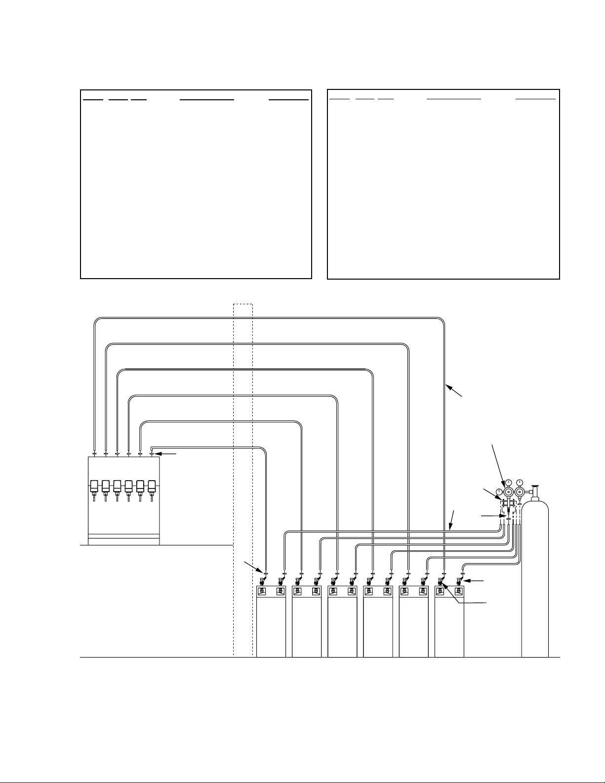
1.1 The accompanying diagram (see next page) demonstrates a typical installation for a six (6) valve
premix dispenser using six (6) figals. Five (5) valve kits use similar plumbing with one (1) less figal
tank.
1.2 It is VERY IMPORTANT to make sure that the Regulator adjustment screws are threaded completely
out before installation. This ensures that CO2 gas does not pass uncontrolled through the
Regulator assembly during connection.
NOTES:
If it is preferred that a Diet product be regulated at a lower CO2 pressure than non-diet products,
ensure that the diet product is connected to the regulator with a single connection. This will allow
Page 3
ii
the diet product to be controlled individually from the other figals.
Item Part No. Description Quantity
-- 82-1264-06 Kit, Installation,
6 Valve, Premix,
US
1 18-0266-01/01 Regulator Assy, 1
Tank Mount, US
2 05-0011 Flare Seal, 1/4 Inch 1
3 01-0221 Stem, 1/4 Inch 1
4 01-0222 Nut, Swivel, 1/4 Inch 1
5 07-0437 Clamp, 1/4 Inch 24
6 08-0349 Tubing, 1/4 Inch AR
7 17-0017 Disconnect, Gas, 6
1/4 Inch
8 17-0018 Disconnect, Liquid, 6
1/4 Inch
Item Part No. Description Quantity
-- 82-1265-06 Kit, Installation,
6 Valve, Premix,
Metric
1 18-0267-01/01 Regulator Assy, 1
Tank Mount, Metric
2 05-0011 Flare Seal, 1/4 Inch 1
3 01-0221 Stem, 1/4 Inch 1
4 01-0222 Nut, Swivel, 1/4 Inch 1
5 07-0437 Clamp, 1/4 Inch 24
6 08-0349 Tubing, 1/4 Inch AR
7 17-0017 Disconnect, Gas, 6
1/4 Inch
8 17-0018 Disconnect, Liquid, 6
1/4 Inch
KIT INSTALLATION, 6 VALVE, PREMIX, FIGAL (CONTINUED)
Typical Installation, Six (6) Valve Pre-Mix Dispenser Using Six (6) Figal Containers
6
1
5
5
6
2,3,4
5
7
8
CO
2
Page 4

1. INSTALLATION
1.1 RECEIVING
Each unit is completed tested under operating conditions and thoroughly inspected before shipment.
At the time of shipment, the carrier accepts the unit and any claim for damages must be made with
the carrier. Upon receiving unit from the delivering carrier, carefully inspect carton for visible
indication of damage. If damage exists, have carrier note same on bill of lading and file a claim with
the carrier.
1.2 UNPACKING
A. Cut band and remove.
B. Remove top portion of carton by lifting up.
C. Remove top inner carton pad and corners.
D. Remove accessory kit of loose parts from drip tray.
E. Lift Unit up by plywood shipping base and remove lower portion of carton.
F. Inspect unit for concealed damage. If evident, notify delivering carrier. File claim against same.
G. Remove splash plate, located under unit on shipping base.
H. Remove plywood shipping base from unit by moving unit so that one side is off the counter top
or table allowing access to screws on the bottom of the plywood shipping base.
NOTE
If unit is to be transported, it is advisable to leave unit secured to plywood shipping base.
I. If Unit is to be installed with optional legs, assemble legs to unit by tilting unit. DO NOT LAY
UNIT ON ITS SIDE OR BACK.
J. Remove accessory kit of loose parts from drip tray.
1.3 SELECTING A COUNTER LOCATION
A. The dispenser is designed to sit on a flat supported surface capable of supporting a minimum
weight of 250 pounds (113.6 kg). It may be either counter or leg mounted.
NOTE
NSF listed units must be sealed to the counter or have four (4) inch legs installed.
B. When the dispenser is to be permanently bolted to the counter top, seal dispenser base to
counter top with a bead of clear silicone caulk or sealant which provides a smooth and easily
cleaned bond to the counter.
CAUTION
FAILURE TO MAINTAIN PROPER AIR CLEARANCE WILL CAUSE THE COMPRESSOR TO
OVERHEAT AND WILL RESULT IN COMPRESSOR FAILURE.
c. Locate dispenser to allow approximately eight (8) inches of unobstructed space above the unit
for proper air circulation. Air is drawn in through the top front grill and exhausted out of the top
rear grill. The bonnet may be removed by lifting bonnet upward.
1.4 CONNECTING THE DRAIN
A. Remove cup rest. Lift splash plate up and pull out and down on the bottom to remove.
B. Remove the drip tray from the unit and connect the drain tube to the drain fitting located on the
bottom. Secure drain tube with clamp provided in accessory kit.
C. Route the drain tube to a suitable drain and replace the unit’s drip tray.
1.5 FILLING UNIT WITH WATER
A. Remove the bonnet from the unit.
B. Remove the yellow plastic plug from the unit’s fill hole.
CAUTION
THE WATER BATH COMPARTMENT MUST BE FILLED WITH WATER BEFORE PLUGGING
IN THE UNIT, OTHERWISE THE COMPRESSOR DECK AND CONDENSER FAN MAY NOT
OPERATE PROPERLY.
C. Fill the water bath compartment with water until it flows out of the overflow tube into the drip tray.
1
Page 5

Use bottled drinking water where hard water problems exist. Do not use distilled water in
units which are equipped with electronic ice bank controls (EIBC).
D. Replace the yellow plug.
1.6 CONNECTING TO ELECTRICAL POWER
WARNING
THIS UNIT MUST BE PROPERLY ELECTRICALLY GROUNDED TO AVOID POSSIBLE FATAL
ELECTRICAL SHOCK OR SERIOUS INJURY TO THE OPERATOR. THE POWER CORD IS
PROVIDED WITH A THREE PRONG GROUNDED PLUG. IF A THREE-HOLE GROUNDED
ELECTRICAL OUTLET IS NOT AVAILABLE, USE AN APPROVED METHOD TO GROUND THE
UNIT.
CAUTION
FAILURE TO DISCONNECT THE MOTOR POWER SUPPLY WILL DAMAGE THE CARBONATOR
MOTOR AND PUMP AND VOID THE WARRANTY.
A. Check the dispenser serial number plate for unit’s correct electrical requirements. Do not plug
into electrical outlet unless serial number plate electrical specifications are compatible with local
electric utility.
B. Route the power supply cord to a grounded electrical outlet of the proper voltage and amperage
rating, and plug the unit in. All USA/domestic models are equipped with a power kill switch
located on the left side of the condenser, in the bonnet. Kill switch must be on before the unit
will operate. Allow unit to run and start cooling while completing remainder of the installation.
NOTE
Units equipped with an electronic ice bank control contain a five (5) minute delay. Compressor
will not begin running until five (5) minutes after unit is energized.
1.7 CONNECTING TO PRODUCT SUPPLY (see Page ii)
A. Using proper beverage tubing and fittings, connect to product inlet with a clamp (PN 07-0437).
B. Mark syrup tube assemblies with product ID tape.
C. Route through cutout in counter or through access hole in back of unit.
D. Leave approximately 12 inches (300 mm) of extra tubing length below the counter for servicing
and moving the dispenser.
E. Connect to appropriate figal pre-mix tanks using clamps to secure the connection.
F. Pressurize system.
G. Activate each valve until product is observed.
H. Check for leaks.
2. SCHEDULED MAINTENANCE
2.1 DAILY
A. Remove the cup rest and wash in warm soapy water.
B. Pour warm soapy water into the drip tray and wipe with a clean cloth.
C. With a clean cloth and warm water, wipe off all of the unit’s exterior surfaces. DO NOT USE
ABRASIVE SOAPS OR STRONG DETERGENTS.
D. Replace the cup rest.
2.2 WEEKLY
A. Taste each product for off tastes.
B. Remove the bonnet and check the level of water in the water bath. Replenish as required, and
replace the bonnet.
NOTE
Use bottled drinking water where hard water problems exist. Do not use distilled water in units
which are equipped with electronic ice bank controls (EIBC).
2.3 MONTHLY
A. Unplug the dispenser from power source.
2
Page 6

B. Remove the bonnet and clean the dirt from the condenser using a soft brush.
C. Replace the bonnet and reconnect power.
2.4 EVERY SIX MONTHS
A. Clean and sanitize the unit using the appropriate procedures outlined in Section 3 of this
manual.
2.5 YEARLY
A. Clean water bath interior, including evaporator coils and refrigeration components.
B. Clean the entire exterior of the unit.
C. Sanitize syrup lines using the appropriate procedures outlined in Section 3 of this manual.
3. DISPENSER CLEANING AND SANITIZING
3.1 AMBIENT PROCESS
A. The ambient process is the most common method for cleaning and sanitizing dispenser
equipment. The detergent should be caustic-based and the sanitizer should be low pH (7.0)
chloride solution.
B. Disconnect syrup containers and remove product from tubing by purging with carbon dioxide.
C. Rinse the lines and fittings with clean room temperature water to remove all traces of residual
product.
D. Fill lines with a caustic-based (low-sudsing, non-perfumed, and easily rinsed) detergent solution.
The solution should be prepared in accordance with the manufacturers recommendations, but
should be at least two (2) percent sodium hydroxide. Make sure the lines are completely filled
and allow to stand for at least 10 minutes.
E. Flush the detergent solution from the lines with clean water. Continue rinsing until
phenolphthalein test indicates the rinse water is free of residual detergent.
F. Fill the lines with a low pH (7.0) chlorine solution containing at least 50 PPM (50 mg/L) chlorine.
Make sure that lines are completely filled and allow to stand for ten (10) minutes.
G. Reconnect syrup containers and ready Unit for operation.
H. Draw drinks to refill lines and flush the chlorine solution from the dispenser.
NOTE
Please note that a fresh water rinse cannot follow sanitization of equipment. Purge only with the
end use product. This is an NSF requirement.
I. Taste the beverage to verify that there is no off taste.
3.2 VALVES
A. Valves may be cleaned and sanitized in the same manner.
1. Disconnect Unit from power source. Depressurize unit, disconnect syrup containers, and
remove product from tubing by purging with carbon dioxide.
2. Carefully remove valves from dispenser.
3. Wash valves in cleaning solution, then immerse them in a bath of sanitizing solution for
15 minutes.
4. Visually inspect dispenser for syrup residue. Clean with warm water and cloth or with the
nozzle brush supplied.
5. Install valves to dispenser. Pressurize and ready Unit for operation.
6. Connect Unit to power source.
7. Reconnect syrup containers and ready Unit for operation.
8. Draw drinks to refill lines and flush the chlorine solution from the dispenser.
NOTE
Please note that a fresh water rinse cannot follow sanitization of equipment. Purge only with
the end use product. This is an NSF requirement.
9. Taste the beverage to verify that there is no off taste.
10. Valve is ready for operation.
3
Page 7

4. TROUBLESHOOTING
TROUBLE CAUSE REMEDY
4.1 Miscellaneous leakage. A. Gap between parts. A. Tighten appropriately.
B. Damaged or improperly B. Replace or adjust appropriate
installed o-rings. o-rings.
4.2 Insufficient flow. A. Insufficient incoming supply A. Verify incoming supply pressure
pressure. is correct.
4.3 Excessive foaming. A. Incoming product A. Correct prior to dispenser.
temperature too high. Consider larger dispenser or
pre-cooler.
B. Flow rate too high. B. Readjust.
C. Air in lines. C. Bleed air from lines.
D. Poor quality ice. D. Check quality of ice used in drink.
E. High beverage temperature. E. Check refrigeration system.
4.4 Compressor does not A. Compressor relay or overload A. Replace compressor relay or
start (no hum), but malfunctioning. overload.
condenser fan motor B. Inadequate voltage. B. Measure voltage across common
runs. and run terminal on compressor.
Voltage must not drop below 90%
of rated voltage.
C. Incorrect wiring. C. Refer to wiring diagram and correct.
D. Compressor malfunctioning. D. Replace compressor.
4.5 Compressor starts and A. Ice bank control failure. A. Replace ice bank control.
continues to run until B. Incorrect wiring. B. Refer to wiring diagram and correct.
freeze up and will not
cut off.
4.6 Compressor does not A. Inadequate voltage. A. Measure voltage across common
start but hums. and run terminal on compressor.
Voltage must not drop below 90%
of rated voltage.
B. Incorrect wiring. B. Refer to wiring diagram and correct.
C. Starting relay malfunctioning. C. Replace starting relay. Be sure to
use correct relay. Failure to use
correct relay will cause compressor
failure.
D. Compressor malfunctioning. D. Replace compressor.
4.7 Compressor starts but A. Inadequate voltage. A. Measure voltage across common
does not switch off start and run terminal on compressor.
winding (will run for only B. Incorrect wiring. B. Refer to wiring diagram and correct.
a few seconds before C. Starting relay malfunctioning. C. Replace starting relay. Be sure to
internal overload use correct relay. Failure to use
switches compressor correct relay will cause compressor
off). failure.
4.8 Compressor starts and A. Dirty condenser. A. Clean the condenser.
runs a short time but B. Insufficient or blocked air flow. B. Remove all obstructions and allow
shuts off on overload. for minimum clearance of
15 inches (38.1 cm) over top.
C. Inadequate voltage. C. Measure voltage across common
and run terminal on compressor.
Voltage must not drop below 90%
of rated voltage.
D. Incorrect wiring. D. Refer to wiring diagram and correct.
E. Defective condenser fan motor. E. Replace condenser fan motor.
F. Refrigerant leak. F. Repair and recharge.
G. Compressor malfunctioning. G. Replace compressor.
(continued next page)
4
Page 8

5
(continued from previous page)
4.9 Warm drinks. A. Restricted airflow. A. Check clearances around sides,
top, and inlet of unit. Remove
objects blocking airflow through
grill.
B. Refrigeration system not B. Refer to Sections 4.11 - 4.15.
running.
C. Refrigerant leak. C. Repair and recharge.
D. Condenser fan motor not D. Replace condenser fan motor.
working.
E. Dirty condenser. E. Clean condenser.
F. Dispenser capacity exceeded. F. Add pre-cooler or replace with
larger dispenser.
NOTES
TROUBLE CAUSE REMEDY
Page 9

6
NOTES
Page 10

LOAD
LINE
FROM
EVAPORATOR
5. ILLUSTRATIONS, PARTS LISTS, AND WIRING DIAGRAMS
5.1 REFRIGERATION DECK ASSEMBLY
7
12
11
29
20
30
26
20E
20A
20C
20D
20B
27
44
12
16
FROM
EVAPORATOR
20F
23
10
28
41
42
22
43
48
15
8
18
1
5
45
9
LINE
LOAD
17B
17A
17C
17F
7
17E
17D
17G
6
17
2
21
13
40
40A
40B
12
19
3
39A
39G
4
39
39E
39B
39C
3
39F
39D
40C
12
38
12
37
31
32
24
25
35
36
33
34
32
34
33
Page 11

5.1 REFRIGERATION DECK ASSEMBLY (CONTINUED)
ITEM PART NO. DESCRIPTION
- 82-2768 Deck Assy, Refrigeration,
115V/60Hz, Non-Carb
- 82-2901 Deck Assy, Refrigeration,
230V/50Hz, Non-Carb
- 82-2902 Deck Assy, Refrigeration,
220V/60Hz, Non-Carb
1 51-5496 Deck Plate, Sub-Assy
2 50-0200/01 Insulation, Deck Plate
3 04-0063 Washer, Flat, 1/4”
4 89-0014 Hole Cover
5 82-2494 Evaporator Assy
6 52-1773 Probe Assy
7 04-0394 Screw, 6 - 32 X .500”
8 51-0068 Handle
9 04-0574 Washer, Lock, 5/16”
10 REF Control Housing Assy
- 52-0900/02 Control Housing Assy
with Kill Switch
- 52-0903/02 Control Housing Assy
without Kill Switch
11 06-2221 Label, Wiring Diagram
12 04-0504 Screw, 8 - 18 X .375”
13 06-0080/01 Label, Nameplate
14 - - - - - - - (This item not used.)
15 02-0041 Seal
16 25-0047 Transformer, 75VA, 24V,
115V/60Hz
- 25-0048 Transformer, 75VA, 24V,
220V/50-60Hz
17 82-2558 Agitator Assy, 115V/60Hz
- 82-2487 Agitator Assy, 230V/50Hz
- 82-2761 Agitator Assy, 220V/60Hz
17a 05-0424/01 Propeller, 2.625” Diameter
17b 91-0119 Motor, Agitator, 115V/60Hz
- 91-0112 Motor, Agitator, 230V/50Hz
- 91-0130 Motor, Agitator, 220V/60Hz
17c 06-0633 Label, 115V/60Hz, 25W
- 06-0634 Label, 230V/50Hz, 25W
- 06-2191 Label, 220V/60Hz, 25W
17d 04-0059 Screw, 8 - 36 X .375”
17e 30-5113/01 Bracket, Agitator Motor
17f 02-0032 Washer, Rubber
17g 05-1437 Propeller, Water
18 02-0040 Seal, Extrusion
19 04-0032 Nut, Lock, 1/4” - 20
20 83-0033 Compressor Assy, 1/3 hp,
115V/60Hz (includes items
listed below)
- 83-0034 Compressor Assy, 1/3 hp,
240-220V/50Hz
- 83-0038 Compressor Assy, 1/3 hp,
220V/60Hz
20a 83-0033-01 Compressor, 1/3 hp,
115V/60Hz
- 83-0034-01 Compressor, 1/3 hp,
240-220V/50Hz
20b 04-1010 Screw, Brass, 6 - 32 X 0.250”
20c 12-0339 Overload, 115V/60Hz
- 12-0290 Overload, 230V/50Hz
- 12-0253 Overload, 220V/60Hz
20d 12-0005 Relay, 115V/60Hz
- 12-0031 Relay, 230V/50Hz
- 12-0028 Relay, 220V/60Hz
20e 13-0066 Cover, Terminal
20f 03-0040 Bale Strap
20g 03-0041 Spring Overload (Not Shown)
20h 12-0260 Start Capacitor, 220V/60Hz
(Not Shown)
ITEM PART NO. DESCRIPTION
8
21 02-0114 Grommet, Compressor
22 04-0537 Washer, Compressor
23 03-0150 Clip, Retainer, Compressor
24 47-0344 Tube, Process
25 47-0718 Tube, Compressor Discharge
26 47-0724 Tube, Return Line
27 51-0061 Accumulator
28 50-0211 Boot
29 50-0205 Insulation
30 50-0159 Insulation
31 23-0985 Condenser
32 50-0201 Baffle, Rubber
33 30-5112 Retainer Strip
34 04-0518 Rivet, 0.125" X 0.328"
35 30-5867 Handle/Air Shield
36 51-5697 Fan Shroud, Upper
37 50-0249 Insulation, Strip
38 30-5866 Fan Shroud, Lower
39 52-2140 Fan Assy, 115V/60Hz
- 52-2147 Fan Assy, 220V/50-60Hz
39a 91-0007 Motor Assy, 115V/60Hz, 9W
- 91-0009 Motor Assy, 220V/50-60Hz, 9W
39b 07-0354 Fan Blade
39c 04-0060 Nut, Flat
39d 30-5864 Bracket, Fan Motor
39e 02-0033 Silencer, Fan Blade
39f 04-0059 Screw, 8 - 36 X 0.375"
39g 06-0433/01 Label, 115V/60Hz, 9W
- 06-0670 Label, 220V/50-60Hz, 9W
40 23-0765 Dryer Cap Assy
40a 23-0982 Dryer Cap
40b 47-0344 Tube, Process
40c 47-0698 Tube, Condenser, Out
41 52-2008 Harness Assembly, Transformer
42 04-0110 Nut, 8-32
43 04-0576 Washer, Lock, Internal Tooth
44 06-0430 Label, 115V/60 Hz, 1/3 HP
- 06-0460 Label, 230V/50 Hz, 1/3 HP
- 06-0666 Label, 240V/60 Hz, 1/3 HP
45 06-0877 Label, Ground
- 11-0018 Wire Tie
- 15-0012 Duct Tape
- 15-0011 Adhesive, Insulation
- 95-0177 Refrigerant, R-134a
- 96-0004 Solder, 60/40
- 96-0003 Brazing Alloy
- 52-2027 Harness Assy, PCB to Ground
Page 12

5.2 DECK ASSEMBLY
9
5
3
4
1
W
A
TE
FILL W
R
-IM
W
B
AT
A
T
PO
TH
AN
A
ER
TE
R
FILL H
K
T
F
O
R
AN
LO
B
VE
T
AT
W
-
R
O
S FR
H
FLO
LE
U
N
W
O
TIL
M
T
U
BE
.
2
6
Page 13

ITEM PART NO. DESCRIPTION
1 04-0711 Caplug
2 06-0856 Label, Water Fill
3 04-0431 Screw, 1/4 - 20 x 1.250,
Round Head
4 04-0033 Washer, 1/4
5 30-5891/01 Plate, Carbonator
(No Carbonator)
6 50-0254/01 Insulation, Carbonator Deck
(No Carbonator)
5.2 DECK ASSEMBLY (CONTINUED)
10
Page 14

5.3 CABINET ASSEMBLY
11
28
29
30
25
26
REF
12
11
REF
REF
33
27
REF
3
4
REF
7
32
1
2
5
14
8
5
15
10
9
6
16
17
21
22
25
24
31
5
23
20
13
19
18
5
5
18
19
Page 15

ITEM PART NO. DESCRIPTION
- 82-2551 Cabinet Assy
1 51-5629/01 Wrapper Assy
2 30-7353/01 Front Support, SS
3 04-0443 Screw, 10 - 24 x 0.375”,
Countersink
4 04-0074 Nut, Clip, 10 - 24
5 04-0504 Screw, 8 - 18 x 0.375”, with
Washer
6 08-0004 Tubing, Tygon, 5/16” ID
7 06-0851 Label, Overflow
8 03-0302 Clip, Drain Hose
9 04-0077 Screw, 4 - 20 x 0.250”
10 03-0062 Clip, Overflow Tube
11 30-0319 Splash Plate
12 05-1585 Cup Rest, Plastic
13 05-1657 Drip Tray
14 30-7533/01 Bracket, Drip Tray, Right
15 30-7534/01 Bracket, Drip Tray, Left
16 04-0545 Screw, 8 - 16 x 0.750”
17 30-7358 Plate, Tank, Bottom
18 51-0717/01 Bracket, Leg
19 81-0112 Leg, Plastic
20 07-0405 Plug, Key Switch
21 12-0097 Key Switch (Includes Nut)
22 06-0881 Label, Key Switch
23 07-0347 Plate, Cover
24 REF Tank Assy
- 42-0057 Tank Assy
- 42-0058 Tank Assy, LF Sol
25 50-0151 Insulation, Tank, Side
26 50-0150 Insulation, Tank, Back
27 50-0248 Insulation, Tank, Front
28 06-0632 Label, "WARNING"
29 REF Bonnet Assy
- 82-2764 Bonnet Assy
(Contact Customer Service
for Graphic Options)
30 06-2177 Label, Graphic, Bonnet
(Contact Customer Service
for Graphic Options)
31 06-2178 Label, Graphic, Tank Wrapper
(Contact Customer Service for
Graphic Options)
32 06-2227 Decal, Bonnet, Front
(Contact Customer Service
for Graphic Options)
33 50-0209 Insulation, Comb
REF REF See Section 5.4
5.3 CABINET ASSEMBLY (CONTINUED)
12
Page 16

5.4 TUBING ASSEMBLY
13
14
13
10
8
9
7
12
11
15
4
6
5
3
2
1
Page 17

ITEM PART NO. DESCRIPTION
R1 19-0258 Valve Assy, Pre-Mix, Becker
2 30-5486 Faucet Plate, 5 Valve
- 30-5488 Faucet Plate, 6 Valve
3 30-5487 Support, Faucet Plate, 5 Valve
- 30-5489 Support, Faucet Plate, 6 Valve
4 REF Backing Nut, Valve
5 48-0760 Tube Assy, Prod #4/3, 6V/5V
6 48-0759 Tube Assy, Prod #5/4/3, 6V/5V
7 48-0761 Tube Assy, Prod #3, 6V
8 48-0762 Tube Assy, Prod #2, Pre-Delta
9 48-1494 Tube Assy, #1, Pre-Mix
10 48-1495 Tube Assy, #6, Pre-Mix
11 01-1831 Spacer, 10 - 24, Threaded
12 30-6807 Spacer. Lower, Water Cage
13 30-6767 Brace, Water Coils
14 04-0116 Screw, 10 - 24 x 0.625,
PHD, PH, SS
R1 05-1932 Fitting, Adapter,
7/16 MF x 1/2 MF
R in margin indicates change or revision
5.4 TUBING ASSEMBLY (CONTINUED)
14
Page 18

1/2 A
(SPARE)
F2
2AG
HS1
HYBRID MODULE
C2
RLY2
U1
VR1
J1
_
1
BR1
1
J2
1
J3
RLY1
1
NO TIME
C5
R1
C4
J5
MADE IN U.S.A.
J4
5.5 CONTROL HOUSING
15
10
9
8
7
6
11
5
4
3
2
1
20
12
12
19
13
14
15
16
17
18
Page 19

ITEM PART NO. DESCRIPTION
- 52-0900/02 Control Housing, With
ON/OFF Switch
R - 52-0903/02 Control Housing, Without
ON/OFF Switch
1 30-5109/02 Control Housing
2 52-0868/01 Lead Assy,
ON/OFF Switch
3 13-0047 Stand-off
4 52-1423/01 PCB Assy
5 52-2027 Lead Assy, Probe Ground
(Non-Carb Units Only)
6 52-2061 Lead Assy, EIBC
7 12-0190 Terminal Block
8 04-0477 Screw, 8 - 32 x 0.375"
9 04-0504 Screw, 8 - 16 x 0.375"
10 30-5108/01 Cover, Control Box
11 11-0186 Jumper, 4-Position
12 13-0059 Bushing
13 13-0028 Strain Relief
14 52-1219 Power Cord (Pigtail)
15 52-0904 Harness Assy, Trans #1
16 52-0905 Harness Assy, Trans #2
17 52-0906 Harness Assy, Comp #1
18 52-0907 Harness Assy, Comp #2
19 11-0008 Tie Wrap
20 12-0089 Switch
R in margin indicates change or revision
5.5 CONTROL HOUSING (CONTINUED)
16
Page 20

17
5.6 WIRING DIAGRAM
IMPORTANT
8
16
15714
PLAIN
BLK
AGITATOR
MOTOR
B
W
TB1
B/WB/W
65
TO PLAIN WATER VALVE
(FIELD INSTALLED OPTION)
BRG
W
BRG
J1
TERM4
13
W
IN
J2
PCB,IBC
OUT
TERM3
B
B
12411
W
3
3
G
GW B
IN
TERM2
B
1
J3
2
10 9
J4
OUT
TERM1
BB
1
W
RIBBED
9000 and 9100 Series Only
BWG
CARBONATOR
PROBE
B
G
B/W
B
COMPRESSOR
9000 and 9100 Series Only
B
B
BLK
B
CARBONATOR
MOTOR
CAPACITOR
WBWB
1 4
B
WBW
FAN
MOTOR
W
R
G
1. WHEN STARTING UNIT OR IF CURRENT IS INTERRUPTED, THERE IS A FIVE (5) MINUTE
DELAY BEFORE THE COMPRESSOR/FAN STARTS.
2. THERE IS A THREE (3) MINUTE PROTECTION TIMER ON THE CARBONATOR PUMP MOTOR.
IF THE MOTOR HAS TIMED OUT, CHECK WATER SUPPLY AND RESET BY MOMENTARILY
DISCONNECTING POWER.
9000 and 9500 Series Only
W
KEY
SWITCH
ELECTRONIC
ICE BANK
LINE
24 V
B
B
PROBE
RIBBED
BLK
V
A
L
V
E
S
(5,
OR
6)
S1
B
S2
B
S3
B
S4
B
S5
B
S6
OPTIONAL
MARQUEE
POWER
CORD
B
BLU BRNG
B
W
W
W
W
W
W
KILL
SWITCH
DELTA
RECIRCULATING MOTOR
9100 SERIES ONLY
SYM.
DESCRIPTION
CHASSIS GROUND
CHAMFER PIN
OPTIONAL WATER
BOOST PCB,IBC J4
CONTROL BOX
CARBONATOR
MOTOR
®
LABEL, WIRING DIAGRAM
06-2221
 Loading...