

Page 1
DELTA III DISPENSER SERIES 9000
Operation Manual
PN: 28-0437/05
9000
Lancer Corp.
6655 Lancer Blvd.
San Antonio, Texas 78219
800-729-1500
Technical Support/Warranty: 800-729-1550
custserv@lancercorp.com
lancercorp.com
Manual PN: 28-0437/05
SEPTEMBER 2011
FOR QUALIFIED INSTALLER ONLY
“Lancer” is the registered trademark of Lancer © 2014 by Lancer, all rights reserved.
Page 2

ABOUT THIS MANUAL
This booklet is an integral and essential part of the product and should be handed over to the operator after the
installation and preserved for any further consultation that may be necessary. Please read carefully the guidelines and
warnings contained herein as they are intended to provide the user with essential information for the continued safe
use and maintenance of the product. In addition, it provides GUIDANCE ONLY to the user on the correct services and
site location of the unit.
The installation and relocation, if necessary, of this product must be carried out by qualied personnel with up-to-date
safety and hygiene knowledge and practical experience, in accordance with current regulations.
TABLE OF CONTENTS
SPECIFICATIONS................................................................................................................................4
PRE-INTALLATION CHECKLIST........................................................................................................5
WARNINGS/CAUTIONS...................................................................................................................6-9
1. INSTALLATION...........................................................................................................................10
1.1 UNPACKING.......................................................................................................................10
1.2 UNPACKING INSTALLATION KITS....................................................................................10
1.3 SELECTING A COUNTER LOCATION...............................................................................10
1.4 INSTALLING DISPENSER..................................................................................................10
1.5 LEVELING DISPENSER.....................................................................................................10
1.6 CONNECTING THE DRAIN................................................................................................10
1.7 FILLING UNIT WITH WATER..............................................................................................11
1.8 CONNECTING TO ELECTRICAL POWER........................................................................11
1.9 CONNECTING TO WATER SUPPLY - CARBONATED WATER INLET.............................12
1.10 CONNECTING TO WATER SUPPLY - PLAIN WATER INLET............................................12
1.11 CONNECTING THE CO2 SUPPLY.....................................................................................12
1.12 CONNECTING BAG-IN-BOX (BIB) SYRUP SUPPLY TO UNITS WITH BUILT-IN
SYRUP PUMPS..................................................................................................................13
1.13 CONNECTING BAG-IN-BOX (BIB) SYRUP SUPPLY TO UNITS TO REMOTE
SYRUP PUMPS..................................................................................................................13
1.14 CONNECTING TO REMOTE PRESSURIZED SYRUP SUPPLY (FIGAL).........................13
1.15 PURGING THE CARBONATION SYSTEM........................................................................13
1.16 PURGING THE WATER AND SYRUP SYSTEMS..............................................................14
1.17 ADJUSTING WATER FLOW (LEV®)..................................................................................14
1.18 ADJUSTING WATER TO SYRUP (RATIO) BRIX (LEV®)..................................................14
1.19 VOLUMETRIC VALVE ADJUSTMENT...........................................................................14-16
1.20 SETTING 3-WAY ADJUSTABLE BACK BLOCKS FOR PLAIN OR
CARBONATED WATER......................................................................................................16
2. CLEANING AND SANITIZING....................................................................................................17
2.1 GENERAL INFORMATION..................................................................................................17
2.2 CLEANING SOLUTION......................................................................................................17
2.3 SANITIZING SOLUTION.....................................................................................................17
2.4 SCHEDULED MAINTENANCE...........................................................................................18
2.5 AMBIENT PROCESS (SYRUP LINE CLEANING).............................................................18
2.6 VALVE CLEANING........................................................................................................19-20
2.7 CLEANING AND SANITIZING BAG-IN-BOX (BIB) SYSTEMS...........................................21
2.8 CLEANING AND SANITIZING FIGAL SYSTEMS.........................................................21-22
3. CONVERTING FROM EXTERNAL PRESSURIZED SYRUP SUPPLY TO BIB WITH BUILT-IN
SYRUP PUMPS...........................................................................................................................22
2
Page 3

4. CONVERTING FROM BUILT-IN SYRUP PUMPT TO REMOTE PUMPS OR
SYRUP TANKS............................................................................................................................23
4.1 REMOVING EXISTING BUILT-IN SYRUP PUMPS............................................................23
4.2 INSTALLING REMOTE PUMP OR SYRUP TANKS............................................................23
5. TROUBLESHOOTING...........................................................................................................24-31
6. TROUBLESHOOTING THE LANCER ELECTRONIC ICE BANK CONTROL (EIBC)...............32
6.1 CHECKING FOR NORMAL PCB OPERATION..................................................................32
7. ILLUSTRATIONS, PARTS LISTINGS, WIRING DIAGRAMS, AND
PLUMBING DIAGRAMS.............................................................................................................34
7.1 REFRIGERATION DECK ASSEMBLY...........................................................................34-35
7.2 STANDARD CABINET ASSEMBLY...............................................................................36-37
7.3 SHROUDED CABINET ASSEMBLY..............................................................................38-39
7.4 CARBONATOR, WATER/SYRUP LINE ASSEMBLIES.................................................40-41
7.5 CARBONATOR DECK/PUMP BRACKET ASSEMBLIES..............................................42-43
7.6 CONTROL HOUSING.........................................................................................................44
7.7 WATER REGULATOR ASSEMBLY.....................................................................................45
7.8 WIRING DIAGRAM.............................................................................................................46
8. DISPENSER DISPOSAL.............................................................................................................47
3
Page 4
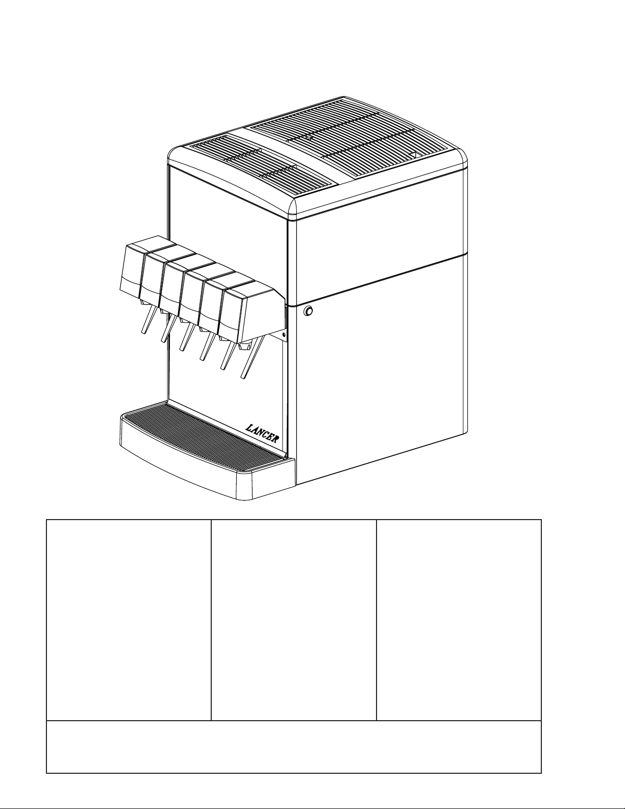
DELTA III SPECIFICATIONS
Æ
DIMENSIONS
Width: 25 9/16 inches (649 mm)
Depth: 25 7/8 inches (657 mm)
Height: 16 7/8 inches (429 mm)
WEIGHT
Empty: 146 pounds (66.2 kg)
Operating: 220 pounds (99.8 kg)
Shipping: 160 lbs (72.5 kg)
PLAIN WATER SUPPLY
Min owing pressure: 20 PSI
(0.138 MPA)
Soda Water: Per carbonator
manufacturer recommendations.
SPACE REQUIRED
Left Side: 4 inches (101.6 mm)
Right side: 4 inches (101.6 mm)
Top: 8 inches (203.2 mm)
Optional legs: 4 inches (101.6
mm)
ICE
Capacity: 25 - 28 pounds
(11.3 to 12.7 kg)
FITTINGS
Water for carbonator inlet:
CARBON DIOXIDE (CO2)
Min pressure: 70 PSIG
(0.483 MPA)
Max pressure: 80 PSIG
(0.552 MPA)
3/8 in barb
ELECTRICAL
115VAC/60Hz/3 amps
220-230VAC/50-60Hz/1.5 amps
Plain water inlet: 3/8 in barb
Brand syrup inlets: 3/8 in barb
CO2 inlet: 3/8 in barb
DRINK CAPACITY CONDITION C CONDITION D
(90°F (32°C), 65%RH) (105°F (41°C), 75%RH)
2-12 ounce drinks below 40°F (4.4°C) 125 drinks 115 drinks
4-12 ounce drinks below 40°F (4.4°C) 97 drinks 92 drinks
4
Page 5
PRE-INSTALLATION CHECKLIST
BEFORE GETTING STARTED
Each unit is tested under operating conditions and is thoroughly inspected before
shipment. At the time of shipment, the carrier accepts responsibility for the unit. Upon
receiving the unit, carefully inspect the carton for visible damage. If damage exists, have
the carrier note the damage on the freight bill and le a claim with carrier. Responsibility for
damage to the dispenser lies with the carrier.
TOOLS REQUIRED
Oetiker Pliers Slotted Screwdriver
Tubing Cutters Phillips Screwdriver
Wrench Cordless Drill
POST MIX ACCESSORIES
CO2 Regulator Set CO2 Supply
Beverage Tubing Oetiker Clamps/Fittings
Water Booster Water Regulator
Precision Cutters (if removing/replacing carbonator tank)
BIB SYSTEM
BIB Rack BIB Regulator Set
BIB Syrup Boxes
BIB Connectors - ensure you have the correct connectors for syrup lineup.
CONSIDER LOCATION OF THE FOLLOWING PRIOR TO INSTALL
Water supply lines Drain
Is the countertop level? Heating and air conditioning ducts
Grounded electrical outlet.
Enough space to install the dispenser. Include space for a top-mounted ice machine, if necessary.
Does the top-mounted ice machine have a minimum clearance on all sides?
Located away from direct sunlight or overhead lighting.
Can the countertop support the weight of the dispenser? Be sure to include the weight of an ice
machine (if necessary) plus the weight of the ice.
This unit is not suitable for use in an area where a water jet could be used.
5
Page 6

! !
WARNING/ADVERTENCIA/AVERTISSEMENT
! The dispenser is for indoor use only. This appliance is intended for use in commercial applications such as
restaurants, stores or similar. This unit is not a toy. It should not be used by children or inrm persons without
supervision. This appliance is not intended for use by persons (including children) with reduced physical, sensory
or mental capabilities, or lack of experience and knowledge, unless they have been given supervision or instruction
concerning use of the appliance by a person responsible for their safety. Cleaning and user maintenance shall not
be performed by children without supervision. This unit is not designed to dispense dairy products. The minimum/
maximum ambient operating temperature for the dispenser is 40°F to 105°F (4°C to 41°C). Do not operate unit below
minimum ambient operation conditions. Should freezing occur, cease operation of the unit and contact aurthorized
service technician. Service, cleaning and sanitizing should be accomplished only by trained personnel. Applicable
safety precautions must be observed. Instruction warnings on the product being used must be followed.
! El dispensador sólo debe usarse en interiores. Esta unidad está diseñada para su uso en aplicaciones
comerciales tales como restaurantes, tienda o similares. Esta unidad no es un juguete. No la deben usar niños ni
personas discapacitadas sin supervisión. Esta unidad no está destinada al uso por parte de personas (incluso niños)
con capacidad física, sensorial o mental reducida, o sin experiencia y conocimientos sucientes, a menos que una
persona responsable de su seguridad les haya dado supervisión o capacitación en el uso de la unidad. Limpieza y
mantenimiento de usuario no deberá ser realizada por los niños sin supervisión. Esta unidad no ha sido diseñada
para suministrar productos lácteos. La temperatura ambiente operativa mínima / máxima para el dispensador es de
40°F a 105°F (4°C a 41°C). No opere la unidad por debajo de las condiciones mínimas de funcionamiento ambiente.
En caso de ocurrir congelación, cesar la operación de la unidad y póngase en contacto con el servicio técnico
autorizado. Servicio de limpieza y desinfección debe llevarse a cabo solamente por personal especializado.
Precauciones de seguridad aplicables deben ser observadas. Advertencias de instrucciones en el producto que se
use debe ser seguido.
! Le distributeur est destiné à un usage à l’intérieur seulement. Cet appareil est conçu pour une utilisation dans des
applications commerciales telles que les restaurants, les dépanneurs ou similaires. Cet appareil n’est pas un jouet. Il
ne devrait pas être utilisé par des enfants ou des personnes inrmes sans surveillance. Cet appareil n’est pas destiné
à un usage par des personnes (y compris les enfants) ayant des capacités physiques, sensorielles ou mentales
réduites, ou manquant d’expérience et de connaissances, à moins qu’elles obtiennent de la surveillance ou des
instructions au sujet de l’utilisation de l’appareil de la part d’une personne chargée de leur sécurité. Nettoyage et
entretien de l’utilisateur ne doivent pas être effectués par des enfants sans surveillance. Cet appareil n’est pas conçu
pour distribuer des produits laitiers. La température de service ambiante minimum/maximum pour le distributeur est
de 40°F à 105°F (4°C à 41°C). Ne pas faire fonctionner l’appareil ci-dessous les conditions minimales de
fonctionnement ambiantes. Faut-gel se produisent, cesser l’exploitation de l’appareil et contactez technicien agréé.
Service de nettoyage et de désinfection doivent être effectuées uniquement par du personnel qualié. Les mesures
de sécurité applicables doivent être respectées. Avertissements Instruction sur le produit utilisé doit être suivie.
6
Page 7
!
This unit has been factory sanitized per Lancer specications.
Listed below are six critical elements which will aid in a successful installation.
1. Fill water bath until water overows from tank overow tube.
2. The carbonator pump motor must be disconnected from the power supply (see Section 1.7) prior to connection to
water supply for initial build up of ice bank. Failure to do so will result in automatic shut off of carbonator (see item
6 below) or damage to the pump.
3. If this dispenser is installed in an area that is susceptible to ±10% variation of the nominal line voltage, consider
installing a surge protector or similar protection device.
4. There is a ve (5) minute delay which prevents the compressor and condenser fan from starting until the delay
has lapsed. If electrical current is interrupted, there is always a ve (5) minute delay before the compressor starts.
5. Supply Water Pressure: Minimum - 25 PSI (0.172 MPA); Maximum - 50 PSI (0.345 MPA); If pressure is over 50
PSIG (0.345 MPA), a water pressure regulator must be used.
6. On units with the built in water regulator, the regulator must be removed if inlet water pressure is less than 25
PSIG. (0.172 MPA)
DISPENSER INSTALLATION HIGHLIGHTS
!
!
Esta unidad ha sido saneada en fabrica por las especicaciones de Lancer.
A continuacion se relacionan 6 puntos importantes para una connecta instalacion.
1. Llene el bano-Maria hasta que el agua se desborde sobre el tubo que controla la derrama del tanque.
2. El motor de la bomba del carbonatador debe desconectarse electricamente (Ver Manual - Seccion 1.7) antes
de conectar el suministro de agua para la formacion inicial del banco de hielo. De no hacerse esto resultaria en
un bloqueo automatico del carbonatador (ver abajo el punto 6) o en danos a la bomba.
3. Si la unidad va a ser instalada en un area en la que puedan darse variaciones de voltage de + 6 - 10% de su
valor nominal, se debe considerar la conveniencia de instalar un estabilizador de corriente o sistema de
proteccion similar.
4. Hay una demora de 5 minutos que evita que el compresor y el abanico del condensador arranquen hasta pasado
ese tiempo. Si hay algun corte en la corriente electrica siempre se producira esa demora de 5 minutos antes de
arrancar el compresor.
5. Presión de suministro del agua de red: Minimo 25 PSI (0.172 MPA); Maximo 50 PSI (0.345 MPA). En unidades
sin regulador de presión incorporado, si la presión del agua es superior a 50 PSIG (0.345 MPA) se debe usar un
regulador de presión.
6. En unidades con regulador de presión incorporado, el regulador debe der eliminado cuando la presión de entrada
de agua sea inferior a 25 PSIG (0.172 MPA).
REGLES DE SECURITE POUR L’NSTALLATION DU DISTRIBUTEUR DE SODAS
!
PUNTOS IMPORTANTES EN LA UNIDAD DISPENSADORA
!
!
La proprètè da cet ensamable est assurè à I’usine sulvant les spècications èmis par Lancer .
Il est essentiel de respecter les 6 points suivants pour l’installation de l’appareil:
1. Remplir le bain-Maire jusqu’a ce que l’eau dèborde par le tuyau de trop-plein du rèservoir.
2. Le moteur de la pompe du carbonateur doit etre dèbranchè de l’alimentation èlectrique (Voir le manuel,
Section 1.7) avant l’arrivèe de l’eau pour la formation initiale de la glace. Oublier ou nègliger cette opèration
provoquera l’arret automatique du carbonateur (voir le point 6 cidessous) ou causera des dommages à la pompe.
3. Si le distributeur es installè dans une zone ou la tension èlectrique nominale est susceptible de variations de (+)
10%, il est conseillè d’installer un appaeil de protection contre les sautes de courant.
4. Un d’lai de 5 minutes empeche le compresseur et la ventilation du condesateur de se mettre en marche avant
que ce lees de temps ne se soit ècoulè. Lorsque le courant èlectrique es interrompu, il y a toujours un dèlai de 5
minutes avant que le presseur ne se mette en.
5. Pression de l’eau: Minimum 25 PSI (0.172 MPA); Maximo 50 PSI (0.345 MPA). Sur les unitès qui n’ont pas de
règulateur de pression d’eau incorprè, si la pression d’H2O est supèrieure à 50 PSIG (0.345 MPA), un règulateur
de pression d’eau doit etre utilsisè.
6. Sur les unitès avec règulateur d’eau incorporè, le règulateur doit etre enlevè si la pression d’arrivve est inferièure
à 25 PSIG (0.172 MPA)
7
Page 8
ELECTRICAL WARNING/ADVERTENCIA ELÉCTRICA/
F F
AVERTISSEMENT ÉLECTRIQUE
F Check the dispenser serial number plate for correct electrical requirements of unit. Do not plug into a wall
electrical outlet unless the current shown on the serial number plate agrees with local current available. Follow
all local electrical codes when making connections. Each dispenser must have a separate electrical circuit. Do not
use extension cords with this unit. Do not ‘gang’ together with other electrical devices on the same outlet. The
keyswitch does not disable the line voltage to the transformer primary. Always disconnect electrical power to the unit
to prevent personal injury before attempting any internal maintenance. The resettable breaker switch should not
be used as a substitute for unplugging the dispenser from the power source to service the unit. Only qualied
personnel should service internal components of electrical control housing. Make sure that all water lines are tight
and units are dry before making any electrical connections!
F Verique la placa con el número de serie del dispensador, donde encontrará los requisitos eléctricos correctos
de la unidad. No enchufe la unidad en un tomacorriente de pared a menos que la corriente indicada en la placa con
el número de serie concuerde con la corriente local disponible. Al hacer las conexiones, respete todos los códigos
eléctricos locales. Cada dispensador debe tener un circuito eléctrico independiente. No use extensiones con esta
unidad. No la conecte junto con otros dispositivos eléctricos al mismo tomacorriente. El interruptor de llave no corta
el voltaje de línea al transformador primario desconecte siempre la alimentación eléctrica a la unidad para evitar
lesiones personales antes de tratar de realizar tareas de mantenimiento. El disyuntor de sobrecarga
reseteable no se debe usar como sustituto para desenchufar el dispensador de la fuente de alimentación para
realizar tareas de servicio de la unidad. El servicio de los componentes internos de la caja de control eléctrico debe
conarse exclusivamente a personal calicado. Asegúrese de que todas las líneas de agua estén ajustadas y las
unidades estén secas antes de hacer conexiones eléctricas.
F Examinez la plaque de numéro de série du distributeur pour connaître les bonnes exigences en matière
d’électricité pour l’appareil. Ne le branchez pas à une prise électrique murale à moins que le courant indiqué sur la
plaque de numéro de série corresponde au courant local disponible. Respectez tous les codes électriques locaux
lorsque vous faites des connexions. Chaque distributrice doit avoir un circuit électrique séparé. N’utilisez pas
de cordons prolongateurs avec cet appareil. Ne pas le brancher avec d’autres appareils électriques sur la même
prise. L’interrupteur à clé ne coupe pas la tension secteur au transformateur primaire. Débranchez toujours le courant
électrique à l’appareil, an de prévenir des blessures, avant de faire un entretien interne quelconque. Le disjoncteur
réarmable ne devrait pas être utilisé au lieu de débrancher le distributeur de la source d’alimentation en électricité
pour faire de l’entretien/une réparation de l’appareil. Seul le personnel qualié devrait faire l’entretien/la réparation
des composants internes dans le logement des commandes électriques. Assurez-vous que toutes les conduites
d’eau sont étanches et que les appareils sont secs avant de faire des connexions électriques!
CO2/CARBON DIOXIDE /El ANHÍDRIDO CARBÓNICO/
5 5
DIOXYDE DE CARBONE
5 Carbon Dioxide (CO2) is a colorless, noncombustible gas with a light pungent odor. High percentages of CO2 may
displace oxygen in the blood. Prolonged exposure to CO2 can be harmful. Personnel exposed to high concentrations
of CO2 gas will experience tremors which are followed by a loss of consciousness and suffocation. If a CO2 gas leak
is suspected, immediately ventilate the contaminated area before attempting to repair the leak. Strict attention must
be observed in the prevention of CO2 gas leaks in the entire CO2 and soft drink system.
5 El anhídrido carbónico (CO2) es un gas incoloro, no combustible, con un olor pungente ligero. Altos porcentajes
de CO2 en la sangre pueden desplazar el oxígeno en la sangre. La exposición prolongada al CO2 puede ser nociva.
El personal expuesto a concentraciones altas de CO2 sufre temblores seguidos de la pérdida de la consciencia y
sofocación. Si se sospecha que existe una pérdida de CO2, ventile el área contaminada antes de tratar de reparar
la pérdida. Hay que prestar suma atención para evitar pérdidas de CO2 en todo el sistema de CO2 y de bebidas
gaseosas.
5 Le dioxyde de carbone (CO2) est plus lourd que l’air et déplace l'oxygène. Le CO2 est un gaz incolore et
incombustible, ayant une odeur un peu âcre. Des concentrations fortes de CO2 peuvent déplacer l'oxygène dans le
sang. Une exposition prolongée au CO2 peut être nocive. Le personnel exposé à de fortes concentrations de CO2
gazeux éprouvera des tremblements, suivis rapidement d'une perte de conscience et de suffocation. On doit faire très
attention de prévenir les fuites de CO2 gazeux dans le système entier de CO2 et de boisson gazeuse. Si on suspecte
qu'il y a une fuite de CO2 gazeux, aérez le secteur contaminé immédiatement avant d'essayer de réparer la fuite.
8
Page 9
AUTOMATIC AGITATION/AGITACIÓN AUTOMÁTICA/
! Units are equipped with an automatic agitation system and will activate unexpectedly. Do not place hands or
foreign objects in the water bath tank. Unplug the dispenser during servicing, cleaning, and sanitizing. To avoid
personal injury, do not attempt to lift the dispenser without assistance. For heavier dispensers, use a mechanical lift.
! Las unidades están equipadas con un sistema automático de agitación, por lo que se pueden activar
repentinamente. No ponga las manos ni objetos extraños en el compartimiento donde se guarda el hielo. Durante el
servicio, la limpieza y la esterilización, desenchufe el dispensador. Para evitar lesiones personales, no trate de
levantar el dispensador sin ayuda. Para los dispensadores más pesados, use un elevador mecánico.
! Les appareils sont équipés d’un système d’agitation automatique qui s’activera de manière inattendue. Ne mettez
pas les mains ou des corps étrangers dans le compartiment d’entreposage de glace. Débranchez le distributeur
pendant l’entretien/la réparation, le nettoyage et l’aseptisation. Pour éviter des blessures, n’essayez pas de soulever
le distributeur sans aide. Pour les distributeurs plus lourds, utilisez un chariot élévateur.
! !
WATER NOTICE/AGUA AVISO/ PRÉAVIS DE L’EAU
! Provide an adequate potable water supply. Water pipe connections and xtures directly connected to a potable
water supply must be sized, installed, and maintained according to federal, state, and local laws. The water
supply line must be at least a 3/8 inches (9.525 mm) pipe with a minimum of 25 PSI (0.172 MPA) line pressure, but
not exceeding a maximum of 50 PSI (0.345 MPA). Water pressure exceeding 50 PSI (0.345 MPA) must be reduced
to 50 PSI (0.345 MPA) with the provided pressure regulator. Use a lter in the water line to avoid equipment damage
and beverage off-taste. Check the water lter periodically, as required by local conditions. The water supply must be
protected by means of an air gap, a backow prevention device (located upstream of the CO2 injection system) or
another approved method to comply with NSF standards. A leaking inlet water check valve will allow carbonated
water to ow back through the pump when it is shut off and contaminate the water supply. Ensure the backow
prevention device complies with ASSE and local standards. It is the responsibility of the installer to ensure
compliance.
! Proporcione un suministro adecuado de agua potable. La línea de suministro de agua debe ser de una tubería de
por lo menos 3/8 pulgadas (9.525 mm) con una presión de línea mínima de 25 PSI (0.172 MPA) , pero sin superar
el máximo de 50 PSI (0.345 MPA). La presión de agua que supere los 50 PSI se debe reducir a 50 PSI (0.345 MPA)
con un regulador de presión. Use un ltro en la línea de agua para evitar daños al equipo y cierto sabor raro en las
bebidas. Verique periódicamente el ltro de agua de acuerdo con las condiciones imperantes. El suministro de
agua debe estar protegido por una separación de aire, un dispositivo de prevención del contraujo (situado antes del
sistema de inyección de CO2) u otro método aprobado para cumplir las normas NSF. Si la válvula de retención de
entrada de agua tuviera pérdidas, permitiría el contraujo del agua carbonatada a través de la bomba cuando se la
detiene y contaminaría el suministro de agua. Asegúrese de que el dispositivo de prevención del contraujo cumpla
con las normas locales y de ASSE. Es responsabilidad del instalador cumplir con estos requisitos.
! Fournissez une alimentation en eau potable adéquate. Les connexions et les dispositifs de conduite d’eau
con- nectés directement à une alimentation en eau potable doivent être calibrés, installés et maintenus selon les lois
fédérales, provinciales et locales. La conduite d’alimentation en eau doit être un tuyau d’au moins 3/8 pouces (9.525
millimètres) avec une pression de ligne minimum de 25 LPC (0.172 MPA) , mais ne doit pas dépasser un maximum
de 50 LPC (0.345 MPA). Une pression d’eau de plus de 50 LPC (0.345 MPA) doit être réduite à 550 LPC (0.345
MPA) avec le régulateur de pression fourni. Utilisez un ltre dans la conduite d’eau pour éviter des dommages à
l’équipement et un goût des boissons qui n’est pas juste. Vériez le ltre à eau périodiquement, selon les exigences
des conditions locales. L’alimentation en eau doit être protégée au moyen d’un intervalle d’air, un disconnecteur
hydraulique (situé en amont du système d’injection de CO2) ou une autre méthode approuvée pour se conformer
aux normes de la NSF. Un clapet antiretour pour l’eau entrante qui fuie permettra à l’eau gazeuse de repasser par
la pompe quand elle est fermée et de contaminer l’alimentation en eau. Assurez-vous que le disjoncteur hydraulique
soit conforme aux normes de l’ASSE et locales. L’installateur est responsable d’assurer la conformité.
9
Page 10
1. INSTALLATION
1.1 UNPACKING
A. Cut steel band and remove.
B. Remove top portion of carton by lifting up.
C. Remove accessory kit and loose parts from top packaging.
D. Remove top inner carton pad and corners.
E. Lift unit up by plywood shipping base and remove lower portion of carton.
F. Inspect unit for concealed damage. If evident, notify delivering carrier and le a claim against
the carrier.
G. Remove plywood shipping base from unit by moving unit so that one side is off the counter top
or table allowing access to screws on the bottom of the plywood shipping base.
NOTE: If unit is to be transported, it is advisable to leave the unit secured to the plywood base.
H. If unit is to be installed with optional legs, assemble legs to unit by tilting unit. DO NOT LAY
UNIT ON ITS SIDE OR BACK.
1.2 UNPACKING INSTALLATION KITS
A. Inspect kits for concealed damage and if evident, notify delivering carrier and le a claim
against same.
B. Each kit contains a list of the parts and a drawing showing the proper assembly of the parts.
1.3 SELECTING A COUNTER LOCATION
A. Select a location close to a properly grounded electrical outlet and water supply that meet the
requirements as shown in the section, SPECIFICATIONS.
WARNING FAILURE TO MAINTAIN SPECIFIED CLEARANCE WILL CAUSE THE COMPRESSOR TO OVERHEAT
AND WILL RESULT IN COMPRESSOR FAILURE.
ADVERTENCIA SI NO DEJA EL ESPACIO LIBRE ESPECIFICADO EL COMPRESOR PUEDE RECALENTAR Y
FALLAR.
!
AVERTISSEMENT LE FAIT DE NE PAS MAINTENIR LE DÉGAGEMENT SPÉCIFIÉ FERA SURCHAUFFER LE
COMPRESSEUR ET AURA COMME CONSÉQUENCE UNE DÉFAILLANCE DU COMPRESSEUR.
B. Condenser air is drawn in from the front half of the top cover, and discharged out the rear half
of the top cover. A minimum of eight (8) inches (203 mm) clearance must be maintained over
the top of the unit to provide for proper air ow and air circulation.
1.4 INSTALLING THE DISPENSER
A. The dispenser is designed to be installed either permanently installed or placed on a counter
using the four (4) inch legs (included in the Lancer kit, PN 82-1704).
NOTE: NSF listed units must be sealed to the counter or have four (4) inch legs installed.
B. When the dispenser is to be permanently bolted to the counter top, the dispenser base must be
sealed to the counter top with a bead of clear silicone caulk or sealant which provides a smooth
and easily cleanable bond to the counter.
C. For installation using the unit legs, use Lancer kit (PN 82-1704).
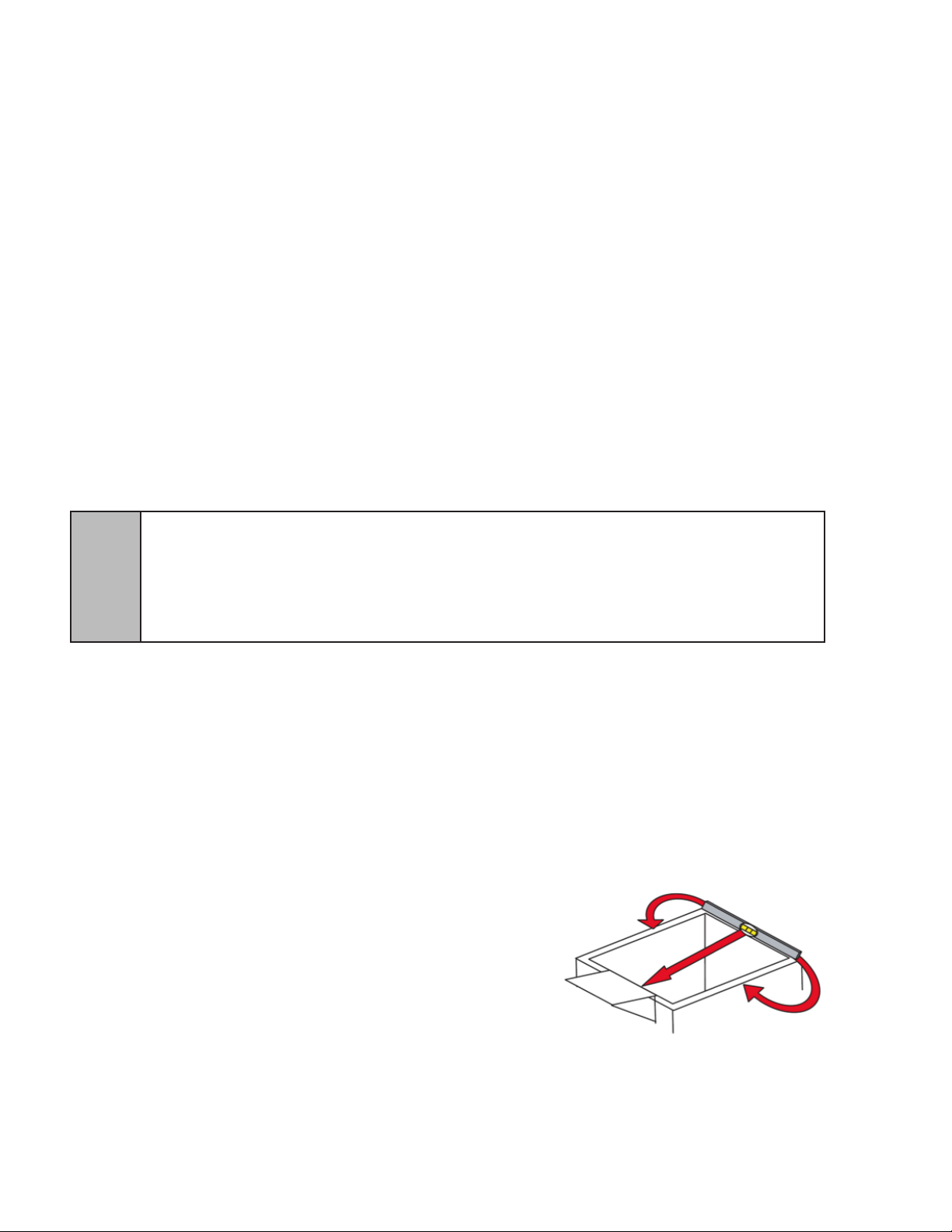
1.5 LEVELING THE DISPENSER
In order to facilitate proper dispenser drainage and
carbonation, ensure that the dispenser is level, front to back
and side to side. Place a level on the top of the rear edge
of the dispenser. The bubble must settle between the level
lines. Repeat this procedure for the remaining three sides.
Level unit if necessary. For optimum performance place the
unit at a 0 degree tilt. The maximum tilt is 5 degrees.
1.6 CONNECTING THE DRAIN
A. Remove cup rest. Lift splash plate up and pull out and down on the bottom to remove.
B. Remove the drip tray from the unit and connect the drain tube to the drain tting located on the
back.
C. Route the drain tube to a suitable drain and replace the unit’s drip tray.
10
Page 11

1.7 FILLING UNIT WITH WATER
A. Remove the bonnet from the unit.
B. Remove the (yellow) plastic plug (located in the front of the unit’s compressor deck) from the
unit’s ll hole.
C. Using a funnel or tube, ll the water bath compartment with water until it ows out of the
overow tube into the drip tray.
CAUTION THE WATER BATH COMPARTMENT MUST BE FILLED WITH WATER BEFORE PLUGGING IN THE UNIT,
OTHERWISE THE COMPRESSOR DECK AND CONDESOR FAN MAY NOT OPERATE PROPERLY
PRECAUCIÓN EL COMPARTIMIENTO DE BAñO DE AGUA DEBA ESTAR LLENO DE AGUA ANTES DE ENCHUFAR
LA UNIDAD PUES, DE LO CONTARIO, LA PLATAFORMA DEL COMPRESOR Y EL VENTILADOR DEL
CONDENSADOR NO FUNCIONARíAN CORRECTAMENTE.
!
ATTENTION LE COMPARTIMENT DE BAIN-MARIE DOIT ÊTRE REMPLI AVEC DE L’EAU
AVANT DE BRANCHER L’APPAREIL, SINON LA PLATEFORME DU COMPRESSEUR ET LE VENTILATEUR DU CONDENSATEUR PEUVENT NE PAS FONCTIONNER CORRECTEMENT.
D. Replace the plastic plug.
1.8 CONNECTING TO ELECTRICAL POWER
NOTE: Adhere to the ELECTRICAL Warnings/Cautions, Page 8.
GROUNDING WARNING THE DISPENSER MUST BE PROPERLY ELECTRICALLY GROUNDED TO AVOID
SERIOUS INJURY OR FATAL ELECTRICAL SHOCK. THE POWER CORD HAS A THREE-PRONG GROUNDED
PLUG. IF A THREE-HOLE GROUNDED ELECTRICAL OUTLET IS NOT AVAILABLE, USE AN APPROVED METHOD TO
GROUND THE UNIT. FOLLOW ALL LOCAL ELECTRICAL CODES WHEN MAKING CONNECTIONS. EACH
DISPENSER MUST HAVE A SEPARATE ELECTRICAL CIRCUIT. DO NOT USE EXTENSION CORDS. DO NOT
CONNECT MULTIPLE ELECTRICAL DEVICES ON THE SAME OUTLET.
ADVERTENCIA, PUESTA A TIERRA ES NECESARIO PONER A TIERRA ELÉCTRICAMENTE EL
DISPENSADOR PARA EVITAR LESIONES GRAVES E INCLUSO ELECTROCHOQUES FATALES. EL CABLE DE
ALIMENTACIÓN TIENE UN ENCHUFE PUESTO A TIERRA DE 3 CLAVIJAS. SI NO SE DISPONE DE UN TOMA
ELÉCTRICO CONECTADO A TIERRA DE TRES AGUJEROS, USE UN MÉTODO APROBADO PARA PONER A TIERRA
LA UNIDAD. AL HACER LAS CONEXIONES, RESPETE TODOS LOS CÓDIGOS ELÉCTRICOS LOCALES. CADA
F
A. If the unit is equipped with a built-in carbonator, disconnect the power supply to the carbonator
motor by disconnecting the four pin connector located near the top of the electrical control box
on the refrigeration deck.
B. Check the dispenser serial number plate for correct electrical requirements of unit. Do not plug
C. Route and plug the power supply cord to a grounded electrical outlet that supplies the proper
voltage and amperage rating for this unit. This will turn on the refrigeration system and allow it
immediately, but the compressor and fan motor have a ve (5) minute delay.
DISPENSADOR DEBE TENER UN CIRCUITO ELÉCTRICO INDEPENDIENTE. NO USE CABLES DE EXTENSIÓN. NO
CONECTE VARIOS DISPOSITIVOS ELÉCTRICOS AL MISMO TOMACORRIENTE.
EXIGENCES DE MISE À LA TERRE LA DISTRIBUTRICE DOIT ÊTRE MISE À LA TERRE ÉLECTRIQUEMENT
CORRECTEMENT POUR ÉVITER DES BLESSURES GRAVES OU UNE DÉCHARGE ÉLECTRIQUE MORTELLE. LE
CORDON D’ALIMENTATION A UNE FICHE À TROIS BRANCHES MISE À LA TERRE. SI AUCUNE PRISE DE
COURANT ÉLECTRIQUE À TROIS TROUS N’EST DISPONIBLE, UTILISEZ UNE MÉTHODE APPROUVÉE POUR
METTRE L’UNITÉ À LA TERRE. RESPECTEZ TOUS LES CODES ÉLECTRIQUES LOCAUX LORSQUE VOUS FAITES
DES CONNEXIONS. CHAQUE DISTRIBUTRICE DOIT AVOIR UN CIRCUIT ÉLECTRIQUE SÉPARÉ. N’UTILISEZ PAS
DE CORDONS PROLONGATEURS. NE BRANCHEZ PAS PLUSIEURS APPAREILS ÉLECTRIQUES À LA MÊME PRISE
DE COURANT.
into wall electrical outlet unless the current shown on the serial number plate agrees with
local current available.
to start cooling while completing the rest of the installation. The agitator motor will start
F
CAUTION FAILURE TO DISCONNECT THE MOTOR POWER SUPPLY WILL DAMAGE THE CARBONATOR
MOTOR, THE PUMP AND VOID THE WARRANTY.
PRECAUCIÓN SI NO DESCONECTA LA ALIMENTACIÓN ELÉCTRICA DEL MOTOR PODRÍAN DAÑARSE LA BOMBA
Y EL MOTOR DEL CARBONATADO Y ANULAR LA GARANTÍA.
ATTENTION LE FAIT DE NE PAS MAINTENIR LE DÉGAGEMENT SPÉCIFIÉ FERA SURCHAUFFER LE
COMPRESSEUR ET AURA COMME CONSÉQUENCE UNE DÉFAILLANCE DU COMPRESSEUR.
11
Page 12

1.9 CONNECTING TO WATER SUPPLY - CARBONATED WATER INLET
NOTE: Adhere to the WATER SUPPLY Warnings/Cautions, Page 9.
A. Using appropriate tubing and ttings, connect carbonated water supply line to water source.
DO NOT CONNECT TO CARBONATOR AT THIS TIME.
B. Flush water supply line thoroughly.
NOTE: If the water source is above 50 PSIG (0.345 MPA), cut tubing assembly and install Water
Regulator Kit (PN 18-0253/02) as shown in kit instruction sheet.
C. Route tubing through hole in counter and through opening behind splash plate and connect to
carbonator pump using a are seal washer (PN 05-0017). Use a back-up wrench to prevent
damage to carbonator pump.
D. Leave 12 inches (305 mm) of extra tubing length below the counter for servicing and moving
the dispenser.
E. Turn on water supply and check for leaks.
F. Using test gauge assembly (PN 22-0138), set regulator at a maximum of 50 PSIG (0.345 MPA).
1.10 CONNECTING TO WATER SUPPLY - PLAIN WATER INLET
NOTE: Adhere to the WATER SUPPLY Warnings/Cautions, Page 9.
A. Using appropriate tubing and ttings, connect plain water supply line to water source. DO NOT
CONNECT TO DISPENSER AT THIS TIME
B. Flush plain water supply line thoroughly.
C. Route tubing through hole in counter and through opening behind splash plate and connect to
check valve on plain water inlet (labeled “Water”). Use a back-up wrench to prevent damage to
the check valve or water line.
D. Leave 12 inches (305 mm) of extra tubing length below the counter for servicing and moving
the dispenser.
E. Turn on water supply and check for leaks.
1.11 CONNECTING THE CO2 SUPPLY
A. Verify the CO2 tank valve is in the closed position. Connect the high pressure CO2 regulator
assembly to CO2 cylinder. Use a new CO2 tank washer if regulator does not have built-in o-ring
seal.
B. Place CO2 cylinder upright in a cool service location (under counter, etc.), and secure it with a
safety chain.
C. Using tubing and ttings from installation kit connect tubing assembly to tank mount regulator
using are seal washer (PN 05-0011). Use a back-up wrench to prevent damage to regulator
assembly.
D. Route gas line through hole in counter and through opening behind the dispenser splash plate.
Leave 12 inches (305 mm) of extra tubing length below the counter for servicing and moving
the dispenser.
F. Remove the protective plug from the CO2 manifold (located on top of mini pumps on left side of
unit) and connect the CO2 supply line using a 1/4 inch elbow (supplied in installation kit.)
WARNING DO NOT TURN ON THE CO2 SUPPLY AT THIS TIME.
ADVERTENCIA NO CONECTE TODAVÍA LA ALIMENTACIÓN DE CO2.
5
G. If dispenser does not have built in syrup pumps, connect directly to the carbonator CO2 inlet
check valve.
H. Attach a CO2 supply line from each of the gal syrup containers to the low pressure regulator
and pressurize the containers.
AVERTISSEMENT N’OUVREZ PAS L’ALIMENTATION EN CO2 À CE MOMENT.
12
Page 13

1.12 CONNECTING BAG-IN-BOX (BIB) SYRUP SUPPLY TO UNITS WITH BUILT-IN SYRUP PUMPS
WARNING THE SYRUP INLET TUBE ASSEMBLIES (SHIPPED WITH THE INSTALLATION KIT) ARE EIGHT (8) FEET
(2.4 M) LONG. THESE LINES CAN BE EXTENDED UP TO A MAXIMUM OF 12 FEET (3.7 M). THE MAXIMUM HEIGHT
OF THE PUMPS ABOVE THE LOWEST BIB PACKAGE SHOULD NOT EXCEED EIGHT (8) FEET (2.4 M). IF EITHER
THE HEIGHT OF PUMPS OR LENGTH OF INLET LINE LIMITATIONS IS EXCEEDED, REMOTE SYRUP PUMPS OR
PRESSURIZED SYRUP CONTAINERS SHOULD BE USED.
ADVERTENCIA LOS CONJUNTOS DE TUBERÍA DE ENTRADA DE SYRUP (SUMINISTRADOS CON EL KIT DE
INSTALACIÓN) TIENEN OCHO (8) PIES (2,4 M) DE LARGO. ESTAS LÍNEAS SE PUEDEN EXTENDER HASTA UN
MÁXIMO DE 12 PIES (3,7 M). LA ALTURA MÁXIMA DE LAS BOMBAS POR ENCIMA DEL PAQUETE BIB MÁS BAJO
NO DEBE SUPERAR LOS OCHO (8) PIES (2,4 M). SI SE SUPERAN LAS LIMITACIONES EN CUANTO A LA ALTURA
!
DE LAS BOMBAS O EL LARGO DE LA LÍNEA DE ENTRADA, HAY QUE USAR CONTENEDORES DE SYRUP
PRESIONIZADOS O BOMBAS DE SYRUP REMOTAS.
AVERTISSEMENT LES GROUPES DE TUBE D’ENTRÉE DE SIROP (EXPÉDIÉES AVEC LA TROUSSE
D’INSTALLATION) SONT HUIT (8) PIEDS (2,4 M) DE LONG. CES LIGNES PEUVENT ÊTRE PROLONGÉES JUSQU’À
UN MAXIMUM DE 12 PIEDS (3,7 M). LA HAUTEUR MAXIMUM DES POMPES AU-DESSUS DU SAC DE CONCENTRÉ
LE PLUS BAS NE DOIT PAS DÉ PASSER HUIT (8) PIEDS (2,4 M). SI LA HAUTEUR DES POMPES OU LA LIMITE DE
LONGUEUR DE LA CONDUITE D’ENTRÉE EST DÉPASSÉE, DES POMPES DE SIROP À DISTANCE OU DES
CONTENEURS DE SIROP PRESSURISÉS DOIVENT ÊTRE UTILISÉS.
A. Remove the protective caps from the syrup pump inlets and connect syrup inlet tube
assemblies furnished in the installation kit to the syrup pumps. Lubricate o-rings before
installation using an FDA approved lubricant or clean water. Be careful not to cut o-rings when
installing in pump.
B. Mark syrup tube assemblies at BIB hose connector end with product ID tape.
C. Route the syrup supply tubes from the unit through hole in counter to the BIB syrup supply.
D. Dip hose connectors in a cup of warm, clean water.
E. Attach the BIB hose connectors to the appropriate syrup avor.
1.13 CONNECTING TO BAG-IN-BOX (BIB) SYRUP SUPPLY TO REMOTE SYRUP PUMPS
A. To connect CO2 regulator assembly to the CO2 cylinder, see Section 1.11, Steps A - C.
B. Place the remote BIB syrup supply and pumps in a convenient location.
C. Attach the syrup supply tubes to the dispenser’s syrup inlet fittings (located behind the splash
plate) using a 21/32 inch (17.0 mm) Oetiker clamp for each syrup flavor.
D. Route the syrup supply tubes to the remote syrup pumps.
E. Complete installation of the remote syrup pump system following the manufacturer’s
instructions.
1.14 CONNECTING TO REMOTE PRESSURIZED SYRUP SUPPLY (FIGAL)
A. To connect CO2 regulator assembly to the CO2 cylinder, see Section 1.11, Steps A - C.
B. Place the five gallon (figal) syrup containers and the CO2 cylinder and regulator set in a
convenient location.
C. Attach the syrup supply tube assembly to the dispenser’s syrup inlet fittings (located behind the
splash plate) using a 21/32 inch (17.0 mm) Oetiker clamp for each syrup flavor.
D. Route the syrup supply tubes to the figal syrup containers and attach them to the appropriate
syrup flavor.
1.15 PURGING THE CARBONATION SYSTEM
A. Set the adjustable back blocks to deliver carbonated water (see Section 1.20).
B. The relief valve for the built-in carbonator is located on the right hand side of the unit’s
carbonator deck. Lift the yellow lever on the top of the relief valve until water ows from the
holes in the relief valve. Then release the relief valve.
C. Reconnect the control box to the carbonator pump.
D. Back off on the CO2 regulator pressure adjusting screw all the way. Open the CO2 cylinder
handle slowly. Turn the CO2 pressure regulator up slowly to 75 PSIG (0.510 MPA).
E. Activate a dispensing valve until water and syrup are owing steadily from the valve.
F. Repeat procedure “D” for each valve.
G. Check all of the unit’s syrup, water and CO2 connections for leaks and repair if necessary.
NOTE: To check for CO2 leaks, close the valve on the CO2 tank and observe for ve (5)
minutes if the pressure to the system drops. Open the cylinder valve after check.
H. Replace the unit’s bonnet, splash plate and cup rest.
13
Page 14
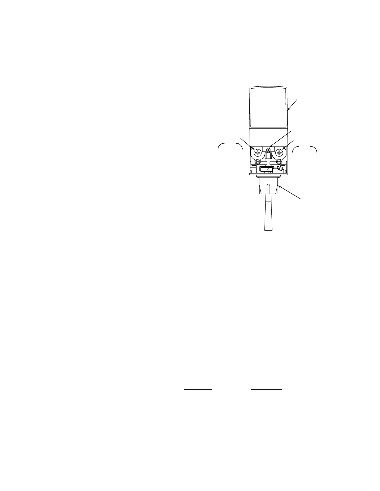
1.16 PURGING THE WATER AND SYRUP SYSTEMS
I.D. PANEL
(Shown in
open position)
COVER SCREW
NOZZLE (WITH
DIFFUSER INSIDE)
FLOW CONTROL
SYRUP
DecreaseIncrease
FLOW CONTROL
WATER
DecreaseIncrease
A. Set the adjustable back blocks to deliver plain water (see Section 1.20).
B. Open a dispensing valve until water and syrup are owing steadily from the valve.
C. Repeat procedure “A” for each valve.
D. Check all of the unit’s syrup and water connections for leaks and repair if necessary.
E. Replace the unit’s bonnet, splash plate and cup rest.
1.17 ADJUSTING WATER FLOW (LEV®)
A. The water ow can be adjusted between 1.25 oz/sec (37 ml/sec)
and 2.50 oz/sec (74 ml/sec) on all dispensing valves using the
following procedures.
B. The refridgeration unit should have been running for at least one
(1) hour before you attempt to brix the valves. The drink
temperature should be no higher than 40°F (4.4°C) when the brix
is set. This is best done after the unit has made
an ice bank.
C. Slide up ID panel until ow controls are exposed
(see Figure 1)
D. Remove nozzle by twisting counter clockwise and
pulling down.
E. Remove diffuser by pulling down.
F. Install Lancer (yellow) syrup separator (PN 54-0031) in place of
nozzle.
G. Activate dispensing valve to ll separator syrup tube.
H. Hold a Lancer brix cup under the syrup separator and dispense
water and syrup into cup for four (4) seconds. Divide number of
ounces (ml) of water in cup by four (4) to determine water ow
rate per second
I. To obtain the proper ow, use a screwdriver to adjust water ow
control (see Figure 1).
J. Repeat process for each valve.
Typical Valve Adjustment, LEV®
Figure 1
1.18 ADJUSTING WATER TO SYRUP (RATIO) BRIX (LEV®)
A. Hold the Lancer brix cup under the syrup separator and activate valve. Check brix.
B. To obtain the proper brix, use screwdriver to adjust syrup ow control (see Figure 1).
C. Once proper ratio is obtained repeat to verify.
D. Remove syrup separator (PN 54-0031 installed in Section 1.18.F above).
E. Install diffuser and nozzle.
F. Slide down ID panel.
G. Repeat process for each valve.
1.19 VOLUMETRIC VALVE ADJUSTMENT
NOTE: The Volumetric Valve is an optional valve with the Delta III Dispenser (Fig. 2).
A. Valve Specications
1. Finished Drink Flow Rates
3.0 ounces per second (88.7 ml/sec), as shipped
2.25 ounces per second (66.6 ml/sec)
1.5 ounces per second (44.4 ml/sec)
2. Flowing Pressure Requirements MINIMUM MAXIMUM
Water 40 PSIG (0.276 MPA) 110 PSIG (0.758 MPA)
Syrup 20 PSIG (0.138 MPA) 70 PSIG (0.483 MPA)
3. Electrical Requirement: 24 VAC, 50/60Hz
14
Page 15
1.19 VOLUMETRIC VALVE ADJUSTMENT - CONTINUED
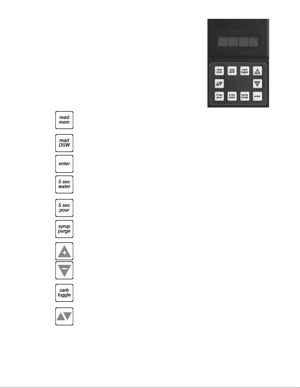
B. Programmer Operating Procedures
1. Connecting
a. Remove the ID panel from the front of the valve.
b. Insert the programmer’s 10-pin connector into the ID
Panel plug on the front of the circuit board.
c. When properly connected, the programmer will run
a self diagnostic test. The display will show all “8”s
with the decimal points lighted.
After three (3) seconds, the display indicates the
setting of the dip switches.
d. If the programmer does not run its diagnostic test
properly, disconnect it and try plugging it in again. If
the programmer still fails, replace the programmer.
2. Functions
Read Memory: Press this button to read and display
the current settings programmed into the valve memory
(i.e., S/W revision, ratio, andcarb/non carb settings).
Read Dip Switches: Press this button to read the dip switch settings (applies only to
valves manufactured before July 1997). nOTE: Dip switches were used on some eld test
valves (refer to 28-0301, 12/20/95).
Write Memory: Press this button to write the programmer’s displayed ratio and carbonation
settings into the valve’s memory.
Handheld Programmer,
Figure 2
Volumetric Valve
Timed 5 Second Water: Press this button to pour water for ve (5) seconds. The
programmer will display the ratio, the counts from the owmeter, the ow rate in oz/sec,
and the ow rate in ml/sec.
Timed 5 Second Pour: Press this button to dispense a ve (5) second pour of water and
syrup for ratio testing. When complete, the programmer displays the ratio, carbonation
settings, and total Flowmeter counts.
Syrup Purge: Press and release to dispense a six (6) second syrup purge. Continue holding
to purge syrup from system.
Ratio + (Plus): Pressing this button will increase the ratio number on the display.
Ratio - (Minus): Pressing this button will decrease the ratio number on the display.
Carb Toggle: Pressing this button will toggle the carbonation setting from carbonated “C”
to plain water “n” (non-carbonated).
Pour/Stop: Press this button to manually pour a mixed drink. This button will also stop a
timed pour.
15
Page 16

1.19 VOLUMETRIC VALVE ADJUSTMENT - FUNCTIONS, CONTINUED
TOP VIEW
C. Setting the Ratio/Carbonation
1. Connect the programmer to the Valve.
2. Press the “Read Mem” button.
3. Press the “Ratio +” or the “Ratio -” key until the desired ratio is displayed.
4. Verify the drink type. Press “Carb Toggle”to select “C” for carbonated or “n” for
non-carbonated.
5. Press the “Enter” button to program the valve with the setting on the display.
6. Verify Ratio by pressing “Read Mem”.
7. Disconnect the programmer.
1.20 SETTING 3-WAY ADJUSTABLE BACK BLOCKS FOR PLAIN OR CARBONATED WATER
A. For a six-valve unit, valves 3, 4, and 5 can be set to deliver either plain or carbonated water.
On a ve-valve unit, valves 3 and 4 are adjustable. Refer to Figure 3 or to the label on the front
support plate behind the splash plate.
B. The shut-off stem on the left side of the back block controls the ow of plain or carbonated
water. The stem has a straight side and a double curved side when looking down at the back
block. To set the adjustable back block to deliver plain water, turn the shut-off stem to
where the straight side of the stem is facing to the left. To set the back block to deliver
carbonated water, turn the shut-off stem to where the straight side faces to the right.
When the shut-off stem is at its midpoint, with the straight side facing forward, the ow of either
plain or carbonated water is shutoff.
C. Be sure the shut-off stem is fully turned to the desired position, or the ow of water will be
restricted.
3 - WAY BACK BLOCK
REAR VIEW
SY
LEGEND:
SY = SYRUP LINE
S = SODA LINE
PW = PLAIN WATER LINE
PN 06-2874
Setting 3-Way Adjustable Back Blocks
(SHUT-OFF ORIENTATION)
PLAIN WATER ON
S
PW
CARB WATER ON
VALVE CLOSED
Figure 3
16
Page 17

2. CLEANING AND SANITIZING
2.1 GENERAL INFORMATION
Lancer equipment is shipped from the factory cleaned and sanitized in accordance with NSF guide
lines. After installation, it is the responsibility of the installer to clean and sanitize the dispenser
again. The operator of the equipment must provide continuous maintenance as required by this
manual and state and local health department guidelines to ensure proper operation and sanitation
requirements are maintained.
For optimum dispenser performance and highest drink quality, follow the instructions listed for
cleaning your dispenser. Cleaning and sanitizing should be accomplished only by trained
personnel. If other equipment is being cleaned, follow the guidelines established by the
manufacturer for that equipment.
USE SANITARY GLOVES.
OBSERVE APPLICABLE SAFETY PRECAUTIONS.
x DO NOT USE A WATER JET TO CLEAN OR SANITIZE THE UNIT
x DO NOT DISCONNECT WATER LINES WHEN CLEANING AND SANITIZING SYRUP LINES, TO
AVOID CONTAMINATION.
x DO NOT USE STRONG BLEACHES OR DETERGENTS; THESE CAN DISCOLOR AND
CORRODE VARIOUS MATERIALS.
x DO NOT USE METAL SCRAPERS, SHARP OBJECTS, STEEL WOOL, SCOURING PADS,
ABRASIVES, OR SOLVENTS ON THE DISPENSER.
x DO NOT USE HOT WATER ABOVE 140º F (60º C). THIS CAN DAMAGE THE DISPENSER.
x DO NOT SPILL SANITIZING SOLUTION ON ANY CIRCUIT BOARDS. INSURE ALL SANITIZING
SOLUTION IS REMOVED FROM THE SYSTEM.
2.2 CLEANING SOLUTION
Mix a mild, non-abrasive detergent (e.g. Sodium Laureth Sulfate, dish soap) with clean, potable
water at a temperature of 90 to 110°F (32 to 43°C). The mixture ratio is one ounce of cleaner to two
gallons of water. Prepare a minimum of ve gallons of cleaning solution. Do not use abrasive
cleaners or solvents because they can cause permanent damage to the unit. Rinsing must be
thorough, using clean, potable water at a temperature of 90 to 110°F (32 to 43°C). Extended
lengths of product lines may require that an additional volume of cleaning solution be prepared.
2.3 SANITIZING SOLUTION
Prepare sanitizing solutions in accordance with the manufacturer’s written recommendations and
safety guidelines. The solution must provide 50 to 100 parts per million (PPM) chlorine (e.g. Sodium
Hypochlorite or bleach). A minimum of ve gallons of sanitizing solution should be prepared. Any
sanitizing solution may be used as long as it is prepared in accordance with the manufacturer’s
written recommendations and safety guidelines, and provides 50 to 100 parts per million (PPM)
chlorine. Extended lengths of product lines may require that an additional volume of sanitizing
solution be prepared.
OTHER SUPPLIES NEEDED:
• Sanitary gloves • Clean cloth towels • Extra nozzle • Bucket
• Small brush (PN 22-0017), included with installation kit
17
Page 18

2.4 SCHEDULED MAINTENANCE
AS NEEDED
Keep exterior surfaces of dispenser (including the drip tray and cup rest) clean using a clean,
damp cloth.
DAILY
A. Remove the nozzle and diffuser from each valve and wash them in warm water.
B. Remove the cup rest and wash in warm soapy water.
C. Pour warm soapy water into the drip tray and wipe with a clean cloth.
D. With a clean cloth and warm soapy water, wipe off all of the unit’s exterior surfaces.
E. Replace the cup rest, valve diffusers and valve nozzles.
SCHEDULED MAINTENANCE - WEEKLY
A. Check the ow and brix of each LEV® valve following the brixing instructions given in Sections
1.17 and 1.18.
B. Remove the unit’s bonnet and check the level of water in the water bath. Replenish as required,
and replace the bonnet.
SCHEDULED MAINTENANCE - MONTHLY
A. Unplug the dispenser from its power source.
B. Remove the bonnet and, using a soft brush, clean the dirt from the unit’s condenser.
C. Replace the bonnet. Plug in the unit.
SCHEDULED MAINTENANCE - EVERY SIX (6) MONTHS
A. Unplug the dispenser from its power source.
B. Clean and sanitize the unit using the appropriate procedures outlined in Section 2.
SCHEDULED MAINTENANCE - YEARLY
A. Clean water bath interior, including evaporator coils and refrigeration components.
B. Clean the entire exterior of the unit.
C. Sanitize syrup lines.
NOTE: Because of difculty in rinsing, detergent solutions should not be introduced into the
carbonator.
CAUTION FOLLOWING SANITIZATION, RINSE WITH END-USE PRODUCT UNTIL THERE IS NO AFTERTASTE. DO
NOT USE A FRESH WATER RINSE. THIS IS A NSF REQUIREMENT. RESIDUAL SANITIZING SOLUTION LEFT IN THE
SYSTEM CREATES A HEALTH HAZARD.
PRECAUCIÓN DESPUÉS DE LA ESTERILIZACIÓN, ENJUAGUE CON EL PRODUCTO FINAL HASTA QUE
ELIMINAR EL SABOR QUE QUEDA. NO ENJUAGUE CON AGUA FRESCA. ÉSTA ES UNA EXIGENCIA DE NSF. SI
!
2.5 AMBIENT PROCESS (SYRUP LINE CLEANING)
A. The ambient process is the most common method for cleaning and sanitizing dispenser
equipment. The detergent should be as recommended and the sanitizer should be low pH (7.0)
chlorine solution.
B. Disconnect syrup containers and remove product from tubing.
C. Rinse the lines and ttings with clean room temperature water to remove all traces of residual
product.
D. Fill lines with a low-sudsing, non-perfumed, and easily rinsed detergent solution. The solution
should be prepared in accordance with the manufacturers recommendations. Make sure the
lines are completely lled and allow to stand for at least 10 minutes.
E. Flush the detergent solution from the lines with clean water.
F. Fill the lines with a low pH (7.0) chlorine solution containing at least 100 PPM (100mg/L)
available chlorine. Flow sanitizing solution through dispenser until output tests to full 100 PPM
(100mg/L) concentration. Allow to stand for 15 minutes.
G. Reconnect syrup containers and ready Unit for operation.
H. Draw drinks to rell lines and ush the chlorine solution from the dispenser.
I. Taste the beverage to verify that there is no off taste.
QUEDA SOLUCIÓN DE ESTERILIZACIÓN EN EL SISTEMA, GENERA UN PELIGRO PARA LA SALUD.
ATTENTION DÉFENSE DE RINCER L’OUTIL À L’EAU FRAICHE IMMÉDIATEMENT APRÈS UN TRAITEMENT
SEPTIQUE.EN CAS DE APRÈS-GOÛT, NE PURGER AVEC LE PRODUIT FINAL UNE EXIGENCE NSF.
18
Page 19

Diffuser
Assembly
Nozzle
2.6 VALVE CLEANING
A. LEV® Valves may be cleaned and sanitized as described in Section 3.2.
NOTE: Refer to the current revision level of Lancer Operations Manual 28-0027/05 for complete
information on the LEV®.
1. Remove cover and disconnect power so the valve will not be activated during the cleaning
procedure. Remove nozzle and diffuser. Wash these parts in cleaning solution; then immerse
them in a bath of sanitizing solution for 15 minutes.
2. Visually inspect around nozzle area for syrup residue. This area may be cleaned with warm
water and cloth or with the nozzle brush supplied. Wipe off dispensing lever (if valve is so
equipped).
3. Wearing sanitary gloves, remove, drain and air dry the nozzle and diffuser.
4. Wearing sanitary gloves, replace diffuser, twist nozzle in place.
5. Connect power and replace cover. Valve is ready for operation.
B. VOLUMETRIC VALVE CLEANING AND SANITIZING PROCEDURES
NOTE: The Volumetric Valve is an optional valve with the Delta III Dispenser. Refer to the Lancer
Operations Manual 28-0301/05 for complete information on the Volumetric Valve.
1. Daily nozzle/Diffuser Cleaning (Figure 4)
a. Remove nozzle by twisting it counter-clockwise and pulling it down.
b. Pull the diffuser assembly down to remove it from the valve.
c. Wash the nozzle and diffuser with warm water.
d. If needed, apply 111 lubricant to the o-ring on the diffuser assembly. Then, use care to
press the o-ring into the diffuser mounting area on the underside of the valve.
e. Verifty the nozzle o-ring, is in place around the nozzle mounting area on the valve. If
necessary, slide a new nozzle o-ring onto the nozzle mounting area.
f. Install the nozzle by inserting it into the bottom plate. Twist the nozzle clockwise to
lock in place.
2. Monthly Nozzle/Diffuser sanitizing
Figure 4
Nozzle/Diffuser
a. Separately prepare both the Cleaning and Sanitizing Solutions
(refer tp page 19).
b. Cleaning Procedure
1. Disconnect power, so the valve will not be inadvertently
activated while cleaning.
2. Remove nozzle by twisting it counter-clock wise and
pulling the nozzle down.
3. Pull the diffuser assembly down to remove it from the valve.
4. Wash the nozzle and diffuser with the cleaning solution.
5. Immerse the nozzle and diffuser in a bath of the sanitizing
solution for 15 minutes.
6. While the parts are in the sanitizing solution, visually inspect
around the nozzle mounting area on the valve for syrup
Diffuser
Assembly
residue. Using a cloth or nozzle brush and warm water,
clean this area.
Nozzle
7. Wipe off the dispensing lever (if so equipped) and any other
areas that may have been splashed by syrup.
NOTE: sanitary gloves are required for the following: steps 8-13.
8. Remove, drain, and air dry the nozzle and diffuser.
9. Carefully press the diffuser into the mounting area on the underside of the valve.
10. Make certain the nozzle o-ring, is in place around the nozzle mounting area on the
valve. If necessary, slide a new nozzle o-ring onto the nozzle mounting area.
11. Wearing sanitary gloves, install the nozzle by inserting it into the bottom plate and
twisting it clockwise to lock it in place.
12. Connect power and replace cover. Valve is ready for operation.
13. Draw drinks to ush residual sanitizing solution. Taste the beverage to verify that there
is no off taste. If an off taste is found, additional ushing may be required.
19
Page 20

B. VOLUMETRIC VALVE CLEANING AND SANITIZING PROCEDURES (CONTINUED)
3. Valve and System Sanitizing
The complete valve and dispenser system must be sanitized during initial installation.
Follow the manufacturer’s instructions when scheduling and conducting dispenser
sanitizing. The valve must be sanitized once every two weeks. The valve may remain
on the dispensing tower during the sanitizing process.
CAUTION FOLLOWING SANITIZATION, RINSE WITH END-USE PRODUCT UNTIL THERE IS NO AFTERTASTE. DO
NOT USE A FRESH WATER RINSE. THIS IS A NSF REQUIREMENT. RESIDUAL SANITIZING SOLUTION LEFT IN THE
SYSTEM CREATES A HEALTH HAZARD.
PRECAUCIÓN DESPUÉS DE LA ESTERILIZACIÓN, ENJUAGUE CON EL PRODUCTO FINAL HASTA QUE
ELIMINAR EL SABOR QUE QUEDA. NO ENJUAGUE CON AGUA FRESCA. ÉSTA ES UNA EXIGENCIA DE NSF. SI
!
C. SYRUP PURGE PLUG (FIGURE 5)
1. The Syrup Purge Plug (PN 52-1912), places the valve
in continuous syrup side operation. The targeted uses
for the purge plug consist of priming the syrup line on
an initial Volumetric Valve install, and for cleaning and
sanitization of the syrup side of the dispensing unit.
2. Operation of the syrup purge plug is as follows:
NOTE: With a standard 75 VA transformer, up to six (6)
Volumetric Valves can be operated in the syrup purge
mode simultaneously.
a. Turn off electrical power to all valves.
b. Install syrup purge plugs into the valve or valves to be primed or sanitized. The syrup
purge plug installs in the ten-pin connector of the Volumetric Valve circuit board.
c. Turn on electrical power to the valves. At this time, the syrup side of the valves will begin
continuous operation.
d. When through with the priming or sanitization operation, syrup purge operation can be
stopped in either of two ways:
Method 1: Turn off electrical power to all valves, remove syrup purge plugs from the valves.
Turn on electrical power to all valves. Tap valve lever or push button to ensure proper
operation of all valves.
Method 2: Remove syrup purge plug from the valves while they are in purge
operation. In this case, the valve may continue in the purge mode for up to six (6)
seconds after removal of the plug (this is normal). Tap valve lever or push button to ensure
proper operation of all valves.
QUEDA SOLUCIÓN DE ESTERILIZACIÓN EN EL SISTEMA, GENERA UN PELIGRO PARA LA SALUD.
ATTENTION DÉFENSE DE RINCER L’OUTIL À L’EAU FRAICHE IMMÉDIATEMENT APRÈS UN TRAITEMENT
SEPTIQUE.EN CAS DE APRÈS-GOÛT, NE PURGER AVEC LE PRODUIT FINAL UNE EXIGENCE NSF.
SYRUP PURGE
52-1912
Figure 5
Syrup Purge Plug
!
CAUTION FOLLOWING SANITIZATION, RINSE WITH END-USE PRODUCT UNTIL THERE IS NO AFTERTASTE. DO
NOT USE A FRESH WATER RINSE. THIS IS A NSF REQUIREMENT. RESIDUAL SANITIZING SOLUTION LEFT IN THE
SYSTEM CREATES A HEALTH HAZARD.
PRECAUCIÓN DESPUÉS DE LA ESTERILIZACIÓN, ENJUAGUE CON EL PRODUCTO FINAL HASTA QUE
ELIMINAR EL SABOR QUE QUEDA. NO ENJUAGUE CON AGUA FRESCA. ÉSTA ES UNA EXIGENCIA DE NSF. SI
QUEDA SOLUCIÓN DE ESTERILIZACIÓN EN EL SISTEMA, GENERA UN PELIGRO PARA LA SALUD.
ATTENTION DÉFENSE DE RINCER L’OUTIL À L’EAU FRAICHE IMMÉDIATEMENT APRÈS UN TRAITEMENT
SEPTIQUE.EN CAS DE APRÈS-GOÛT, NE PURGER AVEC LE PRODUIT FINAL UNE EXIGENCE NSF.
20
Page 21

2.7 CLEANING AND SANITIZING BAG-IN-BOX (BIB) SYSTEMS
A. Disconnect syrup quick disconnect coupling from syrup packages and connect coupling to a bag
valve removed from an empty Bag-in-Box package.
B. Place end of syrup inlet line, with bag valve attached, in a clean container lled with clean,
potable, room temperature water.
C. Place waste container under applicable dispensing valve. Activate valve until water is dispensed.
Flush and rinse line and ttings for a minimum of 60 seconds to remove all traces of residual
product.
NOTE: Extended lengths of product lines may require additional time for ushing and rinsing lines.
D. Prepare cleaning solution as described in section 3.2. Place end of syrup inlet line in container
lled with cleaning solution.
E. Place waste container under applicable dispensing valve. Activate valve and draw cleaning
solution through lines for a minimum of 60 seconds. This will ensure line is ushed and lled with
cleaning solution. Allow line to stand for at least 30 minutes.
F. Place end of syrup inlet line in a clean container lled with clean, potable, water at a temperature
of 90° to 110°F (32.2° to 43.3°C).
G. Place waste container under applicable dispensing valve. Activate valve to ush and rinse line
and ttings for a minimum of 60 seconds to remove all traces of cleaning solution. Test
dispenser in normal manner for proper operation. Taste dispensed product to ensure there is no
off-taste. If off-taste is found, additional ushing of syrup system may be required.
H. Prepare sanitizing solution as described in section 3.2. Place end of syrup inlet line in container
lled with sanitizing solution which has been prepared.
I. Activate valve and draw sanitizing solution through line for a minimum of 60
seconds. This will ensure line is ushed and lled with sanitizing solution. Allow line to stand for
at least 30 minutes.
J. Remove bag valve from quick disconnect coupling and reconnect syrup inlet line to syrup
package. Prep unit for operation.
K. Draw drinks and rell lines with end product to ush sanitizing solution from the dispenser.
L. Test dispenser in normal manner for proper operation. Taste dispensed product to ensure there
is no off-taste. If off-taste is found, additional ushing of syrup system may be required.
M. Repeat cleaning, rinsing, and sanitizing procedures for each valve circuit.
CAUTION FOLLOWING SANITIZATION, RINSE WITH END-USE PRODUCT UNTIL THERE IS NO AFTERTASTE. DO
NOT USE A FRESH WATER RINSE. THIS IS A NSF REQUIREMENT. RESIDUAL SANITIZING SOLUTION LEFT IN THE
SYSTEM CREATES A HEALTH HAZARD.
PRECAUCIÓN DESPUÉS DE LA ESTERILIZACIÓN, ENJUAGUE CON EL PRODUCTO FINAL HASTA QUE
ELIMINAR EL SABOR QUE QUEDA. NO ENJUAGUE CON AGUA FRESCA. ÉSTA ES UNA EXIGENCIA DE NSF. SI
!
2.8 CLEANING AND SANITIZING FIGAL SYSTEMS
A. Remove quick disconnect from syrup tank.
B. Using a clean plastic bristle brush and cleaning solution as described in section 3.2, scrub both
!
C. Using a mechanical spray bottle and a sanitizing solution prepared in accordance with the
instructions in Section 3.2, spray both halves of the quick disconnects. Allow to air dry.
D. Connect syrup line to a syrup tank lled with clean, potable, room temperature water. Connect
E. Place waste container under applicable dispensing valve. Activate valve until water is dispensed.
NOTE: Extended lengths of product lines may require additional time for ushing and lling lines.
QUEDA SOLUCIÓN DE ESTERILIZACIÓN EN EL SISTEMA, GENERA UN PELIGRO PARA LA SALUD.
ATTENTION DÉFENSE DE RINCER L’OUTIL À L’EAU FRAICHE IMMÉDIATEMENT APRÈS UN TRAITEMENT
SEPTIQUE.EN CAS DE APRÈS-GOÛT, NE PURGER AVEC LE PRODUIT FINAL UNE EXIGENCE NSF.
valves of the disconnect. Rinse with clean, potable water.
CAUTION DO NOT USE A WIRE BRUSH TO CLEAN VALVES.
PRECAUCIÓN NO USE CEPILLOS DE ALAMBRE PARA LIMPIAR LAS VÁLVULAS.
ATTENTION N’UTILISEZ PAS UNE BROSSE MÉTALLIQUE POUR NETTOYER LES SOUPAPES.
CO2 supply hose to tank and pressurize.
Flush and rinse line and ttings for a minimum of 60 seconds to remove all traces of residual
product, per NSF requirements stated above.
21
Page 22

2.8 CLEANING AND SANITIZING FIGAL SYSTEMS (CONTINUED)
WARNING DO NOT TURN ON THE CO2 SUPPLY AT THIS TIME.
ADVERTENCIA NO CONECTE TODAVÍA LA ALIMENTACIÓN DE CO2.
5
F. Disconnect CO2 supply hose from the water lled syrup tank.
G. Prepare cleaning solution as described in Section 3.2. Fill a tank with cleaning solution. Connect
H. Place waste container under applicable dispensing valve. Activate valve and draw cleaning
solution through lines for a minimum of 60 seconds. This will ensure line is ushed and lled with
NOTE: Extended lengths of product lines may require additional time for ushing and lling lines.
I. Disconnect CO2 supply hose from the tank.
J. Connect syrup line to a tank lled with clean water at a temperature of 90° to 110°F(32.2° to
K. Place waste container under applicable dispensing valve. Activate valve to ush and rinse line
dispenser in normal manner for proper operation. Taste dispensed product to ensure there is no
L. Disconnect CO2 supply hose from the tank.
M. Fill a tank with sanitizing solution prepared as described in Section 3.2. Connect syrup line to the
N. Remove dispensing valve nozzle (twist and pull down) and pull out center mixing bafe. Using
a plastic bristle brush and detergent soap solution, scrub the nozzle, mixing bafe, bottom of
O. Reassemble mixing bafe and nozzle.
P. Place waste container under applicable dispensing valve. Activate valve and draw sanitizing
Q. Disconnect CO2 supply hose from the tank.
R. Reconnect syrup lines to syrup containers (for example, quick disconnects, gal containers, etc.)
S. Draw drinks and rell lines with end product to ush sanitizing solution from the
T. Test dispenser in normal manner for proper operation. Taste dispensed product to ensure there
U. Repeat cleaning, rinsing, and sanitizing procedures for each valve/syrup circuit.
V. Clean exterior of unit as instructed in Section 3.2.
W. Using a spray bottle of sanitizing solution, spray the underside of all dispenser valves, valve
NOTE: Thoroughly rinse inside and outside of syrup tank that was used for sanitizing solution with
plain water to remove all solution residue.
AVERTISSEMENT N’OUVREZ PAS L’ALIMENTATION EN CO2 À CE MOMENT.
syrup line to the tank. Connect CO2 supply hose to tank and pressurize.
cleaning solution. Allow line to stand for at least 30 minutes.
43.3°C). Connect CO2 supply hose to tank and pressurize.
and ttings for a minimum of 60 seconds to remove all traces of cleaning solution. Test
off-taste. If off-taste is found, additional ushing of syrup system may be required.
tank. Connect CO2 supply hose to tank and pressurize.
dispensing valve, and cup lever. Rinse with clean water.
solution through line for a minimum of 60 seconds. This will ensure line is ushed and lled with
sanitizing solution. Allow line to stand for at least 30 minutes.
and ready unit for operation.
dispenser.
is no off-taste. If off-taste is found, additional ushing of syrup system may be required.
spouts and cup levers. Allow to air dry.
CAUTION FOLLOWING SANITIZATION, RINSE WITH END-USE PRODUCT UNTIL THERE IS NO AFTERTASTE. DO
NOT USE A FRESH WATER RINSE. THIS IS A NSF REQUIREMENT. RESIDUAL SANITIZING SOLUTION LEFT IN THE
SYSTEM CREATES A HEALTH HAZARD.
PRECAUCIÓN DESPUÉS DE LA ESTERILIZACIÓN, ENJUAGUE CON EL PRODUCTO FINAL HASTA QUE
ELIMINAR EL SABOR QUE QUEDA. NO ENJUAGUE CON AGUA FRESCA. ÉSTA ES UNA EXIGENCIA DE NSF. SI
!
3. CONVERTING FROM EXTERNAL PRESSURIZED SYRUP SUPPLY TO BIB WITH BUILT-IN SYRUP
PUMPS
This conversion can be accomplished. Contact Lancer for parts and instructions.
QUEDA SOLUCIÓN DE ESTERILIZACIÓN EN EL SISTEMA, GENERA UN PELIGRO PARA LA SALUD.
ATTENTION DÉFENSE DE RINCER L’OUTIL À L’EAU FRAICHE IMMÉDIATEMENT APRÈS UN TRAITEMENT
SEPTIQUE.EN CAS DE APRÈS-GOÛT, NE PURGER AVEC LE PRODUIT FINAL UNE EXIGENCE NSF.
22
Page 23

4. CONVERTING FROM BUILT-IN SYRUP PUMPS TO REMOTE PUMPS OR SYRUP TANKS
4.1 REMOVING EXISTING BUILT-IN SYRUP PUMPS
Figure 6
Shutoff open Shutoff closed
A. Disconnect the unit from the power supply and remove the bonnet.
B. Loosen the valve cover retaining screws and remove the valve covers.
C. Shut off the water supply to each Valve by turning the water shutoff knob (located on the left
hand side of the valve mounting block) clockwise until it stops (see Figure 6).
D. Prepare three to four (3 to 4) gallons of warm water in a suitable open container.
E. Disconnect the syrup supply lines from the BIB syrup supply, assemble a BIB adapter to the end
of each line, and place the line in the container of warm water.
F. Open each dispensing valve until the water owing from the valve shows no discoloration due to
syrup.
G. Remove the syrup supply lines from the warm water and open each dispensing valve to purge
the water from the system.
H. Turn off the CO2 supply to the unit and disconnect the CO2 supply line from CO2 inlet tting on
the built-in pump package.
I. Disconnect the syrup inlet lines from the built-in syrup pumps and remove them from the unit.
J. Disconnect the pump’s syrup outlet lines from the unit’s syrup inlet ttings.
K. Remove 1/8 inch barbed carbonator CO2 check valve, if one is present.
L. Remove the four (4) sheet metal screws that secure the pump assembly to the carbonator deck
and remove the pump assembly from the unit.
M. Remove braided inlet tubes and elbow. It will be necessary to cut the securing Oetiker clamps.
4.2 INSTALLING REMOTE PUMP OR SYRUP TANKS
A. Install new 1/4 inch male are CO2 carbonator check valve.
B. Connect the CO2 supply line to the carbonator check valve.
C. Connect the syrup outlet line from each remote pump to the appropriate syrup inlet tting on the
unit using a 1/4 inch Oetiker clamp.
NOTE: Each 1/4 inch braided syrup tube will be looped from the inlet line to the
remote pumps. Take caution not to bend, crimp, or kink the 1/4 inch tube at the loop. It may be nec-
essary to use a tie wrap.
D. Make all necessary connections on remote pump system or syrup tank.
E. Turn on water (25 to 50 PSIG)(0.172 to 0.345 MPA) and CO2 (70 to 80 PSIG)(0.483 to 0.552
MPA) supply.
F. Open each valve until syrup ow is established and check all connections for leaks.
G. Replace the bonnet and reconnect the unit to the power supply.
H. Open the water supply to each valve and replace the valve covers.
I. Brix the valves if necessary. (Refer to Sections 1.17 and 1.18 of this manual.)
23
Page 24

5. TROUBLESHOOTING
Refer to the current revision levels of Lancer Operations Manual 28-0027/05 for complete
troubleshooting information for LEV® valves and/or Lancer Operations Manual 28-0301/05 for
complete troubleshooting information for the Volumetric Valve.
TROUBLE CAUSE REMEDY
5.1 Water leakage around nozzle. A. Damaged or improperly installed o-ring
above diffuser.
A. if damaged, replace. If imporoperly
installed, adjust.
5.2 Leakae between upper and lower
valve bodies.
5.3 Miscellanease leakage. A. Gap between parts.
5.4 Insufcient water ow. A. insufcient incoming supply water
5.5 Insufcient syrup ow. A. Insufcent CO2 pressure to BIB pumps.
A. Gap between upper and lower valve
bodies.
B. Worn or damaged paddle arm
assemblies.
B. Damaged or improperly installed
o-rings.
pressure.
B. Shutoff on mounting bloack not fully
open.
C. Foreign debris in water ow control.
D. Foreign debris in water pumpstrainer.
A. Tighten all six (6) retaining screws.
B. Replace paddle arm assemblies.
A. Tighten appropriate retaining screws
B. Replace or adjust appropriate o-rings
A. Verify incoming supply water pressure
is a minimum of 25 PSI (0.172 MPA).
B. Open shutoff fully.
C. Remove water ow control from upper
body and clean out any foreign material
to ensure smooth free spool movement.
D. Remove water pump strainer and
clean.
A. Adjust CO2 pressure to 80 PSI (0.550
MPA) [minimum 70 PSI (0.480 MPA)] for
BIB pumps.
B. Shutoff on mounting block not fully
open.
C. Foreign debris in syrup ow control.
5.6 Erratic ratio. A. Incoming water and/or syrup supply
not at minimum owing pressure.
B. Foreign debris in water and/or syrup
ow controls.
24
B. Open shutoff fully.
C. Remove syrup ow control form upper
body and clean out any foreign material
to ensure smooth free spool movement.
A. Check pressure and adjust
B. Remove ow controls from upper body
and clean out any foreign material to
ensure smooth free spool movement.
Page 25

TROUBLE CAUSE REMEDY
5.7 No product dispensed A. Water and syrup shutoffs on mounting
block not fully open.
A. Open shutoff fully.
5.8 Water only dispensed; no syrup; or
syrup only dispensed, no water
B. The key switch on an electric valve is
in the OFF position.
C. Cup lever arm or ID panel actuator on
electric valve is not actuating the switch.
D. Electric current not reaching valve.
E. Improper or inadequate water or syrup
supply.
F. Transformer Failure
A. Water or syrup shutoff on mounting
block not fully open.
B. Improper or inadequate water or syrup
ow.
B. Turn key switch to ON position.
C. Repair
D. Check electric current supplied to
valve. If current is adequate, check
solenoid coil and switch, and replace if
necessary.
E. Remove valve from mounting block
and open shutoffs slightly and check
water and syrup ow. If no ow, check
dispenser for freeze-up or other problems
F. Reset transformer circuit breaker. If
breaker trips again, refer to Seciton 5.23
A. Open shutoff fully.
B. Remove valve from mounting block,
open shutoffs slightly and check water
and syrup ow. If no ow, check
dispenser for freeze-up or other
problems. Ensure BIB connection is
engaged.
C. BIB supply too far from
dispenser.
D. CO2 pressure too low.
E. Stalled or inoperative BIB
pump
F. Kinked line.
C. Check that BIB supply is within six (6)
feet of the dispenser.
D. Check the CO2 pressure to the pump
manifold to ensure it is between 70
and 80 PSI (0.550 MPA).
E. Check CO2 pressure and/or replace
pump.
F. Remove kink or replace line.
25
Page 26

TROUBLE CAUSE REMEDY
5.9 Ice bank grew to water inlet line to
carbonatortank.
A. Low water bath level.
A. Add water until it ows from overow
tube.
B. Unit not level.
C. Syrup in water bath.
D.Water cage is out of position.
E. Refrigerant leak.
F. Check water supply.
G. Carbonator timed out.
H. PCB malfunctioning.
5.10 Valve will not shut off. A. Cup lever may be sticking or
binding.
B. Switch not actuating freely.
C. Solenoid armature not returning
to bottom position.
B. Level unit and add water.
C. Melt ice bank. Remove all water. Rell.
Locatepossible syrup leak area and
repair.
D. Align the water cage into the water
tank studs.
E. Find leak and recharge unit. (If unit is
not frozen.)
F. Turn water ON and shut unit OFF,
G. Turn unit OFF then ON to reset
H. Refer to Section 6.
A. Correct or replace lever.
B. Check switch for free actuation.
C. Replace defective armature or spring.
5.11 Syrup only dispensed. No water, but
CO2 gas dispensed with syrup.
A. Improper water ow to dispenser.
B. Carbonator pump motor has
timed out.
C. Liquid level probe not connected
properly to PCB.
D. Faulty PCB assembly.
E. Faulty liquid level probe.
F. Water bath frozen.
G. Water line frozen.
A. Check for water ow to dispenser (see
5.4).
B. Reset by turning the unit OFF and then
ON (by using the ON/OFF switch on top
of the unit or unplugging unit momentarily).
C. Check connections of liquid level
probe to PCB assembly.
D. Replace PCB assembly.
E. Replace liquid level probe.
F. Thaw water bath and repair faulty
component. (See refrigeration related
symptoms.)
G. Refer to 5.14 listed below.
26
Page 27

TROUBLE CAUSE REMEDY
5.12 Excessive foaming. A. Incoming water or syrup
temperature too high.
A. Correct prior to dispenser. Consider
larger dispenser or pre-cooler.
5.13 Water continually overows from
water bath into drip tray.
5.14 Compressor starts and continues to
run until freeze and will not cut off.
B. CO2 pressure too high.
C. Water ow rate too high.
D. Nozzle and diffuser not installed.
E. Nozzle and diffuser not clean.
F. Air in BIB lines.
G. Poor quality ice.
H. High beverage temperature.
A. Loose water connection(s).
B. Flare seal washer leaks.
C. Faulty water coil.
A. PCB malfunctioning or faulty ice
bank probe.
B. Ice bank probe positioned improperly.
B. Adjust CO2 pressure downward, but
not less than 70 PSI (0.483 MPA).
C. Readjust and reset ratio. Refer to
Section 1.17.
D. Remove and reinstall properly.
E. Remove and clean.
F. Bleed air from BIB lines.
G. Check quality of ice used in drink.
H. Check refrigeration system.
A. Tighten water connections.
B. Replace are seal washer.
C. Replace water coil.
A. Refer to Section 6.
B. Check positioning of ice bank probe,
and replace if needed.
C. Ice bank probe shorted to ground.
NOTE: First check to ensure that the 3 minute carbonator timer has not timed out. Turn unit off and then on. If the pump shuts off
in less than 30 seconds the dispenser is not frozen.
5.15
Warm drinks.
A. Restricted airow.
B. Dispenser connected to hot water
supply.
C. Refrigeration system not running.
D. Refrigerant leak.
E. Condenser fan motor not working.
F. Dirty condenser.
G. Dispenser capacity exceeded.
C. Replace ice bank probe.
A. Check clearances around sides, top,
and inlet of unit. Remove objects blocking
airow through grill.
B. Switch to cold water supply.
C. Refer to 5.16 - 5.20.correct relay will
cause compressor failure.
D. Repair and recharge.
E. Replace condenser fan motor.
F. Clean condenser.
G. Add pre-cooler or replace with larger
dispenser.
27
Page 28

TROUBLE CAUSE REMEDY
5.16 Compressor does not start (no
hum), gas cooler fan does not run, and
no ice bank.
A. There is a ve (5) minute
compressor and condenser fan
delay.
A. Allow for ve (5) minute delay to lapse.
B. Ice bank probe not completely
submergered or not sensing
water.
C. Circuit breaker or fuse tripped.
D. Inadeequate Voltage
E. PCB malfunctioning
F. Incorrect Wiring
G. Faulty ice bank probe.
H. Transformer failure.
I. Ice bank probe not connected
properly to PCB.
B. Fill water reservoir until water ows
from overow tube.
C. Reset breaker or replace fuse.
If problem persists:
1. Determine reason and correct.
2. Electrical circuit overloaded; switch to
another circuit.
D. Measure voltage across common and
run terminal on compressor.Voltage must
not drop below 90% of rated voltage.
E. See Section 6.
F. Refer to wiring diagram and correct.
G. Replace ice bank probe.
H. Reset transformer circuit breaker. If
breaker pops again, refer to Sec. 5.25.
I. Connect ice bank probe to PCB.
5.17 Compressor does no start (no hum),
but gas cooler fan motor runs.
A. Compressor relay capacitors or
overload malfunctioning.
B. Inadequate voltage.
C. Incorrect wiring.
D. Compressor malfunctioning.
A. Replace compressor relay capacitors
or overload.
B. Measure voltage across commom and
run terminal on compressor. Voltage must
not drop below 90% of rated voltage.
C. Refer to wiring diagram and correct.
D. Have the unit repaired by a qualied
service technician.
28
Page 29

TROUBLE CAUSE REMEDY
5.18 Compressor does not start but
hums.
A. Inadequate voltage.
A. Measure voltage across common and
run terminal on compressor. Voltage must
not drop below 90% of rated voltage.
5.19 Compressor starts and runs a short
time but shuts off on overload.
5.20 Compressor starts and runs a short
time but shuts off on overload.
B. Incorrect wiring.
C. Starting relay capacitors
malfunctioning.
D. Compressor malfunctioning.
A. Inadequate voltage.
B. Incorrect wiring.
C. Starting relay malfunctioning.
A. Dirty condenser.
B. Insufcient or blocked air ow.
B. Refer to wiring diagram and correct.
C. Replace starting relay or capacitors.
Be sure to use correct rating. Failure to
use correct rating will cause compressor
failure.
D. Replace compressor or deck.
A. Measure voltage across common and
run terminal on compressor. Voltage must
not drop below 90% of rated voltage.
B. Refer to wiring diagram and correct.
C. Replace starting relay. Be sure to use
correct relay. Failure to use correct relay
will cause compressor failure.
A. Clean the condenser.
B. Remove all obstructions and allow for
minimum clearances of 8 inches (203
mm) over top.
5.21 Compressor runs normally, but
water line is frozen.
C. Inadequate voltage.
D. Incorrect wiring.
E. Defective condenser fan motor.
F. Refrigerant leak.
G. Compressor malfunctioning.
A. Low water level in water bath.
B. Syrup in water bath.
C.Water cage is out of position.
D. Low refrigerant charge or slow
refrigerant leak.
C. Measure voltage across common
and run terminal on compressor.
Voltage must not drop below 90% of
rated voltage.
D. Refer to wiring diagram and correct.
E. Replace condenser fan motor.
F. Repair and recharge.
G. Replace compressor.
A. Add water to water bath until water
runs out of overow into drip tray.
B. Drain water from water bath and rell
with clean water.
C. Reposition water cage.
D. Find and repair leak. Recharge
system.
29
Page 30

TROUBLE CAUSE REMEDY
5.22 Compressor cycles on and off
frequently during the initial pulldown
and/or normal operations.
A. PCB malfunctioning
B. Defective probe.
A. See Section 6.
B. Replace probe.
C.Weak overload or pressure switch.
5.23 Transformer circuit breaker tripping. A. Valve wire harness shorted to itself or
to faucet plate.
B. PCB is bad.
C. Secondary wire harness is bad.
D. Transformer failure.
C. Have the unit repaired by a qualied
service technician.
A. Detect short by disconnecting input
faston to keylock and single pin
connector. Restore power if breaker
doesn’t trip. Then valve wire harness is
shorted. If OK, reconnect.
B. Detect short by disconnecting J1
connector (24 VAC input) from PCB.
Restore power, if breaker doesn’t trip.
Then replace PCB. If breaker does trip,
then PCB is OK. Reconnect J1
connector.
C. If it does not trip, locate short in
secondary harness between transformer,
PCB, and valve wire harness.
D. Detect short by disconnecting both
transformerfastons and restore power. If
breaker does trip, replace transformer.
5.24 BIB pump does not operate when
dispensing valve opened.
5.25 BIB pump operated, but no ow. A. Leak in syrup inlet or outlet line.
5.26 BIB pump continues to operate
when bag is empty.
5.27 BIB pump fails to restart after bag
replacement.
A. Out of CO2, CO2 not turned on, or
low CO2 pressure.
B. Out of syrup.
C. BIB connector not tight.
D. Kinks in syrup or gas lines.
B. Defective BIB pump check valve.
A. Leak in suction line.
B. Leaking o-ring on pump inlet tting.
A. BIB connector not on tight.
B. BIB connector is stopped up.
C. Kinks in syrup line
A. Replace CO2 supply, turn on CO2
supply, or adjust CO2 pressure to 70-80
PSI (0.483-0.552 MPA)
B. Replace syrup supply.
C. Fasten connector tightly.
D. Straighten or replace lines.
A. Replace line.
B. Replace BIB pump
A. Replace line.
B. Replace o-ring.
A. Tighten BIB connector.
B. Clean out or replace BIB connector.
C. Straighten or replace line.
30
Page 31

TROUBLE CAUSE REMEDY
5.28 BIB pump fails to restart when
dispensing valve is closed.
A. Leak in discharge line or ttings.
B. Empty BIB.
A. Repair or replace discharge
B. Replace BIB.
C. Air leak on inlet line or bag connector.
5.29 No product out light. A. Burned-out lamp
B. Faulty wiring or pressure switch in
product line.
5.30
Low or no carbonation.
A. Low or no CO2.
B. Excessive water pressure.
C.Worn or defective carbonator pump.
D.PCB malfunctioning.
C. Repair or replace.
A. Replace lamp.
B. Repair or replace.
A. Check CO2 supply. Adjust CO2
pressure to 70 PSI (0.483 MPA).
B. Water regulator should be set at 50
PSI (0.345 MPA)
C. Replace carbonator pump.
D. See Section 6.
31
Page 32

6. TROUBLESHOOTING THE LANCER ELECTRONIC ICE BANK CONTROL (EIBC)
COMP
RELAY
ICEBANK
PROBE
CARB
PROBE
CARB
RELAY
0.5 AMP
FUSE
CARB IN
24 VAC
CARB OUT COMP IN COMP OUT
AGITATOR
RELAY
AGITATOR
AC OUT
AGITATOR
IN
PROGRAMMING
PORT
6.1 CHECKING FOR NORMAL PCB OPERATION
A. Turn dispenser power OFF or insure
power has been disconnected from
dispenser.
B. Check 0.5 amp fuse condition (Fig 7).
If fuse is blown, trace cause of short
in valve wire harness and associated
24 VAC lines and replace fuse. If fuse
is good, continue with troubleshooting
of PCB.
C. Disconnect leads from the terminal
block that connect to the PCB, noting
specic location for reconnection.
D. Disconnect both the Ice Bank Probe
(J2) and the Carbonator Probe (J3)
(if equipped) connections from the
board (Fig 6).
E. Use a short copper wire or paper clip
to short the Ice Bank Probe terminals
(J2) on the PCB by touching all three
(3) pins together.
F. Set Ohm test meter to measure for
continuity.
G. Reconnect power or turn dispenser On.
Observe time and check continuity of the
PCB screw lug connections (see Fig 6).
Figure 7
1. The following should be observed:
a. Terminal 3 to 4 (Carbonator): During the rst 2.5 to 3.5 minutes, there should be
continuity. After 3.5 minutes, there should be NO continuity.
b. Terminal 2 to 1 (Compressor): During rst 4 to 6 minutes, there should be NO continuity.
After 4 to 6 minutes, there should be continuity. Remove wire from J2 connector. There
should be NO continuity from 2 to 1.
c. You should be able to hear the “click” sound of the relay closing when the time delays
end.
H. Turn electrical power OFF for 15 seconds and then back ON again to reset Carbonator timer.
Again, measure continuity of the PCB screw lug connections.
1. Terminal 3 to 4: There should be continuity. Use a short copper wire, paper clip, or other
means to short the Carbonator probe terminals (J3) on the PCB by touching all three (3)
pins together. This should be done before the 2.5 to 3.5 minute time limit has elapsed.
Measure the continuity again between Terminal 3 to 4: There should be NO continuity.
I. If all the above work as noted, then the board is functioning properly. Remove tape and
reconnect board. If any non-conformities are found, the PCB must be replaced
(PN 52-1423/01).
32
Page 33

NOTES
33
Page 34

7. ILLUSTRATIONS, PARTS LISTINGS, WIRING DIAGRAMS, AND PLUMBING DIAGRAMS
7.1 REFRIGERATION DECK ASSEMBLY
12
11
29
20
30
26
20E
20A
20C
20D
10
15
5
41
43
8
12
16
42
E
LIN
D
A
LO
14
17B
17A
17C
48
18
1
45
9
17F
FROM
27
28
EVAPORATOR
17E
17D
17G
7
6
17
2
4
3
20F
19
39
3
40A
40B
13
40
12
39A
39G
39E
39B
20B
22
44
23
21
37
39C
31
39D
39F
40C
12
38
12
32
24
25
34
36
35
32
34
33
34
33
Page 35

7.1 REFRIGERATION DECK ASSEMBLY (CONTINED)
Item Part No. Description
- 82-2554 Deck Assy, Refrigeration,
115V/60Hz
- 82-2486 Deck Assy, Refrigeration,
230V/50Hz
- 82-2633 Deck Assy, Refrigeration,
220V/60Hz
1 51-5496 Deck Plate, Sub-Assy
2 50-0200/01 Insulation, Deck Plate
3 04-0063 Washer, Flat, 1/4”
4 89-0014 Hole Cover
5 82-2494/01 Evaporator Assy, 115V/60Hz
- 82-2494 Evaporator Assy, 230V/50Hz
R 6 52-1773/01 Probe Assy
7 04-0394 Screw, 6 - 32 X .500”
8 51-0068/01 Handle
9 04-0574 Washer, Lock, 5/16”
10 REF Control Housing Assy
- 52-0900/02 Control Housing Assy with
Kill Switch
- 52-0903/02 Control Housing Assy
without Kill Switch
11 06-2221 Label, Wiring Diagram
12 04-0504 Screw, 8 - 18 X .375”
13 06-0080-01 Label, Nameplate
14 52-1209 Lead Assy, Ground
15 02-0041 Seal
R 16 25-0047/01 Transformer, 75VA, 24V,
115V/60Hz
R - 25-0048/01 Transformer, 75VA, 24V,
220V/50-60Hz
17 82-2558 Agitator Assy, 115V/60Hz
- 82-2487 Agitator Assy, 230V/50Hz
- 82-2761 Agitator Assy, 220V/60Hz
R 17a 05-0495/01 Propeller, 2.062” Diameter
17b 91-0119 Motor, Agitator, 115V/60Hz
- 91-0112 Motor, Agitator, 230V/50Hz
- 91-0130 Motor, Agitator, 220V/60Hz
17c 06-0633 Label, 115V/60Hz, 25W
- 06-0634 Label, 230V/50Hz, 25W
- 06-2191 Label, 220V/60Hz, 25W
17d 04-0059 Screw, 8 - 36 X .375”
17e 30-5113/01 Bracket, Agitator Motor
17f 02-0032 Washer, Rubber
17g 05-1437 Propeller, Water
18 02-0040 Seal, Extrusion
R 19 04-0032 Nut, Lock, 1/4” - 20
20 83-0033 Compressor Assy, 1/3 hp,
115V/60Hz (includes items
listed below)
- 83-0034 Compressor Assy, 1/3 hp,
240-220V/50Hz
- 83-0038 Compressor Assy, 1/3 hp,
220V/60Hz
20a 83-0033-01 Compressor, 1/3 hp,
115V/60Hz
- 83-0034-01 Compressor, 1/3 hp,
240-220V/50Hz
20b 04-1010 Screw, Brass, 6 - 32 X 0.250”
20c 12-0339 Overload, 115V/60Hz
- 12-0290 Overload, 230V/50Hz
- 12-0253 Overload, 220V/60Hz
20d 12-0005 Relay, 115V/60Hz
- 12-0031 Relay, 230V/50Hz
- 12-0028 Relay, 220V/60Hz
Item Part No. Description
20e 13-0066 Cover, Terminal
20f 03-0040 Bale Strap
R 20g 03-0041 Overload Spring (Not Shown)
20h 12-0260 Start Capacitor, 220V/60Hz
(Not Shown)
21 02-0114 Grommet, Compressor
22 04-0537 Washer, Compressor
23 03-0150 Clip, Retainer, Compressor
24 47-0344 Tube, Process
25 47-0718 Tube, Compressor Discharge
26 47-0724 Tube, Return Line
27 51-0061 Accumulator
28 50-0211 Boot
29 50-0205 Insulation
30 50-0159 Insulation
R 31 23-0985/01 Condenser
R 32 50-0201/01 Bafe, Rubber
33 30-5112 Retainer Strip
34 04-0518 Rivet, 0.125” X 0.328”
35 30-5867 Handle/Air Shield
36 51-5697 Fan Shroud, Upper
37 50-0249 Insulation, Strip
38 30-5866 Fan Shroud, Lower
39 52-2146 Fan Assy, 115V/60Hz
- 52-2147 Fan Assy, 220V/50-60Hz
39a 91-0007 Motor Assy, 115V/60Hz, 9W
- 91-0009 Motor Assy, 220V/50-60Hz, 9W
39b 07-0354 Fan Blade
39c 04-0060 Nut, Flat
39d 30-5864 Bracket, Fan Motor
R 39e 02-0413 Silencer, Fan Blade
39f 04-0059 Screw, 8 - 36 X 0.375”
39g 06-0433/01 Label, 115V/60Hz, 9W
- 06-0670 Label, 220V/50-60Hz, 9W
40 23-0765 Dryer Cap Assy
40a 23-0982 Dryer Cap
40b 47-0344 Tube, Process
40c 47-0698 Tube, Condenser, Out
R 41 52-2008 Harness Assembly, Transformer
42 04-0110 Nut, 8-32
43 04-0576 Washer, Lock, Internal Tooth
44 06-0430 Label, 115V/60 Hz, 1/3 HP
- 06-0460 Label, 230V/50 Hz, 1/3 HP
- 06-0666 Label, 240V/60 Hz, 1/3 HP
45 06-0877 Label, Ground
- 11-0018 Wire Tie
- 15-0012 Duct Tape
- 15-0011 Adhesive, Insulation
- 95-0177 Refrigerant, R-134a
R - 96-0004/01 Solder, 60/40
- 96-0003 Brazing Alloy
R - 26-0377/01 Capacitor, 230V/50Hz (For use
with PN 91-0065)
R - 26-0374/01 Capacitor, 115V/60Hz (For use
with PN 91-0063)
R in margin indicates change or revision
35
Page 36

7.2 STANDARD CABINET ASSEMBLY
31
32
33
34
29
30
29
28
35
9
27
1
26
25
24
9
20
19
18
2
3
4
5
6
9
14
13
10
11
7
8
15
16
17
22
9
23
9
23
22
21
12
36
®
36
Page 37

7.2 STANDARD CABINET ASSEMBLY (CONTINUED)
Item Part No. Description
- 82-2551 Cabinet Assy
1 51-5629/02 Wrapper Assy
R 2 30-7353/03 Front Support, SS
3 REF Harness Assy, Valve
- 52-1214 Harness Assy, 6 Valve, (Requires 6 each; Items 5 & 6)
- 52-1215 Harness Assy, 5 Valve, (Requires 5 each; Items 5 & 6)
4 REF Faucet Plate
R - 30-9276 Faucet Plate, 6 Valve
R - 30-9277 Faucet Plate, 5 Valve
5 13-0005 Bushing
6 11-0015 Connector, Housing, 2-Pin
7 04-0443 Screw, 10 - 24 x 0.375”, Countersink
8 04-0074 Nut, Clip, 10 - 24
R 9 04-1071/01 Screw, 8 - 32 x 0.375”, Taptite
10 08-0004 Tubing, Tygon, 5/16” ID
11 06-0851 Label, Overow
12 03-0302 Clip, Drain Hose
13 04-0077 Screw, 4 - 20 x 0.250”
14 03-0062 Clip, Overow Tube
15 30-0319-01 Splash Plate, with Logo
16 05-1585 Cup Rest, Plastic
17 05-1657 Drip Tray
18 30-7533/02 Bracket, Drip Tray, Right
19 30-7534/02 Bracket, Drip Tray, Left
R 20 04-0545/01 Screw, 8 - 16 x 0.750”
21 30-7358 Plate, Tank, Bottom
R 22 30-5221/02 Bracket, Leg
23 81-0112 Leg, Plastic
24 07-0405 Plug, Key Switch
25 12-0097 Key Switch (Includes Nut)
26 06-0881 Label, Key Switch
27 07-0347 Plate, Cover
28 REF Tank Assy
- 42-0057/01 Tank Assy
29 50-0151 Insulation, Tank, Side
30 50-0150 Insulation, Tank, Back
31 50-0248 Insulation, Tank, Front
32 06-0632 Label, “WARNING”
33 REF Bonnet Assy
- 82-2764 Bonnet Assy (Contact Customer Service for Graphic Options)
34 06-2177 Label, Graphic, Bonnet (Contact Customer Service for Graphic Options)
35 06-2178 Label, Graphic, Tank Wrapper (Contact Customer Service for Graphic Options)
36 06-2227 Decal, Bonnet, Front (Contact Customer Service for Graphic Options)
R - 82-0274 Back Block, Standard
R - 82-2658/01 Back Block, 3-way
R - 04-1089 Screw, 10 - 32 x 1.000, for Back Blocks
R - 18-0253/02 Water Regulator Assy (see Section 8.7)
R in margin indicates change or revision
37
Page 38

7.3 SHROUDED CABINET ASSEMBLY
31
34
29
30
29
28
35
9
27
1
26
25
24
9
20
19
18
2
3
4
5
6
9
14
13
10
11
7
8
15
16
17
22
9
23
9
23
22
21
12
®
33
37
42
48
43
44
45
46
47
36
40
39
38
32
41
38
Page 39

7.3 SHROUDED CABINET ASSEMBLY (CONTINUED)
Item Part No. Description
- 82-2551 Cabinet Assy
1 51-5629/02 Wrapper Assy
R 2 30-7574/03 Front Support, SS
3 REF Harness Assy, Valve
- 52-1214 Harness Assy, 6 Valve,
(Requires 6 each; Items 5 & 6)
- 52-1215 Harness Assy, 5 Valve,
(Requires 5 each; Items 5 & 6)
4 REF Faucet Plate
R - 30-9276 Faucet Plate, 6 Valve
R - 30-9277 Faucet Plate, 5 Valve
5 13-0005 Bushing
6 11-0015 Connector, Housing, 2-Pin
7 04-0443 Screw, 10 - 24 x 0.375”,
Countersink
8 04-0074 Nut, Clip, 10 - 24
9 04-0504 Screw, 8 - 18 x 0.375”, with
Washer
10 08-0004 Tubing, Tygon, 5/16” ID
11 06-0851 Label, Overow
12 03-0302 Clip, Drain Hose
13 04-0077 Screw, 4 - 20 x 0.250”
14 03-0062 Clip, Overow Tube
15 30-0319-01 Splash Plate, with Logo
16 05-1585 Cup Rest, Plastic
17 05-1657 Drip Tray
18 30-7533/02 Bracket, Drip Tray, Right
19 30-7534/02 Bracket, Drip Tray, Left
R 20 04-0545/01 Screw, 8 - 16 x 0.750”
21 30-7358 Plate, Tank, Bottom
R 22 30-5221/02 Bracket, Leg
23 81-0112 Leg, Plastic
24 07-0405 Plug, Key Switch
25 12-0097 Key Switch (Includes Nut)
26 06-0881 Label, Key Switch
27 07-0347 Plate, Cover
28 REF Tank Assy
- 42-0057/01 Tank Assy
- 42-0058 Tank Assy, LF Sol
29 50-0151 Insulation, Tank, Side
30 50-0150 Insulation, Tank, Back
31 50-0248 Insulation, Tank, Front
32 06-0632 Label, “WARNING”
33 REF Bonnet Assy
- 23-1255 Bonnet Assy (Contact Customer Service for Graphic Options)
34 06-2177 Label, Graphic, Bonnet (Contact Customer Service for Graphic Options)
35 06-2178 Label, Graphic, Tank Wrapper (Contact Customer Service for Graphic Options)
36 06-2347 Decal, Bonnet, Front (Contact Customer Service for Graphic Options)
37 04-0302 Screw, 8 - 32 x 0.375
38 04-1218 Nut, Clip, #6
39 04-0407 Screw, 6 - 32 x 0.375
40 30-7646 Valve Trim Panel, 6 Valve
- 30-8288 Valve Trim Panel, 5 Valve
41 05-1683 Shroud, Rear
42 04-1071 Screw, 8 - 32 x 0.375, Taptite
R 43 04-1172/01 Pin, Hinge, Shroud
44 54-0292 Shroud Assy
Item Part No. Description
- 05-1690 Support, Arm, Hinge
- 05-1813 Bar, Lift, Support
45 82-3056 Marquee Assy (Option)
46 06-2404 Panel, Plain, 6 Valve
- 06-2414 Panel, Plain, 5 Valve
47 04-1171 Screw, 8 - 32 x 0.625, Shoulder
48 04-0619 Screw, 10 - 24 x 0.625
R - 82-0274 Back Block, Standard
R - 82-2658/01 Back Block, 3-way
R - 04-1089 Screw, 10 - 32 x 1.000, for Back
Blocks
R - 18-0253/02 Water Regulator Assy (see
Section 8.7)
R in margin indicates change or revision
39
Page 40

FIGAL/REMOTE
SYRUP/CO
2
/WATER
BAG-IN-BOX (BIB)
27
28
29
30
31
32
24
35
33
34
21
22
15
14
13
12
11
10
3
2
4
5
19
7
6
8
9
16
5
19
7
6
8
9
1
36
CONFIGURATION
CONFIGURA
TION
ASSEMBLIES
18
8
6
7
19
5
20
8
7
6
19
5
23
17
16
24
26
25
18
8
6
7
19
5
20
8
7
6
19
5
16
37
16
7.4 CARBONATOR, WATER/SYRUP LINE ASSEMBLIES
40
Page 41

7.4 CARBONATOR, WATER/SYRUP LINE ASSEMBLIES (CONTINUED)
Item Part No. Description
R - 82-2676 Carbonator Assy, 60Hz
R - 82-2678 Carbonator Assy, 50Hz
1 REF Tank Assy, Carbonator
- 23-1152 Tank Assy, Carbonator, 60 Cycle
- 23-1153 Tank Assy, Carbonator, 50 Cycle
2 02-0096 Washer
3 52-0909 Probe Assy
R - 17-0469 Fitting Assy, CO2 IN
4 01-1311 Fitting, Sub Assy, CO2
5 02-0003 O-Ring
6 01-0689 Sleeve
7 01-0674 Ball
8 02-0025 O-Ring
R 9 01-0669 Body, Check Valve, Gas
- 54-0066 Relief Valve Assy
R 10 02-0023 Seal
R 11 05-0536/01 Stem
R 12 03-0024/02 Spring
R 13 05-0537 Body, Relief Valve
R 14 05-0525 Lever
R 15 81-0196 Pin
R 16 05-0011/01 Flare Seal Washer, Small
R - 17-0485 Double Check Valve Assy,
Carbonated Water Inlet
R - 17-0596 Double Check Valve Assy, Plain
Water inlet
R 17 01-1466 Fitting, Check Valve18 01-0673
Body
R 19 03-0021 Spring
R 20 01-0670 Body
R 21 30-6807 Spacer, Lower, Water Cage
R 22 01-1831 Standoff, 10 - 24, Threaded
R 23 REF Cage Assy
R - 23-1366 Cage Assy, 5 Valve
R - 23-1357 Cage Assy, 6 Valve
R 24 02-0005 O-Ring
R 25 30-6767 Brace, Water Coils
R 26 04-1116 Screw, 10 - 24 x 0.625, PHD,
PH, 18 - 8, SS
R 27 REF Tube Assy, Syrup #1
- 48-0473/01 Tube Assy, Syrup, Figal/Remote
- 48-0449/01 Tube Assy, Syrup, BIB
R 28 REF Tube Assy, Syrup #2
- 48-0474/01 Tube Assy, Syrup, Figal/Remote
(use on 6 Valve Units)
- 48-0502/01 Tube Assy, Syrup, Figal/Remote
(use on 5 Valve Units)
- 48-0450/01 Tube Assy, Syrup, BIB (use on 6
Valve Units)
- 48-0500/01 Tube Assy, Syrup, BIB (use on 5
Valve Units)
Item Part No. Description
R 29 REF Tube Assy, Syrup #3
- 48-0475/01 Tube Assy, Syrup, Figal/Remote
(use on 6 Valve Units)
- 48-0503/01 Tube Assy, Syrup, Figal/Remote
(use on 5 Valve Units)
- 48-0451/01 Tube Assy, Syrup, BIB
(use on 6 Valve Units)
- 48-0501/01 Tube Assy, Syrup, BIB
(use on 5 Valve Units)
R 30 REF Tube Assy, Syrup #4
- 48-0476/01 Tube Assy, Syrup, Figal/Remote
(use on 6 Valve Units)
- 48-0477/01 Tube Assy, Syrup, Figal/Remote
(use on 5 Valve Units)
- 48-0452/01 Tube Assy, Syrup, BIB
(use on 6 Valve Units)
- 48-0453/01 Tube Assy, Syrup, BIB
(use on 5 Valve Units)
R 31 REF Tube Assy, Syrup #5
- 48-0477/01 Tube Assy, Syrup, Figal/Remote
(use on 6 Valve Units)
- 48-0478/01 Tube Assy, Syrup, Figal/Remote
(use on 5 Valve Units)
- 48-0453/01 Tube Assy, Syrup, BIB
(use on 6 Valve Units)
- 48-0454/01 Tube Assy, Syrup, BIB
(use on 5 Valve Units)
R 32 REF Tube Assy, Syrup #6
- 48-0478/01 Tube Assy, Syrup, Figal/Remote
(use on 6 Valve Units)
- 48-0454/01 Tube Assy, Syrup, BIB
(use on 6 Valve Units)
R 33 08-0029 Tube, Flexible
R 34 01-0483 Adapter Assy, Elbow
R 35 07-0409 Clamp, Oetiker
R 36 01-0424/01 Elbow, Swivel, Hose Assy, Units
Without Pumps
R 37 01-2548 Fitting, Check Valve, 3/8”
R in margin indicates change or revision
41
Page 42

7.5 CARBONATOR DECK/PUMP BRACKET ASSEMBLIES
LANCER
WAT
ER BATH FILL
HOLE
-IMPORT
ANT-
FILL WATER BATH UNTIL
TANK OVERFLOW TUBE.
WATER FLOWS FROM
TO COMPRESSOR
10
13
12
16
9
8
7
32
11
37
20
20
38
39
40
36
21
22
35
35
28
33
23
25
24
26
27
34
23
19
17
29
30
18
3
14
1
2
6
15
4
31
DAMPENER ASSEMBLY
FOR THE VOLUMETRIC
VALVE ONLY
DECK
42
Page 43

7.5 CARBONATOR DECK/PUMP BRACKET ASSEMBLIES (CONTINUED)
Item Part No. Description
- 82-2555 Deck Assy, Carbonator, 115V, 60Hz
- 82-2552 Deck Assy, Carbonator, 220V, 50-60Hz
1 REF Plate, Carbonator Deck
- 51-5411 Plate Assy, Carbonator Deck
- 30-6800 Plate, Carbonator Deck
2 REF Insulation, Carbonator Deck
- 50-0328 Insulation, Carbonator Deck
3* 05-0436 Sleeve, Probe
4 04-0711 Caplug
5* 05-0435 Sleeve, CO2 IN
6 89-0014 Cover, Hole
7 04-0576 Washer, No. 8 Int. tooth
8* 04-0110 Nut, no. 8 - 32
9 REF Lead Assy, Ground (Compressor Deck to Carbonator Deck)
10* REF Carbonator Motor
- 91-0063 Carbonator Motor, 115V/60Hz
- 91-0065 Carbonator Motor, 220V/50-60 Hz
R 11* 86-0084 Pump, 100 GPH
12* 02-0194 Grommet, 0.250 OD X 0.156 ID X 0.049 W
13* 04-0061 Screw, 8 - 18 X 0.500 AB
14 06-0877 Label, Ground
R 15 06-0856/01 Label, Water Fill
16 01-1515 Pump Outlet Assy
- 82-0900 Pump Bracket Assy, 6 Pump
- 82-0906 Pump Bracket Assy, 5 Pump
17 30-5111 Pump Support
18* 04-0504 Screw, 8 - 18 X 0.375
19* 82-0251 Mini Pump
20* 04-0275 Screw, Half Moon
21* 04-0359 Screw, 8 - 32 X 3.100
22 54-0091 Manifold Assy (used on 6V and 5V)
23 54-0092 Manifold Assy (used in 6V and 5V)
24 07-0441 Clamp, Oetiker
R 25 08-0272/01 Tube, CO2 Carbonator (used on 6V and 5V)
26 08-0271 Tube, CO2 Carbonator (used on 6V and 5V)
27 08-0268 Tube, CO2 Carbonator (used on 6V)
- 08-0269 Tube, CO2 Carbonator (used on 5V)
28 05-0604 Plug, CO2 Manifold
29* 04-0431 Screw, 1/4 - 20 X 1.000, Round Head
30* 04-0033 Washer, 1/4”
31 01-0987 Elbow, Brass
R 32* 07-0017/01 Clamp with screw
33 02-0089 O-Ring
34 01-1325/01 Elbow Assy, CO2 (used on 5V)
35 02-0005 O-Ring
36 01-1072 Elbow Assy (included in Installation Kit)
37 49-0101/01 Tubing Assy, BIB
38 82-2744 Dampener Assy
39 08-0029 Tubing, Braided, 0.250 ID
40 07-0409 Clamp, Oetiker
* Items can be interchanged between Delta, Delta II, and Delta III.
R in margin indicates change or revision
43
Page 44

7.6 CONTROL HOUSING (ALSO SEE SECTION 7.8, WIRING DIAGRAM)
1
10
9
8
7
6
5
4
3
Item Part No. Description
11
- 52-0900/02 Control Housing, With ON/OFF Switch
- 52-0903/02 Control Housing, Without Kill Switch
2
1 30-5109/02 Control Housing
2 52-0868/01 Lead Assy, ON/OFF Switch
3 13-0047 Stand-off
4 52-1423/01 PCB Assy
R 5 52-2027/01 Lead Assy, Probe Ground
(Non-Carb Units Only)
6 52-2061 Lead Assy, EIBC
7 12-0190 Terminal Block
8 04-0477 Screw, 8 - 32 X 0.375”
9 04-0504 Screw, 8 - 16 X 0.375”
10 30-5108/01 Cover, Control Box
11 11-0186 Jumper, 4-Position
12 13-0059 Bushing
20
13 13-0028 Strain Relief
12
14 52-1219 Power Cord (Pigtail)
15 52-0904 Harness Assy, Trans #1
13
16 52-0905 Harness Assy, Trans #2
17 52-0906 Harness Assy, Comp #1
12
18 52-0907 Harness Assy, Comp #2
19 11-0008 Tie Wrap
20 12-0089 Switch
19
14
15
16
17
18
44
Page 45

7.7 WATER REGULATOR ASSEMBLY
Item Part No. Description
18-0253/02 Regulator Assembly, Water
1 05-0017 Washer, Seal, Flare, Nylon
2 49-0227 Hose, Regulator Assy
3 18-0252 Regulator
4 01-0446 Fitting, Barb
5 R 07-0481/01 Bracket, Regulator
6 04-0504 Screw, 8 - 18 x .375” AB
7 01-1429 Nut, 7/18-18, UNS
8 07-0438 Clamp, Oetiker
1
2
3
7
5
8
4
4
6
45
Page 46

7.8 WIRING DIAGRAM
J1
TERM4
13
OPTIONAL WATER
BOOST PCB,IBC J4
CONTROL BOX
CHASSIS GROUND
DESCRIPTION
CHAMFER PIN
RECIRCULATING MOTOR
9100 SERIES ONLY
B/WB/W
OPTIONAL
MARQUEE
DELTA
SYM.
KILL
SWITCH
POWER
CORD
BLU BRNG
AGITATOR
MOTOR
16
RIBBED
BLK
B
8
PLAIN
BLK
W
15714
65
KEY
SWITCH
9000 and 9500 Series Only
S5
S6
S3
S4
S1
S2
W
W
W
W
B
B
B
B
W
B
B
W
B
B
24 V
LINE
TB1
W
ELECTRONIC
ICE BANK
PROBE
B
9000 and 9100 Series Only
B
CARBONATOR
MOTOR
CAPACITOR
CARBONATOR
MOTOR
LABEL, WIRING DIAGRAM
06-2221
RIBBED
BLK
FAN
MOTOR
B
W
GW B
3
G
1
2
12411
3
W
10 9
1
B
B
WBW
B
1 4
B
WBWB
G
9000 and 9100 Series Only
COMPRESSOR
J3
TERM2
PCB,IBC
TERM3
B
J2
OUT
IN
IN
TERM1
BB
J4
OUT
BRG
BRG
W
B
G
BWG
R
B
B/W
CARBONATOR
PROBE
W
TO PLAIN WATER VALV E
(FIELD INSTALLED OPTION)
1. WHEN STARTING UNIT OR IF CURRENT IS INTERRUPTED, THERE IS A FIVE (5) MINUTE
DELAY BEFORE THE COMPRESSOR/FAN STARTS.
2. THERE IS A THREE (3) MINUTE PROTECTION TIMER ON THE CARBONATOR PUMP MOTOR.
IF THE MOTOR HAS TIMED OUT, CHECK WATER SUPPLY AND RESET BY MOMENTARILY
DISCONNECTING POWER.
IMPORTANT
V
A
L
V
E
S
(5,
OR
6)
®
W
46
Page 47

8. DISPENSER DISPOSAL
To prevent possible harm to the environment from improper disposal, recycle the unit
by locating an authorized recycler or contact the retailer where the product was purchased.
Comply with local regulations regarding disposal of the refrigerant and insulation.
47
Page 48

Lancer Corp.
800-729-1500
Technical Support/Warranty: 800-729-1550
custserv@lancercorp.com
lancercorp.com
 Loading...