

Page 1
SPECIFICATIONS
DIMENSION
Width 16 7/8 inches (429 mm)
Depth 24 3/4 inches (629 mm)
Height (without legs) 25 1/2 inches (648 mm)
WEIGHT
Shipping 160 pounds (72.5 kg)
Empty 146 pounds (66.2 kg)
Operating 220 pounds (99.8 kg)
WATER REQUIREMENTS
CAUTION
IF WATER SOURCE EXCEEDS 110 PSIG (7.58 BAR), A RECOMMENDED
WATER REGULATOR ASSEMBLY (PN 18-0253/02) MUST BE USED TO
LIMIT WATER PRESSURE TO 110 PSIG (7.58 BAR). FAILURE TO USE
REGULATOR WILL RESULT IN IMPROPER PERFORMANCE OF
DISPENSER.
Minimum flowing pressure of 40 PSIG (2.76 BAR)
Maximum static pressure of 110 PSIG (7.58 BAR)
ICE BANK WEIGHT
27 to 30 pounds (12.2 to 13.6 kg)
DRINK CAPACITY
215 – 12 ounce drinks under 40°F (4.4°C) at four (4) drinks per minute with
75°F (23.9°C) ambient, inlet water, and inlet syrup using 1/3 HP, 115V/60Hz
refrigeration system.
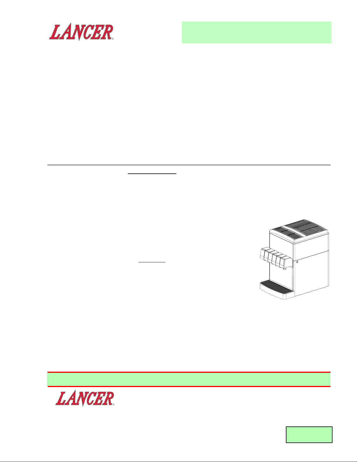
INSTALLATION AND SERVICE MANUAL
FOR
DELTA III DISPENSER
LANCER SERIES 9000
(JUICE DISPENSER)
REV. 10/26/00
P.N. 28-0431/01
This manual supersedes 28-0431, dated 08/27/99
FAX ENGINEERING: • 210-310-7096
"Lancer" is the registered trademark of Lancer • Copyright — 2000 by Lancer, all rights reserved.
Please refer to the Lancer web site (www.lancercorp.com) for
information relating to Lancer Installation and Service Manuals,
Instruction Sheets, Technical Bulletins, Service Bulletins, etc.
6655 LANCER BLVD. • SAN ANTONIO, TEXAS 78219 USA • (210) 310-7000
FAX SALES
• NORTH AMERICA – 210-310-7245 • INTERNATIONAL SALES – 210-310-7242 • CUSTOMER SERVICE – 210-310-7242 •
• LATIN AMERICA – 210-310-7245 • EUROPE – 32-2-755-2399 • PACIFIC – 61-8-8268-1978 •
Page 2

T
ABLE OF CONTENTS
SPECIFICATIONS......................................................................................................................................Cover
TABLE OF CONTENTS ......................................................................................................................................i
DISPENSER INSTALLATION HIGHLIGHTS.....................................................................................................ii
1. INSTALLATION ...........................................................................................................................................1
1.1 RECEIVING .......................................................................................................................................1
1.2 UNPACKING ......................................................................................................................................1
1.3 UNPACKING INSTALLATION KITS ...................................................................................................1
1.4 SELECTING A COUNTER LOCATION .............................................................................................1
1.5 MOUNTING THE DISPENSER..........................................................................................................1
1.6 CONNECTING THE DRAIN...............................................................................................................1
1.7 FILLING UNIT WITH WATER ............................................................................................................2
1.8 CONNECTING TO ELECTRICAL POWER .......................................................................................2
1.9 CONNECTING TO WATER SUPPLY.................................................................................................2
1.10 CONNECTING TO REMOTE BAG-IN-BOX (BIB) SYRUP PUMPS..................................................3
1.11 CONNECTING TO REMOTE PRESSURIZED SYRUP SUPPLY (FIGAL)........................................3
1.12 PURGING THE THE WATER AND SYRUP SYSTEMS ....................................................................3
1.13 ADJUSTING WATER FLOW (LEV®)..................................................................................................3
1.14 ADJUSTING WATER TO SYRUP (RATIO) BRIX (LEV®)..................................................................4
1.15 VOLUMETRIC VALVE ADJUSTMENT...............................................................................................4
2. SCHEDULED MAINTENANCE ...................................................................................................................6
2.1 AS NEEDED.......................................................................................................................................6
2.2 DAILY .................................................................................................................................................6
2.3 WEEKLY.............................................................................................................................................6
2.4 MONTHLY ..........................................................................................................................................6
2.5 EVERY SIX MONTHS........................................................................................................................6
2.6 YEARLY..............................................................................................................................................6
3. DISPENSER CLEANING AND SANITIZING ..............................................................................................6
3.1 GENERAL INFORMATION ................................................................................................................6
3.2 AMBIENT PROCESS.........................................................................................................................7
3.3 ALTERNATE CLEANING AND SANITIZING AGENTS......................................................................7
3.4 VALVES ..............................................................................................................................................8
3.5 CLEANING AND SANITIZING BAG-IN-BOX (BIB) SYSTEMS .......................................................10
3.6 CLEANING AND SANITIZING FIGAL SYSTEMS............................................................................11
4. TROUBLESHOOTING...............................................................................................................................12
4.1 WATER LEAKAGE AROUND NOZZLE ...........................................................................................12
4.2 LEAKAGE BETWEEN UPPER AND LOWER VALVE BODIES.......................................................12
4.3 MISCELLANEOUS LEAKAGE .........................................................................................................12
4.4 INSUFFICIENT WATER FLOW........................................................................................................12
4.5 INSUFFICIENT SYRUP FLOW........................................................................................................12
4.6 ERRATIC RATIO ..............................................................................................................................13
4.7 NO PRODUCT DISPENSED ...........................................................................................................13
4.8 WATER ONLY DISPENSED, NO SYRUP; SYRUP ONLY DISPENSED, NO WATER ...................13
4.9 NO WATER, JUST SYRUP..............................................................................................................13
4.10 VALVE WILL NOT SHUT OFF .........................................................................................................14
4.11 WATER CONTINUALLY OVERFLOWS FROM WATER BATH INTO DRIP TRAY .........................14
4.12 COMPRESSOR STARTS AND CONTINUES TO RUN UNTIL FREEZE UP
AND WILL NOT CUT OFF ...............................................................................................................14
4.13 WARM DRINKS................................................................................................................................14
4.14 COMPRESSOR DOES NOT START (NO HUM), CONDENSER FAN MOTOR
DOES NOT RUN AND NO ICE BANK.............................................................................................14
4.15 COMPRESSOR DOES NOT START (NO HUM), BUT CONDENSER
FAN MOTOR RUNS.........................................................................................................................15
4.16 COMPRESSOR DOES NOT START BUT HUMS ...........................................................................15
4.17 COMPRESSOR STARTS BUT DOES NOT SWITCH OFF START WINDING ...............................15
4.18 COMPRESSOR STARTS AND RUNS A SHORT TIME BUT SHUTS OFF
ON OVERLOAD ...............................................................................................................................15
4.19 COMPRESSOR RUNS NORMALLY, BUT WATER LINE IS FROZEN............................................15
i
Page 3

4.20 COMPRESSOR CYCLES ON AND OFF FREQUENTLY DURING THE INITIAL
AND/OR NORMAL PULLDOWN OPERATIONS .............................................................................15
4.21 CIRCUIT BREAKER TRIPPING.......................................................................................................16
4.22 BIB PUMP DOES NOT OPERATE WHEN DISPENSING VALVE IS OPENED..............................16
4.23 BIB PUMP OPERATED BUT NO FLOW .........................................................................................16
4.24 BIB PUMP CONTINUES TO OPERATE WHEN BAG IS EMPTY ...................................................16
4.25 BIB PUMP FAILS TO RESTART AFTER BAG REPLACEMENT ....................................................16
4.26 BIB PUMP FAILS TO STOP WHEN DISPENSING VALVE IS CLOSED.........................................16
4.27 NO PRODUCT OUT LIGHT.............................................................................................................16
5. ILLUSTRATIONS, PARTS LISTINGS, WIRING DIAGRAMS, AND PLUMBING DIAGRAMS................17
5.1 REFRIGERATION DECK ASSEMBLY ........................................................................................17-18
5.2 CABINET ASSEMBLY .................................................................................................................19-20
5.3 CAGE ASSEMBLY ......................................................................................................................21-22
5.4 CONTROL HOUSING.................................................................................................................23-24
5.5 WATER REGULATOR ASSEMBLY..................................................................................................25
5.6 WIRING DIAGRAM ..........................................................................................................................26
ii
TABLE OF CONTENTS (CONTINUED)
DISPENSER INSTALLATION HIGHLIGHTS
Listed below are seven critical elements which will aid in a successful installation.
1. Fill water bath until water overflows from tank overflow tube.
2 If this dispenser is installed in an area that is susceptible to ±10% variation of the nominal line voltage,
consider installing a surge protector or similar protection device.
3. There is a five (5) minute delay which prevents the compressor and condenser fan from starting until the
delay has lapsed. If electrical current is interrupted, there is always a five (5) minute delay before the
compressor starts.
4. Supply Water Pressure: Minimum - 40 PSIG (2.76 BAR); Maximum - 110 PSIG (7.58 BAR). If pressure is
over 110 PSIG (7.58 BAR), a water pressure regulator must be used.
5. On units with the built in water regulator, the regulator must be removed if inlet water pressure is less than
40 PSIG (2.76 BAR).
6. CO2 Pressure for syrup pumps: Recommend nominal pressure 70 PSIG (4.83 BAR). Pressure may be
reduced to a minimum of 60 PSIG (4.13 BAR) if remote syrup pumps are being used. It may be increased
to a maximum of 80 PSIG (5.52 BAR) for highly viscous syrups.
7. Valve Adjustment: Make sure drink temperature is below 40°F (4.4°C) before adjusting brix.
Page 4

1
1. INSTALLATION
1.1 RECEIVING
Each unit is tested and thoroughly inspected before shipment. At the time of shipment, the carrier
accepts the unit and any claim for damages must be made with the carrier. Upon receiving units
from the delivering carrier, carefully inspect carton for visible indication of damage. If damage exists,
have carrier note the same on the bill of lading and file a claim with the carrier.
1.2 UNPACKING
A. Cut steel band and remove.
B. Remove top portion of carton by lifting up.
C. Remove accessory kit and loose parts from top packaging.
D. Remove top inner carton pad and corners.
E. Lift unit up by plywood shipping base and remove lower portion of carton.
F. Inspect unit for concealed damage. If evident, notify delivering carrier and file a claim against
same.
G. Remove plywood shipping base from unit by moving unit so that one side is off the counter top
or table allowing access to screws on the bottom of the plywood shipping base.
NOTE
If unit is to be transported, it is advisable to leave the unit secured to the plywood base.
H. If unit is to be installed with optional legs, assemble legs to unit by tilting unit. DO NOT LAY
UNIT ON ITS SIDE OR BACK.
1.3 UNPACKING INSTALLATION KITS
A. Inspect kits for concealed damage and if evident, notify delivering carrier and file a claim against
same.
B. Each kit contains a list of the parts and a drawing showing the proper assembly of the parts.
1.4 SELECTING A COUNTER LOCATION
A. Select a location close to a properly grounded electrical outlet and water supply that meet the
requirements as shown in the SPECIFICATIONS (see page iii).
CAUTION
FAILURE TO MAINTAIN SPECIFIED CLEARANCE WILL CAUSE THE COMPRESSOR TO
OVERHEAT AND WILL RESULT IN COMPRESSOR FAILURE.
B. Condenser air is drawn in from the front half of the top of the unit, and discharged out the rear
half of the top of the unit. A minimum of eight (8) inches (203 mm) clearance must be
maintained over the top of the unit to provide for proper air flow and air circulation.
1.5 MOUNTING THE DISPENSER
A. The dispenser is designed to be permanently mounted and sealed to the counter or installed on
four (4) inch legs.
B. When the dispenser is to be permanently bolted to the counter top, seal dispenser base to
counter top with a bead of clear silicone caulk or sealant which provides a smooth and easily
cleanable bond to the counter.
C. For leg mounting, use Lancer leg kit (PN 82-0962).
NOTE
NSF listed units must be sealed to the counter or have four (4) inch legs installed.
1.6 CONNECTING THE DRAIN
A. Remove cup rest. Lift splash plate up and pull out and down on the bottom to remove.
B. Remove the drip tray from the unit and connect the drain tube to the drain fitting located on the
back.
C. Route the drain tube to a suitable drain and replace the unit’s drip tray.
Page 5

2
1.7 FILLING UNIT WITH WATER
A. Remove the bonnet from the unit.
B. Remove the plastic plug (located in the front of the unit’s compressor deck) from the unit’s fill
hole.
C. Using a funnel or tube, fill the water bath compartment with water until it flows out of the
overflow tube into the drip tray.
CAUTION
THE WATER BATH COMPARTMENT MUST BE FILLED WITH WATER BEFORE PLUGGING
IN THE UNIT, OTHERWISE THE COMPRESSOR DECK AND CONDENSER FAN MAY NOT
OPERATE PROPERLY.
D. Replace the plastic plug.
1.8 CONNECTING TO ELECTRICAL POWER
WARNING
THIS UNIT MUST BE PROPERLY ELECTRICALLY GROUNDED TO AVOID POSSIBLE FATAL
ELECTRICAL SHOCK OR SERIOUS INJURY TO THE OPERATOR. THE POWER CORD IS
PROVIDED WITH A THREE PRONG GROUNDED PLUG. IF A THREE-HOLE GROUNDED
ELECTRICAL OUTLET IS NOT AVAILABLE, USE AN APPROVED METHOD TO GROUND THE
UNIT.
DO NOT USE EXTENSION CORDS WITH THIS UNIT. DO NOT “GANG” TOGETHER WITH
OTHER ELECTRICAL DEVICES ON THE SAME OUTLET.
A. Check the dispenser serial number plate for correct electrical requirements of unit. Do not plug
into wall electrical outlet unless the current shown on the serial number plate agrees with local
current available.
B. Route the power supply cord to a grounded electrical outlet of the proper voltage and amperage
rating, and plug in the unit. This will turn on the refrigeration system and allow it to start cooling
while completing the rest of the installation. The agitator motor will start immediately, but the
compressor and fan motor will not start until the five (5) minute delay has elapsed.
1.9 CONNECTING TO WATER SUPPLY
CAUTION
IF THE WATER SOURCE EXCEEDS 110 PSIG (7.58 BAR) A WATER REGULATOR KIT MUST BE
USED TO LIMIT WATER PRESSURE TO 110 PSIG (7.58 BAR). FAILURE TO USE A WATER
REGULATOR WILL RESULT IN IMPROPER PERFORMANCE OF DISPENSER.
A. Using tubing and fittings from the installation kit, connect tubing assembly to water source. DO
NOT CONNECT TO DISPENSER AT THIS TIME.
B. Flush water supply line thoroughly.
NOTE
If the water source is above 110 PSIG (7.58 BAR), cut tubing assembly and install Water
Regulator Kit (PN 18-0253/02) as shown in kit instruction sheet.
A dispenser connected to a water supply system under pressure shall have one or more of the
following: an air gap, a vacuum breaker that conforms to ASSE standards, a backflow
prevention device that conforms to ASSE standards, or another approved method to comply with
NSF standards. Such devices must comply with Federal, State, and local codes. It is the
responsibility of the installer to ensure compliance.
C. Route through hole in counter and through opening behind splash plate and connect to
the water inlet tube with a 21/32 inch Oetiker clamp (PN 07-0438).
D. Leave one (1) foot (305 mm) of extra tubing length below the counter for servicing and moving
the dispenser.
E. Turn on water supply and check for leaks.
F. Using test gauge assembly (PN 22-0138), set regulator at a maximum of 110 PSIG (7.58 BAR).
Page 6
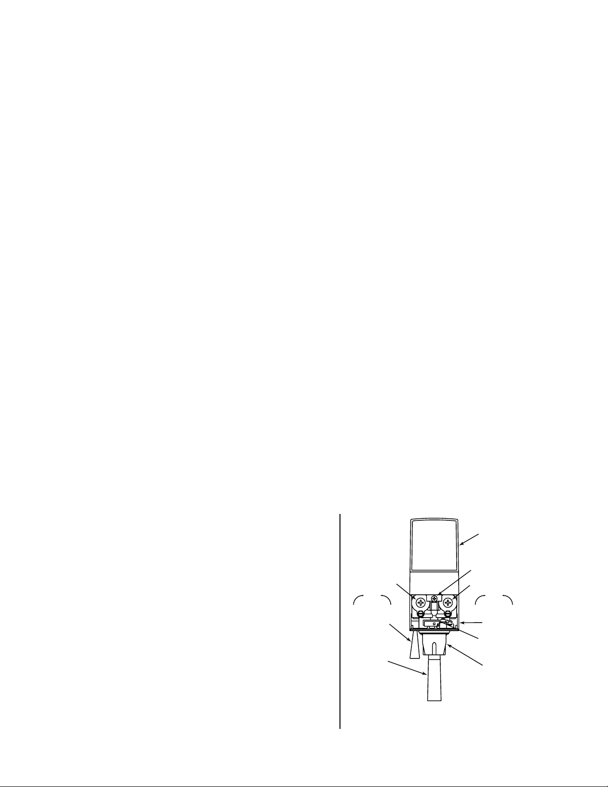
Typical Valve Adjustment, LEV®
Figure 1
3
1.10 CONNECTING TO REMOTE BAG-IN-BOX (BIB) SYRUP PUMPS
A. Connect high pressure CO2 regulator assembly to CO2 cylinder. Use a new CO2 tank washer if
regulator does not have built-in o-ring seal.
B. Place CO2 cylinder in service location (for example, under counter) and secure CO2 cylinder
with a safety chain.
C. Using tubing and fittings from installation kit, connect tubing assembly to tank mount regulator
using flare seal washer (PN 05-0011). Use a back-up wrench to prevent damage to regulator
assembly.
D. Locate the remote BIB, syrup supply and pumps in a convenient location.
E. Attach the syrup supply tubes to the dispenser’s syrup inlet fittings (located behind the splash
plate) using a 21/32 inch (17.0 mm) Oetiker clamp for each syrup flavor.
F. Route the syrup supply tubes to the remote syrup pumps.
G. Complete installation of the remote syrup pump system following the manufacturer’s
instructions.
1.11 CONNECTING TO REMOTE PRESSURIZED SYRUP SUPPLY (FIGAL)
A. Connect high pressure CO2 regulator assembly to CO2 cylinder. Use a new CO2 tank washer if
regulator does not have built-in o-ring seal.
B. Place CO2 cylinder in service location (for example, under counter) and secure CO2 cylinder
with a safety chain.
C. Using tubing and fittings from installation kit connect tubing assembly to tank mount regulator
using flare seal washer (PN 05-0011). Use a back-up wrench to prevent damage to regulator
assembly.
D. Locate the five gallon (figal) syrup containers and the CO2 cylinder and regulator set in a
convenient location.
E. Attach the syrup supply tube assembly to the dispenser’s syrup inlet fittings (located behind the
splash plate) using a 21/32 inch (17.0 mm) Oetiker clamp for each syrup flavor.
F. Route the syrup supply tubes to the figal syrup containers and attach them to the appropriate
syrup flavor.
G. Attach a CO2 supply line from each of the figal syrup containers to the low pressure regulator
and pressurize the containers.
1.12 PURGING THE WATER AND SYRUP SYSTEMS
A. Open a dispensing valve until water and syrup are flowing steadily from the valve.
B. Repeat procedure “A” for each valve.
C. Check all of the unit’s syrup and water connections for leaks and repair if necessary.
D. Replace the unit’s bonnet, splash plate and cup rest.
1.13 ADJUSTING WATER FLOW (LEV®)
A. The water flow can be adjusted between
1.25 oz/sec (37 ml/sec) and 2.50 oz/sec (74 ml/sec)
on all dispensing valves using the following
procedure.
B. The refrigeration unit should have been running for
at least one (1) hour before you attempt to brix the
valves. The drink temperature should be no higher
than 40°F (4.4°C) when the brix is set. This is best
done after the unit has made an ice bank.
C. Slide up ID panel until flow controls are exposed
(see Figure 1).
D. Remove nozzle by twisting counter clockwise and
pulling down.
E. Remove diffuser by pulling down.
F. Install Lancer (yellow) syrup separator
(PN 54-0031) in place of nozzle.
G. Activate dispensing valve to fill separator syrup
tube.
I.D. PANEL
open position)
COVER SCREW
FLOW CONTROL
WATER
DecreaseIncrease
SODA LEVER
(Optional)
CUP LEVER
FLOW CONTROL
MANUFACTURE
SERIES NO.
(Shown in
SYRUP
DecreaseIncrease
COVER
DATE OF
NOZZLE
Page 7
4
H. Hold a Lancer brix cup under the syrup separator and dispense water and syrup into cup for
four (4) seconds. Divide number of ounces (ml) of water in cup by four (4) to determine water
flow rate per second.
I. To obtain the proper flow, use a screwdriver to adjust water flow control (see Figure 1).
J. Repeat process for each valve.
1.14 ADJUSTING WATER TO SYRUP (RATIO) BRIX (LEV®)
A. Hold the Lancer brix cup under the syrup separator and activate valve. Check brix.
B. To obtain the proper brix, use screwdriver to adjust syrup flow control (see Figure 1).
C. Once proper ratio is obtained repeat to verify.
D. Remove syrup separator (PN 54-0031 installed in Section 1.13.F above).
E. Install diffuser and nozzle.
F. Slide down ID panel.
G. Repeat process for each valve.
1.15 VOLUMETRIC VALVE ADJUSTMENT (SEE FIGURE 2)
NOTE
The Volumetric Valve is an optional valve with the Delta III Dispenser.
A. Valve Specifications
1. Finished Drink Flow Rates
3.0 ounces per second (88.7 ml/sec), as shipped
2.25 ounces per second (66.6 ml/sec)
1.5 ounces per second (44.4 ml/sec)
2. Flowing Pressure Requirements
MINIMUM
MAXIMUM
Water 40 psig (2.76 BAR) 110 psig (7.58 BAR)
Syrup 20 psig (1.38 BAR) 70 psig (4.83 BAR)
3. Electrical Requirement
24 VAC, 50/60Hz
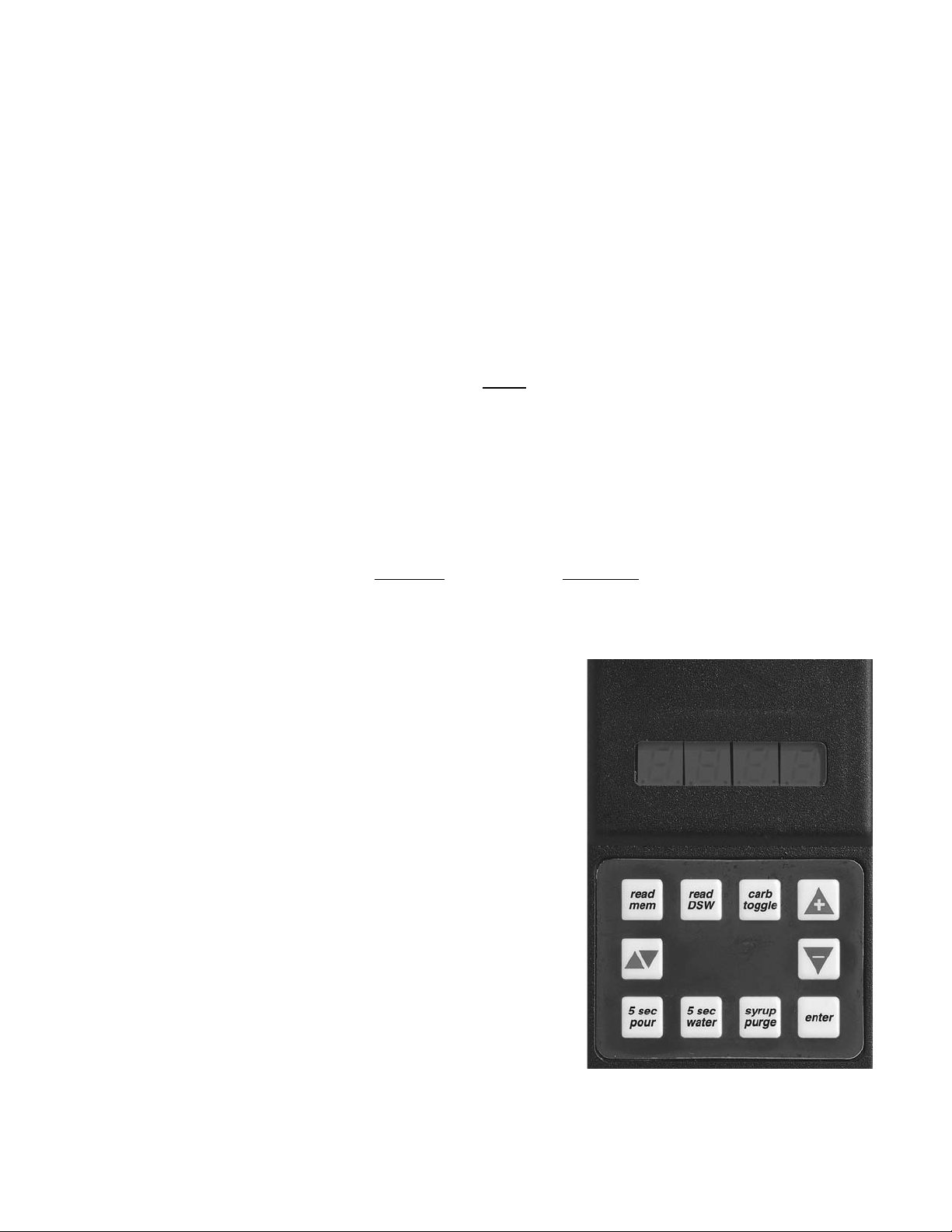
B. Programmer Operating Procedures
1. Connecting
a. Remove the ID panel from the front
of the valve.
b. Insert the programmer's 10-pin
connector into the ID Panel plug on
the front of the circuit board.
c. When properly connected, the
programmer will run a self diagnostic
test. The display will show all "8"s
with the decimal points lighted. After
three (3) seconds, the display indicates the setting of the dip switches.
d. If the programmer does not run its
diagnostic test properly, disconnect
it and try plugging it in again. If the
programmer still fails, replace the
programmer.
Handheld Programmer,
Volumetric Valve
Figure 2
Page 8
5
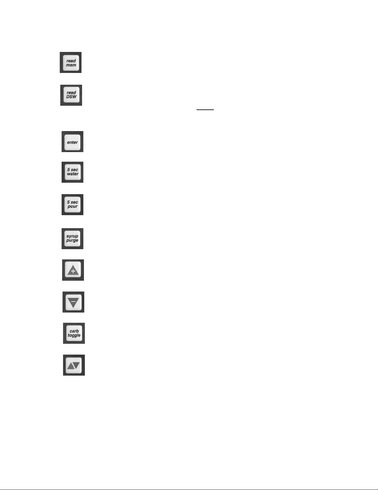
2. Functions
Read Memory:
Press this button to read and display the current settings programmed into the valve
memory (i.e., S/W revision, ratio, and carb/non carb settings).
Read Dip Switches:
Press this button to read the dip switch settings (applies only to valves manufactured
before July 1997).
NOTE
Dip switches were used on some field test valves (refer to 28-0301, 12/20/95).
Write Memory:
Press this button to write the programmer’s displayed ratio and carbonation settings into
the valve’s memory.
Timed 5 Second Water:
Press this button to pour water for five (5) seconds. The programmer will display the
ratio, the counts from the flowmeter, the flow rate in oz/sec, and the flow rate in ml/sec.
Timed 5 Second Pour:
Press this button to dispense a five (5) second pour of water and syrup for ratio testing.
When complete, the programmer displays the ratio, carbonation settings, and total
Flowmeter counts.
Syrup Purge:
Press and release to dispense a six (6) second syrup purge. Continue holding to purge
syrup from system.
Ratio + (Plus):
Pressing this button will increase the ratio number on the display.
Ratio - (Minus):
Pressing this button will decrease the ratio number on the display.
Carb Toggle:
Pressing this button will toggle the carbonation setting from carbonated “C” to plain
water “n” (non-carbonated).
Pour/Stop:
Press this button to manually pour a mixed drink. This button will also stop a timed pour.
Setting the Ratio/Carbonation
1. Connect the programmer to the Valve.
2. Press the “Read Mem” button.
3. Press the “Ratio +” or the “Ratio -” key until the desired ratio is displayed.
4. Verify the drink type. Press “Carb Toggle”to select “C” for carbonated or “n” for
non-carbonated.
5. Press the “Enter” button to program the valve with the setting on the display.
6. Verify Ratio by pressing “Read Mem”.
7. Disconnect the programmer.
Page 9

6
2. SCHEDULED MAINTENANCE
2.1 AS NEEDED
a. Keep dispenser’s exterior surfaces (to include drip tray/cup rest) cleaned with damp, clean cloth.
2.2 DAILY
A. Remove the nozzle and diffuser from each valve and wash them in warm water.
B. Remove the cup rest and wash in warm soapy water.
C. Pour warm soapy water into the drip tray and wipe with a clean cloth.
D. With a clean cloth and warm soapy water, wipe off all of the unit’s exterior surfaces.
E. Replace the cup rest, valve diffusers and valve nozzles.
2.3 WEEKLY
A. Check the flow and brix of each LEV® valve following the brixing instructions given in Sections
1.13 and 1.14.
B. Remove the unit’s bonnet and check the level of water in the water bath. Replenish as required,
and replace the bonnet.
2.4 MONTHLY
A. Unplug the dispenser from its power source.
B. Remove the bonnet and, using a soft brush, clean the dirt from the unit’s condenser.
C. Replace the bonnet. Plug in the unit.
2.5 EVERY SIX (6) MONTHS
A. Clean and sanitize the unit using the appropriate procedures outlined in Section 3.
2.6 YEARLY
A. Clean water bath interior, including evaporator coils and refrigeration components.
B. Clean the entire exterior of the unit.
C. Sanitize syrup lines.
3. DISPENSER CLEANING AND SANITIZING
3.1 GENERAL INFORMATION
A. Lancer equipment (new or reconditioned) is shipped from the factory cleaned and sanitized in
accordance with NSF guidelines. The operator of the equipment must provide continuous
maintenance as required by this manual and/or state and local health department guidelines to
ensure proper operation and sanitation requirements are maintained.
NOTE
The cleaning and sanitizing procedures provided herein pertain to the Lancer equipment
identified by this manual. If other equipment is being cleaned, follow the guidelines established
by the manufacturer for that equipment.
IMPORTANT
Water lines are not to be disconnected during the cleaning and sanitizing of syrup lines to avoid
contamination.
B. Cleaning and sanitizing should be accomplished only by trained personnel. Sanitary gloves are
to be used during cleaning and sanitizing operations. Applicable safety precautions must be
observed. Instruction warnings on the product being used must be followed.
C. Recommended Preparation of Cleaning Solutions.
1. Cleaning solutions (for example, Ivory Liquid, Calgon, etc.) mixed with clean, potable water
at a temperature of 90° to 110° Fahrenheit should be used to clean equipment. The
mixture ratio, using Ivory Liquid, is one (1) ounce of cleanser to two (2) gallons of water.
A minimum of four (4) gallons of cleaning mixture should be prepared.
NOTE
Extended lengths of product lines may require that an additional volume of solution be
prepared.
Page 10

2. Any equivalent cleanser may be used as long as it provides a caustic based,
non-perfumed, easily rinsed mixture containing at least two (2) percent sodium
hydroxide (NaOH).
D. Recommended Preparation of Sanitizing Solutions.
1. Sanitizing solutions should be prepared in accordance with the manufacturer’s written
recommendations and safety guidelines. Follow manufacturer’s requirements so that the
solution provides 200 parts per million (PPM) available chlorine at a temperature of 90°F to
120°F. A minimum of four (4) gallons of sanitizing solution should be prepared.
NOTE
Extended lengths of product lines may require that an additional volume of solution be
prepared.
2. Any sanitizing solution may be used as long as it is prepared in accordance with the
manufacturer’s written recommendations and safety guidelines, and provides 200 parts per
million (PPM) available chlorine.
3.2 AMBIENT PROCESS
A. The ambient process is the most common method for cleaning and sanitizing dispenser
equipment. The detergent should be caustic-based and the sanitizer should be low pH (7.0)
chlorine solution.
B. Disconnect syrup containers and remove product from tubing by purging with carbon dioxide.
C. Rinse the lines and fittings with clean room temperature water to remove all traces of residual
product.
D. Fill lines with a caustic-based (low-sudsing, non-perfumed, and easily rinsed) detergent
solution. The solution should be prepared in accordance with the manufacturers
recommendations, but should be at least 2 percent (2%) sodium hydroxide. Make sure the lines
are completely filled and allow to stand for at least 10 minutes.
E. Flush the detergent solution from the lines with clean water. Continue rinsing until testing with
phenolphthalein shows that the rinse water is free of residual detergent.
F. Fill the lines with a low pH (7.0) chlorine solution containing at least 50 PPM (50 mg/L) chlorine.
Make sure that lines are completely filled and allow to stand for 10 minutes.
G. Reconnect syrup containers and ready Unit for operation.
H. Draw drinks to refill lines and flush the chlorine solution from the dispenser.
NOTE
Please note that a fresh water rinse cannot follow sanitization of equipment. Purge only with
the end use product. This is an NSF requirement.
I. Taste the beverage to verify that there is no off taste.
3.3 ALTERNATE CLEANING AND SANITIZING AGENTS
The above approach to cleaning and sanitizing is strongly recommended. However, the Division
Quality Assurance Manager may approve the following cleaning and sanitizing agents.
A. Chlorinated alkaline detergents. These compounds may be used as the cleaning agent, but
may not be used as combined cleaner/sanitizer.
B. Iodophors may be substituted for chlorine as the sanitizing agent.
CAUTION
IODOPHORS AND QUATERNARY AMMONIUM COMPOUNDS (QUATS) ARE BROAD CLASSES
OF COMPOUNDS. SOME MEMBERS OF EACH GROUP CAN CAUSE SERIOUS PROBLEMS
WITH FOAMING, DISTORTION OR DISCOLORATION OF POLYMERIC PARTS, POOR
RINSIBILITY, AND OFF-TASTE. THE RINSIBILITY AND OFF-TASTE PROBLEMS HAVE BEEN
ESPECIALLY PREVALENT WITH QUATS. BECAUSE OF THE POTENTIAL PROBLEMS,
APPROVAL MUST BE GRANTED BY THE DIVISION QUALITY ASSURANCE MANAGER TO
SPECIFIC COMPOUNDS. THIS APPROVAL SHOULD BE BASED UPON TESTING IN THE
LABORATORY.
C. Quaternary ammonium compounds may be used as a combined cleaner-sanitizer but are
generally not recommended. These compounds are not to be utilized at concentrations
7
Page 11

exceeding 200 PPM (200 mg/L), or that concentration specified in local regulations, which ever
is lower.
3.4 VALVES
A. LEV
® Valves may be cleaned and sanitized (see preparation in Sections 3.1 or 3.2) in the same
manner.
NOTE
See Lancer Installation and Service Manual 28-0027/03 for complete information on the LEV®.
W
ARNING
FLUSH SANITIZING SOLUTION FROM SYRUP SYSTEMS AS INSTRUCTED. RESIDUAL
SANITIZING SOLUTION LEFT IN SYSTEM COULD CREATE HEALTH HAZARD.
1. Remove cover and disconnect power so the valve will not be activated during the cleaning
procedure. Remove nozzle and diffuser. Wash these parts in cleaning solution; then
immerse them in a bath of sanitizing solution for 15 minutes.
NOTE
Please note that a fresh water rinse cannot follow sanitization of equipment. Purge only with
the end use product. This is an NSF requirement.
2. Visually inspect around nozzle area for syrup residue. This area may be cleaned with warm
water and cloth or with the nozzle brush supplied. Wipe off dispensing lever (if valve is so
equipped).
3. Wearing sanitary gloves, remove, drain and air dry the nozzle and diffuser.
4. Wearing sanitary gloves, replace diffuser, twist nozzle in place.
5 Connect power and replace cover. Valve is ready for operation.
B. Volumetric Valve Cleaning and Sanitizing Procedures
NOTE
The Volumetric Valve is an optional valve with the Delta III Dispenser. See Lancer
Maintenance Manual 28-0301/02 for complete information on the Volumetric Valve.
8
Nozzle/Diffuser
Figure 3
1. Daily Nozzle/Diffuser Cleaning (See Figure 3)
Use the following procedures to clean the nozzle, and the
diffuser assembly, each day:
a. Remove nozzle by twisting it counter-clockwise and
pulling it down.
b. Pull the diffuser assembly down to remove it from the
valve.
c. Wash the nozzle and diffuser with warm water.
d. If needed, apply 111 lubricant to the o-ring on the
diffuser assembly. Then, carefully press it into the
diffuser mounting area on the underside of the valve.
e. Make certain the nozzle o-ring, is in place around the
nozzle mounting area on the valve. If necessary, slide
a new nozzle o-ring onto the nozzle mounting area.
f. Install the nozzle by inserting it into the bottom plate
and twisting it clockwise to lock it in place.
2. Monthly Nozzle/Diffuser Sanitizing
Use the following procedures to clean and sanitize the nozzle and the diffuser assembly
once a month.
a. Cleaning Solution
(1) Prepare a caustic-based (low sudsing, non-perfumed, and easily rinsed)
detergent solution and clean, potable water at a temperature of 90° to 110°F. The
Diffuser
Assembly
Nozzle
Page 12

cleaning solution should be 2% sodium hydroxide.
b. Sanitizing Solution
(1) Prepare a chlorine solution (less than pH 7.0) containing 50 PPM available chlorine
with clean, potable water at a temperature of 90° to 110°F. Any sanitizing solution
may be used as long as it is prepared in accordance with the manufacturer’s
written recommendations and safety guidelines, and provides 50 PPM available
chlorine.
c. Cleaning Procedure
CAUTION
BE CAREFUL NOT TO GET SANITIZING SOLUTION ON THE CIRCUIT BOARD.
(1) Disconnect power, so the valve will not be inadvertently activated while cleaning.
(2) Remove nozzle by twisting it counter-clockwise and pulling it down.
(3) Pull the diffuser assembly down to remove it from the valve.
(4) Wash the nozzle and diffuser with the cleaning solution.
(5) Immerse the nozzle and diffuser in a bath of the sanitizing solution for 15 minutes.
(6) While the parts are in the sanitizing solution, visually inspect around the nozzle
mounting area on the valve for syrup residue. Using a cloth or nozzle brush and
warm water, clean this area.
(7) Wipe off the dispensing lever (if so equipped) and any other areas that may have
been splashed by syrup.
(8) Wearing sanitary gloves, remove, drain, and air dry the nozzle and diffuser.
(9) Wearing sanitary gloves, carefully press the diffuser into the mounting area on the
underside of the valve.
(10) Make certain the nozzle o-ring, is in place around the nozzle mounting area on the
valve. If necessary, slide a new nozzle o-ring onto the nozzle mounting area.
(Wear sanitary gloves while handling the o-ring.)
(11) Wearing sanitary gloves, install the nozzle by inserting it into the bottom plate and
twisting it clockwise to lock it in place.
(12) Connect power and replace cover. Valve is ready for operation.
(13) Draw drinks to flush residual sanitizing solution. Taste the beverage to verify that
there is no off taste. If an off taste is found, additional flushing may be required.
NOTE
Please note that a fresh water rinse cannot follow sanitization of equipment. Purge
only with the end use product. This is an NSF requirement.
3. Valve and System Sanitizing
a. The complete valve and dispenser system must be sanitized during initial installation.
Follow the manufacturer’s instructions when scheduling and conducting dispenser
sanitizing. The valve must be sanitized once every two weeks. The valve may remain
on the dispensing tower during the sanitizing process.
b. For syrup side line priming, and cleaning and sanitization procedures, refer to the Syrup
Purge Plug (Lancer PN 52-1912) in Section 3.4.C which follows.
9
Syrup Purge Plug, Volumetric Valve
Figure 4
C. Syrup Purge Plug (See Figure 4)
1. The Syrup Purge Plug (PN 52-1912), places the valve
in continuous syrup side operation. The targeted
uses for the purge plug consist of priming the syrup
line on an initial Volumetric Valve install, and for
cleaning and sanitization of the syrup side of the dispensing unit.
2. Operation of the syrup purge plug is as follows:
NOTE
With a standard 75 VA transformer, up to six (6)
Volumetric Valves can be operated in the syrup purge
mode simultaneously.
SYRUP PURGE
52-1912
Page 13

10
a. Turn off electrical power to all valves.
b. Install syrup purge plugs into the valve or valves to be primed or sanitized. The syrup
purge plug installs in the ten-pin connector of the Volumetric Valve circuit board.
c. Turn on electrical power to the valves. At this time, the syrup side of the valves will
begin continuous operation.
d. When through with the priming or sanitization operation, syrup purge operation can be
stopped in either of two ways:
Method 1: Turn off electrical power to all valves, remove syrup purge plugs from the
valves. Turn on electrical power to all valves. Tap valve lever or push button to ensure
proper operation of all valves.
Method 2: Remove syrup purge plug from the valves while they are in purge operation.
In this case, the valve may continue in the purge mode for up to six (6) seconds after
removal of the plug (this is normal). Tap valve lever or push button to ensure proper
operation of all valves.
3.5 CLEANING AND SANITIZING BAG-IN-BOX (BIB) SYSTEMS
A. Disconnect syrup quick disconnect coupling from syrup packages and connect coupling to a bag
valve removed from an empty Bag-in-Box package.
B. Place end of syrup inlet line, with bag valve attached, in a clean container filled with clean,
potable, room temperature water.
C. Place waste container under applicable dispensing valve. Activate valve until water is
dispensed. Flush and rinse line and fittings for a minimum of 60 seconds to remove all traces
of residual product.
NOTE
Extended lengths of product lines may require additional time for flushing and rinsing lines.
D. Prepare cleaning solution as described in Section 3.1.C above. Place end of syrup inlet line in
container filled with cleaning solution.
E. Place waste container under applicable dispensing valve. Activate valve and draw cleaning
solution through lines for a minimum of 60 seconds. This will ensure line is flushed and filled
with cleaning solution. Allow line to stand for at least 30 minutes.
F. Place end of syrup inlet line in a clean container filled with clean, potable, water at a
temperature of 90° to 110°F.
G. Place waste container under applicable dispensing valve. Activate valve to flush and rinse line
and fittings for a minimum of 60 seconds to remove all traces of cleaning solution. Continue
rinsing until testing with phenolpthalein shows that the rinse water is free of residual detergent.
H. Prepare sanitizing solution as described in Section 3.1.D above. Place end of syrup inlet line
in container filled with sanitizing solution which has been prepared.
I. Activate valve and draw sanitizing solution through line for a minimum of 60 seconds. This will
ensure line is flushed and filled with sanitizing solution. Allow line to stand for at least
30 minutes.
J. Remove bag valve from quick disconnect coupling and reconnect syrup inlet line to syrup
package. Ready unit for operation.
W
ARNING
FLUSH SANITIZING SOLUTION FROM SYRUP SYSTEMS AS INSTRUCTED. RESIDUAL
SANITIZING SOLUTION LEFT IN SYSTEM COULD CREATE HEALTH HAZARD.
K. Draw drinks and refill lines with end product to flush sanitizing solution from the dispenser.
NOTE
Please note that a fresh water rinse cannot follow sanitization of equipment. Purge only with
the end use product. This is an NSF requirement.
L. Test dispenser in normal manner for proper operation. Taste dispensed product to ensure there
is no off-taste. If off-taste is found, additional flushing of syrup system may be required.
M. Repeat cleaning, rinsing, and sanitizing procedures for each valve circuit.
Page 14

3.6 CLEANING AND SANITIZING FIGAL SYSTEMS
A. Remove quick disconnect from syrup tank.
CAUTION
DO NOT USE A WIRE BRUSH TO CLEAN VALVES.
B. Using a clean plastic bristle brush and a detergent soap solution prepared in accordance with
the instructions in Section 3.1.C, scrub both valves of the disconnect. Rinse with clean, potable
water.
C. Using a mechanical spray bottle and a sanitizing solution prepared in accordance with the
instructions in Section 3.1.D, spray both halves of the quick disconnects. Allow to air dry.
NOTE
Please note that a fresh water rinse cannot follow sanitization of equipment. Purge only with
the end use product. This is an NSF requirement.
D. Connect syrup line to a syrup tank filled with clean, potable, room temperature water. Connect
CO2
supply hose to tank and pressurize.
E. Place waste container under applicable dispensing valve. Activate valve until water is
dispensed. Flush and rinse line and fittings for a minimum of 60 seconds to remove all traces
of residual product.
NOTE
Extended lengths of product lines may require additional time for flushing and rinsing lines.
W
ARNING
TO AVOID POSSIBLE PERSONAL INJURY OR PROPERTY DAMAGE, DO NOT ATTEMPT
TO REMOVE SYRUP TANK COVER UNTIL CO
2 PRESSURE HAS BEEN RELEASED FROM
TANK.
F. Disconnect CO2supply hose from the water filled syrup tank.
G. Prepare cleaning solution as described in Section 3.1.C above. Fill a tank with cleaning
solution. Connect syrup line to the tank. Connect CO
2 supply hose to tank and pressurize.
H. Place waste container under applicable dispensing valve. Activate valve and draw cleaning
solution through lines for a minimum of 60 seconds. This will ensure line is flushed and filled
with cleaning solution. Allow line to stand for at least 30 minutes.
NOTE
Extended lengths of product lines may require additional time for flushing and filling lines.
I. Disconnect CO2 supply hose from the tank.
J. Connect syrup line to a tank filled with clean, potable, water at a temperature of 90° to 110°F.
Connect CO
2
supply hose to tank and pressurize.
K. Place waste container under applicable dispensing valve. Activate valve to flush and rinse line
and fittings for a minimum of 60 seconds to remove all traces of cleaning solution. Continue
rinsing until testing with phenolpthalein shows that the rinse water is free of residual detergent.
L. Disconnect CO2 supply hose from the tank.
M. Fill a tank with sanitizing solution prepared as described in Section 3.1.D above. Connect syrup
line to the tank. Connect CO
2 supply hose to tank and pressurize.
N. Remove dispensing valve nozzle (twist and pull down) and pull out center mixing baffle. Using
a plastic bristle brush and detergent soap solution, scrub the nozzle, mixing baffle, bottom of
dispensing valve, and cup lever. Rinse with clean water.
O. Reassemble mixing baffle and nozzle.
WARNING
FLUSH SANITIZING SOLUTION FROM SYRUP SYSTEMS AS INSTRUCTED. RESIDUAL
SANITIZING SOLUTION LEFT IN SYSTEM COULD CREATE HEALTH HAZARD.
P. Place waste container under applicable dispensing valve. Activate valve and draw sanitizing
solution through line for a minimum of 60 seconds. This will ensure line is flushed and filled with
sanitizing solution. Allow line to stand for at least 30 minutes.
11
Page 15

12
Q. Disconnect CO2 supply hose from the tank.
R. Reconnect syrup lines to syrup containers (for example, quick disconnects, figal containers, etc.)
and ready unit for operation.
S. Draw drinks and refill lines with end product to flush sanitizing solution from the dispenser.
NOTE
Please note that a fresh water rinse cannot follow sanitization of equipment. Purge only with the
end use product. This is an NSF requirement.
T. Test dispenser in normal manner for proper operation. Taste dispensed product to ensure there
is no off-taste. If off-taste is found, additional flushing of syrup system may be required.
U. Repeat cleaning, rinsing, and sanitizing procedures for each valve/syrup circuit.
V. Clean exterior of unit as instructed in Section 2.1.
W. Using a spray bottle of sanitizing solution, spray the underside of all dispenser valves, valve
spouts and cup levers. Allow to air dry.
NOTE
Thoroughly rinse inside and outside of syrup tank that was used for sanitizing solution with plain
water to remove all solution residue.
4. TROUBLESHOOTING
NOTE
See Lancer Installation and Service Manual 28-0027/03 for complete troubleshooting
information for LEV® valves and/or Lancer Maintenance Manual 28-0301/02 for complete
troubleshooting information for the Volumetric Valve.
TROUBLE
CAUSE REMEDY
4.1 Water leakage around A. Damaged or improperly A. If damaged, replace. If improperly
nozzle. installed o-ring above diffuser. installed, adjust.
4.2 Leakage between upper A. Gap between upper and A. Tighten all six (6) retaining screws.
and lower valve bodies. lower valve bodies.
B. Worn or damaged paddle B. Replace paddle arm assemblies.
arm assemblies.
4.3 Miscellaneous leakage. A. Gap between parts. A. Tighten appropriate retaining
screws.
B. Damaged or improperly B. Replace or adjust appropriate
installed o-rings. o-rings.
4.4 Insufficient water flow. A. Insufficient incoming supply A. Verify incoming supply water
water pressure. pressure is a minimum of 40 PSI.
B. Shutoff on mounting block B. Open shutoff fully.
not fully open.
C. Foreign debris in water flow C. Remove water flow control from
control. upper body and clean out any
foreign material to ensure smooth
free spool movement.
4.5 Insufficient syrup flow. A. Insufficient CO2 pressure to A. Adjust CO2 pressure to 80 PSI
BIB pumps. (minimum 70 PSI) for BIB pumps.
B. Shutoff on mounting block B. Open shutoff fully.
not fully open.
C. Foreign debris in syrup flow C. Remove syrup flow control from
control (LEV® valves only). upper body and clean out any
foreign material to ensure smooth
free spool movement.
Page 16

4.6 Erratic ratio. A. Incoming water and/or syrup A. Check pressure and adjust.
supply not at minimum
flowing pressure.
B. Foreign debris in water and/or B. Remove flow controls from upper
syrup flow controls (LEV® body clean out any foreign
valves only). material to ensure smooth free
spool movement.
4.7 No product dispensed. A. Water and syrup shutoffs on A. Open shutoffs fully.
mounting block not fully open.
B. The key switch on an electric B. Turn key switch to ON position.
valve is in the OFF position.
C. Cup lever arm or ID panel C. Repair.
actuator on electric valve is
not actuating the switch.
D. Electric current not reaching D. Check electric current supplied
electric valve. to valve. If current is adequate,
check solenoid coil and switch,
and replace if necessary.
E. Improper or inadequate E. Remove valve from mounting block
water or syrup supply. and open shutoffs slightly and
check water and syrup supply.
If no supply, check dispenser for
freeze-up or other problems.
F. Transformer failure. F. Reset transformer circuit breaker.
If breaker pops again refer to
Section 4.21.
4.8 Water only dispensed, A. Water or syrup shutoff on A. Open shutoff fully.
no syrup; or syrup only mounting block not fully open.
dispensed, no water. B. Improper or inadequate B. Remove valve from mounting block
water or syrup supply. and open shutoffs slightly and
check water and syrup supply. If
no supply, check dispenser for
freeze-up or other problems.
Ensure BIB connection is engaged.
C. BIB supply too far from C. Check that BIB supply is within six
dispenser. (6) feet of the dispenser.
D. CO
2 pressure too low to D. Check the CO2 pressure to the
syrup pumps. pump manifold to ensure it is
between 60 and 80 PSI.
E. Stalled or inoperative BIB E. Check CO2 pressure and/or
pump. replace pump.
F. Kinked line. F. Remove kink or replace line.
4.9 No water, just syrup. A. Low level. A. Add water until it flows
from over flow tube.
B. Unit not level. B. Level unit and add water.
C. Syrup in water bath. C. Melt ice bank and remove all
water. Refill. Locate possible
syrup leak area and repair.
D. Water cage is out of position. D. Reposition water cage.
E. PCB relay sticking. E. Check continuity of compressor
relay. Compressor should
time-out in five (5) minutes.
F. Refrigerant leak. F. Find leak and recharge unit (if unit
is not frozen).
G. PCB malfunctioning. G. Replace PCB.
TROUBLE
CAUSE REMEDY
13
Page 17

4.10 Valve will not shut off. A. Cup lever may be sticking or A. Correct or replace lever.
binding.
B. Switch not actuating freely. B. Check switch for free actuation.
C. Solenoid armature not C. Replace defective armature or
returning to bottom position. spring.
4.11 Water continually A. Loose water connection(s). A. Tighten water connections.
overflows from water B. Flare seal washer leaks. B. Replace flare seal washer.
bath into drip tray. C. Faulty water coil. C. Replace water coil.
4.12 Compressor starts and A. PCB malfunctioning or faulty A. Disconnect ice band probe from
continues to run until ice bank probe. PCB.
freeze up and will not 1. If compressor continues to run,
cut off. replace PCB.
2. If compressor stops, replace
ice bank probe.
B. Ice bank probe positioned B. Check positioning of ice bank
improperly. probe, and replace if needed.
C. Ice bank probe shorted to ground. C. Replace ice bank probe.
4.13 Warm drinks. A. Restricted airflow. A. Check clearances around sides,
top, and inlet of unit. Remove
objects blocking airflow through
grill.
B. Dispenser connected to B. Switch to cold water supply.
hot water supply.
C. Refrigeration system not C. Refer to 4.14 - 4.18.
running.
D. Refrigerant leak. D. Repair and recharge.
E. Condenser fan motor not E. Replace condenser fan motor.
working.
F. Dirty condenser. F. Clean condenser.
G. Dispenser capacity G. Add pre-cooler or replace with
exceeded. larger dispenser.
4.14 Compressor does not A. There is a five (5) minute A. Allow for five (5) minute delay to
start (no hum), compressor and condenser lapse.
condenser fan motor fan delay.
does not run and B. Ice bank probe not completely B. Fill water reservoir until water flows
no ice bank. submerged. from overflow tube.
C. Circuit breaker or fuse tripped. C. Reset breaker or replace fuse. If
problem persists:
1. Determine reason and correct.
2. Electrical circuit overloaded;
switch to another circuit.
D. Inadequate voltage. D. Measure voltage across common
and run terminal on compressor.
Voltage must not drop below 90%
of rated voltage.
E. PCB malfunctioning. E. Replace PCB assembly.
F. Incorrect wiring. F. Refer to wiring diagram and
correct.
G. Faulty ice bank probe. G. Replace ice bank probe.
H. Transformer failure. H. Reset transformer circuit breaker. If
breaker trips again, refer to 4.23.
I. Ice bank probe not connected I. Connect ice bank probe to PCB.
properly to PCB.
14
TROUBLE
CAUSE REMEDY
Page 18

4.15 Compressor does not A. Compressor relay or overload A. Replace compressor relay or
start (no hum), but malfunctioning. overload.
condenser fan motor B. Inadequate voltage. B. Measure voltage across common
runs. and run terminal on compressor.
Voltage must not drop below 90%
of rated voltage.
C. Incorrect wiring. C. Refer to wiring diagram and
correct.
D. Compressor malfunctioning. D. Replace compressor.
4.16 Compressor does not A. Inadequate voltage. A. Measure voltage across common
start but hums. and run terminal on compressor.
Voltage must not drop below 90%
of rated voltage.
B. Incorrect wiring. B. Refer to wiring diagram and
correct.
C. Starting relay malfunctioning. C. Replace starting relay. Be sure to
use correct relay. Failure to use
correct relay will cause compressor
failure.
D. Compressor malfunctioning. D. Replace compressor or deck.
4.17 Compressor starts but A. Inadequate voltage. A. Measure voltage across common
does not switch off start and run terminal on compressor.
winding (will run for only B. Incorrect wiring. B. Refer to wiring diagram and correct.
a few seconds before C. Starting relay malfunctioning. C. Replace starting relay. Be sure to
internal overload use correct relay. Failure to use
switches compressor correct relay will cause compressor
off). failure.
4.18 Compressor starts and A. Dirty condenser. A. Clean the condenser.
runs a short time but B. Insufficient or blocked air flow. B. Remove all obstructions and allow
shuts off on overload. for minimum clearances of eight (8)
inches (203 mm) over top.
C. Inadequate voltage. C. Measure voltage across common
and run terminal on compressor.
Voltage must not drop below 90%
of rated voltage.
D. Incorrect wiring. D. Refer to wiring diagram and correct.
E. Defective condenser fan motor. E. Replace condenser fan motor.
F. Refrigerant leak. F. Repair and recharge.
G. Compressor malfunctioning. G. Replace compressor.
4.19 Compressor runs A. Low water level in water bath. A. Add water to water bath until water
normally, but water line runs out of overflow into drip tray.
is frozen. B. Syrup in water bath. B. Drain water from water bath and
refill with clean water.
C. Water cage is out of position. C. Reposition water cage.
D. Low refrigerant charge/slow D. Find and repair leak. Recharge
refrigerant leak. system.
4.20 Compressor cycles on A. PCB malfunctioning. A. Replace PCB assembly.
and off frequently during B. Defective probe. B. Replace probe.
the initial pulldown
and/or normal
operations.
TROUBLE CAUSE
REMEDY
15
Page 19

4.21 Circuit breaker tripping. A. Valve wire harness shorted A. Detect short by disconnecting input
to itself or to faucet plate. fast-on (female spade) to keylock
and single pin connector. Restore
power. If breaker doesn’t trip, then
valve wire harness is shorted If
OK, re-connect.
B. PCB is bad. B. Detect short by disconnecting J1
connector (24 VAC input) from
PCB. Restore power, if breaker
doesn’t trip. Then replace PCB. If
breaker does trip, then PCB is OK.
Reconnect J1 connector.
C. Secondary wire harness C. If it does not trip, locate short in
is bad. secondary harness between
transformer, PCB and valve wire
harness.
D. Transformer failure. D. Detect short by disconnecting both
transformer fastons and restore
power. If breaker does trip, replace
transformer.
4.22 BIB pump does not A. Out of CO
2
, CO2 not turned A. Replace CO
2 supply, turn on CO2
operate when on, or low CO
2 pressure to supply, or adjust CO
2 pressure to
dispensing valve is syrup pumps. 70-80 PSI.
opened. B. Out of syrup. B. Replace syrup supply.
C. BIB connector not tight. C. Fasten connector tightly.
D. Kinks in syrup or gas lines. D. Straighten or replace lines.
4.23 BIB pump operated but A. Leak in syrup inlet or outlet A. Replace line.
no flow. line.
B. Defective BIB pump check B. Replace BIB pump.
valve.
4.24 BIB pump continues to A. Leak in suction line. A. Replace line.
operate when bag is B. Leaking o-ring on pump inlet B. Replace o-ring.
empty. fitting.
4.25 BIB pump fails to restart A. BIB connector not on tight. A. Tighten BIB connector.
after bag replacement. B. BIB connector is stopped up. B. Clean out or replace BIB connector.
C. Kinks in syrup line. C. Straighten or replace line.
4.26 BIB pump fails to stop A. Leak in discharge line or A. Repair or replace discharge line.
when dispensing valve fittings.
is closed. B. Empty BIB. B. Replace BIB.
C. Air leak on inlet line or bag C. Repair or replace.
connector.
4.27 No product out light. A. Burned-out lamp. A. Replace lamp.
B. Faulty wiring or pressure B. Repair or replace.
switch in product line.
NOTES:
TROUBLE CAUSE
REMEDY
16
Page 20

17
5. ILLUSTRATIONS, PARTS LISTINGS, WIRING DIAGRAMS, AND PLUMBING DIAGRAMS
5.1 REFRIGERATION DECK ASSEMBLY
12
11
29
20
30
26
20E
20A
20C
20D
20B
44
27
12
16
FROM
EVAPORATOR
20F
23
10
28
41
42
22
43
48
15
8
18
1
5
45
9
17A
17B
14
17C
LINE
LOAD
17F
7
17E
17D
17G
6
17
2
21
40
40A
40B
12
19
3
39A
39G
4
39
39E
39B
39C
3
39F
39D
40C
12
38
12
37
31
32
24
25
36
NOTE: ITEM 13
NOT USED
35
32
34
33
34
33
Page 21

ITEM PART NO. DESCRIPTION
- 82-2768 Deck Assy, Refrigeration,
115V/60Hz
1 51-5107/01 Deck Plate, Sub-Assy
2 50-0200/01 Insulation, Deck Plate
3 04-0063 Washer, Flat, 1/4”
4 89-0014 Hole Cover
5 82-2494 Evaporator Assy
6 52-1773 Probe Assy
7 04-0394 Screw, 6 - 32 X .500”
8 51-0068 Handle
9 04-0574 Washer, Lock, 5/16”
10 52-0900/02 Control Housing Assy
11 06-2221 Label, Wiring Diagram
12 04-0504 Screw, 8 - 18 X .375”
R 13 Not Used
14 52-1209 Lead Assy, Ground
15 02-0041 Seal
16 25-0047 Transformer, 75VA, 24V,
115V/60Hz
17 82-2558 Agitator Assy, 115V/60Hz
17a 05-0424/01 Propeller, 2.625” Diameter
17b 91-0119 Motor, Agitator, 115V/60Hz
17c 06-0634 Label, 115V/60Hz, 25W
17d 04-0059 Screw, 8 - 36 X .375”
17e 30-5113/01 Bracket, Agitator Motor
17f 02-0032 Washer, Rubber
17g 05-1437 Propeller, Water
18 02-0040 Seal, Extrusion
19 04-0032 Nut, Lock, 1/4” - 20
20 83-0033 Compressor Assy, 1/3 hp,
115V/60Hz (includes items
listed below)
20a 83-0033-01 Compressor, 1/3 hp,
115V/60Hz
20b 04-1010 Screw, Brass, 6 - 32 X 0.250”
R 20c 12-0339 Overload
20d 12-0005 Relay
20e 13-0066 Cover, Terminal
20f 03-0040 Bale Strap
21 02-0114 Grommet, Compressor
22 04-0537 Washer, Compressor
23 03-0150 Clip, Retainer, Compressor
24 47-0344 Tube, Process
25 47-0718 Tube, Compressor Discharge
26 47-0724 Tube, Return Line
27 51-0061 Accumulator
28 50-0211 Boot
29 50-0205 Insulation
30 50-0159 Insulation
31 23-0985 Condenser
32 50-0201 Baffle, Rubber
33 30-5112 Retainer Strip
34 04-0518 Rivet, 0.125" X 0.328"
35 30-5867 Handle/Air Shield
36 30-5865 Fan Shroud, Upper
37 50-0249 Insulation, Strip
38 30-5866 Fan Shroud, Lower
R 39 52-2140 Fan Motor Assy, 115V/60Hz
R 39a 91-0007 Fan Motor, 115V/60Hz
39b 07-0354 Fan Blade
39c 04-0060 Nut, Flat
39d 30-5864 Bracket, Fan Motor
39e 02-0033 Silencer, Fan Blade
39f 04-0059 Screw, 8 - 36 X 0.375"
39g 06-0433/01 Label, 115V/60Hz, 9W
40 23-0765 Dryer Cap Assy
40a 23-0982 Dryer Cap
40b 47-0344 Tube, Process
40c 47-0698 Tube, Condenser, Out
41 52-2008 Harness Assembly, Transformer
42 04-0110 Nut, 8-32
43 04-0576 Washer, Lock, Internal Tooth
44 06-0430 Label, 115 V/60 Hz, 1/3 HP
45 06-0877 Label, Ground
- 11-0018 Wire Tie
- 15-0012 Duct Tape
- 15-0011 Adhesive, Insulation
R - 95-0177 Refrigerant, R-134a, 6.50 Ounces
- 96-0004 Solder, 60/40
- 96-0003 Brazing Alloy
R -- 52-2027 Harness Assy, Ground, PCB
R in the margin indicates change or revision
18
5.1 REFRIGERATION DECK ASSEMBLY (CONTINUED)
ITEM PART NO. DESCRIPTION
Page 22

5.2 CABINET ASSEMBLY
19
36
35
40
39
38
42
37
16
15
34
WATER BATH FILL HOLE
FILL WATER BATH UNTIL
-IMPORTANT-
WATER FLOWS FROM
TANK OVERFLOW TUBE.
33
29
30
32
29
28
31
3
4
5
6
7
8
12
1
2
9
18
41
26
20
9
27
9
25
24
11
19
17
23
14
13
10
21
22
9
22
9
23
Page 23

20
5.2 CABINET ASSEMBLY (CONTINUED)
ITEM PART NO.
DESCRIPTION
- 82-2551 Cabinet Assy
R 1 51-5629/02 Wrapper Assy
R 2 30-7353/02 Front Support, SS
R 3 52-1214 Harness Assy, 6 Valve, (Requires
6 each; Items 5 & 6)
R 4 30-5125 Faucet Plate, 6 Valve
5 13-0005 Bushing
6 11-0015 Connector, Housing, 2-Pin
7 04-0443 Screw, 10 - 24 x 0.375”, Countersink
8 04-0074 Nut, Clip, 10 - 24
9 04-0504 Screw, 8 - 18 x 0.375”, with Washer
10 08-0004 Tubing, Tygon, 5/16” ID
11 06-0851 Label, Overflow
12 03-0302 Clip, Drain Hose
13 04-0077 Screw, 4 - 20 x 0.250”
14 03-0062 Clip, Overflow Tube
15 30-0319 Splash Plate
16 05-1585 Cup Rest, Plastic
17 05-1657 Drip Tray
R 18 30-7533/02 Bracket, Drip Tray, Right
R 19 30-7534/02 Bracket, Drip Tray, Left
20 04-0545 Screw, 8 - 16 x 0.750”
21 30-7358 Plate, Tank, Bottom
R 22 30-5221/02 Bracket, Leg
23 81-0112 Leg, Plastic
R 24 07-0405 Plug, Key Switch (Optional)
25 12-0097 Key Switch (Includes Nut)
26 06-0881 Label, Key Switch
27 07-0347 Plate, Cover
28 REF Tank Assy
R - 42-0057/01 Tank Assy
29 50-0151 Insulation, Tank, Side
30 50-0150 Insulation, Tank, Back
31 50-0248 Insulation, Tank, Front
R 32 50-0254/01 Insulation, Cover Plate, Blank
R 33 30-5891/01 Plate, Cover, Blank
34 04-0033 Washer, 1/4” x 0.063”
R 35 04-0431 Screw, 1/4” - 20 x 1.250”
36 06-0856/01 Label, Fill Hole
37 04-0711 Cap, Fill Hole
38 06-0632 Label, "WARNING"
R 39 REF Bonnet Assy
R - 82-2764 Bonnet Assy, (Contact Customer
Service for Graphic Options)
40 06-2177 Label, Graphic, Bonnet (Contact
Customer Service for Graphic
Options)
41 06-2178 Label, Graphic, Tank Wrapper
(Contact Customer Service for
Graphic Options)
R 42 06-2227 Label, Graphic, Front Panel, (Contact
Customer Service for Graphic
Options)
R in the margin indicates change or revision
Page 24

5.3 CAGE ASSEMBLY
21
10
4
5
4
6
6
12
1a
8
9
7
2
1b
11
4
3
13
2
Page 25

I
TEM PART NO. DESCRIPTION
R 1 23-1252 Cage Assy, Non-Carbonated,
6 Valve
R 1a 48-1357/01 Water Coil Assy
R 1b 48-1355/01 Pre-chill Coil Assy
R REF 30-6806 Spacer, Water Cage
R 2 07-0438 Clamp, Oetiker, 21/32” [17.0 mm]
R 3 48-0712 J-Tube, 3/8” Barb
R 4 02-0005 O-Ring
R 5 48-0492/01 Adapter, Water Out
R 6 05-0011 Seal, Flare, 1/4”
R 7 48-1663 Tube, Water Inlet
R 8 48-1661 Adapter, Water Cage
R 9 05-0017 Seal, Flare, 3/8”
R 10 30-6767 Brace, Water Coils
R 11 01-1831 Spacer, Threaded, 10 - 24
R 12 04-1116 Screw, 10 - 24 x 0.625
R 13 30-6807 Spacer, Lower
R in the margin indicates change or revision
22
5.3 CAGE ASSEMBLY (CONTINUED)
Page 26

1/2 A
(SPARE)
F2
2AG
HS1
HYBRID MODULE
C2
RLY2
U1
VR1
J1
_
1
BR1
1
J2
1
J3
RLY1
1
NO TIME
C5
R1
C4
J5
MADE IN U.S.A.
J4
5.4 CONTROL HOUSING
23
10
9
8
7
6
11
5
4
3
2
1
20
12
12
19
13
14
15
16
17
18
Page 27

ITEM PART NO. DESCRIPTION
- 52-0900/02 Control Housing, With
ON/OFF Switch
1 30-5109/02 Control Housing
2 52-0868/01 Lead Assy,
ON/OFF Switch
3 13-0047 Stand-off
4 52-1423/01 PCB Assy
5 52-2027 Lead Assy,
Probe Ground
6 52-2061 Lead Assy, EIBC
7 12-0190 Terminal Block
8 04-0477 Screw, 8 - 32 X 0.375"
9 04-0504 Screw, 8 - 16 X 0.375"
10 30-5108/01 Cover, Control Box
11 11-0186 Jumper, 4-Position
12 13-0059 Bushing
13 13-0028 Strain Relief
14 52-1219 Power Cord (Pigtail)
15 52-0904 Harness Assy,
Trans #1
16 52-0905 Harness Assy,
Trans #2
17 52-0906 Harness Assy,
Comp #1
18 52-0907 Harness Assy,
Comp #2
19 11-0008 Tie Wrap
20 12-0089 Switch
5.4 CONTROL HOUSING (CONTINUED)
24
Page 28

ITEM PART NO. DESCRIPTION
R - 18-0253/02 Regulator Assembly, Water
1 05-0017 Washer, Seal, Flare, Nylon
2 49-0227 Hose, Regulator Assy
3 18-0252 Regulator
4 01-0446 Fitting, Barb
5 07-0481 Bracket, Regulator
6 04-0504 Screw, 8 - 18 x .375” AB
7 01-1429 Nut, 7/18-18, UNS
8 07-0438 Clamp, Oetiker
R in the margin indicates change or revision
5.5 WATER REGULATOR ASSEMBLY
25
7
5
1
2
3
8
4
4
6
Page 29

26
5.6 WIRING DIAGRAM
IMPORTANT
8
16
15714
PLAIN
BLK
AGITATOR
MOTOR
B
W
TB1
B/WB/W
65
TO PLAIN WATER VALVE
(FIELD INSTALLED OPTION)
BRG
W
BRG
J1
J2
J3
PCB,IBC
OUT
IN
3
G
GW B
TERM2
B
1
OUT
TERM1
2
10 9
W
BB
1
RIBBED
TERM4
13
W
IN
TERM3
B
B
12411
W
3
9000 and 9500 Series Only
BWG
CARBONATOR
PROBE
B
G
J4
B/W
B
COMPRESSOR
9000 and 9100 Series Only
B
B
BLK
B
CARBONATOR
MOTOR
CAPACITOR
WBWB
1 4
B
WBW
FAN
MOTOR
W
R
G
1. WHEN STARTING UNIT OR IF CURRENT IS INTERRUPTED, THERE IS A FIVE (5) MINUTE
DELAY BEFORE THE COMPRESSOR/FAN STARTS.
2. THERE IS A THREE (3) MINUTE PROTECTION TIMER ON THE CARBONATOR PUMP MOTOR.
IF THE MOTOR HAS TIMED OUT, CHECK WATER SUPPLY AND RESET BY MOMENTARILY
DISCONNECTING POWER.
9000 and 9500 Series Only
W
KEY
SWITCH
ELECTRONIC
ICE BANK
LINE
24 V
B
B
PROBE
RIBBED
BLK
V
A
L
V
E
S
(5,
OR
6)
S1
S2
S3
S4
S5
S6
OPTIONAL
MARQUEE
POWER
B
B
B
B
B
CORD
B
W
W
W
W
W
BLU BRNG
B
W
KILL
SWITCH
DELTA
RECIRCULATING MOTOR
9100 SERIES ONLY
SYM.
DESCRIPTION
CHASSIS GROUND
CHAMFER PIN
OPTIONAL WATER
BOOST PCB,IBC J4
CONTROL BOX
CARBONATOR
MOTOR
®
LABEL, WIRING DIAGRAM
06-2221
Page 30

27
NOTES
Page 31

(Continued from previous page)
EcuaLancer S.A. - Ecuador
Lancer Sales Company
Contact: Luciano Lopez
Sector Las Acacias
Luis De Beethoven #958
Y Capitan Rafael Ramos
Quito, Ecuador
Phone: 593-22-401-598, 400-937, 406-418
FAX: 593-22-400-535
e-mail: Llopez@ecnet.ec
Lancer Authorized Distributors
Eximport & Barter Co. - Caribbean
2101 S.W. 56th Terrace
Hollywood, FL 33023 USA
Phone: (954) 967-9999
FAX: (954) 967-9900
e-mail: edbrandao@aol.com
PromoVen, S.A. - Argentina
Contact: Rafael Mendoza
Juncal 858 - Piso 3 Depto. “L”
(1062) Buenos Aires
Argentina
Phone: (54.11)4394.7654
FAX: (54.11)4394.1193
e-mail: promoven@customw.com.ar
Bras Sulamericana LTDA. - Brasil
Contact: Fabio Queiroz
Rua. Dr. Ladislau Retti, 1400
Parque Alexandre
Cotia Sao Paulo - Brasil
CEP: 06714-150
Phone: 55-11-4612-1122
FAX: 55-11-4612-2219
e-mail: fabio.queiroz@bras.com.br
Lancer Chile Ltda. - Chile
Contact: Heriberto Concha
Vicuna Mackenna 3019, San Joaquin
Santiago, Chile
Phone: 56-2-552-1657
FAX: 56-2-552-1961
e-mail: hconcha@lancer-intl.com
Lancer Pacific
International Sales
6655 Lancer Blvd.
San Antonio, TX 78219
Phone: (210) 310-7000
FAX: (210) 310-7242
1-800-729-1500
e-mail: asia@lancercorp.com
Australia
Lancer Pacific Pty Ltd
5 Toogood Avenue
Beverley 5009
South Australia
Phone: 61-8-8268-1388
FAX: 61-8-8268-1978
e-mail: ian-lunniss@lancer-pacific.com.au
steve-sotiriou@lancer-pacific.com.au
(for Fountain)
fiore-alvaro@lancer-pacific.com.au
(for Beer)
rob-burdock@lancer-pacific.com.au
(Senior Director - Asia)
Lancer Pacific Pty Ltd
7 Slough Avenue
Silverwater 2128
New South Wales
Australia
Phone: 61-2-9648-6840
FAX: 61-2-9648-6850
e-mail: richard-abraham@lancer-pacific.com.au
R.B.P. Industrial Sales Inc - Philippines
Unit 20, Facilities Centre Bldg.
548 Shaw Blvd
Mandaluyong City, Philippines
Phone: 632-531-1215/1221/1289
FAX: 632-531-1271
e-mail: rbpsales@info.com.ph
Freser (S) Pte Ltd - Singapore
Blk 998 Toa Payoh North
#04-12/14
Singapore 318993
Phone: 65-6352-0943
FAX: 65-6352-8594
e-mail: fresersin@pacific.net.sg
Freser International Corporation - Taiwan
No. 76, Gui-Sui Street
Taipei 103, Taiwan R.O.C.
Phone: 886-2-2553-1555
FAX: 886-2-2553-2742
e-mail: allen@intl.freser.com.tw
Freser (Thailand) Co Ltd - Thailand
3/15 Moo 3, Soi Ruammitr
Tivanont Road, Banmai
Pakkred, Nonthaburi, 11120
Thailand
Phone: 662-961-9543
FAX: 662-961-9550
e-mail: prachat@asianet.co.th
Lancer - Indian Sub-Continent
India
Shabbir Shafiqui - Area Manager
India and Sub-Continent
B-7, Pannalal Silk Mill Compounds
78, LBS Marg, Bhandup (W)
Mumbai 400-078, India
Phone: 91-22-2561-6665
Cel No.: 91-98-2029-5252
FAX: 91-22-5637-4018
e-mail: shafiquis@vsnl.com
Lancer Authorized Distributors
Western Refrigeration Ltd - India
B-7, Pannalal Silk Mill Compounds
78 L.B.S. Marg, Bhandup (W)
Mumbai 400-078, India
Phone: 91-22-2561-6665
FAX: 91-22-2562-2257
e-mail: western@bom5.vsnl.net.in
Bengal Marketing Company - Bangladesh
Skylark Point (6th Floor)
Room #G-2
24/A Bijoy Nagar,
Dhaka-1000, Bangladesh
Phone: 880-2-934-2987
FAX: 880-2-935-0127
e-mail: bmc@dhaka.agni.com
Dynamic Equipment - Pakistan
Dynamic Equipment and Controls (Pvt.) Ltd.
F-1/23, Canal Cottages, Block-D.
New Muslim Town.
Lahore. Pakistan.
Phone: 0092-42-583-6737
0092-42-583-6787
FAX: 0092-42-586-7924
e-mail: info@dynamic-eqpt.com.pk
Lancer Pacific Pty Ltd
55 Keele Street
Collingwood 3066
Victoria
Australia
Phone: 03 8415 1920
FAX: 03 8415 1929
e-mail: glenn-blakiston@lancer-pacific.com.au
Lancer Pacific Pty Ltd
Unit 31, 284 Musgrave Drive
Coopers Plains 4108
Queensland
Australia
Phone: 61-7-3274-5700
FAX: 61-7-3875-1805
e-mail: brett-thomson@lancer-pacific.com.au
New Zealand
Lancer Pacific Ltd
9 O’Rorke Street
Onehunga, Auckland
New Zealand
Phone: 64-9-634-3612
FAX: 64-9-634-1472
e-mail: phil-mason@lancer-pacific.com.au
Hong Kong
Patrick Co - Area Manager - Asia
Phone: 852-29670900
FAX: 852-30105882
e-mail: patrickco@lancer-asia.com
Lancer Authorized Distributors
Shanghai Freser International Co Ltd. China
1856, Hu Tai Road
Shanghai, 200436, China
Phone: 86-21-5650-3555
FAX: 86-21-5650-2666
e-mail: daniel@freser.com.cn
Freser (HK) Company Ltd - Hong Kong
Flat A, 24/F., Houston Industrial Bldg.
32-40 Wang Lung Street
Tsuen Wan, N. T., Hong Kong
Phone: 852-2408-2595
FAX: 852-2408-2605
e-mail: freserhk@netvigator.com
P.T. Ciptapratama Sentosamakmur Indonesia
JI. Anggrek Nelly Murni, Blok A - 39, Slipi
Jakarta 11480, Indonesia
Phone: 62-21-532-3737
FAX: 62-21-532-3666
e-mail: ciptasm@indosat.net.id
Hayakawa Sanki - Japan
Hayakawa Sanki, Inc.
1-13-13, Kayaba-cho
Nihonbashi, Chuo-ku
Tokyo, 103-0025
Japan
Phone: 03-5651-1481
FAX: 03-5651-1445
e-mail: SANKI10217@aol.com
Tahoe Corporation - Korea
Tahoe Corporation
2FL, 835-66 Yocksam-dong
Kangnam-Ku
Seoul, Korea
Phone: 82-2-557-5612, -5614
FAX: 82-2-557-5615
e-mail: tahoepark@netsgo.com
Freser (MALAYSIA) SDN. BHD. - Malaysia
No. 31, Jalan TPP 5/13, Taman
Perindustrian Puchong, Seksyen 5,
47100 Puchong, Selangor, Malaysia
Phone: 60-3-8061-6666
FAX: 60-3-8062-1007
e-mail: freser@tm.net.my
28
Directory of USA - Canada Offices,
International Offices, and Authorized Distributors (Continued)
Page 32

Lancer USA
Manufacturing Locations
Foster Road Facilities
6655 Lancer Blvd
San Antonio, TX 78219
Phone: (210) 310-7000
MFG FAX: (210) 310-7088
ENG FAX: (210) 310-7096
ACCT FAX: (210) 310-7091
PURCH FAX: (210) 310-7094
Lancer FBD
5620 Business Park
San Antonio, TX 78218
Phone: (210) 666-0544
FAX: (210) 666-2044
Lancer Ice Link
6655 Lancer Blvd
San Antonio, TX 78219
Phone: (210) 310-7174
FAX: (210) 310-7245
Remanufacturing
6655 Lancer Blvd
San Antonio, TX 78219
Phone: (210) 310-7356
FAX: (210) 310-7261
1-800-729-1550
Lancer North America
USA - Canada Sales
6655 Lancer Blvd.
San Antonio, TX 78219
Phone: (210) 310-7000
SALES FAX: (210) 310-7245
CUSTOMER SERVICE FAX: (210) 310-7250
1-800-729-1500
Georgia Office
1125 Northmeadow Parkway, Suite 116
Roswell, GA 30076
Phone: (770) 343-8828
FAX: (770) 475-8646
1-800-729-1750
Lancer Authorized Distributors
Advanced Beverage Solutions (ABS)
100 N. Gary Avenue, Suite C
Roselle, IL 60172
Phone: (847) 524-1707
(877) 814-2271
FAX: (847) 524-1710
www.absone.com
Bevco
6900 Camille Avenue
Oklahoma City, OK 73149
Phone: (405) 672-7770
FAX: (405) 672-7443
e-mail: info@bevcoinc.com
Joe Kirwan Company
119 White Oak Lane
Old Bridge, NJ 08857
Phone: (732) 679-1900
FAX: (732) 679-9236
e-mail: sales@jkirwan.com
L & M Beverage Equipment Co. Inc.
12510 Santa Fe Trail Drive
Lenexa, KS 66215
Phone: (913) 888-8988
FAX: (913) 888-9137
e-mail: L7mco@aol.com
(Update #44 - as of May 01, 2003)
Lancer Russia
Lancer Sales Company
Vyatskaya Street 27
Building 15, 4th Floor
125015 Moscow, Russia
Phone: 7-095-745-7108
FAX: 7-095-745-7109
Mobile Phone: 7-095-991-7778
7-095-139-0335
e-mail: lancer@online.ru
vdemkin@ktv.ru
Lancer Middle East / Africa
Elsayed Moniem - Technical Manager
Lancer Middle East/Africa
7 Mubarak Street
East Ain Shams 11311
Cairo, Egypt
Phone/FAX: 2-02-49-35-395
Mobile Phone (GSM): 2-010-500-4007
e-mail: elsayed_lancer@msn.com
Lancer Authorized Distributor
DispenseTech - South Africa
P.O. Box 17495
Sunward Park, 1470
South Africa
Phone: 27-11-397-7455
FAX: 27-11-397-7648
e-mail: david@dispensetech.co.za
Lancer Latin America
Latin America Sales
6655 Lancer Blvd.
San Antonio, TX 78219
Phone: (210) 310-7000
FAX: (210) 310-7245
1-800-729-1500
e-mail: latinamerica@lancercorp.com
Lancer de México, S.A. de C.V.
Contact: Gerardo Canales
Calle Lerdo De Tejada #544 PTE.
Col. Las Villas
San Nicolas De Los Garza, N.L.
Monterrey, N. L., México C.P. 66422
Phone: (52)-81-83-52-85-32
Phone: (52)-81-83-52-85-34
Phone: (52)-81-83-52-53-60
FAX: (52)-81-83-32-54-10
e-mail: direccion@lancer.com.mx
Lancer de México, S.A. de C.V.
Branch Office, Mexico City
Contact: Carlos Lopez
Lancer de Mexico S.A. de C.V.
Sucursal Mexico D.F.
Calle: Centeotl No. 112
Colonia: La Preciosa
Delegacion: Azcapotzalco
Mexico D.F. C.P. 02460
Phone: (52)-55-53-53-89-28
Phone: (52)-55-53-53-89-26
Phone: (52)-55-53-53-88-60
Phone: (52)-55-53-53-88-21
FAX: (52)-55-53-52-46-30
e-mail: lancer@prodigy.net.mx
Lancer de México, Branch Office, Cd. Juarez
Contact: Yolanda Puga
Lancer de Mexico
Camino de la Lomas # 4380
Col. Partido Iglesias
Cd. Juarez, CHIH, C.P. 32617
México
Phone and FAX: 521-605-00-86
Phone: 521-605-00-87
e-mail: cdjuarez@lancer.com.mx
(Continued on reverse)
Ernest F. Mariani Company
614 West 600 South
Salt Lake City, UT 84104
Phone: (801) 359-3744
FAX: (801) 531-9615
e-mail: febell@efmco.com, or
clay@efmco.com
Mark Powers & Company, Inc.
P.O. Box 72
1821 Henry Street
Guntersville, AL 35976
Phone: (256) 582-6620
FAX: (256) 582-8533
e-mail: sales@markpowers-and-company.com
Maurer Supply, Inc.
843 Rainier Avenue South
Seattle, WA 98144
Phone: (206) 323-8640
FAX: (206) 323-9286
e-mail: maurersupply@qwest.net
Simgo Ltd.
5122 Timberlea Blvd.
Mississauga, Ontario L4W 2S5
Canada
Phone: 905-602-5800
FAX: 905-602-5804
e-mail: simgo@simgo.com
Simgo (B.C.) Ltd.
16-8125 - 130th Street
Surrey, B.C. V3W 7X4
Canada
Phone: 604-590-4022
FAX: 604-590-1601
Lancer Europe
Belgium - European Central Office
Lancer Europe, S.A.
Mechelsesteenweg 592
B-1930 Zaventem
Belgium
Phone: 32-2-755-2390
FAX: 32-2-755-2399
e-mail: lancer.europe@glo.be
England
17 Bembridge Gardens
Ruislip, Middlesex
HA4 7ER, England
Phone: 44-1895672667
FAX: 44-1895637537
e-mail: court4lancer@msn.com
Hungary
H-2100 Gödöllõ
Isaszegi út 67
Hungary
Phone: 36-28-417-179
FAX: 36-28416-881
e-mail: bodolai@compuserve.com
Lancer Authorized Distributors
Complete Beverage Services, Ltd.
Republic of Ireland and Northern Ireland
Gortrush Industrial Estate
Omagh County Tyrone
Northern Ireland
Office: 44-1662 250 008
FAX: 44-1662-252-991
Intercom - Spain
Intercom
Avda. Concha Espina 8
28036 Madrid Spain
Phone: 34-91-564 6900
FAX: 34-91-564 3065
e-mail: jmorales@bevserv.com
29
Directory of USA - Canada Offices,
International Offices, and Authorized Distributors
Corporate Office
6655 Lancer Blvd. • San Antonio, Texas 78219 • 210-310-7000 • 1-800-729-1500 • FAX 210-310-7250
 Loading...